MAGIC PAK Package Units(both Units Combined) Manual L0812564
User Manual: MAGIC MAGIC PAK Package Units(both units combined) Manual MAGIC PAK Package Units(both units combined) Owner's Manual, MAGIC PAK Package Units(both units combined) installation guides
Open the PDF directly: View PDF ![]() .
.
Page Count: 20
ISTALLAT I T CTI
Series Magic-Pak ®
Gas Heating with Electric Coolin nit
_WARNING TABLE OF CONTENTS
iNSTALLATiON ....................................... 2
START-U P ............................................ 12
OPERATION ........................................ 13
MAINTENANCE ................................... 16
ACCESSORIES ................................... 17
WiRiNG DIAGRAMS ............................ 19
Manufactured By
A.A.C.
A Lennox international inc. Company
421 Monroe Street
Bellevue, OH 44811
IIIIIIIIIIIIIIIIIIIIIII
LISTED LISTED
Certified for Canada
A CAUTION
The installation of this appliance must conform to the requirements of the National Fire Protection Associa-
tion; the National Electrical Code, ANSl/NFPA No. 70 (latest edition) in the United States; the Canadian
Electrical Code Part 1, CSA 22.1 (latest edition) in Canada; and any state or provincial laws or local ordi-
nances. Local authorities having jurisdiction should be consulted before installation is made. Such applicable
regulations or requirements take precedence over the general instructions in this manual.
# 46977A006 Save these instructions for future reference Page 1

iNSTALLATiON Limitations
General
These instructions explain the recommended method of
installation of the MGE gas heating with electric cooling
unit and associated electrical wiring.
The MGE series are self-contained, gas-fired heating with
electric cooling models. The unit design has been certified
by Intertek Testing Services for compliance with the latest
edition of the American National Standard - ANSI Z21.47/
National Standard of Canada - CAN/CGA-2.3 for direct
vent central furnaces. The MGE models are certified to be
in compliance with the latest edition of A.R.I. Standard
210. All models are design certified for heating operation
when fired with natural or propane gas.
These units are not approved for mobile home appli-
cations.
These instructions, and any instructions packaged with
mating components and/or accessories, should be
carefully read prior to beginning installation. Note particu-
larly any CAUTIONS or WARNINGS in these instructions
and all labels on the units.
These instructions are intended as a general guide only, for
use by qualified personnel and do not supersede any
national or local codes in any way. Compliance with all local,
state, provincial, or national codes pertaining to this type of
equipment should be determined prior to installation.
The unit should be installed in accordance with all national
and local safety codes. Limitations of the unit and appro-
priate accessories must also be observed.
The outdoor fan is designed to operate against no more
than .10" W.C. static pressure.
Minimum and maximum operation conditions must be
observed to assure maximum system performance with
minimum service required. Refer to Table 1 for the applica-
tion limitations of the unit.
Application Limitations
Cool Cool l Heat
65 115 j 75
Cool Heat Cool Heat
62/57 50 90/72 80
Table 1
Location
Inspection
Upon receipt of equipment, carefully inspect it for possible
shipping damage. If damage is found, it should be noted
on the carrier's freight bill. Take special care to examine
the unit inside the carton if the carton is damaged. File a
claim with the transportation company. If any damages are
discovered and reported to the carrier do not install the
unit, as claim may be denied.
Check the unit rating plate to confirm specifications
are as ordered.
For information on wall sleeves and grille accessories, see
ACCESSORIES on page 17.
The design is certified for thru-the-wall installation only.
The interior portions of the unit may be surrounded by a
closet with clearances to combustible material held to 0"
at the sides, top, and front of the plenum. All servicing and
cleaning of the unit can be performed from the front. If
installed in a closet or utility room, provide 25" clearance
in front for service if the door to the room is not in line with
the front of the unit (see Figure 1). Accessibility clear-
Page 2 #46977A006

Minimum Clearances
Clearance to combustible materials is 0" at the side, top, and front of plenum, if accessibility clearances are
greater than clearances to combustibles, accessibility clearances take precedence.
The front of the unit must be accessible for service, if the unit is enclosed, providing a door or access panel
opposite the front of the unit is the preferred method of providing access. The door or access panel must be
at least 30" wide (centered on the unit) and as tall as the unit.
Top View Side View
Mir Min.
Front of Unit*
Minimum clearance to combustibles for
the front of the unit is 1". Added clear-
ance must be provided for the gas
supply line and drain trap installation.
Wall Sleeve
(one each side)/.
Exterior Wall
Plenum
Interior Wall
[
iO
Z::I..........................................................................
ii
ii
ii
ii
ii
ii
ii
Front of Unit
Clearances*
Mounting Strap
(one each side)
Plywood Riser
Sill Plate i .... !' iiii_
...... _, ,, _ L_ 'I / F
i / 4 Min.
Platform (field supplied) - Must be level with silt plate of hole in exterior wall
IMPORTANT
The unit must be installed with approved wall sleeve and grille accessories for safe operation.
Improper installations could result in property damage, personal injury, or death.
# 46977A006 Figure 1 Page 3
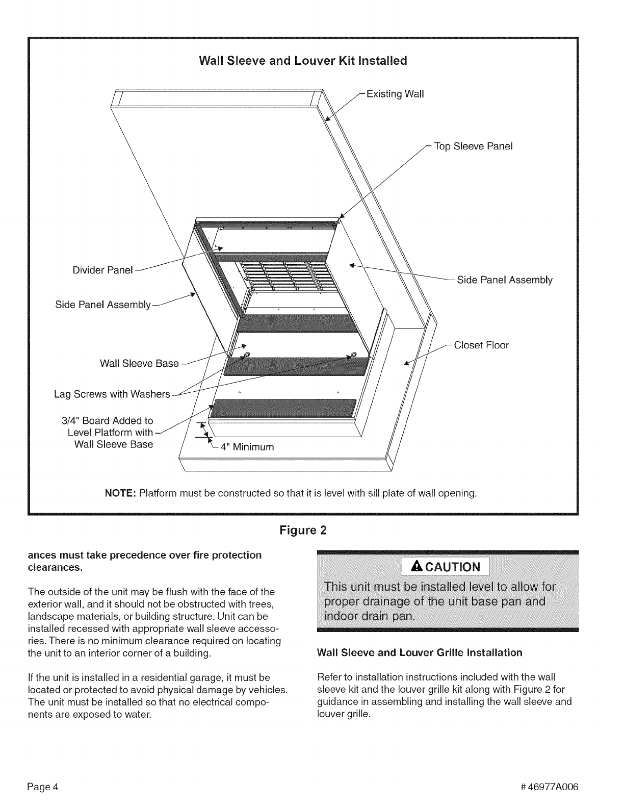
Wall Sleeve and Louver Kit installed
Sleeve Panel
Divider Panel
Side Panel Assembly
Side Panel Assembly
Wall Sleeve
Floor
Lag Screws with
3/4" Board Added to
Level Platform with
Wall Sleeve Base ;" Minimum
NOTE: Platform must be constructed so that it is level with sill plate of wall opening.
Figure 2
ances must take precedence over fire protection
clearances.
The outside of the unit may be flush with the face of the
exterior wall, and it should not be obstructed with trees,
landscape materials, or building structure. Unit can be
installed recessed with appropriate wall sleeve accesso-
ries. There is no minimum clearance required on locating
the unit to an interior corner of a building. Wail Sleeve and Louver Grille Installation
If the unit is installed in a residential garage, it must be
located or protected to avoid physical damage by vehicles.
The unit must be installed so that no electrical compo-
nents are exposed to water.
Refer to installation instructions included with the wall
sleeve kit and the louver grille kit along with Figure 2 for
guidance in assembling and installing the wall sleeve and
louver grille.
Page 4 #46977A006
Venting
The venting system is an integral part of the appliance,
The venting system must not be modified in any matter
other than what is specified in these instructions.
This appliance should be installed in a location such that
the vent outlet is located in the following manner:
1. Distances to windows that open, building openings, or
public walkways should be consistent with the National
Fuel Gas Code Z223.1 or CAN/CGA-B149.1 & .2.
,For U.S. installations, the vent system shall terminate
a minimum horizontal clearance of 4' from electric
meters, regulators, and relief equipment. For installa-
tions in Canada, refer to the current CAN/CGA-B149.1
& .2 or with the authorities having local jurisdiction.
3. Flue products will not cause degradation to building
materials.
The unit contains an exhaust blower. The blower draws the
combustion products out of the heat exchanger together
with dilution air and forces the mixture from the unit to the
outside. No special provisions are required for supplying
air for combustion, nor is a chimney required.
The vent outlet must be extended (see Vent Pipe Instal-
lation on page 6).
The venting system is designed for proper operation under
all weather conditions and for winds up to 40 miles per hour.
Existing Venting Systems
When an existing furnace is removed or replaced, the
original venting system may no longer be sized to properly
vent the attached appliances. An improperly sized venting
system can result in spillage of flue products into the living
space, the formation of condensate, leakage, etc. Refer to
the WARNING box in the next column for proper test
procedure.
[, WARNING
CARBON MONOXIDE POiSONiNG HAZARD
Failure to follow the steps outlined below for each
appliance connected to the venting system being
placed into operation could result in carbon monox-
ide poisoning or death.
The following steps shall be followed for each appli-
ance connected to the venting system being placed
into operation, while all other appliances connected to
the common venting system are not in operation:
1. Seal any unused openings in the common venting
system.
,Visually inspect the venting system for proper size
and horizontal pitch, as required in the National
Fuel Gas Code, ANSI Z223.1/NFPA 54 (latest
edition) or the CSA B149.1, Natural Gas and
Propane Installation Codes and these instructions.
Determine that there is no blockage or restriction,
leakage, corrosion, or other deficiencies which
could cause an unsafe condition.
,As far as practical, close all building doors and
windows between the space in which the
appliance(s) connected to the venting system are
located and other spaces in the building.
4. Close fireplace dampers.
,Turn on clothes dryers and any appliance not
connected to the venting system. Turn on any
exhaust fans, such as range hoods and bath-
room exhausts, so they are operating at maxi-
mum speed. Do not operate a summer exhaust
fan.
6. Follow the lighting instructions. Place the unit
being inspected in operation. Adjust the thermo-
stat so appliance is operating continuously.
,Test for spillage from draft hood equipped appli-
ances at the draft hood relief opening after
5 minutes of main burner operation. Use the flame
of a match or candle.
,If improper venting is observed during any of the
above tests, the venting system must be corrected
in accordance with the National Fuel Gas Code,
ANSI Z223.1/NFPA 54 (latest edition) and/or the
CSA B149.1, Natural Gas and Propane Installa-
tion Codes.
,After it has been determined that each appliance
remaining connected to the venting system
properly vents when tested as outlined above,
return doors, windows, exhaust fans, fireplace
dampers, and any other gas-fired burning appli-
ance to their previous conditions of use.
#46977A006 Page5
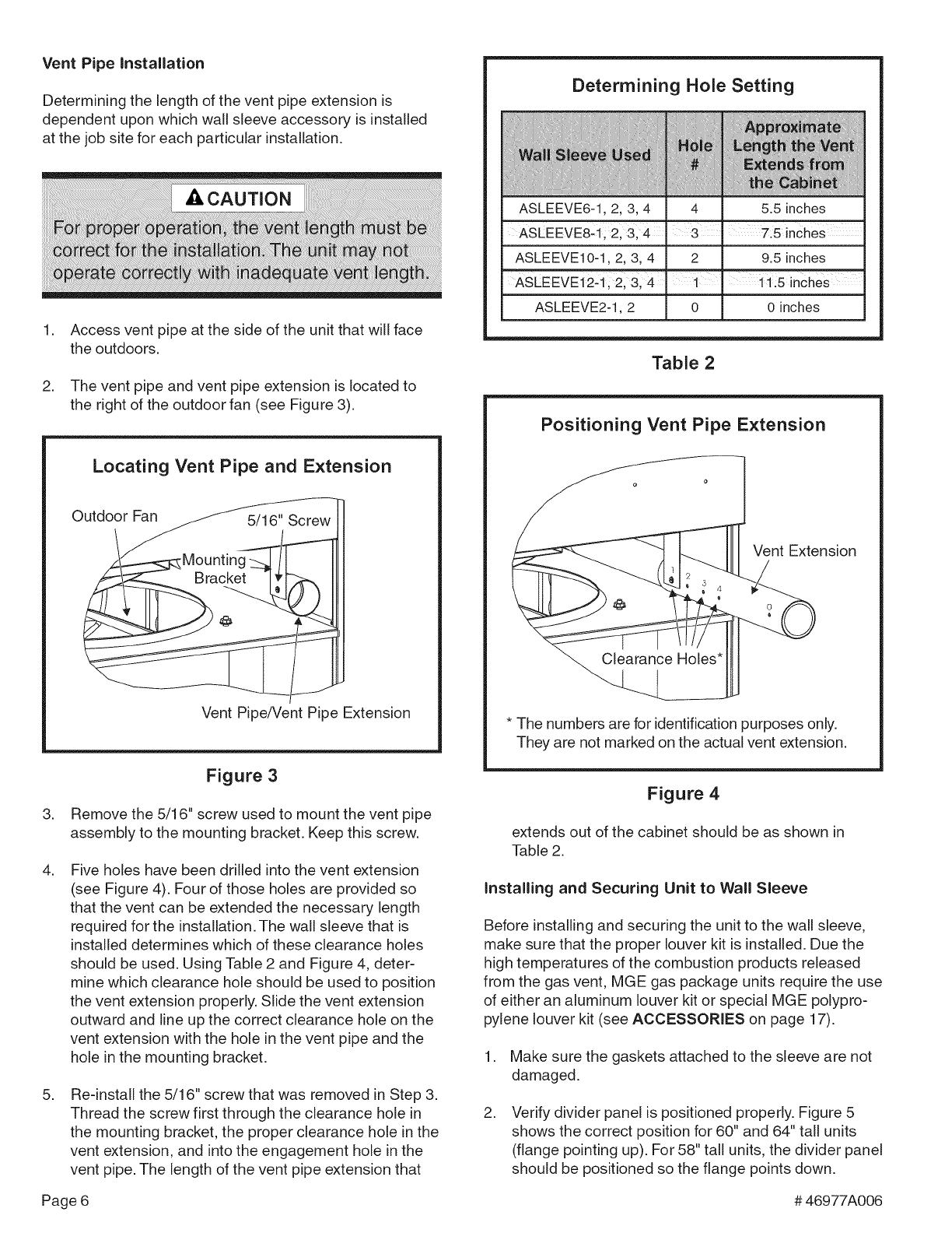
Vent Pipe Installation
Determining the length of the vent pipe extension is
dependent upon which wall sleeve accessory is installed
at the job site for each particular installation.
,
,
Access vent pipe at the side of the unit that will face
the outdoors.
The vent pipe and vent pipe extension is located to
the right of the outdoor fan (see Figure 3).
Locating Vent Pipe and Extension
Outdoor Fan
Vent Pipe/Vent Pipe Extension
Figure 3
3. Remove the 5/16" screw used to mount the vent pipe
assembly to the mounting bracket. Keep this screw.
,Five holes have been drilled into the vent extension
(see Figure 4). Four of those holes are provided so
that the vent can be extended the necessary length
required for the installation. The wall sleeve that is
installed determines which of these clearance holes
should be used. Using Table 2 and Figure 4, deter-
mine which clearance hole should be used to position
the vent extension properly. Slide the vent extension
outward and line up the correct clearance hole on the
vent extension with the hole in the vent pipe and the
hole in the mounting bracket.
,Re-install the 5/16" screw that was removed in Step 3.
Thread the screw first through the clearance hole in
the mounting bracket, the proper clearance hole in the
vent extension, and into the engagement hole in the
vent pipe. The length of the vent pipe extension that
Determining Hole Setting
ASLEEVE6-1, 2, 3, 4 ! 4 5.5 inches
ASLEEVE8-1, 2' 3, 4 7:5 inches
ASLEEVE10-1,2, 3,4j 2 9.5 nches
i 4 !php
ASLEEVE2-1,2 I 0 0 inches
Table 2
Positioning Vent Pipe Extension
Vent Extension
J
* The numbers are for identification purposes only.
They are not marked on the actual vent extension.
Figure 4
extends out of the cabinet should be as shown in
Table 2.
Installing and Securing Unit to Wall Sleeve
Before installing and securing the unit to the wall sleeve,
make sure that the proper louver kit is installed. Due the
high temperatures of the combustion products released
from the gas vent, MGE gas package units require the use
of either an aluminum louver kit or special MGE polypro-
pylene louver kit (see ACCESSORIES on page 17).
1. Make sure the gaskets attached to the sleeve are not
damaged.
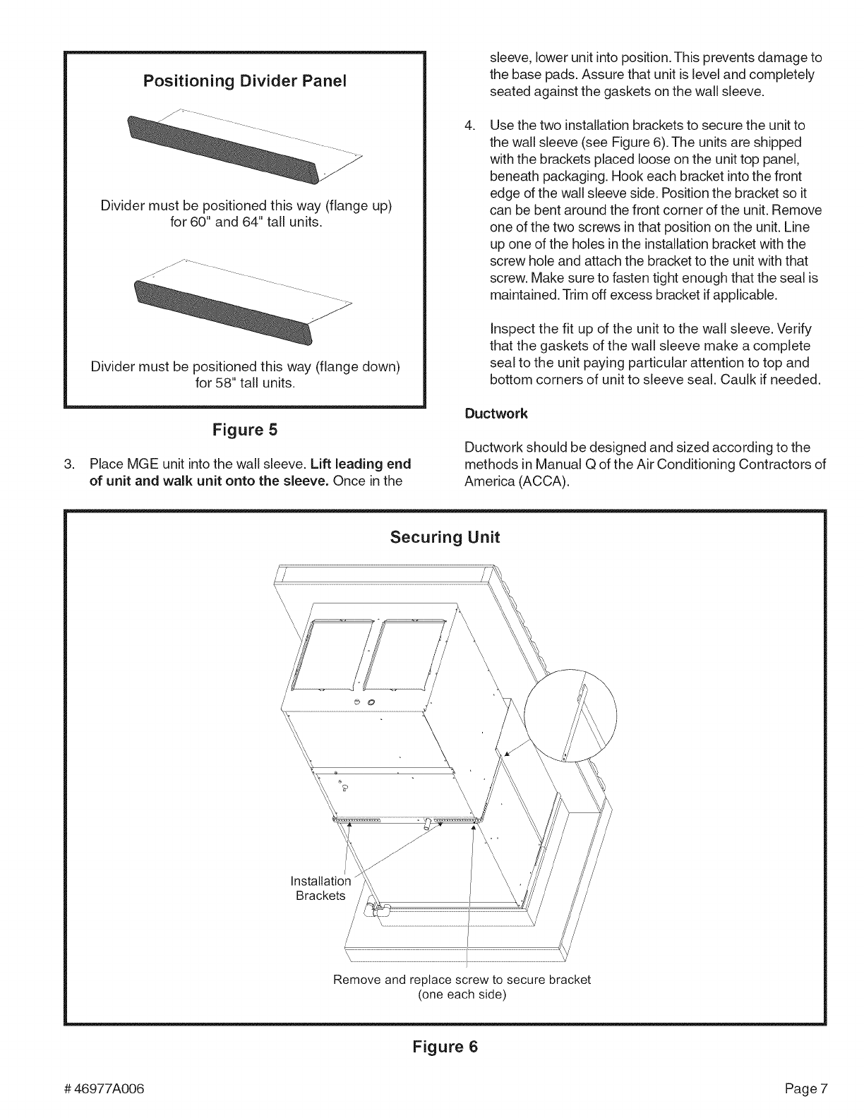
,Verify divider panel is positioned properly. Figure 5
shows the correct position for 60" and 64" tall units
(flange pointing up). For 58" tall units, the divider panel
should be positioned so the flange points down.
Page 6 #46977A006
Positioning Divider Panel
Divider must be positioned this way (flange up)
for 60" and 64" tall units.
Divider must be positioned this way (flange down)
for 58" tall units.
,
Figure 5
Place MGE unit into the wall sleeve. Lift leading end
of unit and walk unit onto the sleeve. Once in the
sleeve, lower unit into position. This prevents damage to
the base pads. Assure that unit is level and completely
seated against the gaskets on the wall sleeve.
.Use the two installation brackets to secure the unit to
the wall sleeve (see Figure 6). The units are shipped
with the brackets placed loose on the unit top panel,
beneath packaging. Hook each bracket into the front
edge of the wall sleeve side. Position the bracket so it
can be bent around the front corner of the unit. Remove
one of the two screws in that position on the unit. Line
up one of the holes in the installation bracket with the
screw hole and attach the bracket to the unit with that
screw. Make sure to fasten tight enough that the seal is
maintained. Trim off excess bracket if applicable.
Inspect the fit up of the unit to the wall sleeve. Verify
that the gaskets of the wall sleeve make a complete
seal to the unit paying particular attention to top and
bottom corners of unit to sleeve seal. Caulk if needed.
Ductwork
Ductwork should be designed and sized according to the
methods in Manual Q of the Air Conditioning Contractors of
America (ACCA).
Securing Unit
\\
\\\\\\\
Brackets
Remove and replace screw to secure bracket
(one each side)
Figure 6
#46977A006 Page 7
Checkunitairsupplyoutletfor debrisbeforemaking
ductworkconnections.
Itisrecommendedthatsupplyandreturnductconnections
attheunitbemadewithflexiblejoints.Ifflexibleductsare
used,a6"sheetmetalstartercollarisrequired.
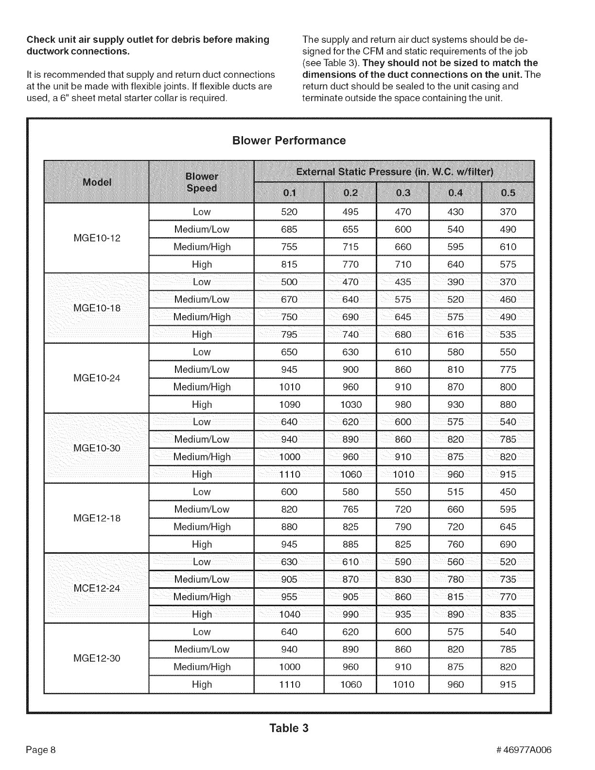
Thesupplyandreturnairductsystemsshouldbede-
signedfortheCFMandstaticrequirementsofthejob
(seeTable3).Theyshouldnotbesizedto matchthe
dimensionsof the duct connections on the unit. The
return duct should be sealed to the unit casing and
terminate outside the space containing the unit.
Blower Performance
1i ::
Low
Medium/Low
MGE10-12 Medium/High
High
MGE10-24
MGE12-18
Low
Medium/Low
Medium/High
High
52O
685
755
815
65O
945
1010
1090
495
655
715
77O
630
900
960
1030
Medium/Low 940. 890
470 430
600 540
660 595
710 640
645
610 580
860 810
910 870
980 930
s6o
I m
Medium/High 1000 960 1910 875
010
Low
Medium/Low
Medium/High
High
600
820
88O
945
58O
765
825
885
55O
72O
79O
825
37O
49O
610
575
460
490
55O
775
8OO
88O
960 _ 915
515 450
660 595
720 645
760 690
830 780
MCE12_24 ....
Medium/High 955 905 860 815 770
Low 640 620 600 575 540
Medium/Low 940 890 860 820 785
MGE12-30 Medium/High 1000 960 910 875 820
High 1110 1060 1010 960 915
Table 3
Page 8 #46977A006
Do not screw into the side of the drain pan, or into the
indoor coil.
Air Filter
All indoor return air must be filtered. A washable filter is
furnished with the unit, located in the return air opening. If
return duct is installed, provisions must be made to
accommodate filter servicing.
The filter should be cleaned at least three times during
each of the heating and cooling seasons, or more fre-
quently if unusual conditions are encountered. To clean
the washable filter, shake filter to remove excess dirt
and/or use a vacuum cleaner. Wash filter in soap or
detergent water and replace after filter is dry. It is not
necessary to oil the filter after washing.
If an installation is made in which it is more desirable to
mount the filter exterior to the unit, in the return duct work
or elsewhere, the washable filter can be used or replaced
with a disposable filter. If a disposable filter is used, use
the information provided in Table 4 when sizing the
disposable filter.
Minimum Required Surface Area
for Disposable Filters
MGE*12 192 square inches
MGE*18 288 square inches
MGE*24 384 square inches
. I
MGE 30 480 Square inches
10 and 12 SEER models
Table 4
Condensate Drain
Provisions must be made to properly drain the indoor and
outdoor drain pans of this appliance.
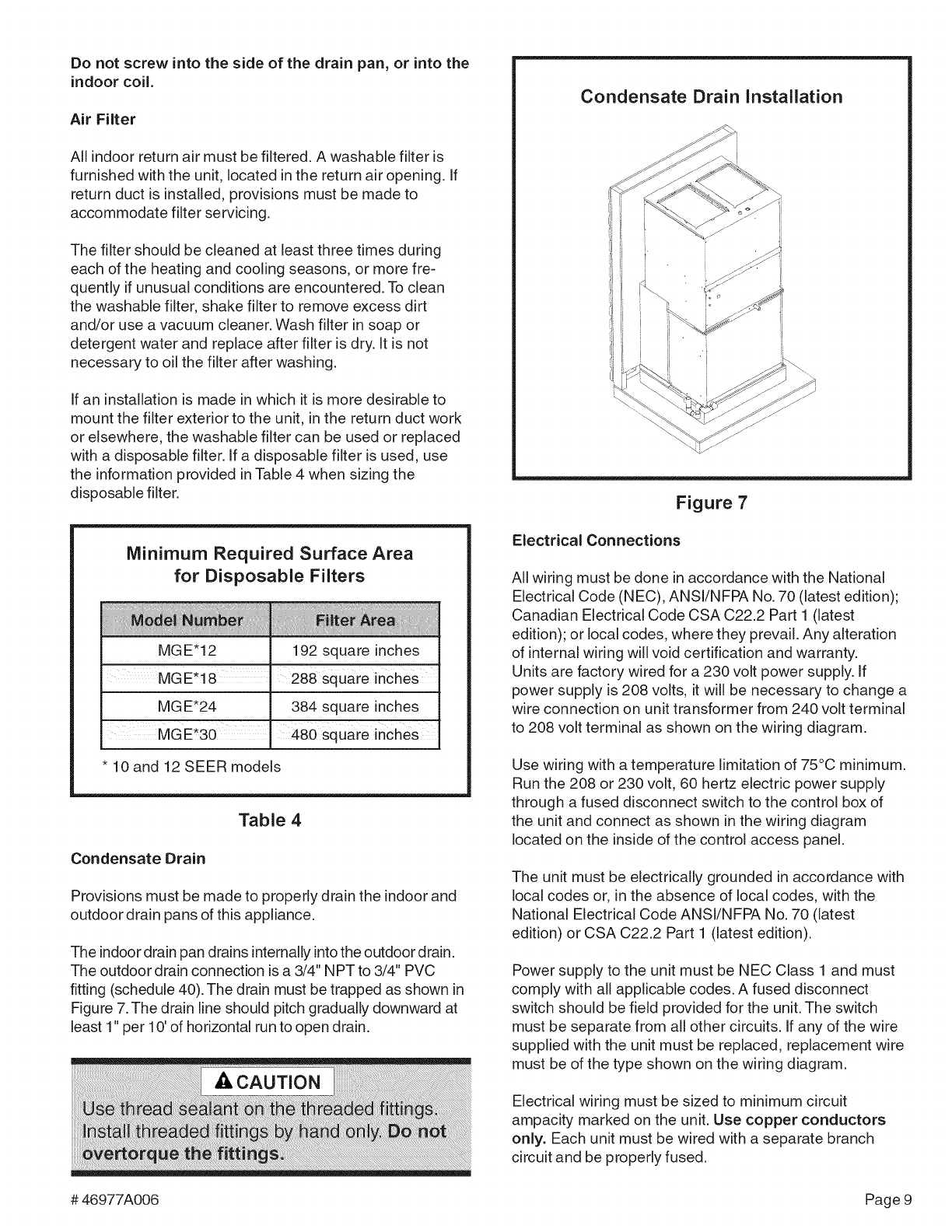
The indoor drain pan drains internally into the outdoor drain.
The outdoor drain connection is a 3/4" NPT to 3/4" PVC
fitting (schedule 40). The drain must be trapped as shown in
Figure 7. The drain line should pitch gradually downward at
least 1" per 10' of horizontal run to open drain.
Condensate Drain Installation
Figure 7
Electrical Connections
All wiring must be done in accordance with the National
Electrical Code (NEC), ANSI/NFPA No. 70 (latest edition);
Canadian Electrical Code CSA C22.2 Part 1 (latest
edition); or local codes, where they prevail. Any alteration
of internal wiring will void certification and warranty.
Units are factory wired for a 230 volt power supply. If
power supply is 208 volts, it will be necessary to change a
wire connection on unit transformer from 240 volt terminal
to 208 volt terminal as shown on the wiring diagram.
Use wiring with a temperature limitation of 75°C minimum.
Run the 208 or 230 volt, 60 hertz electric power supply
through a fused disconnect switch to the control box of
the unit and connect as shown in the wiring diagram
located on the inside of the control access panel.
The unit must be electrically grounded in accordance with
local codes or, in the absence of local codes, with the
National Electrical Code ANSI/NFPA No. 70 (latest
edition) or CSA C22.2 Part 1 (latest edition).
Power supply to the unit must be NEC Class 1 and must
comply with all applicable codes. A fused disconnect
switch should be field provided for the unit. The switch
must be separate from all other circuits. If any of the wire
supplied with the unit must be replaced, replacement wire
must be of the type shown on the wiring diagram.
Electrical wiring must be sized to minimum circuit
ampacity marked on the unit. Use copper conductors
only. Each unit must be wired with a separate branch
circuit and be properly fused.
#46977A006 Page9
Gas Supply and Piping
Refer to unit rating plate to make sure the furnace is
equipped to burn the gas supplied (natural or propane).
Gas supply piping should be installed in accordance with
local codes and the regulations of the utility. Piping must
be of adequate size to prevent undue pressure drop.
Consult the local utility or gas supplier for complete details
on special requirements for sizing gas piping.
If local codes allow the use of a flexible gas appliance
connector, always use a new listed connector. Do not use
a connector which has previously serviced another gas
appliance.
Pipe connections must be tight, and a non-hardening pipe
compound resistant to liquefied petroleum gases should be
used.
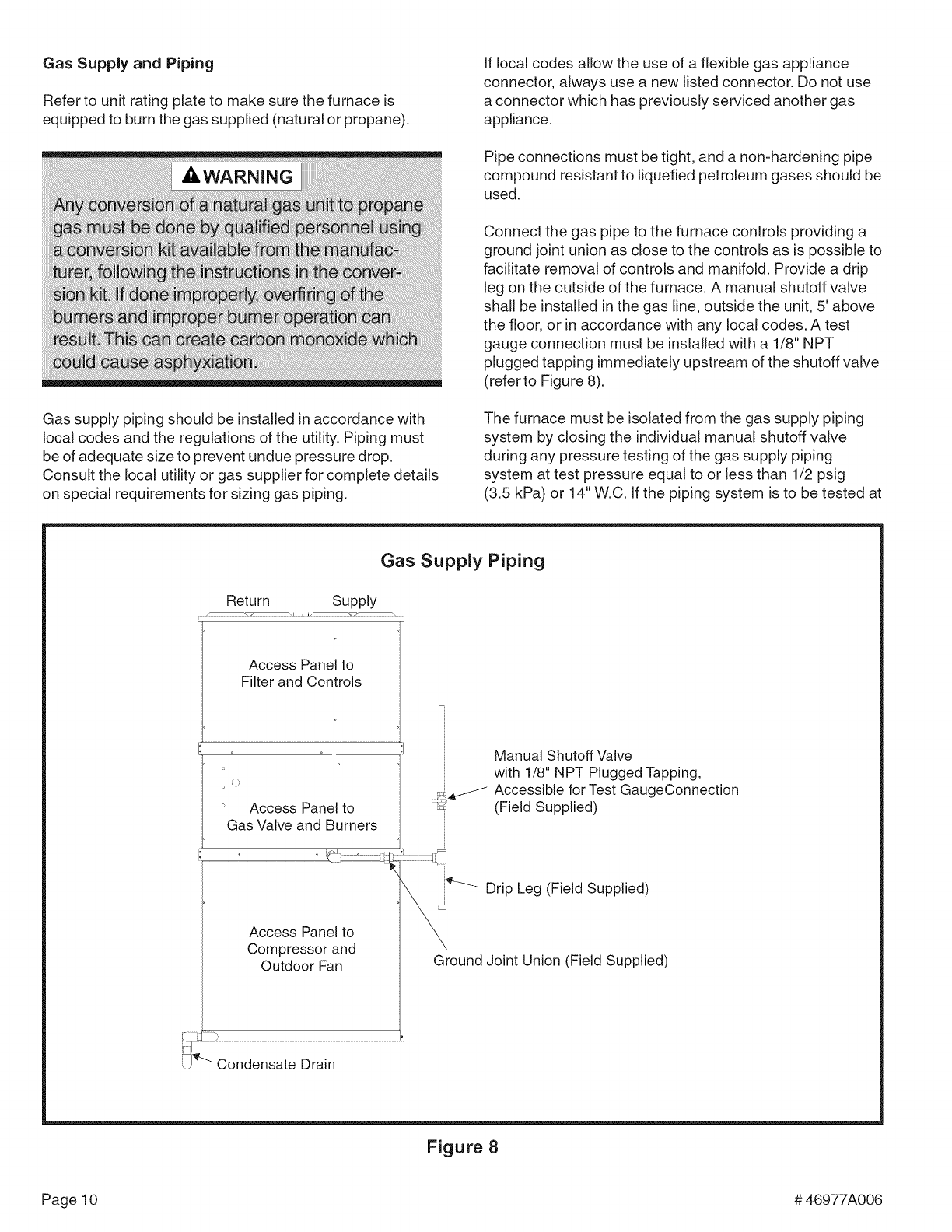
Connect the gas pipe to the furnace controls providing a
ground joint union as close to the controls as is possible to
facilitate removal of controls and manifold. Provide a drip
leg on the outside of the furnace. A manual shutoff valve
shall be installed in the gas line, outside the unit, 5' above
the floor, or in accordance with any local codes. A test
gauge connection must be installed with a 1/8" NPT
plugged tapping immediately upstream of the shutoff valve
(refer to Figure 8).
The furnace must be isolated from the gas supply piping
system by closing the individual manual shutoff valve
during any pressure testing of the gas supply piping
system at test pressure equal to or less than 1/2 psig
(3.5 kPa) or 14" W.C. If the piping system is to be tested at
Gas Supply Piping
Return Supply
Access Panel to
Filter and Controls
_ Access Panel to
Gas Valve and Burners
Manual Shutoff Valve
with 1/8" NPT Plugged Tapping,
Accessible for Test GaugeConnection
(Field Supplied)
Access Panel to
Compressor and
Outdoor Fan
Drip Leg (Field Supplied)
Ground Joint Union (Field Supplied)
Figure 8
Page10 #46977A006
pressuresinexcessof1/2psig(3.5kPa),thefurnaceand
itsappliancemaingasvalvemustbedisconnectedfrom
thegassupplypipingsystem.
Aftergaspipingiscomplete,carefullycheckallpiping
connections(factoryandfield)forgasleaks.Usea leak
detectingsolutionorotherpreferredmeans.Somesoaps
usedforleakdetectionarecorrosivetocertainmetals.
Carefullyrinsepipingthoroughlyafterleakdetectionhas
beencompleted.
Thermostat
The room thermostat should be located on an inside wall
where it will not be subject to drafts, sun exposure, or heat
from electrical fixtures or appliances. Follow manufacturer's
instructions enclosed with the thermostat for general
installation procedures. Color-coded insulated wires (#18
AWG) should be used to connect the thermostat to the unit.
#46977A006 Page11
START=U P
For Your Safety Read Before Lighting
To Shut Down Unit:
1. Turn off electrical power to unit.
2. Depress and turn the gas valve knob to the "OFF"
position (see Figure 9).
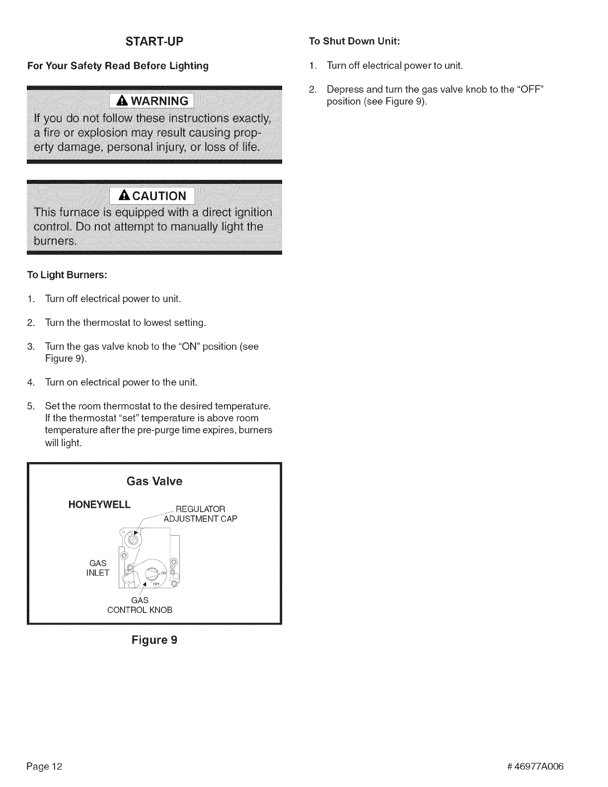
To Light Burners:
1. Turn off electrical power to unit.
2. Turn the thermostat to lowest setting.
3. Turn the gas valve knob to the "ON" position (see
Figure 9).
4. Turn on electrical power to the unit.
5. Set the room thermostat to the desired temperature.
If the thermostat "set" temperature is above room
temperature after the pre-purge time expires, burners
will light.
Gas Valve
HONEYWELL
GAS
INLET
/J
GAS
CONTROL KNOB
Figure 9
Page12 #46977A006
OPERATION
Operation of the unit is automatic and will provide heating
and cooling depending on the setting of the thermostat.
Heating
1. Turn on main power supply.
2. Open manual gas shutoff valve.
3. Set thermostat system to "HEAT".
4. Set thermostat to temperature desired.
Sequence of Operation
1. Thermostat calls for heat.
2. Combustion blower starts and proper air flow is
proven by the pressure switch closing.
3. Blower continues to operate for 30 seconds prior to
the burners lighting.
4. Ignition control begins spark and opens gas valve. The
burners are lit. Ignition is proved through flame sensor.
5. Circulating air blower starts 30 seconds after the
burners light.
6. When the thermostat is satisfied, the burners and
combustion blower shut off.
7. Circulating air blower will shut off 120 seconds later.
Ifthe burners should fail to ignite, the ignition control will try
to ignite the burners a total of three times. Should the
burners fail to ignite within the three trials for ignition, the
ignition control will lock out for 1 hour before beginning
another ignition cycle. To reset the control, turn the thermo-
stat down or off for 10 seconds and then set to desired
setting. At this time, the ignition sequence will try again.
Cooling
1. Set thermostat system switch to "COOL".
2. Set thermostat to temperature desired.
NOTE: When Y is energized, the combustion blower will
operate for 10 seconds. The purpose of this action is to
deter insect nesting in the flue pipe.
To Shut Down Unit
For temporary or short periods of shutdown, set the
thermostat system switch to "OFF". For a prolonged
period of shutdown, set the thermostat system switch to
"OFF" and turn off the electrical power supply and the gas
supply to the unit.
Adjustments -Heating Section
Temperature Rise
At time of installation, the temperature rise must be adjusted
to be within the range specified on the unit rating plate.
Checking and Adjusting Gas input
The gas input must not exceed the figures shown on the
rating plate. The unit is equipped for rated inputs with
manifold pressures of: 3.5" W.C. for natural gas and 10.0"
W.C. for propane. The furnace requires conversion for use
with propane (a propane conversion kit is available from
the manufacturer).
The manifold pressure can be measured by removing the
pipe plug in the downstream side of the gas valve and
connecting a water manometer or gauge.
Only small variations in gas input may be made by
adjusting the regulator. In no case should the final
manifold pressure vary more than 0.3" W.C. for
natural gas or 0.7" W.C. for propane.
To adjust the regulator, turn the adjusting screw on the
regulator clockwise to increase pressure and input or
counterclockwise to decrease pressure and input.
For Natural Gas: Check the furnace rate by observing the
gas meter, when available, making sure all other gas
appliances are turned off. The test hand on the meter
should be timed for at least one revolution. Note the
number of seconds for one revolution.
BTU/HR =Cubic Feet Per Revolution × 3600 × Heating
iNPUT #Seconds Per Revolution Value
The heating value of the gas can be obtained from the
local utility company.
For Propane Gas: The only check for the furnace rate is
to properly adjust the manifold pressure using a manom-
eter and the information found in Table 5 on page 14.
Typical manifold set point for installations at altitudes from
0 to 4500' above sea level is 10.0" W.C.
Adjustments -Cooling Section
No adjustments are required or should be attempted
regarding any of the components of the cooling system.
#46977A006 Page13
2000
3000
4OOO
i :4500
5000
5500
6000
6500
7000
75oo
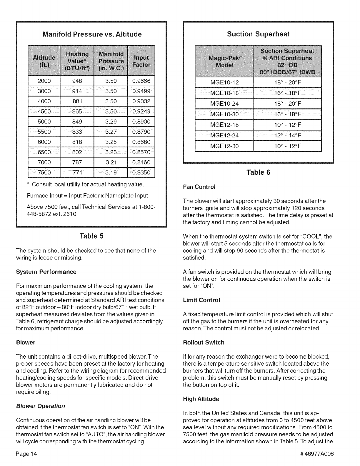
Manifold Pressure vs. Altitude
m
M:ea_in
value
U/f1
948
914
881
865
849
_anJt_Id
3.50
3.50
3:50
3.29
0.9666
o:9499
0.9332
i0:9249
0.8900
833 3:27 0.8790
3.25 0.8680
m
3:23 0.8570
3.21 0.8460
3!19 0.8350
818
802
787
771
* Consult local utility for actual heating value.
Furnace Input = Input Factor x Nameplate Input
Above 7500 feet, call Technical Services at 1-800-
448-5872 ext. 2610.
Table 5
The system should be checked to see that none of the
wiring is loose or missing.
System Performance
For maximum performance of the cooling system, the
operating temperatures and pressures should be checked
and superheat determined at Standard ARI test conditions
of 82°F outdoor- 80°F indoor dry bulb/67°F wet bulb. If
superheat measured deviates from the values given in
Table 6, refrigerant charge should be adjusted accordingly
for maximum performance.
Blower
The unit contains a direct-drive, multispeed blower. The
proper speeds have been preset at the factory for heating
and cooling. Refer to the wiring diagram for recommended
heating/cooling speeds for specific models. Direct-drive
blower motors are permanently lubricated and do not
require oiling.
Blower Operation
Continuous operation of the air handling blower will be
obtained if the thermostat fan switch is set to "ON". With the
thermostat fan switch set to "AUTO", the air handling blower
will cycle corresponding with the thermostat cycling.
Suction Superheat
MGE10-12 18° - 20°F
MGE10_18
MGE10-24 18° - 20°F
MGE10;30 16_ _180F
MGE12-18 10° - 12°F
i
MGE12_24 12° # 14°F
MGE12-30 10° - 12°F
Table 6
Fan Control
The blower will start approximately 30 seconds after the
burners ignite and will stop approximately 120 seconds
after the thermostat is satisfied. The time delay is preset at
the factory and timing cannot be adjusted.
When the thermostat system switch is set for "COOL", the
blower will start 5 seconds after the thermostat calls for
cooling and will stop 90 seconds after the thermostat is
satisfied.
A fan switch is provided on the thermostat which will bring
the blower on for continuous operation when the switch is
set for "ON".
Limit Control
A fixed temperature limit control is provided which will shut
off the gas to the burners if the unit is overheated for any
reason. The control must not be adjusted or relocated.
Rollout Switch
If for any reason the exchanger were to become blocked,
there is a temperature sensitive switch located above the
burners that will turn off the burners. After correcting the
problem, this switch must be manually reset by pressing
the button on top of it.
High Altitude
In both the United States and Canada, this unit is ap-
proved for operation at altitudes from 0 to 4500 feet above
sea level without any required modifications. From 4500 to
7500 feet, the gas manifold pressure needs to be adjusted
according to the information shown inTable 5. To adjust the
Page14 #46977A006
manifoldpressure,refertoprevioussectionChecking and
Adjusting Gas Input on page 13. For installations above
7500 feet, call Technical Service at 1-800-448-5872 ext.
2610 for assistance.
Installation and Operation in Extremely Cold
Weather Areas
In areas where extremely cold outdoor temperatures
(below - 20°F) can be expected, some additional installa-
tion and operating precautions should be taken. The
following precautions are designed to prevent possible
vent system ice blockage that could result in safety
shutdown of the burners:
,Adjust to the highest achievable temperature rise
within the rise and static pressure ranges specified on
the rating plate. Depending on specific model, it may
be possible to change to a lower heating blower speed
tap to get a higher temperature rise. This also in-
creases comfort.
2. Make sure there are no leaks of outside air into the
return air system.
3. Keep the outside louver grille as free as possible of
any ice that may form and obstruct the flue outlet.
#46977A006 Page15
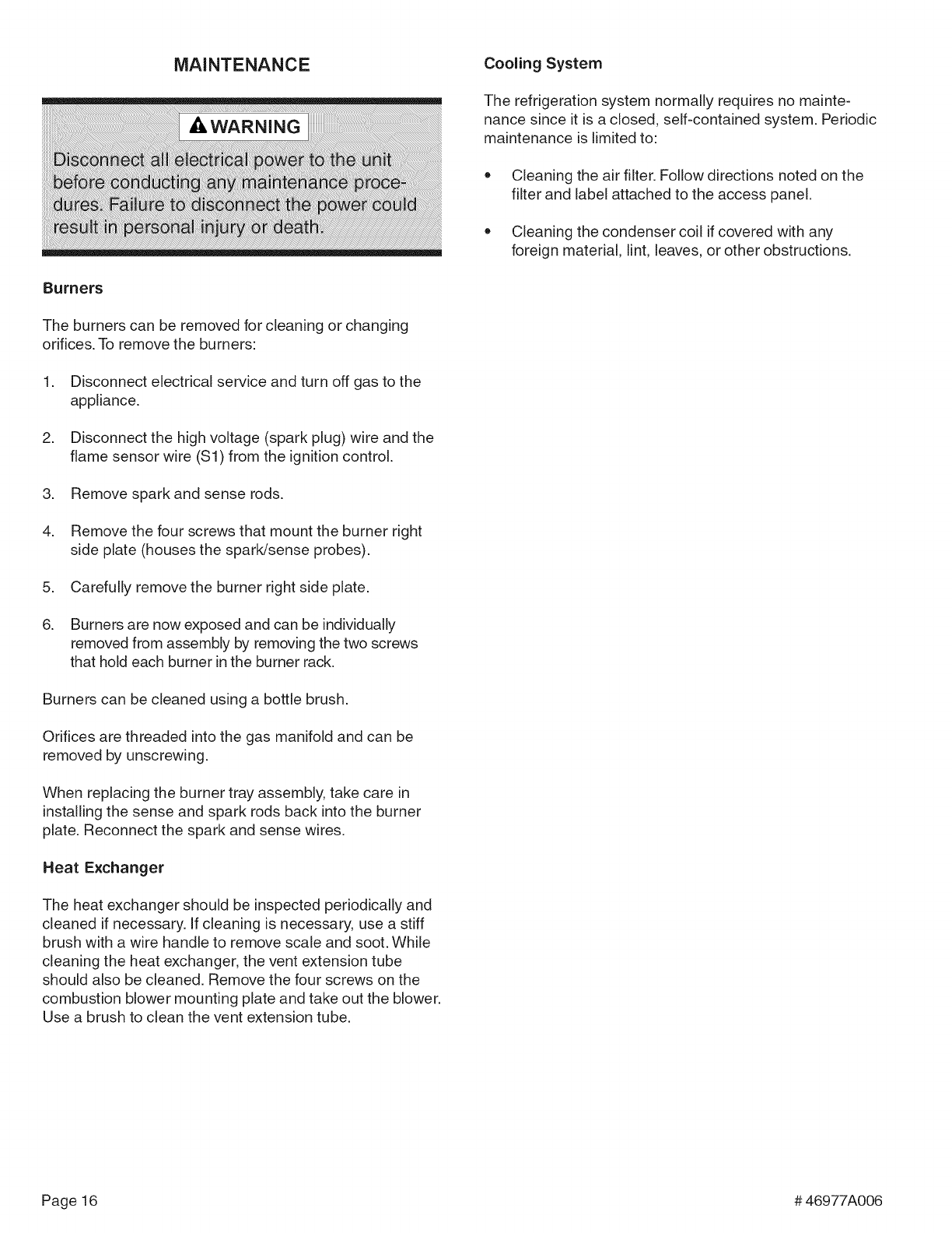
MAINTENANCE Cooling System
Burners
The burners can be removed for cleaning or changing
orifices. To remove the burners:
1. Disconnect electrical service and turn off gas to the
appliance.
2. Disconnect the high voltage (spark plug) wire and the
flame sensor wire (Sl) from the ignition control.
3. Remove spark and sense rods.
4. Remove the four screws that mount the burner right
side plate (houses the spark/sense probes).
5. Carefully remove the burner right side plate.
6. Burners are now exposed and can be individually
removed from assembly by removing the two screws
that hold each burner in the burner rack.
Burners can be cleaned using a bottle brush.
Orifices are threaded into the gas manifold and can be
removed by unscrewing.
When replacing the burner tray assembly, take care in
installing the sense and spark rods back into the burner
plate. Reconnect the spark and sense wires.
Heat Exchanger
The heat exchanger should be inspected periodically and
cleaned if necessary. If cleaning is necessary, use a stiff
brush with a wire handle to remove scale and soot. While
cleaning the heat exchanger, the vent extension tube
should also be cleaned. Remove the four screws on the
combustion blower mounting plate and take out the blower.
Use a brush to clean the vent extension tube.
The refrigeration system normally requires no mainte-
nance since it is a closed, self-contained system. Periodic
maintenance is limited to:
Cleaning the air filter. Follow directions noted on the
filter and label attached to the access panel.
Cleaning the condenser coil if covered with any
foreign material, lint, leaves, or other obstructions.
Page16 #46977A006
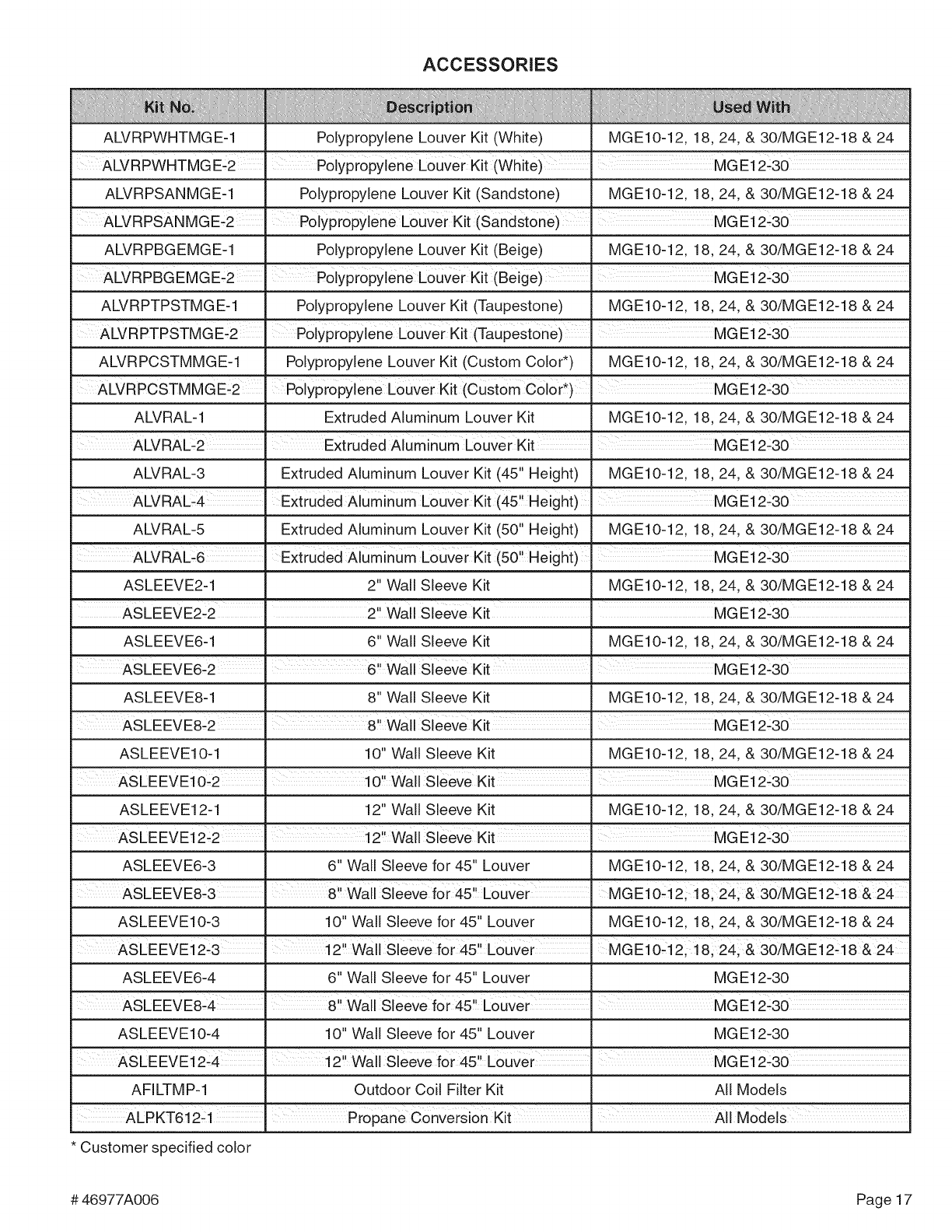
ACCESSORIES
AWRPWHTMGE-1
ALvRPWHTMG E-2
ALVRPSANMGE-1
ALVRPSANMGE-2
ALVRPBGEMGE-1
ALVRPBGEMGE'2
ALVRPTPSTMGE-1
ALVRPTPSTMGE-2
ALVRPCSTMMGE-1
ALVRPCSTMMGE-2
ALVRAL-1
ALVRAL-2
ALVRAL-3
ALVRAL_4
ALVRAL-5
Polypropylene Louver Kit (White) MGE10-12, 18, 24, & 30/MGE12-18 & 24
Polypr0pylene Louver Kit(White)MG E12-30
Polypropylene Louver Kit (Sandstone) MGE10-12, 18, 24, & 30/MGE12-18 & 24
Polypropylene Louver Kit (Sandstone)
Polypropylene Louver Kit (Beige) MGE10-12, 18, 24, & 30/MGE12-18 & 24
P01ypr0pylene Louver Kit (Beige)MG E12-30
Polypropylene Louver Kit (Taupestone) MGE10-12, 18, 24, & 30/MGE12-18 & 24
Polypr0pylene L0uver Kit (Taupest0ne)Me E12-30
Polypropylene Louver Kit (Custom Color*) MGE10-12, 18, 24, & 30/MGE12-18 & 24
Polypropylene LOuVer Kit (custom Col0r _)
Extruded Aluminum Louver Kit MGE10-12, 18, 24, & 30/MGE12-18 & 24
ExtrUded Aluminum Louver Kit' MG E12:30
Extruded Aluminum Louver Kit (45" Height) MGE10-12, 18, 24, & 30/MGE12-18 & 24
Extruded Aluminum Louver Kit (45,!Height)' MGE12:30
Extruded Aluminum Louver Kit (50" Height) MGE10-12, 18, 24, & 30/MGE12-18 & 24
ALVRAL_6 'ExtrUded Aluminum Louver Kit (50 Height)
ASLEEVE2-1 2" Wall Sleeve Kit MGE10-12, 18, 24, & 30/MGE12-18 & 24
'Ii ' I
ASLEEVE2.2 2 Wa S eeve Kit MGE12.30
ASLEEVE6-1 6" Wall Sleeve Kit MGE10-12, 18, 24, & 30/MGE12-18 & 24
ASLEEVEG2 6.! Wall Sleeve Kit MGE12.30
ASLEEVE8-1
ASLEEVE8_2
ASLEEVE10-1
ASLEEVE12-1
ASLEEVE12_2
ASLEEVE6-3
ASLEEVE8_3
ASLEEVE10-3
ASLEEVE12-3
ASLEEVE6-4
ASLEEVE8_4
ASLEEVE10-4
8" Wall Sleeve Kit
10" Wall Sleeve Kit
12" Wall Sleeve Kit
MGE10-12, 18, 24, & 30/MGE12-18 & 24
MGE10-12, 18, 24, & 30/MGE12-18 & 24
MGE10-12, 18, 24, & 30/MGE12-18 & 24
6" Wall Sleeve for 45" Louver MGE10-12, 18, 24, & 30/MGE12-18 & 24
8.! Wall Sleeve for 45, Louver' MGE10-12;18; 241 & 30/MGE12-18&24
10" Wall Sleeve for 45" Louver MGE10-12, 18, 24, & 30/MGE12-18 & 24
2!! Wall Sleeve for 45, LouVer MG E10_12!18i 241 & 30/MG E12-18&24
6" Wall Sleeve for 45" Louver MGE12-30
i 8'! Wall Sleeve for 45,, Louver I MG E12-30
10" Wall Sleeve for 45" Louver MG E12-30
AS EEEVEi 2L4' 12" Wall Sieeve for 45.,LouVer MG E12L30
AFILTMP-1 Outdoor Coil Filter Kit All Models
ALP KT612:1 P ropan e ConVers ion Kit AIi Models
* Customer specified color
#46977A006 Page17
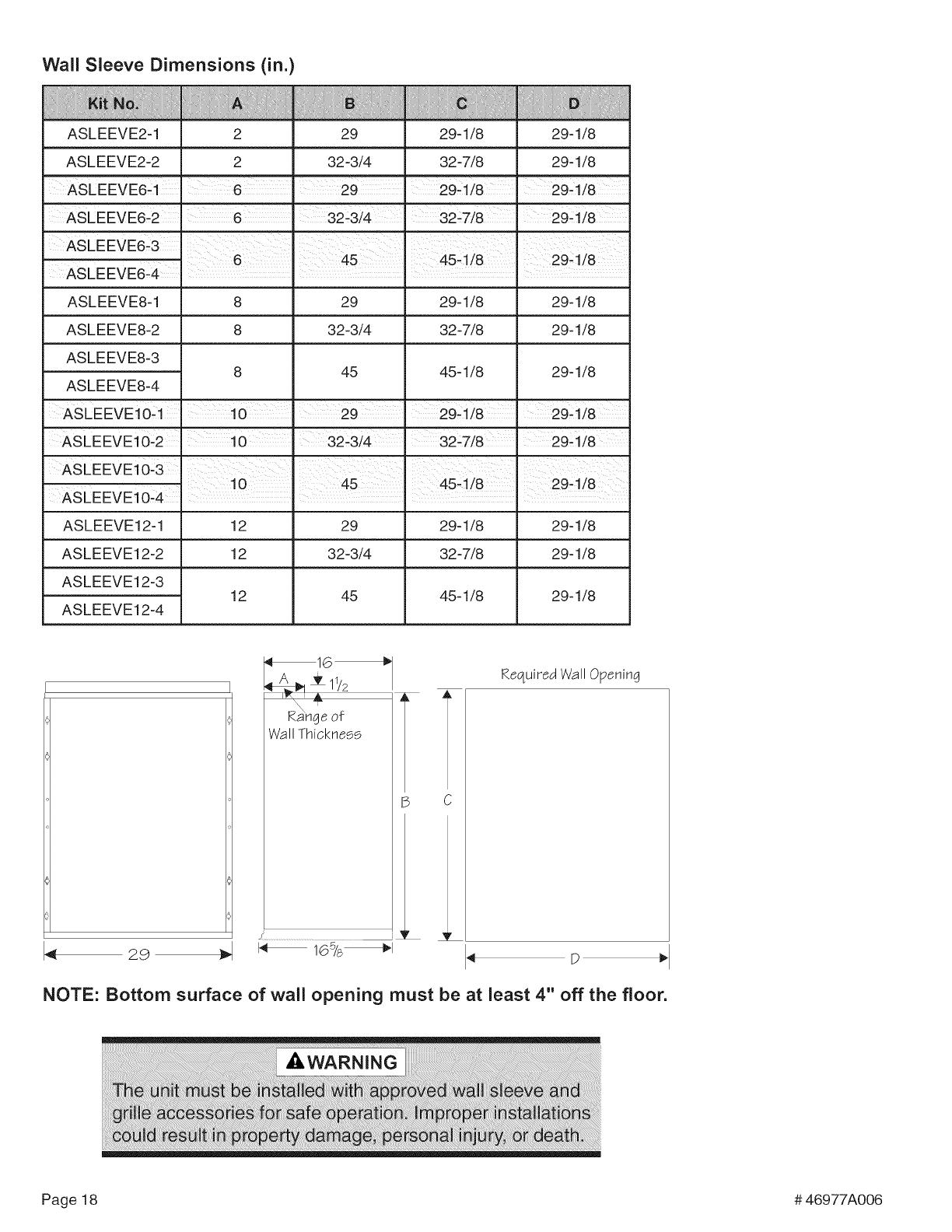
Wall Sleeve Dimensions (in.)
ASLEEVE2-1 2 29 29-1/8 29-1/8
AS LEEV E2-2 2 32 -3/4 32 -7/8 29-1/8
ASLEEVE6_2 I 32_3/4 I 32_7/8 I 29_i/8
ASLEEVE8-1 8 29 29-1/8 29-1/8
ASLEEVE8-2 8 32-3/4 32-7/8 29-1/8
ASLEEVE8-3
ASLEEVE8-4 45 45-1/8 29-1/8
ASLEEVEi 0--1 10 I 29 I 29--1/8 29--1/8
ASLEEVE10_2' 10 ' 32--W4. 32--7/8. 29-1/8
ASLEEVE10'3
ASLEEVE10-4 . I
ASLEEVE12-1 12 29 29-1/8 29-1/8
ASLEEVE12-2 12 32-3/4 32-7/8 29-1/8
ASLEEVE12-3 12 45 45-1/8 29-1/8
ASLEEVE12-4
_16_
waR_h_cek°_ss
165/s_1
B C
_V
Required Wall Opening
'q D _'
NOTE: Bottom surface of wall opening must be at least 4" off the floor.
Page 18 # 46977A006
q_
4_
(3)
-q
-q
>
o
o
o3
e=
C
_D
GO
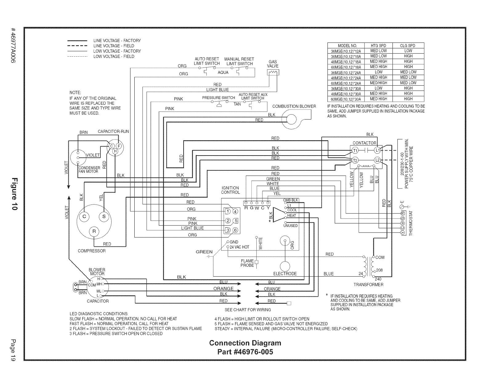
NOTE:
LINE VOLTAGE- FACTORY
LINE VOLTAGE- FIELD
LOW VOLTAGE- FACTORY
LOW VOLTAGE- FIELD AUTO RESET MANUAL RESET
LIMIT SWITCH LIMIT SWITCH GAS
ORG VALVE
ORG [_
RED
LIGHT BLUE
IF ANY OFTHE ORIGINAL
WIRE IS REPLACED THE
SAME SIZE AND TYPE WIRE
MUST BE USED.
BRN CAPACITOR-RUN
RED
COMPRESSOR
BLOWER
BRN
CAPACITOR
PINK
AUTO RESET AUX
PINK PRESSURE SWITCH LIMIT SWITCH
RED
RED
COMBUSTION BLOWER
BLK
BLK
BLK
RED
RED
BLK
IGNITION
CONTROL
RED
ORG
PINK
PINK
LIGHT BLUE
ORG
GREEN
_5
/ GNB ?----
24VAC HOT I_
FLAME ¢?
PROBE s
RED :
LED DIAGNOSTIC CONDITIONS:
SLOW FLASH = NORMAL OPERATION, NO CALL FOR HEAT
FAST FLASH = NORMAL OPERATION, CALL FOR HEAT
2 FLASH = SYSTEM LOCKOUT - FAILED TO DETECT OR SUSTAIN FLAME
3 FLASH = PRESSURE SWITCH OPEN OR CLOSED
BLK
BLK
RED
RED
RED
GREEN
WHITE
I I I BLUE
I I CMB BLK
RGWCY
UNUSED
ELECTRODE
_ BLU
ORANG E ORANGE
BLK BLK
4-
4- RED []
SEE CHART FOR WIRING
4 FLASH = HIGH LIMIT OR ROLLOUT SWITCH OPEN
MODELNO. HTGSPD CLGSPD
36MGE(10,12)*12A MEDLOW LOW
36MGE(10,12)*18A NED LOW HIGH
48MGE(10,12)*18A NED HIGH HIGH
60MGE(10,12)*18A NED HIGH HIGH
36MGE(10,12)'24A LOW NED LOW
48MGE(10,12)*24A NED HIGH NED LOW
60MGE(10J2)*24A MED/HIGH MEDLOW
36MGE(1&12)*30A LOW HIGH
48MGE(1&12)*30A MEDHIGH HIGH
60MGE(10,12)*30A NED HIGH HIGH
IFINSTALLATIONREQUIRESHEATINGAND COOLINGTO BE
SAME,ADD JUMPERSUPPLIEDIN INSTALLATIONPACKAGE
AS SHOWN.
* IF INSTALLATIONREQUIRESHEATING
ANDCOOLINGTOBE SAME,ADD JUMPER
SUPPLIEDIN INSTALLATIONPACKAGE
AS SHOWN.
5 FLASH = FLAME SENSED AND GAS VALVENOT ENERGIZED
STEADY = INTERNAL FAILURE (MICRO-CONTROLLER FAILURE; SELF-CHECK)
Connection Diagram
Part #46976-005
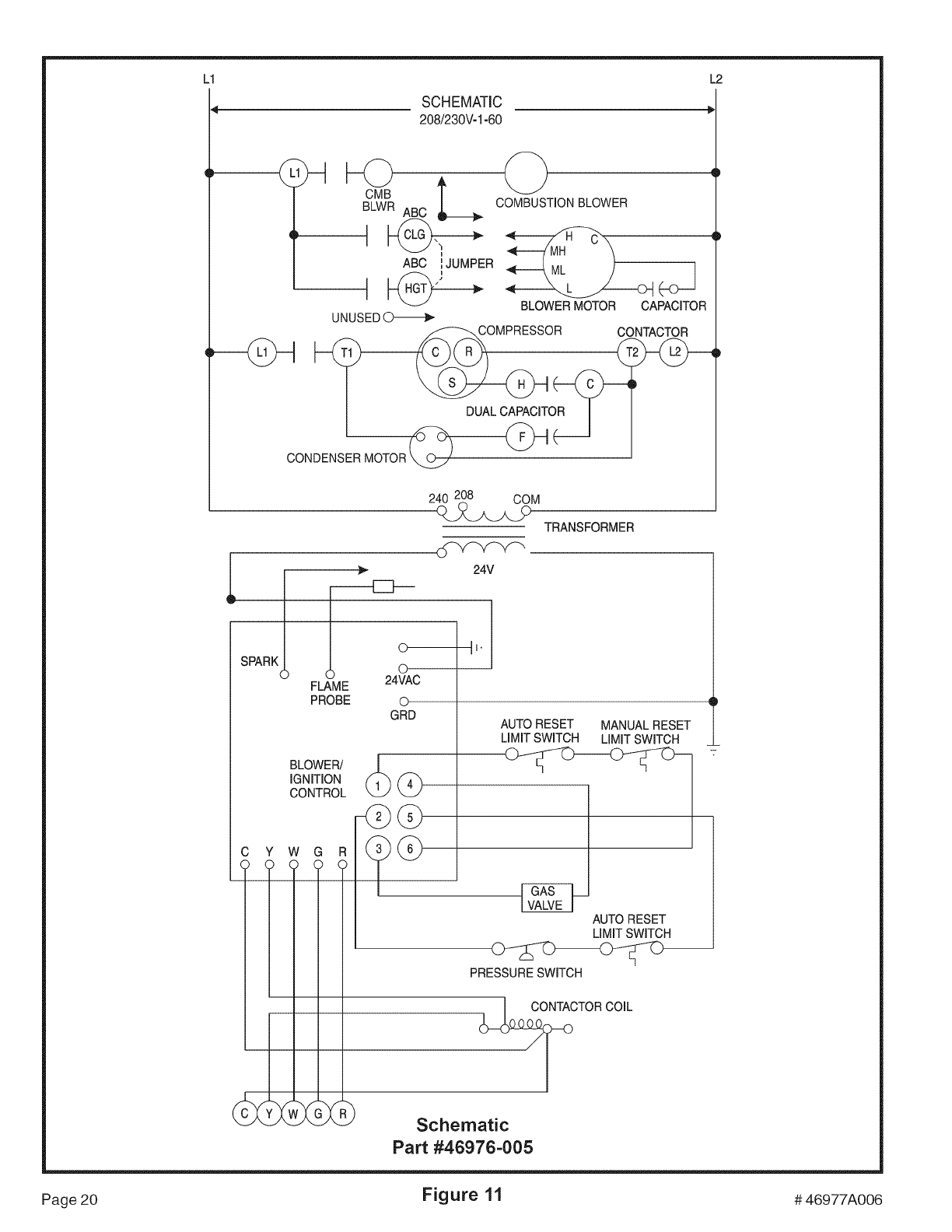
L1 L2
SCHEMATIC
208/230V-1-60
(
COMBUSTION BLOWER
ABC _,JUMPER 1
t _ BLOWER MOTOR CAPACITOR_-J
UNUSED
_COMPRESSOR CONTACTOR
oo_o_s_o_o__
240 208 COM
TRANSFORMER
Is RKI
FLAME 24VAC
O_v_f_ _,
II.
24V
PROBE ©
GRD
BLOWER/
IGNITION
CONTROL
C Y W G R
_G
AUTO RESET MANUAL RESET
LIMIT SWITCH LIMIT SWITCH
AUTO RESET
LIMIT SWITCH
PRESSURE SWITCH
Schematic
Part #46976-005
Page 20 Figure 11 # 46977A006
