Users Manual
ASCC 시스템
1
Advanced Smart Cruise Control System
ASCC 시스템
2
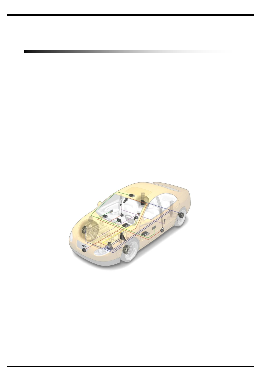
I. System Information
1. Introduction
•The ASCC system operates the convenience feature automatically maintaining the distance by measuring the
distance and speed of the lead vehicle with the radar in front of the car. Also, if the lead vehicle is stopped
along the rear of the lead vehicle stops, and re-start feature provides at the start with Stop & Go function.
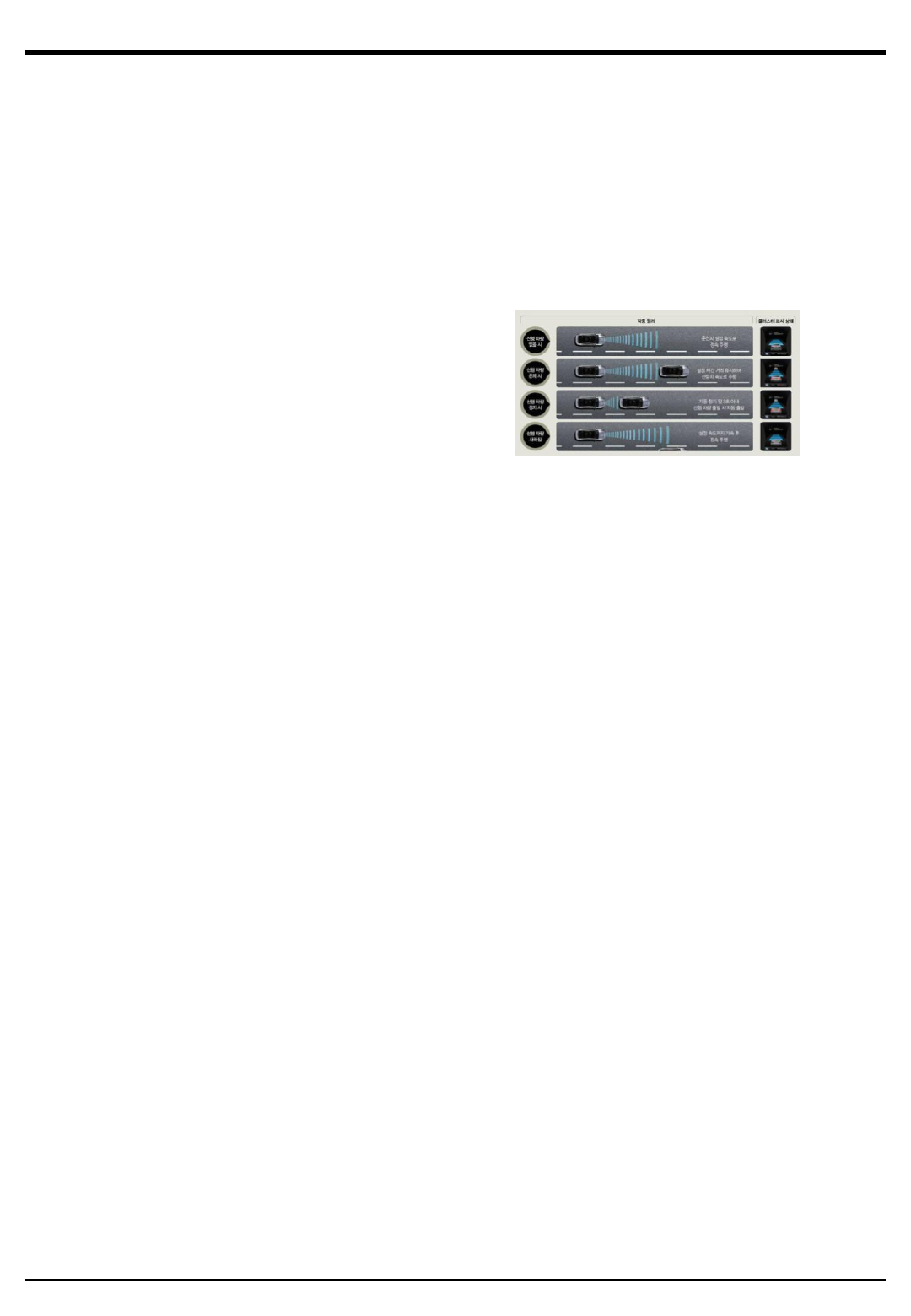
2. System Operation
operation principle
Absence of a lead vehicle
Existing of a lead vehicle
Stopping a lead vehicle
Blinding a lead vehicle
Cluster display state
Cruise control at the driver’s setting speed
Driving the lead vehicle traveling speed maintaining a set following distance
When auto stop and starting the lead vehicle within 3 seconds, automatically start.
Accelerate to the target speed and then cruise control.
1) Normal Mode Control
•All of the speed/distance control can perform from 30 to 180 km/h speed range.
•The minimum target speed is 30km/h.
•If the lead vehicle’s speed is from 0 to 30km/h, the proper distance can be expected(or
calculated/measured).
2) Stop mode Control
•When the lead vehicle is stopped, and then the vehicle would stop at a certain distance.
•If the stop duration is within 3 second, the vehicle automatically start, or not manually the resume/set switch
turn on or the accelerator pedal is pressed. If the stopping maintain more than 5 minutes, the ASCC control
will be released.
3) Overdrive Control
•Driver's accelerator pedal is pressed, the system will give acceleration priority to the judgment of the driver
than the system decision. Then, the driver releasing the accelerator pedal, the target speed gradually slows
down.
4) Overtaking Support Control
•The driver turn on the left blinker, the system internally set as the target distance one-step regardless of
the display condition. Therefore, a slight acceleration can help to occur soft overtaking.
ASCC 시스템
3
II. Specific System Structure
1. SCC
1) Function
•Monitoring front road condition(sensing function)
•Driver riding/getting off and monitoring car condition(ECU function)
•Calculating and output of the Required acceleration(ECU function)
2. Switch
1) Function
•ACSS system On/Off
•Target speed control
•Target distance control
•Operation ON/OFF
•ASCC-CC switching operation
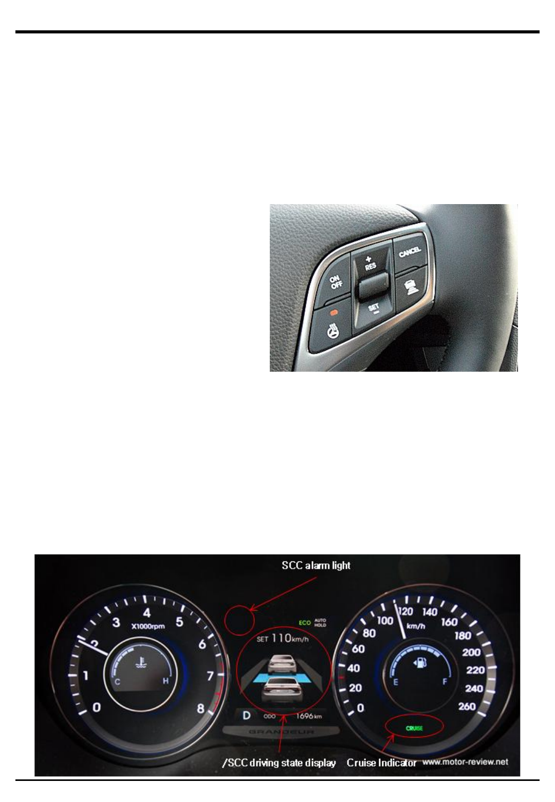
3. Cluster
1) Function
•System On/Off
•System Alarm
•ASCC Operation State (lead vehicle, Break, Overtake, Stop modes) Display
•ASCC Driver Setting State (Target Speed/Distance) Display
•ASCC Auto-unlock/ Usage Condition Un-satisfaction
•ASCC Hazardous situation (lead vehicle breaking, Stop vehicle alert) Display
ASCC 시스템
4
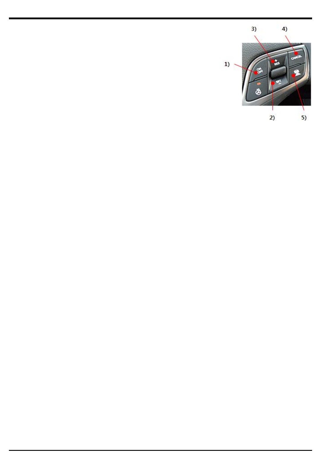
4. Instruction of the ASCC control using switch
1) ON/OFF Main Switch
•ON/OFF function
•In case of the Standby mode, “CRUISE” Ramp turn ON
2) 『SET/– 』 Switch
•At the Stand by mode, Press SET Switch and then Control start.
»The target speed set 30 km/h when the car speed is from 0 to 30 km/h.
»When the car speed is over 30 km/h, the target speed is the same as current speed.
•If the SET switch is pressed under control, the target speed will be decreased.
»Press short period, the speed decrease 1km/h step. ex) 81→80→79→78
»Press long period, the speed decrease at first 1km/h step then 10km/h step. ex) 77→76→70→60
3) 『RES/+』 Switch
•At Standby mode, Press RES+ switch and then control start.
»After the OFF mode changed to Standby mode, the ASCC usage history have to be existed at least once.
•If the RES+ switch is pressed under control, the target speed will be increased.
»Press short period, the speed increase 1km/h step. ex) 77→78→79→80→81
»Press long period, the speed increase at first 1km/h step then 10km/h step. ex) 66→67→70→80
4) 『CANCEL』 Switch
•Released from the control condition
5) 『 Distance setting 』 switch
•Set the target headway distance(Initial value is level.4)
•Press the switch, the target headway distance value changed in the following order.
»level.4->level.3->level.2->level.1->level.4
»In case of the car speed is 90km/h
»At level 1 (1sec.), Headway distance is 25m.
»At level 2 (1.3sec.), Headway distance is 32.5m
»At level 3 (1.6sec.), Headway distance is 40m
»At level 4 (2.1sec.), Headway distance is 52.5m
•If press the switch over 2 sec, the ASCC mode is switched the CC mode each other.
◈ Equipment Specification
Product name LRR-20
Kind of product Automotive Radar
Operating frequency range 76.125 GHz ~ 76.95 GHz
Bandwidth 825 MHz
Type(s) of Modulation
Type(s)
of
Modulation
(e.g. BPSK, FSK, ASK, …) FMCW
Number / Type of Antenna(s) 10(Tx :2 EA, Rx: 8 EA) / patch ANT
Antenna Gain Tx1: 21 dBi, Tx2: 14 dBi, LRx: 18 dBi, SRx: 14 dBi
Intended area of use Automobile
Test sample information production unit
Wired Interfaces CAN/LIN Cable Length: 2 m
Power supply: Battery
Voltages
Vnom : 12 V
Vmax : 16 V
Vmin : 9 V
Current consumption 500 ~ 600 mA
Dimensions (in cm): 101.5 x 77 x 21.5
Wiht
240
1
W
e
i
g
ht
:
240
g

Notice:
ThisdevicecomplieswithPart15oftheFCCRules.Operationissubjecttothefollowingtwoconditions:
(1)thisdevicemaynotcauseharmfulinterference,and
(2)thisdevicemustacceptanyinterferencereceived,includinginterferencethatmaycauseundesiredoperation.
ThisequipmenthasbeentestedandfoundtocomplywiththelimitsforaClassBdigitaldevice,pursuanttopart15oftheFCC
Rules.Theselimitsaredesignedtoprovidereasonableprotectionagainstharmfulinterferenceinaresidentialinstallation.This
equipmentgenerates,usesandcanradiateradiofrequencyenergyand,ifnotinstalledandusedinaccordancewiththe
instructions,maycauseharmfulinterferencetoradiocommunications.However,thereisnoguaranteethatinterferencewill
notoccurinaparticularinstallation.Ifthisequipmentdoescauseharmfulinterferencetoradioortelevisionreception,which
canbedeterminedbyturningtheequipmentoffandon,theuserisencouragedtotrytocorrecttheinterferencebyoneor
moreofthefollowingmeasures:
—Reorientorrelocatethereceivingantenna.
—Increasetheseparationbetweentheequipmentandreceiver.
—Connecttheequipmentintoanoutletonacircuitdifferentfromthattowhichthereceiverisconnected.
—Consultthedealeroranexperiencedradio/TVtechnicianforhelp.
Anychangesormodificationsnotexpresslyapprovedbythepartyresponsibleforcompliancecouldvoidtheauthorityto
operateequipment.
FCCRFRadiationExposureStatement:
ThisequipmentcomplieswithFCCradiationexposurelimitssetforthforanuncontrolledenvironment.
Thisequipmentshouldbeinstalledandoperatedwithminimumdistance20cmbetweentheradiator&yourbody.
LeprésentappareilestconformeauxCNRd'IndustrieCanadaapplicablesauxappareilsradioexemptsdelicence.L'exploitation
estautoriséeauxdeuxconditionssuivantes:(1)l'appareilnedoitpasproduiredebrouillage,et(2)l'utilisateurdel'appareildoit
acceptertoutbrouillageradioélectriquesubi,mêmesilebrouillageestsusceptibled'encompromettrelefonctionnement.
ICRadiationExposureStatement:
ThisequipmentcomplieswithICRSS‐102radiationexposurelimitssetforthforanuncontrolledenvironment.
Thisequipmentshouldbeinstalledandoperatedwithminimumdistance20cmbetweentheradiator&yourbody.
ThisdevicecomplieswithIndustryCanada’slicence‐exemptRSSs.Operationissubjecttothefollowingtwoconditions:
(1)Thisdevicemaynotcauseinterference;and
(2)Thisdevicemustacceptanyinterference,includinginterferencethatmaycauseundesiredoperationofthedevice.
MANDO corp. hereby declares that this Vehicle Radar equipment is in compliance with the essential
requirements and other relevant provisions of Directive 1999/5/EC.
Full doc can be obtained: suhan.kim@halla.com