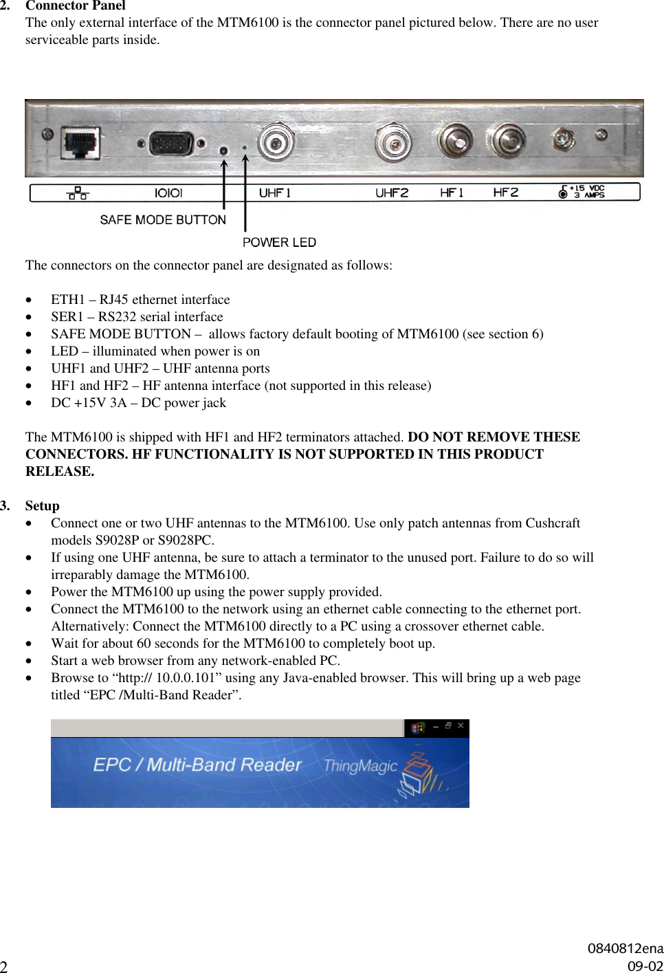
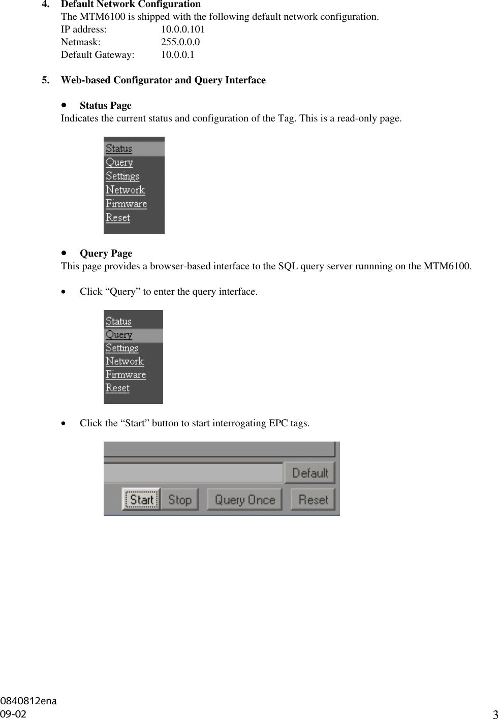
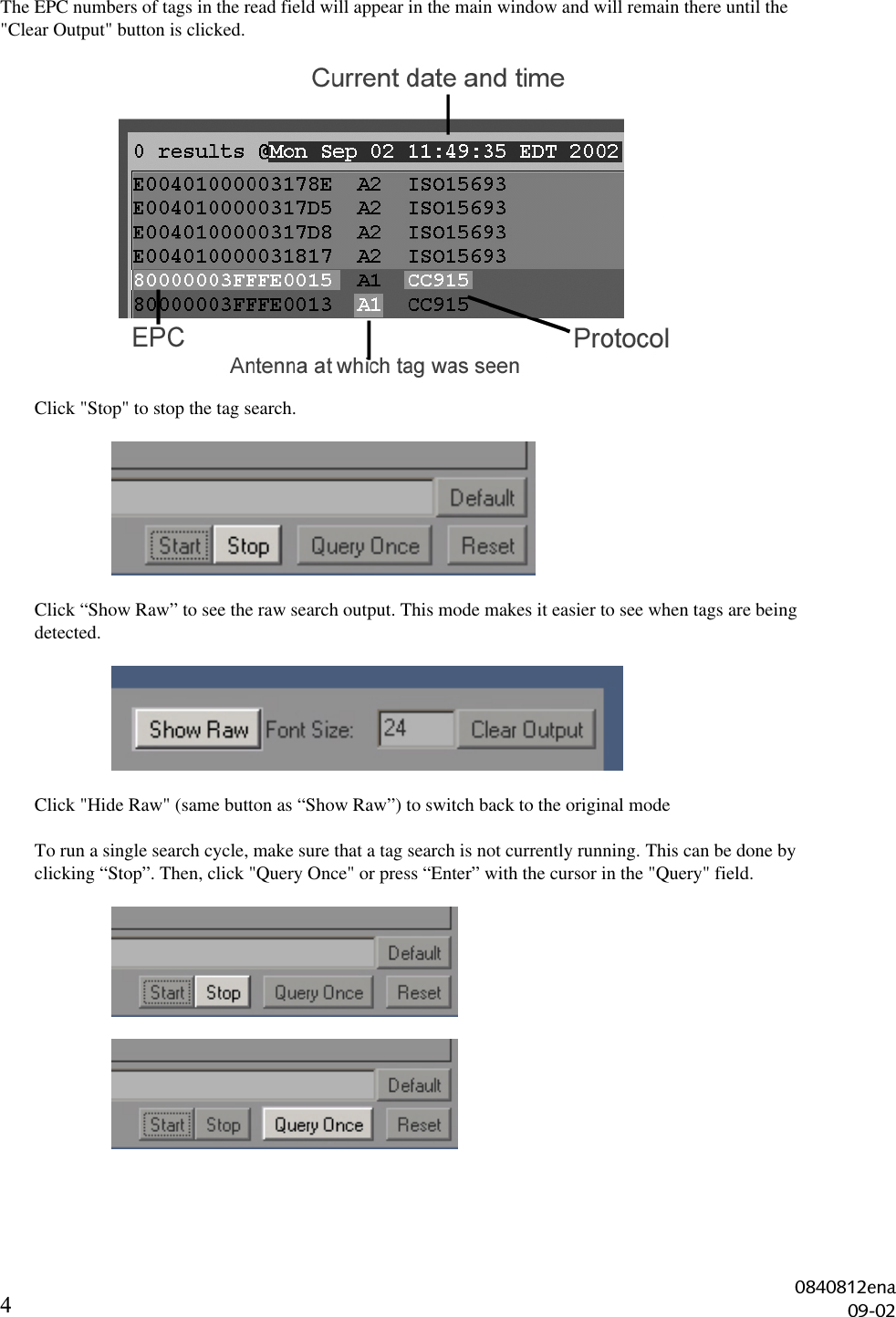
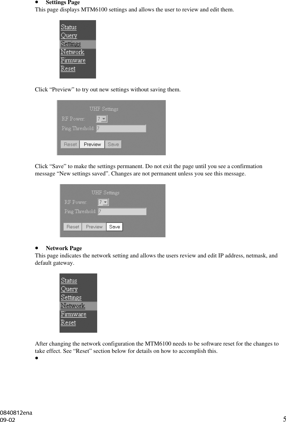
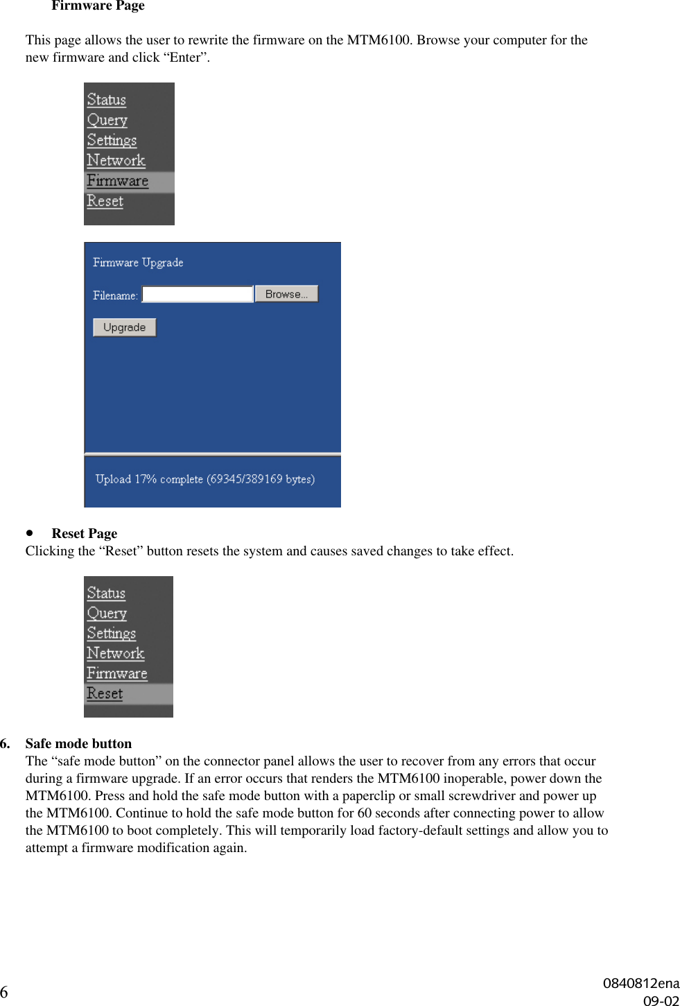
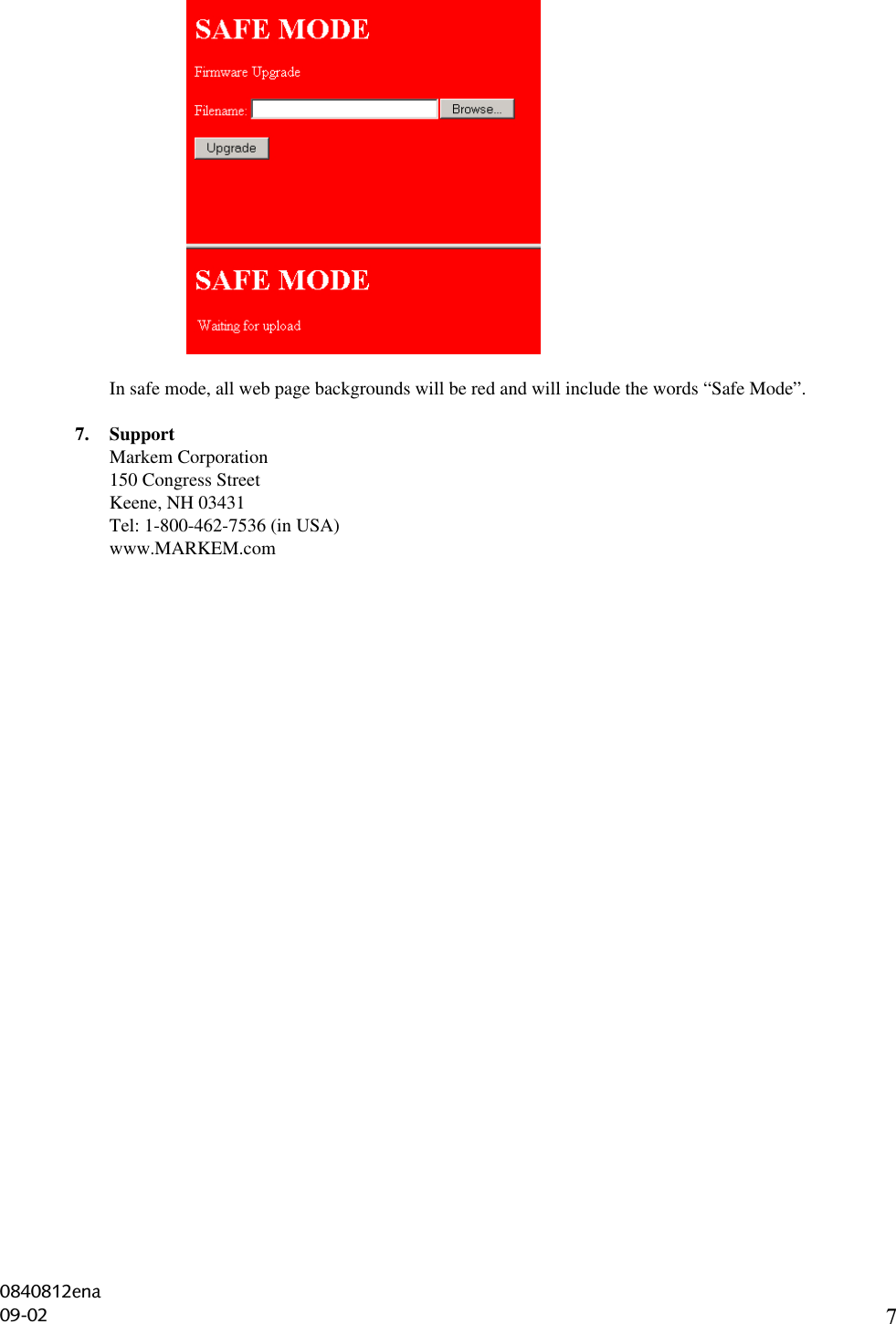
MARKEM MTM6100 RF ID Tag Reader User Manual 0840812

MARKEM Corporation RF ID Tag Reader 0840812

Exhibit D Users Manual per 2 1033 b3

EPC Dual-Band ReaderModel MTM6100Quick Start Guide0840812ena09-02
   ThingMagic/Markem 6100  EPC RFID Reader User Manual Supplement  For Users in the United States  Place this supplement in the User Manual   Federal Communications Commission Compliance NOTE: This equipment has been tested and found to comply with the limits for a Class A digital device, pursuant to part 15 of the FCC Rules. These limits are designed to provide reasonable protection against harmful interference when the equipment is operated in commercial environment. This equipment generates, uses, and can radiate radio frequency energy and, if not installed and used in accordance with the instruction manual, may cause harmful interference to radio communications. Operation of this equipment in a residential area is likely to cause harmful interference in which case the user will be required to correct the interference at his own expense.   Antenna Installation It is required that the antenna assembly of this device be installed in accordance with the installation procedures in the manual, in order to comply with the regulations below.  Installation Warning FCC regulations limit exposure to radio frequency (RF) radiation. To comply with these regulations, this device must be installed in such a way that the installers of this device will not be closer to 20cm from the cover of the UHF antennas under normal installation conditions. While the device is operating the installer’s body and parts of the installer’s body such as eyes, hands, or head must be 20cm or farther from the cover of the UHF antennas.   Operator Warning FCC regulations limit exposure to radio frequency (RF) radiation. To comply with these regulations, this device must be installed in such a way that the operators of this device will not be closer to 20cm from the cover of the UHF antennas under normal operating conditions. While the device is operating the operator’s body and parts of the operator’s body such as eyes, hands, or head must be 20cm or farther from the cover of the UHF antennas.
    Unaware Persons Warning FCC regulations limit exposure to radio frequency (RF) radiation. To comply with these regulations, this device must be installed in such a way that unaware persons will not be closer to 20cm from the cover of the UHF antennas under normal operating conditions. While the device is operating unaware persons and parts of the unaware person’s body such as eyes, hands, or head must be 20cm or farther from the cover of the UHF antennas.   Caution Changes or modifications to the device or installation not expressly approved by Markem Corporation could void the user's authority to operate this device.
1EPC Dual-Band Reader Model MTM6100Please read this document in its entirety before attempting installation of the MTM6100. It is important thatyou fully understand the installation procedure  before powering up the MTM6100.WARNINGDO NOT POWER UP THE MTM6100 IF ANY ANTENNA PORTS ARE UNCONNECTED. BOTHHF ANTENNA PORTS SHOULD HAVE TERMINATORS CONNECTED TO THEM AND  BOTHUHF PORTS SHOULD HAVE EITHER ANTENNAS OR TERMINATORS CONNECTED TOTHEM.MAKE SURE THAT ANTENNA CONNECTORS AND THE TERMINATORS ARE FIRMLYATTACHED.FAILURE TO FOLLOW BOTH THESE WARNINGS WILL CAUSE IRREPARABLE DAMAGETO THE MTM6100.1. Packing ListPlease check the package to make sure it includes the following items:• EPC Dual-Band Reader model MTM6100• 15 V DC 3A power adapter• 2 HF terminators (attached to the HF ports on the connector panel)• 2 UHF terminators  (attached to the UHF ports on the connector panel)• Quick Reference Guide (this document)• FCC Manual Supplement (please read this carefully)Visually inspect the items. If any items are incorrect, missing, or appear to be damaged, please contactthe MARKEM representative listed at the end of this document. Please retain all packing material incase you need to return the MTM6100.Required components which are not included in the package:• Cushcraft UHF patch antenna model numbers S9028P or S9028PC with a 12 foot custom RFcable and a reverse polarity TNC connector.  (Use only these antennas with the MTM6100)FCC regulations require that care be taken to limit exposure to radio frequency radiation. Pleaseconsult the FCC Manual Supplement for important safety and compliance information.0840812ena09-02
22. Connector PanelThe only external interface of the MTM6100 is the connector panel pictured below. There are no userserviceable parts inside.The connectors on the connector panel are designated as follows:• ETH1 – RJ45 ethernet interface• SER1 – RS232 serial interface• SAFE MODE BUTTON –  allows factory default booting of MTM6100 (see section 6)• LED – illuminated when power is on• UHF1 and UHF2 – UHF antenna ports• HF1 and HF2 – HF antenna interface (not supported in this release)• DC +15V 3A – DC power jackThe MTM6100 is shipped with HF1 and HF2 terminators attached. DO NOT REMOVE THESECONNECTORS. HF FUNCTIONALITY IS NOT SUPPORTED IN THIS PRODUCTRELEASE.3. Setup• Connect one or two UHF antennas to the MTM6100. Use only patch antennas from Cushcraftmodels S9028P or S9028PC.• If using one UHF antenna, be sure to attach a terminator to the unused port. Failure to do so willirreparably damage the MTM6100.• Power the MTM6100 up using the power supply provided.• Connect the MTM6100 to the network using an ethernet cable connecting to the ethernet port.Alternatively: Connect the MTM6100 directly to a PC using a crossover ethernet cable.• Wait for about 60 seconds for the MTM6100 to completely boot up.• Start a web browser from any network-enabled PC.• Browse to “http:// 10.0.0.101” using any Java-enabled browser. This will bring up a web pagetitled “EPC /Multi-Band Reader”.0840812ena09-02
34. Default Network ConfigurationThe MTM6100 is shipped with the following default network configuration.IP address: 10.0.0.101Netmask: 255.0.0.0Default Gateway: 10.0.0.15. Web-based Configurator and Query Interface• Status PageIndicates the current status and configuration of the Tag. This is a read-only page.• Query PageThis page provides a browser-based interface to the SQL query server runnning on the MTM6100.• Click “Query” to enter the query interface.• Click the “Start” button to start interrogating EPC tags.0840812ena09-02
4The EPC numbers of tags in the read field will appear in the main window and will remain there until the"Clear Output" button is clicked.Click "Stop" to stop the tag search.Click “Show Raw” to see the raw search output. This mode makes it easier to see when tags are beingdetected.Click "Hide Raw" (same button as “Show Raw”) to switch back to the original modeTo run a single search cycle, make sure that a tag search is not currently running. This can be done byclicking “Stop”. Then, click "Query Once" or press “Enter” with the cursor in the "Query" field.0840812ena09-02
5• Settings PageThis page displays MTM6100 settings and allows the user to review and edit them.Click “Preview” to try out new settings without saving them.Click “Save” to make the settings permanent. Do not exit the page until you see a confirmationmessage “New settings saved”. Changes are not permanent unless you see this message.• Network PageThis page indicates the network setting and allows the users review and edit IP address, netmask, anddefault gateway.After changing the network configuration the MTM6100 needs to be software reset for the changes totake effect. See “Reset” section below for details on how to accomplish this.• 0840812ena09-02
6Firmware PageThis page allows the user to rewrite the firmware on the MTM6100. Browse your computer for thenew firmware and click “Enter”.• Reset PageClicking the “Reset” button resets the system and causes saved changes to take effect.6. Safe mode buttonThe “safe mode button” on the connector panel allows the user to recover from any errors that occurduring a firmware upgrade. If an error occurs that renders the MTM6100 inoperable, power down theMTM6100. Press and hold the safe mode button with a paperclip or small screwdriver and power upthe MTM6100. Continue to hold the safe mode button for 60 seconds after connecting power to allowthe MTM6100 to boot completely. This will temporarily load factory-default settings and allow you toattempt a firmware modification again.0840812ena09-02
7In safe mode, all web page backgrounds will be red and will include the words “Safe Mode”.7. SupportMarkem Corporation150 Congress StreetKeene, NH 03431Tel: 1-800-462-7536 (in USA)www.MARKEM.com0840812ena09-02

Navigation menu