MARKTRACE MR61XX UHF RFID Reader User Manual Ver 1 2
SHENZHEN MARKTRACE CO., LTD. UHF RFID Reader Ver 1 2
Users Manual

MR6100 Serial
UHF Reader User Manual
SHENZHEN MARKTRACE CO., LTD.

Dear Customer:
Many thanks for bought Marktrace device.
Go through precuts user manual carefully before you
operate. To make sure Marktrace device work correct. Any
questions, please contact us. We welcome your feedback and
comments.
SHENZHEN MARKTRACE CO., LTD.
MR6100 Serial UHF reader User
Manual

(Ver1.2)
Disclaimer
Martkrace reserve the right to update and modify this user manual. For the
new documents may has no further notice.
Don’t tear up the warranty label or take reader apart to repair by yourself, we
reject perform warranty duties if this happened.
Shenzhen Marktrace Co.,Ltd have trademark right on the trademark which in
this user manual and receive legal protection. DO NOT make free with theses
trademarks.
®
Customer Service Center
Phone:400-022-3382 0755-2654 6392/2654 4205
Fax:0755-2655 3743
E-mail:technical@ marktrace.com
Website:http://www.marktrace.com
Post:518057

1 Matters need attention
1、 Dismantle and parts replace:Marktrace has no warranty duties on those
faults which caused by dismantle and parts replace by customer .;
2、 Power supply:please use the power adaptor which alone with precuts to
get power. If not may harm the products.;
3、 Falling damage:Mind parts damage by device falling, if this happens, turn
off power immediately and connect the distributor or Marktrace customer
service center.;
4、 Unusual condition:Away from fire. If you find unusual odor when you use
this products, or reader on overheating or emitting smog, please power off
immediately and drop plug form the plug seat. You can connect the
distributor or Marktrace customer service center for helps. If you continue
to use this device, may cause the danger of fire or electronic shock.;
5、 Place:Don’t place device on the site which is not level, mind damage or
personal injury on falling.
2 Reader instruction
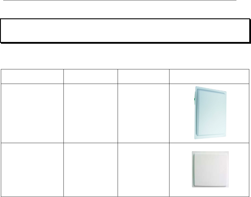
2.1 MR6100 Serial UHF reader introduction
Model Description Parameter Photo
MR6111E
Long range
integrated
reader
12dBi Gain
antenna
inside
MR6121E
Mid-range
integrated
reader
9dBi Gain
antenna
inside
2.2 Reader instruction
This products has the features like multi protocol compatible, multi-tag identify,
multi-tag multi area read and write, fast reader speed, can connect to four
antennas etc.:
1、 Accord with ISO18000-6B and ISO18000-6C(EPC-GEN2) standard;
2、 Use unique anti-collision algorithm,has the super multi-tag identify ability;
3、 Have tag identify function and data area read, write, lock and kill these
functions. And supply the suit API to customer to do secondary
development.;
4、 Multi-tag identify ability:The MAX reader range can reach 8 meters.
(working with 7dBi gain antennas),can connect the different gain
antennas like 9dBi、12dBi etc,can identify the tag which moving speed is
120km/h correctly.;

5、 Tag identify speed : Single tag 2000 times/minute ,multi-tag
200pcs/second;
6、 Have RS232、RS485、 Weigand、TCP/IP、Relay etc output interface;
7、 Compatible with tag match function,Reader can identify the tag which
match the condition or not identify these condition tags by setting the
match conditions.;
8、Compatible with data cache function, Using FRAM (ferroelectric memory)
which can save data when power down,memory capacity is 32KBytes,
Can save 2200 pcs tag data in 12 Bytes data length.
2.3 Reader applications
This reader can used in items identification and data collecting project. As the
best performance of this reader, the reader are widely use in various RFID
system,reference application as below:
1, Transportation management: highway management, railway management
and container management etc.
2, Motor vehicle management: can control and manage motor vehicle in
Ministry of Public Security or Ministry of Communications.
3, Rode and bridge charge management: As this reader have the ability of
collecting tag data in long range distance, can used in rode and bridge ETC
system.
4, Customs declare management: custom declare, goods transfer and vehicle
management.
5, Logistics and warehouse Management: Goods flow, warehouse
management, and the flowing management of mail, parcel, luggage.
6, Productive lines Management: Production process fixed Identify or
technological process control.
2.4 Reader main functions
1、 Read tag data:Can read multi-tag same area and same data length in a

same time;
2、 Write tag:Can write the same data length in multi-tag’s same area.;
3、 Tag match:Can read match tag or dismatch tag via setting the match
conditions;
4、 Make data communicate and change with the connection between
standard communication interface and controller or PC,;
2.5 Reader technical parameter
1、 CompatibleISO18000-6B and ISO18000-6C(EPC-GEN2) protocol
standard;
2、 Working frequency:fixed-frequency can choose ISM 902~928MHz
(America)、stepped frequency is 500KHz;modulation mode is ASK.
3、 Trigger working mode:Timer and I/O can trigger reader,Timer interval
from 10-990ms;I/O trigger MAX time is 255s;
4、 Data pre-processing:On trigger working mode,Tag data can store in
cache or output directly.;
5、 Data cache:Trigger working mode data cache using FRAM (ferroelectric
memory) which can save data when power down,memory capacity is
32KBytes,Can save 2200 pcs tag data in 12 Bytes data length;
6、 Data output:Data return by instant messaging,Can config RS232、RS485、
Weigand、TCP/IP、Relay interface, Can config output data length and start
address,Output data format in ASCII;
7、 Compatible ISO18000-6C tag match function ,match tag by setting
conditions;
8、For ISO18000-6B tag. Can do read, write, lock and identify operate to single
tag one byte ,can read and write specific tag data with UID;
9、Working voltage:DC+9V~+15V;
10、Working temperature:-20℃~+60℃;
11、Storage temperature:-40℃~+85℃;
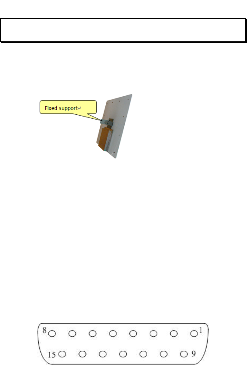
3 Reader Structure and Interface Explanation
3.1 Reader Structure Explanation
1、 MR6111E、MR6121E integrated reader structure explanation
3.2 Explanation on the reader communication interface
1. RS232: the Reader provides standard RS232 communication interface as
the output port for data modulation. RS232 has 8 data bits format: 1 start bit
and 1 stop bit, no parity bit. The default baud rate is 115200 bps. The
interface supports the reader parameters configuration, software upgrading,
demo program and all functions for series communication with
development kit with functions package;
2. RJ45(Ethernet Port):100M Ethernet,TCP Server Mode; It is main mode
for connecting communication with PC,also can be data output main
mode ,The interface supports the reader parameters configuration,
software upgrading, demo program and all functions for TCP/IP
communication with development kit with functions package;
3. Data Interface DB15 diagram and pin definition
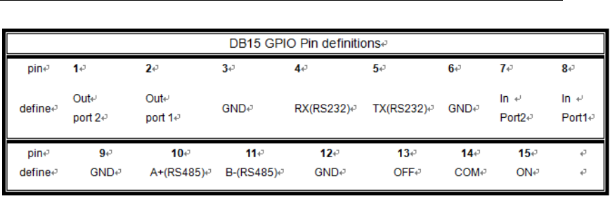
4. RS485:Reader provide RS485 communication interface(10、11 pin),
work as data main output mode,also can connect with PC via serial port,
use RS232-RS485 converter,in this way,RS485 interface support RS232
all supported functions;
5. Programmable output interface :Two sets TTL electrical level
programmable output interface(1、2 pin),works as Wiegand output
interface,default is high level(5V);one set relay interface(13、14、15
pin),relay default status is OFF and COM short circuit
6. Input check port:2 team input check port(7、8 pin),can configure as trigger
read mode,default as Dangling status is high level(5V);
7. Power supply port:DC+9V~+15V==4A power port;
8. Antenna port:4 sets TNC antenna port;
9. Indicator light:6 indicator light,including COM port indicator light、power
indicator light and 4 sets antenna indicator light;
4 Quick Start Guide
1、 Connect antenna to reader’s antenna port,connect power adapter to
reader and then power on,connect reader to LAN or PC by network cable;
2、 In PC open demo software“MR6100 Demo V1.0”,fill in reader IP address
and click“Connect”to connect reader(reader factory default IP address:
192.168.1.200);
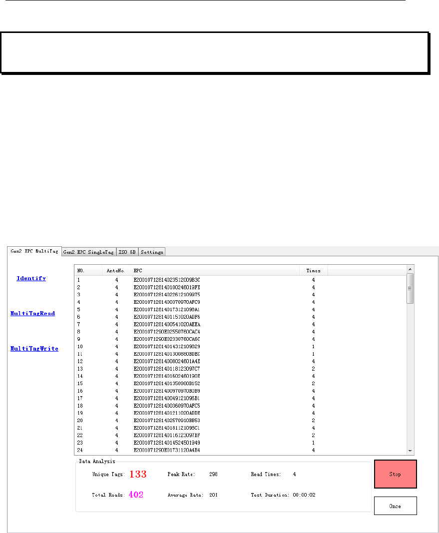
3、 In“Gen2 EPC MultiTag” page,click bottom right corner“Identify”button will
start EPC tag query operation,see below:
5, Click “Stop” button to Stop identify operate.
5 Reader parameter configuration
5.1 Webpage configuration
Reader connect to LAN through TCP/IP port,or directly connect PC,in PC
IE browser input reader IP address (reader factory default IP address:
192.168.1.200),after running then open WEB page as below:
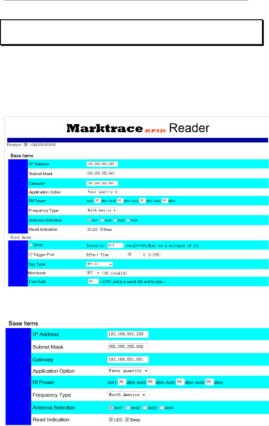
Can be configure as below:
1、Basic Item configuration
1)User can configure IP address、RF power、frequency、antenna port、applied
mode、read card indicating etc.,
2)Each antenna port RF power can be configurable, range: 0-31dBm;
3)Frequency standard: China Frequency、US Frequency、EU Frequency
three type standard hopping frequency selectable;
4)Applied mode:“Favor speed” and“Favor quantity” two mode
selectable“Favor speed” for single tag or small batch tags quick speed read
mode;
“Favor quantity”for big batch tags read mode;
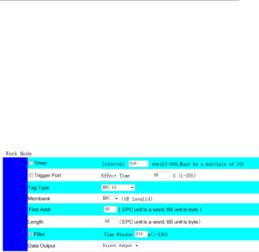
2、Operating mode configuration
1)In operating mode configuration, user can configure reader to be timming
working mode or pin trigger working mode,timer’s timing interval can be
configure between 10-990ms;When in trigger working mod, reading
maximum lasting time can be configure as 255s;
2)Read tag type can be 18000-6B or EPC G2,also can be configure read both
at same time(expand function);
3)When read EPC tag,read area can select as EPC、TID or USER memory;
6B tag cannot select area;
4)User can select read tag’s start address and read data length,EPC tag data
use word as unit,6B tag data use byte as unit;
5)User filter repeat tag,Filter set one slide time window,only new data which
not show in box can be buffer or direct output;
6)Read tag data can be select buffer or directly output,data buffer adapt with
power down save ferroelectric memory,storage capacity 32KBytes,when read
data length is 12Bytes,can store more than 2200pcs tag data;
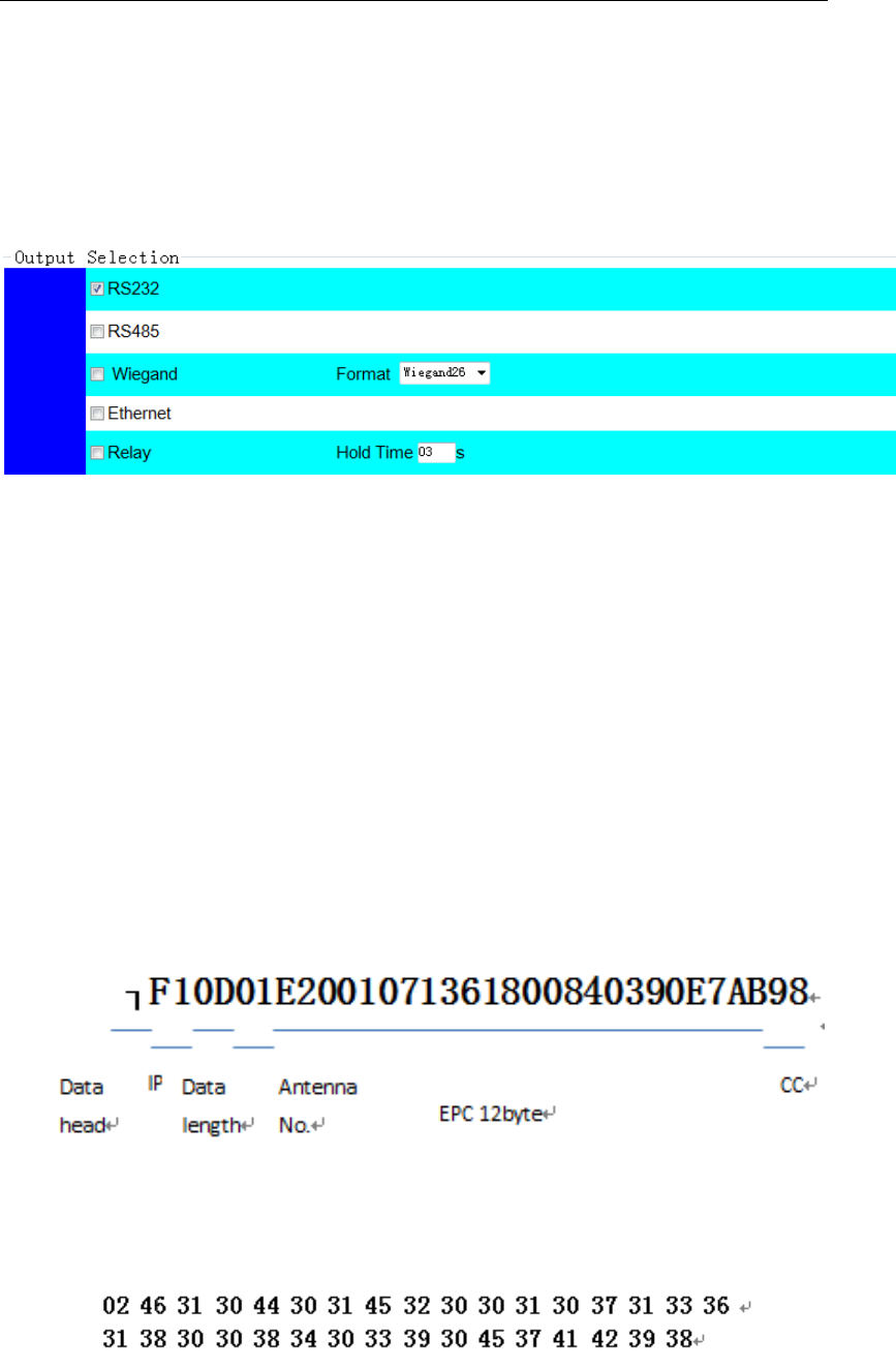
3、output configuration
1)In working mode configure, when select data output as directly output mode,
user can configure output port;
2)Reader data output port have RS232、RS485、Wiegand、Ethernet and relay
output;
3)Wiegand protocol support Wiegand26 and Wiegand34;
4)Relay close delay time configurable between 0-99s;
5)For above mentioned port, user can select one type or multiple type to
output data;
6)Data output can in ASCII code and Hex format;data format see below:
ASCII Code Format
Hex Format
All above configuration will be valid only after click left bottom
button“set” button
5.2 Demo software Configuration
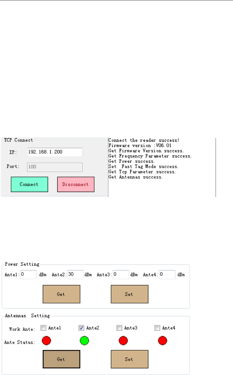
5.2.1 Reader connection
Click MR6100Demo.exe software, input reader’s IP into the IP input box
(Default IP: 192.168.1.200, Port: 100 which is fixed), then click ‘connect’ ICON,
software information display box will display the reader’s parameter on the
success connection. Below image demonstrate the success connection.
5.2.2 Antenna & RF Power setting
1 On MR6100Demo.exe software’s Setting interface, query and set Antenna’s
RF Power on Power setting; Query and set Antenna on Antennas Setting. Take
below image for the reference.
2、Set the 4 antenna ports RF power separately from the range of 0 to 31dBm.
3、On the reader connection, the antenna port will begin self detection, and the
connecting Antenna port is on GREEN ICON, Disconnecting Antenna port is
on RED ICON. Only the selected GREEN ICON port’s antenna works.
2、 On Integrated RFID reader and Desktop RFID reader, config and set one
antenna port for the reader to work.
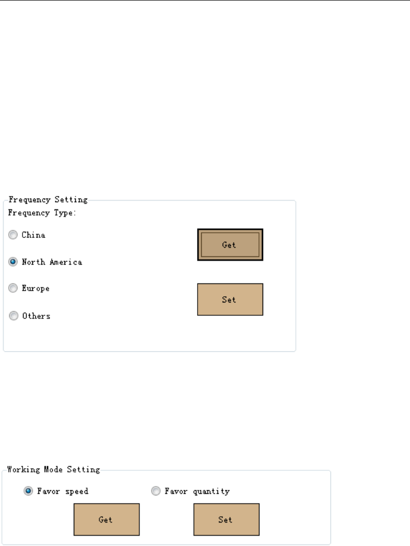
5.2.3 Frequency Setting
On MR6100Demo.exe software's Setting interface, Query Reader’s
Frequency on Frequency setting menu, North America Frequency
(902-928MHz). Take below images for the reference.
5.2.4 Working Mode Setting.
1、On setting interface’s Working Mode Setting, there are two working mode,
Favor speed and Favor quantity for the query and setting, take below image for
the reference.
2、Favor speed is for single tag or few tags reading with the high speed tag
reading rate. Favor Speed working mode is configurated for the applications
require high speed tag reading rate (e.g. Not-stop Highway toll)
Favor Quantity is for the multi and tense tags reading, Favor Speed working
mode is configurated for the applications (e.g. warehouse, logistic)
3、If the reader is configurated into Favor speed working mode, it’s invalid for
the Matched EPC tag reading.
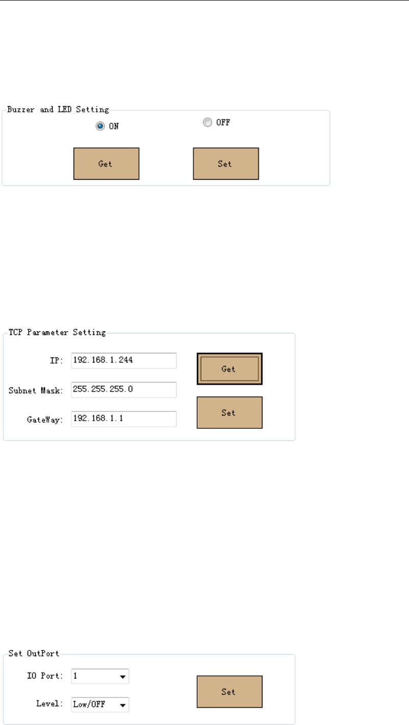
5.2.5 Buzzer & LED Setting
1、On Setting interface’s Buzzer & LED Setting menu for Querying and Setting
Buzzer & LED ON/OFF. Take below image for the reference.
2、After setting Buzzer & LED ON/OFF, Reader automatically reset, and need
to reconnect the reader.
5.2.6 IP Address Setting
1、On setting interface’s TCP Parameter Setting menu for querying and setting
reader’s IP, take below image for the reference.
2、Reader automatically reset when set a new IP address, and need to
reconnect the reader with new IP address
5.2.7 GPIO Setting
On Setting interface’s Set Out Port menu for the reader output port setting.
The reader has two sets output port and one set Relay port. IO Port0 and IO
Port1 are output port with default High level voltage (5V) and Low level voltage
(0V) configurable. IO port2 is Relay output port with default OFF setting. take
below image for the reference.
6 Demo software demonstration
6.1 EPC Gen2 tag Demonstration
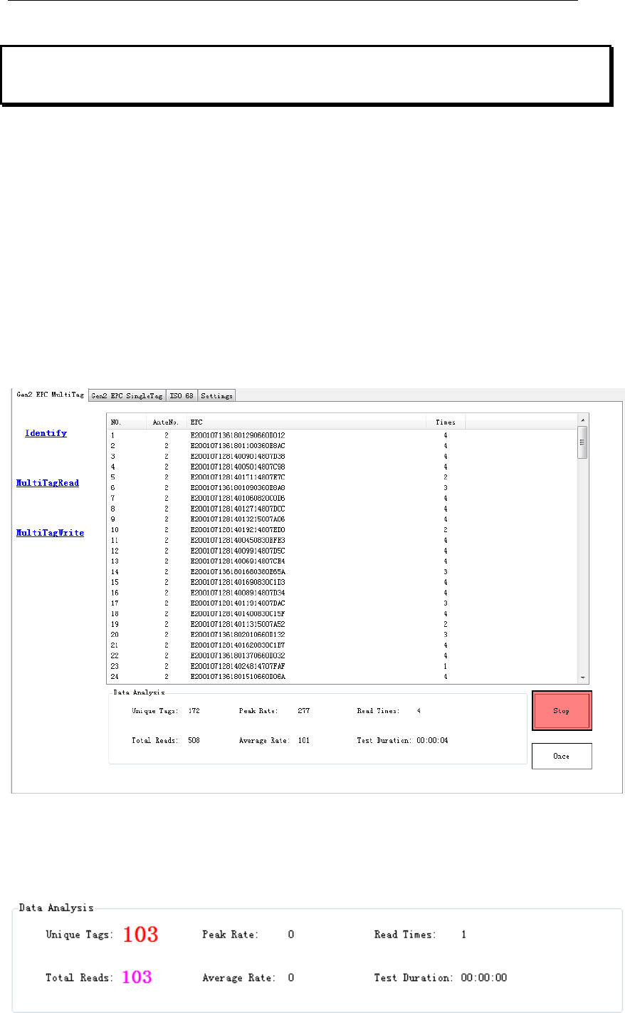
6.1.1 Multi tag Identify
1、On Gen2 EPC Multi Tag interface’s Identify menu for the Multi tag identify,
and click Identify ICON to start the reading. EPC code, antenna number and
tag reading times displayed on the interface info. box. On the interface bottom
displays tag number, Peak reading rate, Read times, total reads, Average
reading rate, and duration reading time. Take below image for the reference.
2、Click ‘Stop’ ICON for stopping tag identify.
3、Click ‘ Once’ ICON for sending once tag detect command, and returns the
tag number, take below image for the reference.
6.1.2 Multi Tag Read & Write
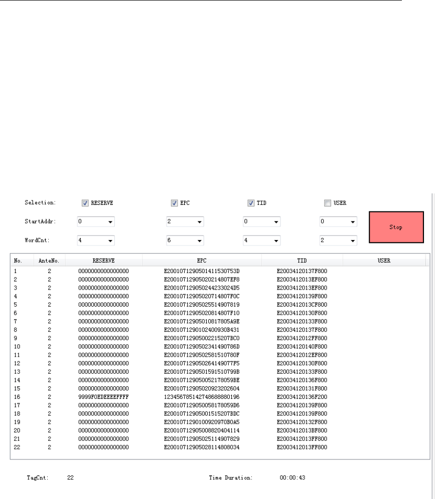
1、On Gen2 EPC Multi Tag interface’s Multi Tag Read menu for the Multi tag
read, Multi tag reader is read tag’s RESERVE Membank, EPC Membank, TID
Membank & USER Membank at the same time. The steps are: 1) select the
reading Membanks, 2) select the start reading address and the reading word
count (EPC tag’s unit is word), and then click ‘Read’ ICON to start the Multi-tag
reading. Take below image for the reference.
2、Click ‘Stop’ ICON to stop Multi-tag reading, at the bottom of the demo
software interface display the tag number, and the reading duration time.
3、On Gen2 EPC Multi Tag interface’s Multi Tag Write menu for Multi tag
encoding. Multi-Tag Write is to encode the tag’s Reserve Membank, EPC
Membank, and USER Membank at the same time. The steps are: 1) select the
encoding Membank, 2) select the tag start encoding address and the encoding
word count (EPC tag’s unit is word), 3) input the encoding value, then click
‘Write’ ICON to encoding the multi-tag. Take below image for the reference.

4、Click ‘Stop’ ICON to stop the Multi-Tag encoding, at the bottom of the demo
software display the Success encoding tag number, and tag encoding duration
time.
5、In accordance with the EPC Protocol, On Multi Tag Read & Multi Tag Write,
EPC Membank’s Start reading address and Start encoding address is from the
EPC Membank’s Second word address.
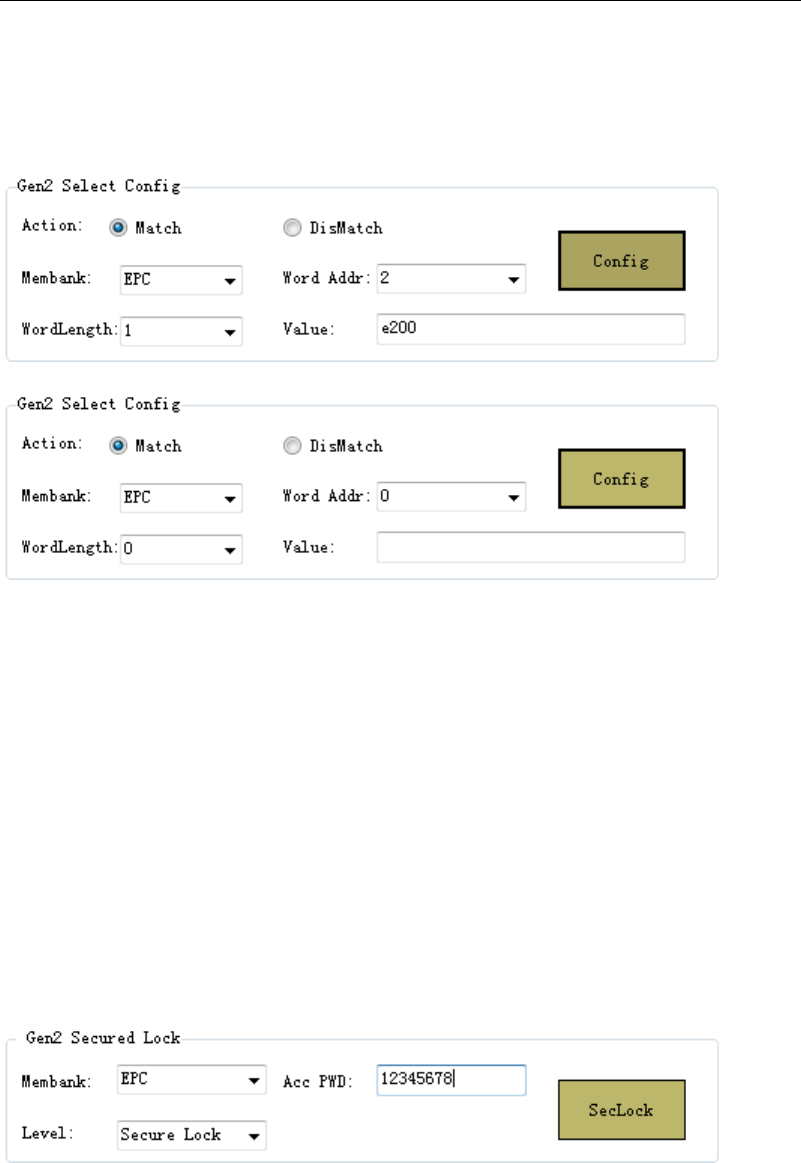
6.1.3 Tag Filter
On Gen2 EPC Single Tag interface’s Gen2 Select Config menu for the Tag
Filter rule setting. Tag Filter setting rule is based on the EPC Membank, TID
Membank or USER Membank value for the setting condition. In accordance
with the EPC Gen2 Protocol, RESERVE Membank’s data is invalid for the tag
filter rule setting. Please 1) select the EPC tag Membank, 2) the word addr. 3)
Word Length, 4) Input the value, then Click ‘Config’ ICON for the Tag filter rule
setting.
1、Only on Favor quantity working mode, the Tag filter setting is valid, on Favor
speed working mode, tag filter setting is invalid.
2、Match setting, reader reads and displays only the condition matched tag.
3、Mismatch setting, Reader doesn’t read and display the condition matched
tag.
4、Empty the input value for cancel the Tag filter rule.
5、If setting EPC Membank as the Tag filter rule, the valid Word Addr is 2.
6、After set the EPC tag filter rule, this rule is valid for all EPC tag detect.
7、After set the EPC tag filter rule, this rule is valid for all the time unless the
reader is power off or reset.
6.1.4 EPC Gen2 Tag Lock
1、On Gen2 EPC Single Tag interface’s Gen2 Secured Lock menu for the EPC
Gen2 Tag Lock setting. With Access Password, it can lock Reserve Membank,
EPC Membank, and USER Membank in different lock level. Take below image
for the reference.
2、EPC Gen2 Tag Lock level are unlock, unlock forever, and secure lock, lock
forever
1)Unlock means the tag is not to encrypted the tag
2)Unlock forever means the tag will not be locked forever
3)On Secure Lock, RESERVE Membank only can be read and write with
Access Password, EPC Memban and USER Membank can be encoded
with Access Password.
4)Lock forever, if the tag is set to lock forever, it can’t be unlock again.
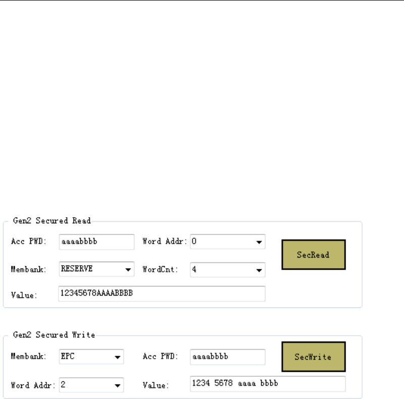
6.1.5 EPC Gen2 Tag Read and write with Access Password
1、n Gen2 EPC Single Tag interface’s Gen2 Secured Read and Gen2 Secured
Write menu for the EPC tag reader and write with Access password. Take
below image for the reference.
1)Gen2 Secured Read with Access password
2)Gen2 Secured Write with Access password.
2、EPC Gen2 Secured Read with Access password need to input the Select
Read tag’s Word Addr, and the WordCnt.
3、EPC Gen2 Secured Write with Access password need to input the Select
Write tag’s Word Addr, and the WordCnt
4、Secure locked Reserve Membank can only be read & write with Access
Password, Secure Locked EPC Membank and Secure Locked USER
Membank can be encoded with Access Password, while can read without the
Access Password.
5、 In accordance with the EPC Protocol, TID Membank can’t be locked,
Access Password is invalid for TID Membank.
6.1.6 EPC Gen2 Tag Kill.
1、On Gen2 EPC Single Tag interface’s Gen2 Kill menu for the Tag Kill
password to kill the tag, Take below image for the reference.
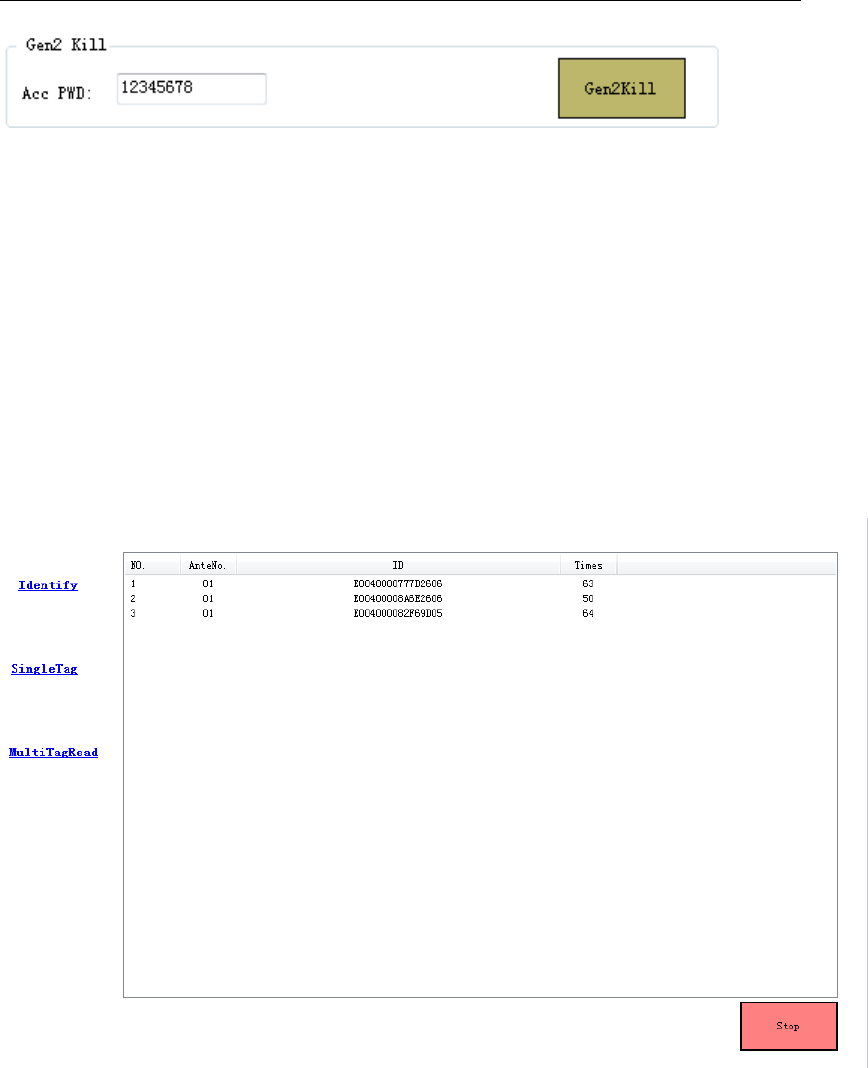
2、EPC Gen2 tag can’t be read and write if the tag is killed.
6.2 ISO18000-6B Protocol tag Demonstration
6.2.1 ISO18000-6B tag Identify
On ISO 6B interface for the ISO18000-6B tag Identify. Click ‘Identify’ ICON
for the tags Identify, and the software interface displays the ISO18000-6B tag’s
UID code, Antenna No., and the read times. Click ‘Stop’ ICON for stoping the
tag Identify. Take below image for the reference.
6.2.2 Multi-tag user data reading
Put several 6B tags in the radiation range of antenna,in the ISO 6B
operation interface,choose Multi Tag Read to enter into multi-tag data reading
interface ,choose the start address of data that you want to read,then
click“Read”button to operate multi-tag data reading,the interface will indicate 8
bytes data from start address、antennas numbers and times to be read,like
following picture indicates,click“Stop”button to stop user data reading;
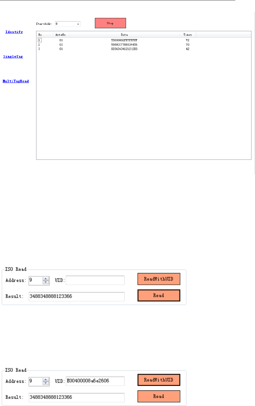
6.2.3 Single tag data reading and read with UID
1、In the ISO 6B operation interface,choose Single Tag to enter into single
tag operation interface,choose the start address of data you want to read in
the ISO Read menu item,click“Read”button to start reading data,the
interface will indicate the tags data that is read,the data length is 8 bytes data
from start address:
2、When data read with UID,it needs to know the UID of the tag first,you can
set the start address to 0 when query UID,the reading data is tag UID,after
inputting UID,choose the start address of reading data,click“Read With
UID”button to operate data reading:
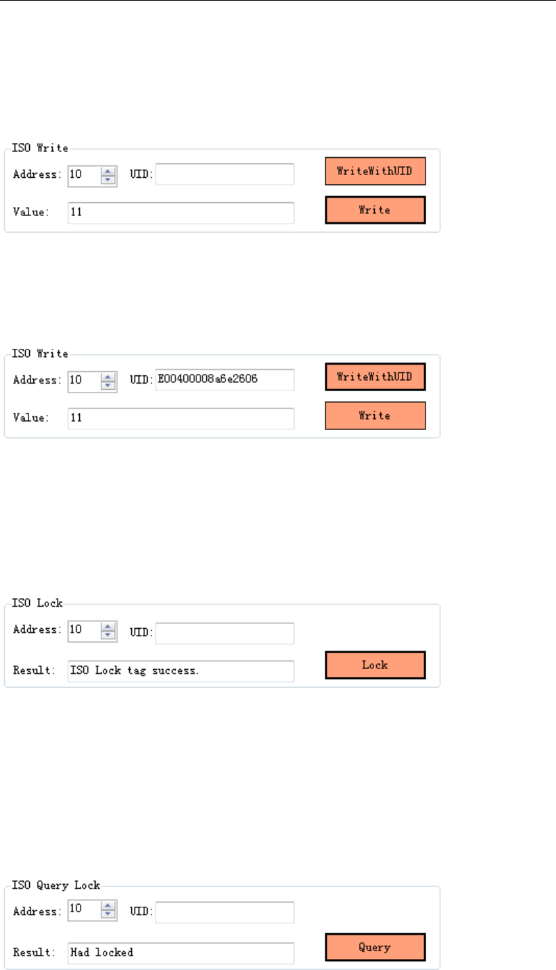
6.2.4 Single tag writing and write with UID
1、Single Tag operation interface,choose the data address you want to write in
the ISO Write menu item,click“Write”button to write data;
2、When operate writing data with UID,except for inputting the single byte data
that needs to write,it also needs to put the UID number of tag,choose the
start address that want to write,click“Write With UID”button to write data;
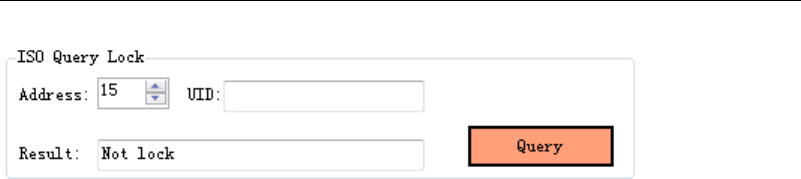
6.2.5 Single tag data lock
1、Single Tag operation interface,choose the data address you want to lock in
the ISO Lock menu item,click“Lock”button to lock data,if return “ISO Lock tag
success” in “Result”column,it means lock successfully:
2、It is unable to rewrite data in the address that is successfully locked;
6.2.6 Single tag lock and query
Single Tag operation interface,choose the data address you want to query in
the ISO Query Lock menu item,click “Query”button to lock and query,it will
return query result in “Result” column,like“Had locked”and“Not lock”;
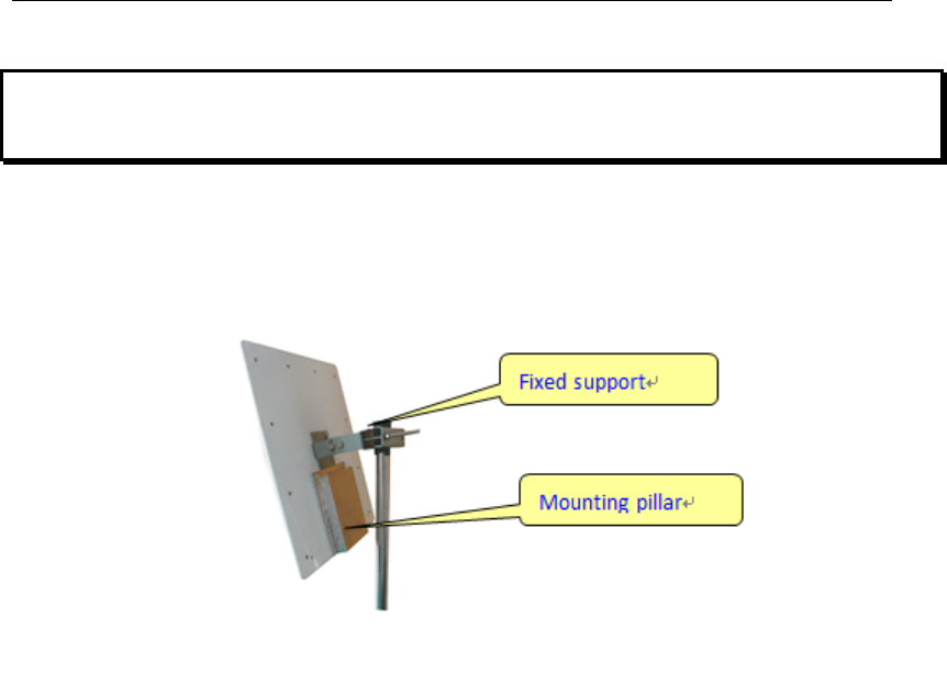
7 Reader struction and installation sketch map
1、 MR6111E、MR6121E integrated reader installation sketch map:

8 Secondary development
User can make secondary development for reader application software if
needing.
We provide SDK,which supports VC++、C#、JAVA and so on,the use of
SDK,please refer to《MR6100 serial reader SDK instruction》。

9 Common faults and exclusion methods
Failure Description Simple exclusion methods
Unable to start reader ■make sure the power adapter indicator light is on
■make sure the reader power interface is connected well
Unable to connect
reader
■make sure the reader IP address is correct
■make sure the network environment is good
Reader is unable to
identify tag
■make sure antenna ports are connected correctly
■make sure antenna power is not to be 0
No sound when
reading tag ■make sure the buzzer is open
Tag with password
operation failed
■make sure that when tag operates with password,the
radiation range of antenna is single tag or small amount
of tags
Invalid tag filter
settings ■make sure the reading mode for reader is multi-tag read
Unable to refresh the
page in the web
configuration
■Clear CGI in the web address or re-enter the IP address
of the reader and refresh
warnings:
This device complies with part 15 of the FCC Rules. Operation is subject to
the following two conditions: (1) This device may not cause harmful
interference, and (2) this device must accept any interference received,
including interference that may cause undesired operation.
Any changes or modifications not expressly approved by the party responsible
for compliance could void the user's authority to operate the equipment.
This equipment complies with FCC radiation exposure limits set forth for an
uncontrolled environment .
This equipment should be installed and operated with minimum distance 20cm
between the radiator& your body.
Note: This equipment has been tested and found to comply with the limits for a
Class B digital device, pursuant to part 15 of the FCC Rules. These limits are
designed to provide reasonable protection against harmful interference in a
residential installation. This equipment generates, uses and can radiate radio
frequency energy and, if not installed and used in accordance with the
instructions, may cause harmful interference to radio communications.
However, there is no guarantee that interference will not occur in a particular

installation. If this equipment does cause harmful interference to radio or
television reception, which can be determined by turning the equipment off and
on, the user is encouraged to try to correct the interference by one or more of
the following measures:
—Reorient or relocate the receiving antenna.
—Increase the separation between the equipment and receiver.
—Connect the equipment into an outlet on a circuit different from that to which
the receiver is connected.