MARS TOHKEN SOLUTION FRU4100Q UHF RFID READER/WRITER MODULE User Manual
MARS TOHKEN SOLUTION CO. LTD. UHF RFID READER/WRITER MODULE Users Manual
Users Manual
User Manual
Version 1.0
FRU-4100Q/FRU-4100QJ
UHF RFID Reader Module

ii
Chapter 1
Chapter
1 .............................................................................................................................. 3
Introducing the FRU-4100Q/FRU-4100QJ ............................................................................. 3
UHF RFID Reader Module ....................................................................................................... 3
Package Content .................................................................................................................... 5
Tour of the FRU-4100Q/FRU-4100QJ UHF RFID Reader Module ......................................... 6
Installing the IndyTool ........................................................................................................... 7
Connecting the FRU-4100Q/FRU-4100QJ to a PC ............................................................... 8
Chapter
2 ............................................................................................................................ 12
Introduction .......................................................................................................................... 12
Indy Tool General Usage ...................................................................................................... 12
IndyTool Functions .............................................................................................................. 16
Chapter
3 ............................................................................................................................ 32
Introduction .......................................................................................................................... 32
Tracer Installation .................................................................................................................. 32
Tracer Usage ......................................................................................................................... 33
Known Issues ....................................................................................................................... 58
Federal Communications Commission (FCC) Statements: .................................................. 59
Table of Contents

3
Chapter 1
Introducing the FRU-4100Q/FRU-4100QJ
UHF RFID Reader Module
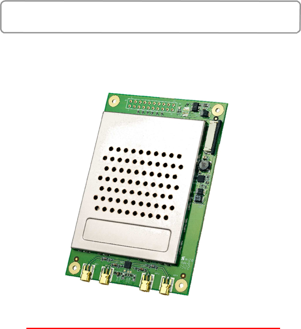
FRU-4100Q/FRU-4100QJ is a high-performance UHF RFID reader module based on
Impinj R2000 chip and compliant with EPC C1 Gen2 / ISO 18000-6C and FCC modular
approval requirements. System Integrators, RFID device makers could use
FRU-4100Q/FRU-4100QJ to develop their own products with the benefits of cost-
efficiency and high-performance.
FRU-4100Q/FRU-4100QJ supports dense reader mode (DRM), anti-collision, and Listen-
Before- Talk (LBT) features. FRU-4100Q/FRU-4100QJ has an operating distance up to 9
meters when its adjustable TX power is set to 30 dBm with a 6 dBi antenna. In addition,
FRU-4100Q/FRU-4100QJ is small and ideal for adding UHF RFID read/write capabilities to
a wide range of products and solutions such as handheld PDA, label printers, stationary
readers, or any other device for UHF RFID applications. FRU-4100Q/FRU-4100QJ uses
Serial and USB interfaces to connect to an external processor board or PC host.
Features
‧
Support for EPC C1 Gen2 / ISO 18000-6C tag protocol with anti-collision, DRM and
‧
Listen-Before-Talk features
‧
Adjustable transmit output level control from 5 dBm to 30 dBm in 1 dB step
‧
Maximum tag read rate of over 100 tags per second
‧
Maximum tag read distance of over 27 feet (9 m) with 6 dBi antenna
Hardware Overview

4
Specifications
Protocol
RFID EPCglobal Gen 2 (ISO 18000-6C), DRM
Architecture
RFID ASIC IMPINJ R2000
Power
Voltage 5V VDC
Current Consumption Scan Mode : 1.5 A (Max),
Idle Modes : 0.33 A (Typical)
Interface
Connector 20-pin (ZIF FPC 0.5mm connector )
UART Baud rates: 9,600 to 115,200 bps, Logic levels: 3.3 / 5 V
USB USB 2.0 Full Speed (12 Mbps)
GPIO 4 GPIO pins, Logic levels: 3.3 / 5 V
API Interface Impinj
RF
Antenna Connector Four MMCX antenna connectors supporting 4 mono-
static antennas, with VSWR less than 2:1
Frequency FCC(US)902-928MHz :FRU-4100Q
TELEC(Japan)916.8-920.4MHz:FRU-4100QJ
TX power Adjustable from 5 dBm to 30 dBm @ +/-1 .0 dBm accuracy
Frequency Stability ±20 ppm
Harmonic performance under 65.0dBc
Modulation Depth 90% nominal
Data Encoding FM0 or Miller code
Bit Rate Supports uplink data rates of up to 640 Kbps
Performance
Tag Read Rate Over 400 tags/second
Inventory Reliability Through anti-collision
Tag Read Distance 27 feet (9m) with a 6 dBi antenna (36 dBm EIRP)
Compliance
Regulatory Certification obtained : FCC 47 CFR Ch. 1 Part 15 , TELEC
Environmental Compliance
Temperature Range Operating: -20 to +60 degree C,
Storage: -30 to + 85 degree C
Humidity 10% ~ 85% Non-condensing
Shock & Vibration TBD
Physical
Dimensions 92.5mm ( L ) X 63mm ( W ) x 4.5 mm ( H )
5
Package Content
FRU-4100Q/FRU-4100QJ UHF RFID Reader Module
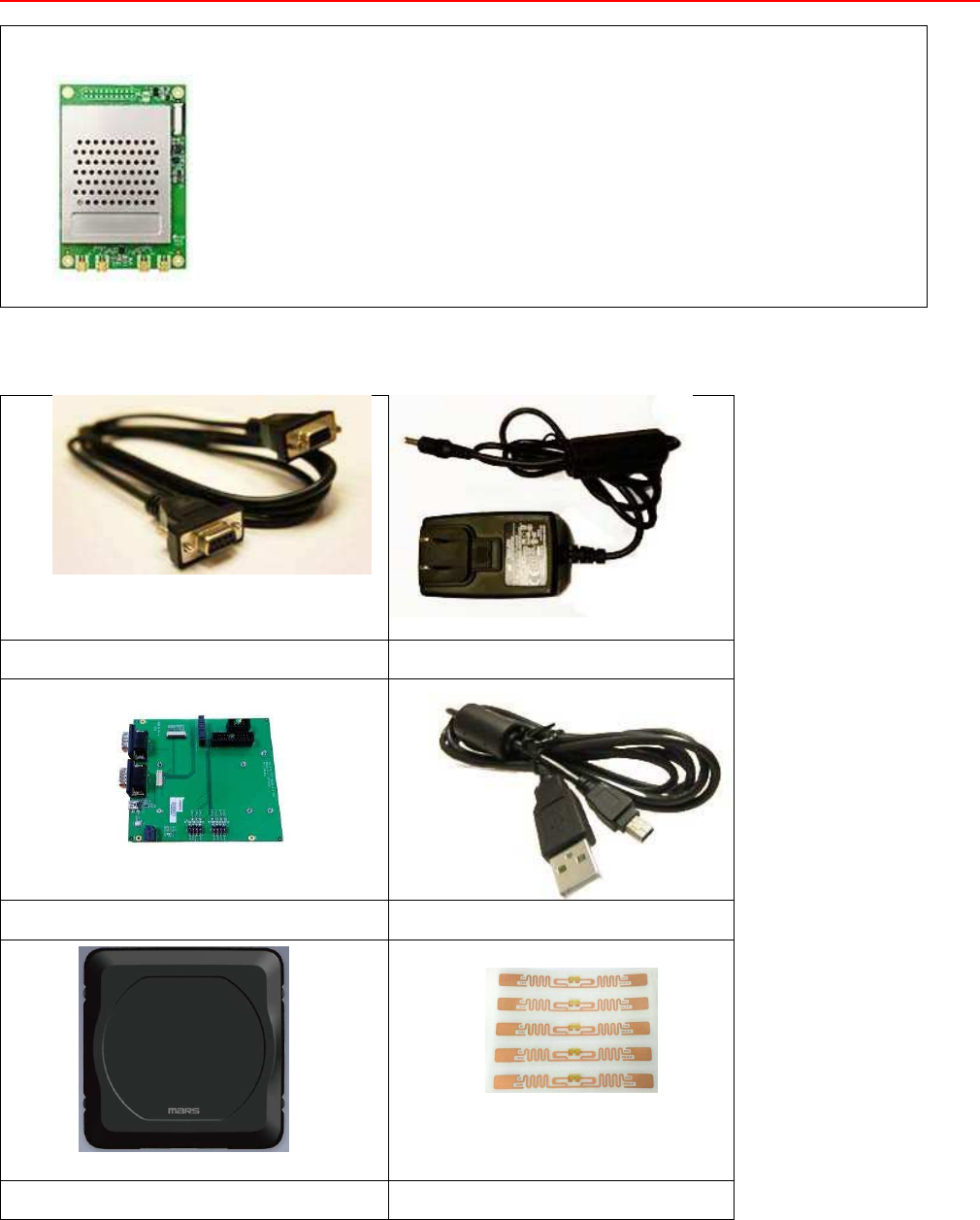
The following equipment is used in the description of this document.
The following devices are sold separately. It is not included in FRU-4100Q/FRU-4100QJ module.
RS232 Cable Power Adaptor
Interface board USB Cable
Antenna RFID Tag
6
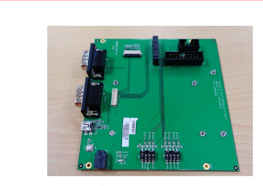
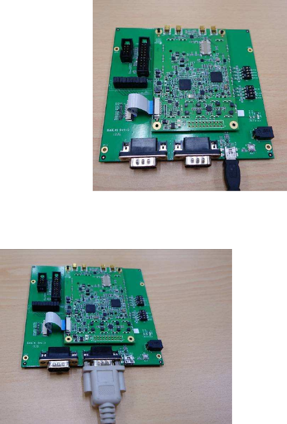
Tour of the FRU-4100Q/FRU-4100QJ UHF
RFID Reader Module
This section describes the main components and features of the
interface board(selling separately; not included inFRU-4100Q/FRU-
4100QJ).
Debug Port
UART Port
Mini USB Port
Power Inlet

7
Installing the IndyTool
First of all, install the IndyTool before connecting the interface board to a PC. It is possible for
multiple versions of IndyTool to co-exist on a single system, so long as a unique install path
is used for each, such as the default installation directory.
Installation Procedure
1.
Double click the IndyTool installer file, IndyTool v2.4.2.msi, to launch the installation wizard.
2.
When prompted, designate the desired installation directory. The default is:
[Program Files]\IMPINJ\IndyTool v2.4.2
3.
Installation includes the C++ runtime libraries and adds a desktop shortcut to the
IndyTool application.
4.
To Start the IndyTool application:
a.
Double click the desktop shortcut, or
b.
Use the Start Menu. For example, if installed to the default directory:
Click Start, select All Programs, IMPINJ, Impinj IndyTool v2.4.2, and click IndyTool.
c.
Open the IndyTool installation folder and double click IndyTool.exe.
8
Connecting the FRU-4100Q/FRU-4100QJ to a PC
Before operating the Indy tool software for development of the RFID device,
follow the steps made below to connect the FRU-4100Q/FRU-4100QJ to a PC.
Interface board, cables, AC adapter, etc. other than FRU-4100Q module are
sold separately.
1.
Install the Indy tool on your PC.
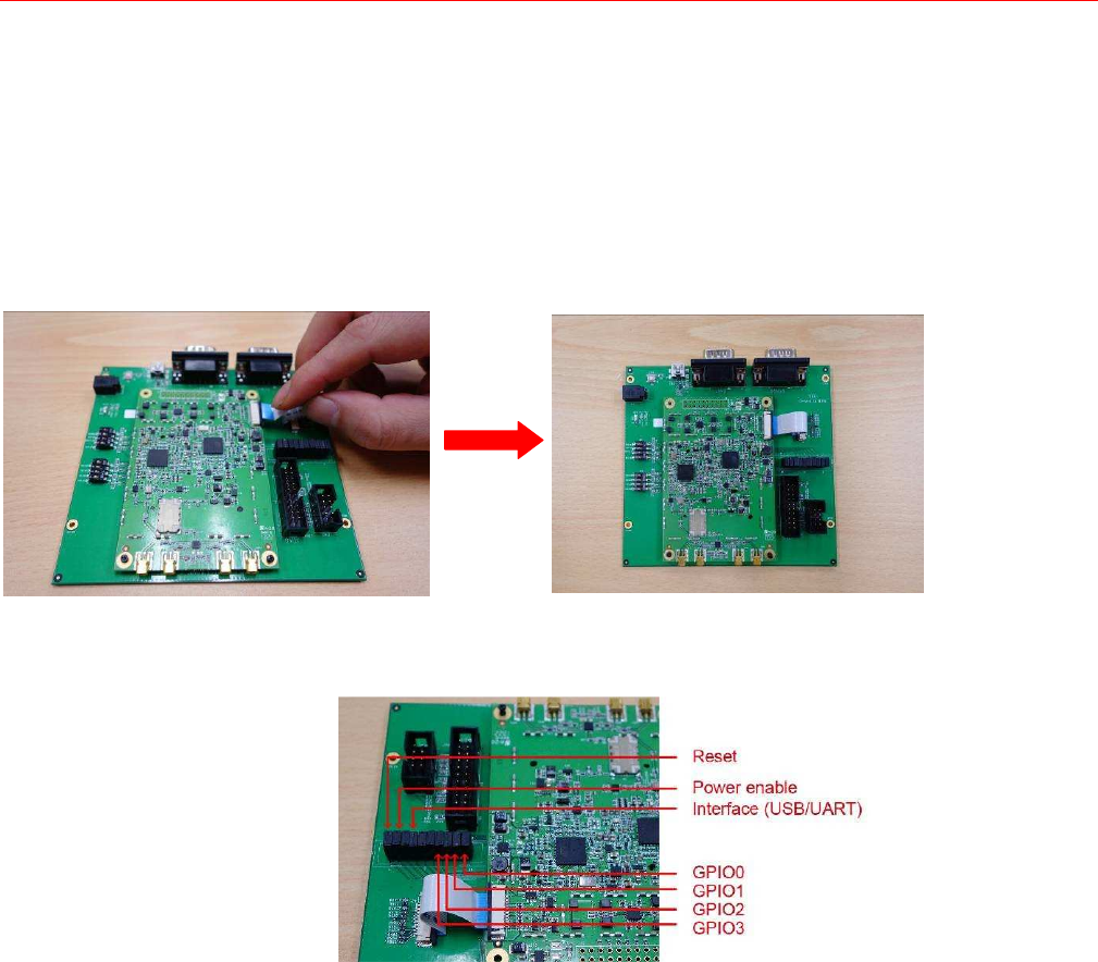
2.
Mount the UHF RFID Module onto the interface board(selling separately;).
Set up the jumper. The jumper settings are defined
below.
9
3.
Connect the interface board to a PC by using a miniUSB cable (default setting) or a RS232
cable, respectively described in options 3a and 3b.
Option a: By using a miniUSB cable
or Option b: By using a RS232
cable
10
4.
Insert the power connector into the power inlet on the interface board, and then
plug the power adapter into an electrical socket.
5.
Connect antennas to FRU-4100Q/
FRU-4100QJ UHF RFID Reader Module. You can
connect at most 4 antennae at the same time.
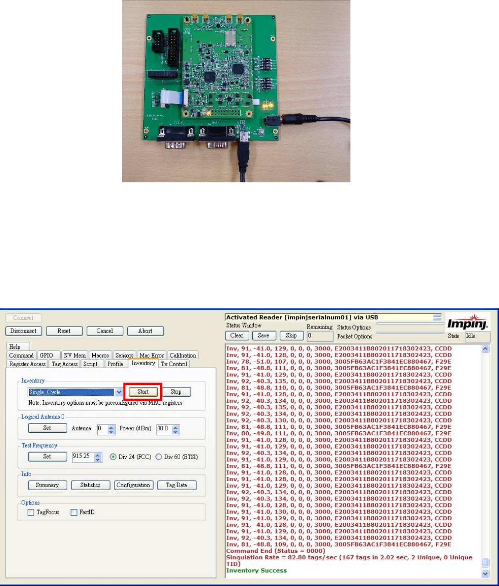
6.
Open the IndyTool. Click Start to scan RFID tags by using the FRU-4100Q/FRU-
4100QJ
UHF RFID Reader module.
11
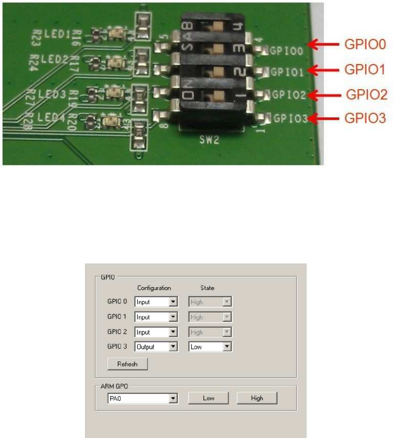
Note: The GPIO settings can be turned on optionally by hardware or software, as
illustrated below.
By hardware, push the GPIO switches to the left.
By software, use the IndyTool to turn on the GPIO settings. The General purpose GPIO can be
configured as Input or Ouptut and the corresponding state is also reflected. The Refresh
button can be used to update the states of the GPIOs configured as input. The greyed state
boxes reflect the Input State. When configured as GPOs the state becomes user
selectable.
The ARM GPOs can be set Low and High via the ARM GPO control box.

12
Chapter 2
Introduction
Overview
The IndyTool is a .Net-based graphical user interface (GUI) tool that uses the Indy
®
RFID
Host Library API to exercise the functionality of the reader platform, a platform that is based
on the Indy chip and firmware.
The IndyTool is dynamically linked to the Indy RFID Host Library. Therefore, there is no need
to install the interface library separately. However, the USB / UART host driver must be
installed prior to using IndyTool.
IndyTool is supported on Windows XP only.
The goal of this document is to explain the operation of the tool. This document does not
explain the underlying RFID functionality that it is controlling via the Indy RFID Host
Library API.
Indy Tool General
Usage
General Guidelines
IndyTool will not modify the reader state without user intervention. The state of the
reader is
only affected when the user executes a function within the application.
Multiple instances of IndyTool can be opened concurrently, however only one reader
in one
instance can be connected at any one time.
All user input fields indicate the input type. The label (d) indicates a decimal input. The
label
(h) indicates a hexadecimal input is expected, and if any other characters are
inputted they will be corrected by the application. Unless otherwise specified all the
input fields in the GUI that are marked (h) do not require the 0x prefix.
All user commands are logged in the Status Window and will show continuous
progress or
show single command execution depending on the status options.
If a reader is disconnected or reset without using IndyTool, the application will show
the last known state of the reader and on the next command attempt, the status will
indicate the connection error. To recover, select disconnect, re-enumerate if
necessary, and connect back to the reader.
IndyTool for Configuration and Development
13
IndyTool can be connected and disconnected to and from a reader at any time.
This will
allow for a user to configure the reader, disconnect and subsequently
run any other application to run the reader.
The target usage for IndyTool is for Engineering Development. The scope of this
document
is to describe the functions in IndyTool and is not meant to describe the
MAC firmware fundamentals, which are a prerequisite to utilizing the system as a
whole.
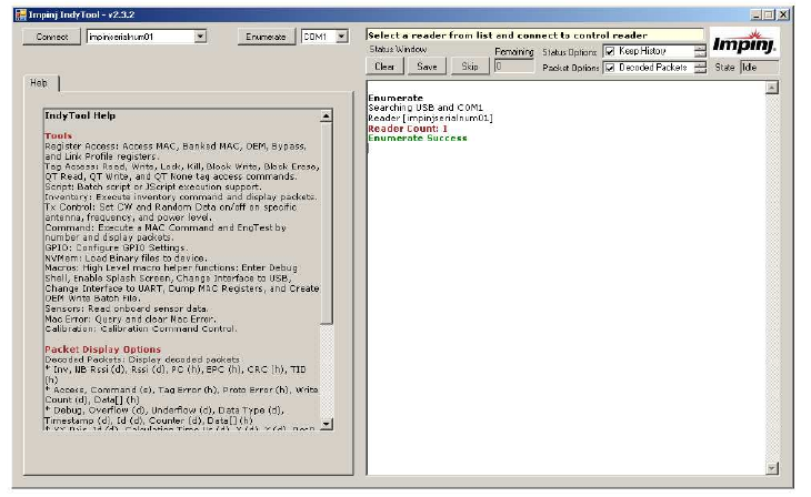
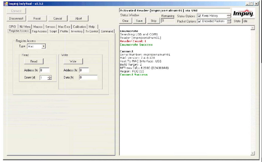
IndyTool Main Window
The following figure shows the main application window.
Main Application Window
On IndyTool startup, all the readers connected to the system via USB and the indicated COM
port are auto-enumerated. The attached readers are indicated in the status window and a
pull down list is populated from which to select.
If there are no readers connected to the system, this will be displayed in the status window
and there will no readers in the pull down menu. If there is a library exception when starting
up the application or any other error, this will be indicated in the status window.
Status Window
The status window shows the outcome of a user command. All commands and functions will
generate some form of feedback in this window.
1.
Clear Button – Clears the current contents of the status window.
2.
Save Button – Save the current contents of the status window to a specified file.
3.
Skip Button – Skips all current status messages queued up by the application for display.
Under some high message traffic conditions, the status window will queue up messages
for display because it may not be able to keep up with influx of messages. This button will
flush the current queue and indicate in the status window how many messages were
skipped and show the tail end of the message queue.
4.
Remaining– This is count of queued up status messages waiting to be displayed in
the status window. The Skip button is most useful when this count is very large and
can be useful to flush the messages and see the final status in the queue.
5.
Status Options – Special options for controlling the status window:
a.
Keep History – [Checked] Append all status messages. [Unchecked] Clear
status window upon each command operation.

14
b.
Status Timestamps – [Checked] Show local timestamp on each status
message. [Unchecked] No timestamp.
c.
Read Only – [Checked] Does not allow user to input any text in status window.
[Unchecked] Allows the user to input notes in the status window, which can be
useful when logging data and results.
d.
Large Window Buffer – Increases the size of the window buffer before flushing.
6.
Packet Options – Special options for controlling Indy packet displaying
a.
Decoded Packets – Displays high level decoded packet information.
b.
Raw Packets 8 – Displays raw packet data in bytes.
c.
Raw Packets 32 – Displays raw packet data in 32-bit words.
d.
Packet Timestamps – Displays packet timestamps in milliseconds (when
available in the packet).
Status Timestamps
Decoded Packets
Raw Packets 8
Raw Packets 32
Packet Timestamps
The status window will self flush automatically when the status window buffer is full. The
window will indicate how many times it has self flush at the top of the status window. The
current windows buffer if 2^16 characters which is approximately equivalent ot 1500
singulations of 96- bit EPCs. Use the large window buffer option to increase the windows
buffer to 2^22.
The Help Tab contains the decoded packet descriptions for reference. The following is the
summary of the decoded packet formats:
Inv, NB Rssi (d), Rssi (d), PC (h), EPC (h), CRC (h), TID (h)
Access, Command (s), Tag Error (h), Proto Error (h), Write Count (d), Data[] (h)
Debug, Overflow (d), Underflow (d), Data Type (d), Timestamp (d), Id (d), Counter
(d),
Data[] (h)
XY-Pair, Id (d), Calculation Time Us (d), X (d), Y (d), Res0 (d), Res1 (d), Res2 (d), Res3
(d)
Info Bar
The Info Bar indicates when a reader is connected or when no reader is connected. The Info
Bar will also indicate the type of connection either USB or UART.
Enumerate
The Enumerate Button will execute the reader enumeration process. The application will
scan the USB interface and the selected COM port for valid readers. The enumeration is
<2/18/2010 11:05:49 AM> Inv, 42,
-
78.0, 3000, 11112222CCCCDDDDEEEEFFF
F, 7098
Inv, 42,
-
78.0, 3000, 11112222CCCCDDDDEEEEFFFF, 7098
Inv, 42, -78.0, 3000, 11112222CCCCDDDDEEEEFFFF, 7098
T:0005 V:01 F:02 L:0007 [ 45 6A 0A 00 58 6D 04 01 4A FE 00 00 30 00 AA AA BB BB CC CC DD DD EE EE FF FF 4A 5B ]
Inv, 42,
-
78.0, 3000, 11112
222CCCCDDDDEEEEFFFF, 7098
T:0005 V:01 F:02 L:0007 [ 000A6A45 01046D58 0000FE4A AAAA0030 CCCCBBBB EEEEDDDD 5B4AFFFF ]
[682579] Inv, 42, -78.0, 3000, 11112222CCCCDDDDEEEEFFFF, 7098
15
only performed when the application is started and when the user presses this button. If a
new reader is connected after the application is started, the enumeration process must be
executed to control the reader. The reader list will be repopulated when the enumeration is
complete. If the reader is not in the pull down list, check the cable connections to make sure
the reader is connected correctly. Depending on the situation and nature of readers using
the UART port, if the reader is not responding (in UART mode) it is best to shutdown the
application and restart to re-enumerate the radio.
When changing the COM port to enumerate, the application will need to be restarted (as
indicated in the status window) to apply the settings. The RFIDcomm.cfg is used to
configure the COM port to control, and by default (after installation) it is set to COM1.
Connect
The Connect Button will attempt to make a connection to the reader selected in the pull down
menu. Upon a successful connection, a new set of menus will appear as shown in the
following figure. If the reader is not connected successfully, it will be indicted in the status
window and no menus will appear.
After the reader is connected it is queried for its parameters.
1.
Serial Number
2.
Bootloader Version (if available and active)
3.
Mac Firmware Version and CRC
4.
RF Transceiver Info –R1000, R2000, R500
5.
Host To MAC Interface = USB or COMx
6. Build Target – 1 = R1000, 2 = R2000, 3 = R500
7. Region – 0 = FCC, 1 = ETSI, 2 = JAPAN

16
The Info Bar will be updated with the name of the connected Reader and the activated Host
To MAC interface.
Disconnect and Reset
The Disconnect Button will attempt to disconnect from the connected reader. The menus
will disappear and the unconnected state will be indicated. The Reset Button will attempt to
reset the connected reader and will also make the menus disappear.
Cancel and Abort
The Cancel and Abort Button will issue the respective command to Reader when
executing a MAC Command. The status window will indicate the issuing of the command
and the reader will respond accordingly.
IndyTool Functions
These sections describe the functions found in the visible menus when a reader is
successfully connected.
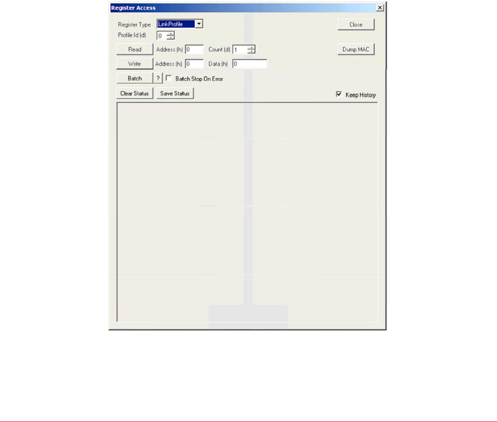
Register Access
The Register Access menu is shown in the following figure.
Connect
Serial Number: impinjserialnum01
MAC Version: 2.2.0.240 (CRC FFFFFFFF)
RFTrans Info: R1000 (000C00B0)
Host To MAC Interface: USB
Build Target: 1
Region: FCC (0)
Connect Success

17
Read Register [Mac]
Read Mac [0000] = 020200F0 (Normal RO)
Write Register [Mac]
Write Mac [0003] = 0000FFFF
Read Register [MacBank]
Read Mac [0702][00] = 00000001 (Banked Sel:0701)
Read Mac Register Bank [0702][00] = 00000001
Read Mac Register Bank [0702][01] = 00000000
Read Mac Register Bank [0702][02] = 00000000
Read Mac Register Bank [0702][03] = 00000000
Read Mac Register Bank [0702][04] = 00000000
Read Mac Register Bank [0702][05] = 00000000
Read Mac Register Bank [0702][06] = 00000000
Read Mac Register Bank [0702][07] = 00000000
Read Mac Register Bank [0702][08] = 00000000
Read Mac Register Bank [0702][09] = 00000000
Read Mac Register Bank [0702][0A] = 00000000
Read Mac Register Bank [0702][0B] = 00000000
There are five Read/Write Register access types:
1.
MAC – Regular MAC Register
a.
[Read] The read address and count are the inputs. The count indicates how
many consecutive addresses to be read. If the application reaches a register
that is not readable, it will stop reading.
b.
[Write] The write address and data are the inputs. This is single write access.
2.
MAC Bank – Banked MAC Register
a.
[Read] The read address and count are the inputs. The count indicates how many
consecutive addresses to be read. If the application reaches a register that is not
readable it will stop reading. A banked read will detect if the register is a banked
register and display the entire banked contents. If it is not a banked register, the
single value is displayed.
b.
[Write] The write address, data and bank number are the inputs. This is a single
write access. If the address is not banked, an error will be displayed.
3.
Bypass – MAC Bypass Register
a.
[Read] The read address and count are the inputs. The count indicates how
many consecutive addresses to be read. If the application reaches a register
that is not readable it will stop reading.
b.
[Write] The write address and data are the inputs. This is single write access.
4.
OEM – OEM Register
a.
[Read] The read address and count are the inputs. The count indicates how
many consecutive addresses to be read. If the application reaches a register
that is not readable, it will stop reading.
b.
[Write] The write address and data are the inputs. This is single write access.
5.
LinkProfile – Link Profile Transceiver Register
a.
[Read] The read address, count, and profile Id are the inputs. The count indicates
how many consecutive addresses to be read. If the application reaches a register
that is not readable, it will stop reading.
b.
[Write] The write address, profile Id, and data are the inputs. This is single write
access. All the results are displayed in the status window.
18
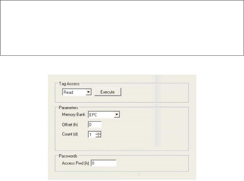
Tag Access
The Tag Access menu is shown in the following figure.
The following are the available Tag Access functions:
1.
Read
2.
Write
3.
Kill
4.
Lock
5.
BlockWrite
6.
BlockErase
7.
QT_Read
8.
QT_Write
9.
QT_None
The following are the general inputs to the Tag Access functions:
1.
Memory Bank – The target for the access operation: EPC, TID, User, or Reserved.
2.
Offset – The offset of the first 16-bit word to access from the target memory bank.
3.
Word Count – The number of 16-bit words to access, starting at Offset.
4.
Values – The 16-bit word values used in access. The values are comma separated
hex
values without the 0x prefix.
5.
Access Password – The access password for the access.
6.
Kill Password – The kill password for performing a kill operation.
7.
Kill Permissions – The kill permissions for performing a kill operation.
8.
QT Controls – The QT controls for performing a QT operation.
Read Mac Register Bank [0702][0C] = 00000000
Read Mac Register Bank [0702][0D] = 00000000
Read Mac Register Bank [0702][0E] = 00000000
Read Mac Register Bank [0702][0F] = 00000000
Write Register [MacBank]
Write Mac Register Bank Fail [INVALID_PARAMETER]
Write Register [LinkProfile]
Write Link Profile [0100][2] = 0000
19
Depending on the function selected, the appropriate inputs fields are displayed and
valid values are required for all fields.
Tag Access
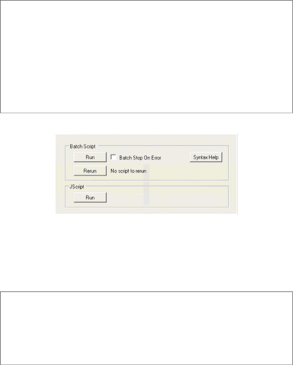
Scripts
The Scripts menu is shown in the following figure.
Batch Script
The Batch Access allows a user to have preconfigured access scripts to quickly configure
the reader for a specific operation. When the Run is pressed a dialog box prompts the user to
select a batch file for execution. The batch files are basic ASCII text with specific commands
to execute in order. There is a Syntax Help button to assist a user with the script format when
operating IndyTool without the manual. The ReRun Button will re-run the last loaded script
file without prompting.
The Batch Script Syntax format legend is as follows:
Tag Access [Read]
Read = Bank:EPC Offset:0002 Count:0001 APwd:00000000
Command Begin (Cmd = 0010)
EPC = 3000CFE900238C87234200000000
Read = Flags:80 TagErr:00 ProtErr:0000 Data:CFE9
Command End (Status = 0000)
Access Count = 1
Tag Read Executed
Tag Access [Write]
Write = Bank:EPC Offset:0002 Value:1234 Count:0001 APwd:00000000
Command Begin (Cmd = 0011)
EPC = 3000CFE900238C87234200000000
Write = Flags:00 TagErr:00 ProtErr:0000 WriteCount: 1
Command End (Status = 0000)
Access Count = 1
Tag Write Executed
Batch Script Help
Legend
* Decimal value or Hex Value (0x_)
** Same as *, but in addition -1 for all banks
# is the comment character
'durationMs' - Indicates time in ms before sending cancel
'inventory' - Executes inventory command and dumps summary upon completion
Commands
script,sleep,*durationMs

20
The following are a list of commands that are supported:
1)
Script Sleep
2)
Mac Command and EngTest Commands (with duration option)
3)
Read/Write of MAC, MAC Bank, Bypass, OEM, and Link Profile Registers
The commands are straightforward and follow the same input requirements as the GUI, but
are in comma separated format. The ability to put comments in the scripts is also available
by using the # symbol. Decimals values are the default input, but if hexadecimal is
preferred then add the prefix 0x to the input.
Note that ‘single_entry’ is provided as an alias to the ‘oem,write’ command for backward
compatibility with previous oem_tool formatted files.
For example, to configure the reader for Fixed Q algorithm with a Q value of 0, the
following commands can be placed in a batch script.
mac,write,0x901,0 # Configure MAC 0x901 with 0
macbank,write,0x903,0,0 # Configure MAC 0x903 Bank 0
with 0
There is a checkbox option called “Batch Stop On Error” that will halt executing a batch script
on any access or syntax error. This may be useful when the use case requires all the
accesses to be successful (for example, when first writing the batch script and checking for
typographical errors). If the checkbox is not checked, the batch will continue to execute even
if an error is detected.
Jscript
The only function available in the JScript menu is to run a JScript. When the button is
pressed, the user is prompted with a dialog for selecting a JScript for execution. If the script
is valid, IndyTool will disconnect from the reader, run the Jscript, and then reconnect back to
the reader for IndyTool control.
mac,command,*id
mac,command,*id,*durationMs
mac,engtest,subcmd,arg0,arg1
mac,engtest,subcmd,arg0,arg1,*durationMs
mac,inventory
mac,inventory,*durationMs
mac,read,*address
mac,read,*address,*count
mac,write,*address,*data
macbank,read,*address,**bank
macbank,read,*address,**bank,*count
macbank,write,*address,*bank,*data
bypass,read,*address
bypass,read,*address,*count
bypass,write,*address,*data
oem,read,*address
oem,read,*address,*count
oem,write,*address,*data
single_entry,*address,*data
linkprofile,read,*address,*id
linkprofile,read,*address,*id,*count
linkprofile,write,*address,*id,*data
21
The JScript feature is legacy feature from the original MACTool which IndyTool is
replacing. The low level MacComDirect Library is used to execute these JScripts.
IndyTool provides a GUI interface to run these scripts. However, when IndyTool is
installed, the MacComDirect is registered in the system so that a JScript can be run
outside the IndyTool application.
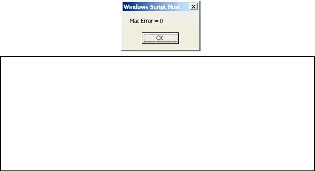
An example JScript is included in the installation directory as a sample. The example script
is called Example.js. The example will query and display the current MAC Error in a pop up
box.
Disconnect
Disconnect Success
JScript Select File
JScript Run Begin
Script: C:\Program Files\IMPINJ\Impinj IndyTool v2.2.0\JScripts\Example.js
JScript Run Success
Connect
Serial Number: impinjserialnum01
MAC Version: 2.2.0.240
RFTrans Info: R1000 (000C00B0)
Host To MAC Interface: USB
Build Target: 1
Region: FCC (0)
Connect Success

22
Get Link
Profile Profile Number: 0
Configuration: 4
Identifier High: 0x00000001
Identifier Low: 0x00000000
Identifier Version: 0x443A8B29
Protocol: 0
R2T Mod Type: 0
Tari: 25000
X: 1
PW: 12500
RTCal: 75000
TRCal: 200000
DR: 2
Miller Number: 0
TRLink Frequency: 40000
Var T2 Delay: 51
Rx Delay: 577
Min To T2 Delay: 75
Tx Prop Delay: 24
RSSI Configuration: 0x00000000
Get Link Profile Success
Profile
The Profile menu is shown in the following figure.
The Profile menu has three profile functions:
1.
Get the profile parameter information – The input is the Profile number.
2.
Set a new active profile – The input is the Profile number.
3.
Get the current active profile – There is no input to this
function. The Get profile function will display all the Gen2 RF profile
information
The Set profile function will execute the Set Current Profile Command.
The Get Current function will read the current and active profile numbers.
Set Link Profile
Profile Number: 0
Command Begin (Cmd = 0019)
Command End (Status = 0000)
Set Link Profile Success
Get Current Link Profile
Current Profile Number: 0
Active Profile Number: 0
Get Current Link Profile Success
23
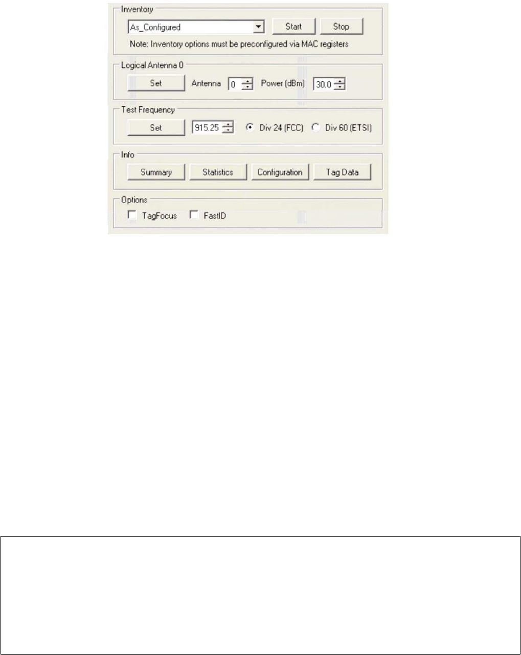
Inventory
The Inventory menu is shown in the following figure.
The Inventory menu has five inventory functions:
1.
As configured – Executes the Inventory command without modifying any Mac Registers
2.
Single Cycle - Executes the Inventory with HST_CYCLES set to 1.
3.
Infinite Cycles - Executes the Inventory with HST_CYCLES set to 0xFFFF.
4.
Test Channel – Executes the Inventory with currently Set Test Frequency. If no
test frequency is set an error will occur. The HST_CYCLES will also be set to
0xFFFF.
5.
Test Channel with Continuous Tx - Executes the Inventory with currently Set Test
Frequency. If no test frequency is set an error will occur. The HST_CYCLES will also be
set to 0xFFFF. The continuous_tx bit in HST_TEST_INVENTORY_CFG will also be set.
The Start and Stop can be used to initiate and terminate the selected inventory option.
Stop is the equivalent to the Cancel Command.
The note indicates that the Inventory must be preconfigured prior to executing the
command (other than the registers that will be explicitly set by IndyTool as described). It is
assumed that the user has preconfigured all the parameters using the Register Access
menu.
After the Inventory command is complete, the basic singulation rate, tag count, duration and
unique count are displayed to the user.
The Logical Antena 0 control box allows the configuration of the ohysical antenna port and
Inventory
Command Begin (Cmd = 000F)
EPC = 3000CFE900238C87234200000000
EPC = 3000CFE900238C87234200000000
…
EPC = 3000CFE900238C87234200000000
EPC = 3000CFE900238C87234200000000
Command End (Status = 0000)
Singulation Rate =34.95 tags/second (70 tags in 2.00 sec, 1 Unique)
Inventory Success

24
power level.
The Test Frequency control box allows the configuration of the test frequency for the
test modes.
The Info control box allows for statistical data to be dumped to the status
window. The Inventory Info has four functions:
1)
Summary – This will provide an overview of statistics of the inventory as a whole
2)
Statistics – This will provide an overview of Gen2 Interface statistics of the inventory
as a whole
Inventory Summary
Status: Completed without errors
Start Time: 1630896 ms (27.2 min)
End Time: 1635611 ms (27.3 min)
Duration: 4715 ms (4.7 sec)
Rate: 57.90 tags/second
Total Tags: 273
Total Unique Tags: 1
Time To See All Once: 20 ms
Inital Inactivity Time: 20 ms
Max Inactivity Time: 47 ms
Final Inactivity Time: 0 ms
Min Rssi: -44.3 dBm
Max Rssi: -42.8 dBm
Inventory Summary Success
Inventory Statistics
Duration: 4.72 sec Query:
286 (60.64 / sec)
RN16 Received: 273 (57.89 / sec)
RN16 Timeout: 4024 (853.27 / sec)
EPC Timeout: 0 (0.00 / sec)
Tag Read: 273 (57.89 / sec)
25
3)
Configuration – This will provide an overview of all the configuration settings for
the inventory.
4)
Tag Data – This will provide an overview of all the individual tag statistics.
5)
Options – This provides an ability to toggle the TagFocus or FastID feature in the
Indy Firmware.
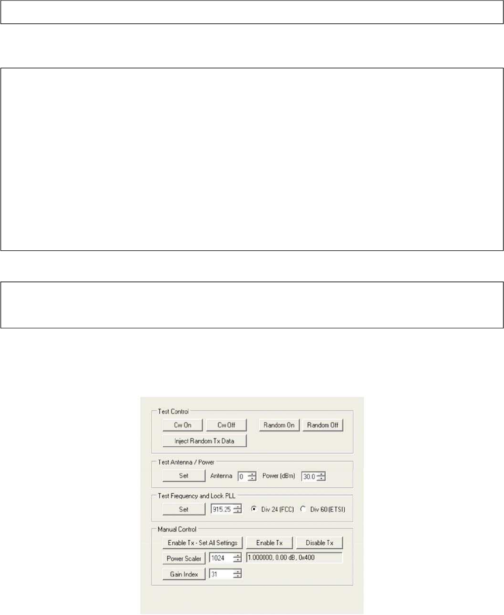
Tx Control
The Tx Control menu is shown in the following figure.
EPC CRC: 0 (0.00 / sec)
Inventory Statistics Success
Inventory Configuration
Algorithm: 1
Stop After N Tags: 0
Issue Select: False (0)
Disable Inventory After Select: False (0)
Query Target: S0 (0)
Query Session: S2 (2)
Query Select Action: ASLINVA_NOTHING (1)
Start Q: 4
Max Q: 15
Min Q: 0
Threshold Multiplier: 4
Query Retry Count: 0
AB Flip: True (1)
Run Until Zero: False (0)
Inventory Configuration Success
Inventory Tag Data
EPC, Count, First Seen (ms), Last Seen (ms), Min Rssi (dBm), Max Rssi (dBm)
3000AAAABBBBCCCCDDDDEEEEFFFF, 273, 20, 4715, -44.3, -42.8
Inventory Tag Data Success
26
The following are the available TX Control functions:
1.
CW On/Off – Controls the CW State.
2.
Random Data On/Off – Controls the Random Data State.
3.
Inject Random Data – Sends Random Tx Data to the Transmit FIFO on the transceiver
chip while in CW operation.
4.
Set Antenna and Power – Sets physical antenna and power level for Test Modes.
5.
Set Freqency – Sets the Test Frequency and locks the PLL for Test Modes.
6.
Manual Tx Control – Functions for Manual Tx Control
a.
Enable Tx (Set All Setings) – Sets Frequency, Power Scaler, Gain Index, and
Enables Tx
b.
Enable Tx – Only enables the Tx. Note other Tx settings must be set in conjunction
to see the transmitter output.
c.
Disable Tx – Disables the Tx.
d.
Power Scaler
–
Sets the power scaler.
e.
Gain Index – Sets the Tx Gain to the gain code in the internal Gross Gain table.
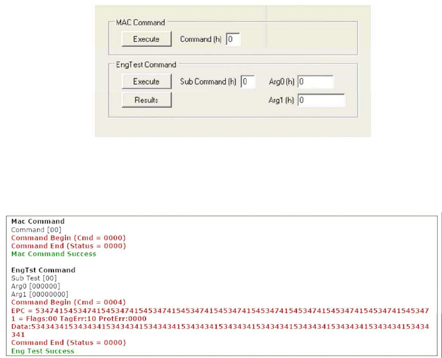
Command
The Command menu is shown in the following figure.
The following are the available Command functions:
1.
MAC Command Execute – The input is the command number.
2.
EngTst Command Execute – This is essentially a regular command operation, but it
allows for easy access to configure the Sub Command and arguments for testing
purposes.
27
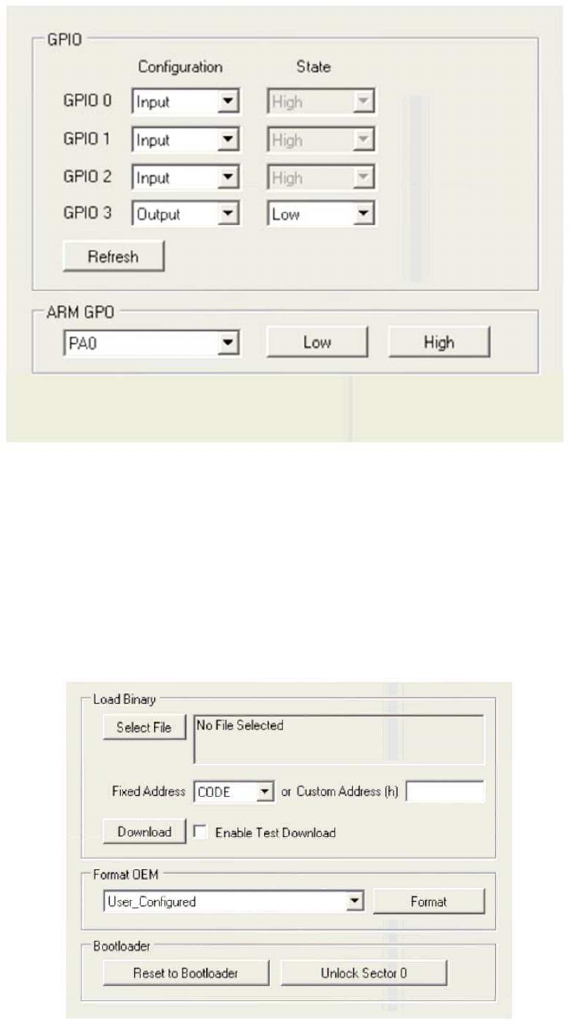
GPIO
The GPIO menu is shown in the following figure.
The General purpose GPIO can be configured as Input or Output and the corresponding state
is also reflected. The Refresh button can be used to update the states of the GPIOs configured
as input. The greyed state boxes reflect the Input State. When configured as GPOs the state
becomes user selectable.
The ARM GPOs can be set Low and High via the ARM GPO control box.
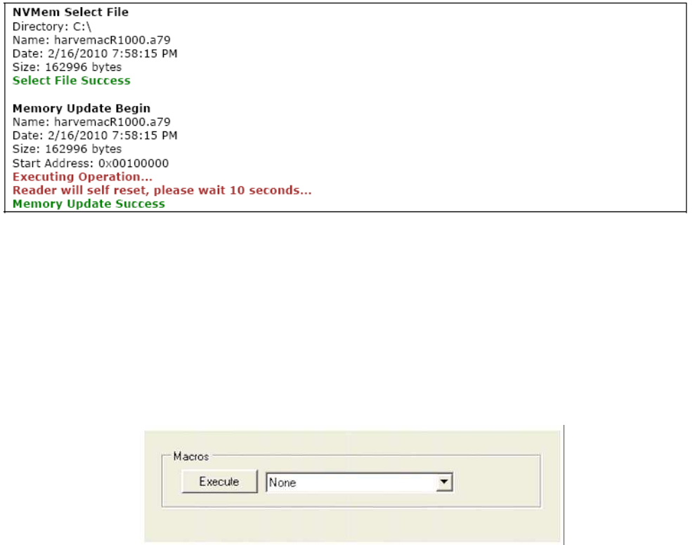
NV Mem
The NV Mem menu is shown in the following figure.
The following are the available Command functions:
1.
Load Binary -
The NV Mem can be used to write to any of the NV memory, but the primary function is
for firmware downloads.
There are three main inputs to this NV Mem update function:
A)
Input File – To select a file, a dialog will prompt the user to select the binary file. Once
selected the file is cached into the IndyTool application and the file properties are
displayed: Name: harvemacR1000.a79 Date: 2/16/2010 7:58:15 PM Size: 162996 bytes
28
B)
Starting NV Memory Address – Either a fixed Address or custom Address can be
selected. For fixed address the options are CODE (0x100000), OEM (0x137C00),
INIT_OEM (0x0013FFF8). A custom address can be entered for special cases. To use
the fixed address, the custom address must be blank.
C)
Test Download – Selects whether to do perform a Test download or an actual download.
When the download button is pressed, the NV Mem sequence commences. If
successful, the reader will reboot itself and IndyTool will ask the user to wait 10 seconds
and then self disconnect from the reader. When the success is indicated, the user can
reconnect to the reader once it is reset.
2.
Format OEM – This is used to initialize the OEM space for a specific platform. The pull
down menu provides the various options for the various supported platforms. The
User_Configured option can always be used, but the appropriate Format OEM
preconditions in the MAC Registers must be configured manually by the user (see the
MAC Register document for further details).
3.
Reset To Bootloader - Allows a user to reset the firmware to the bootloader code.
4.
Unlock Sector 0 – Allows a user to unlock Sector 0 for performing NV Mem updates in
that sector.
Macros
The Macros menu is shown in the following figure.
The following are the available Macros functions:
1.
None – Performs no operation.
2.
Enter Debug Shell – Executes Mac Command to enter into Debug Shell on the
Debug Port.
3.
Enable Splash Screen with 2 second Delay – Configures the OEM to enable splash
screen and sets the Boot Delay to 2 seconds.
4.
Interface to USB – Configures the OEM for the host for USB operation and resets
the reader.
5.
Interface to UART– Configures the OEM for the host for UART operation and resets
the reader.
6.
Dump Mac – Dumps the entire Mac Register Set.
29
7.
Create OEM Batch – Reads the entire OEM space and prompts the user for a file name
to save a Batch script that can be used to write the entire OEM space back to a reader.
Essentially saves the OEM state to a file so that it can be preserved, and the Batch Access
function in the Register Access menu can be used to restore the state.
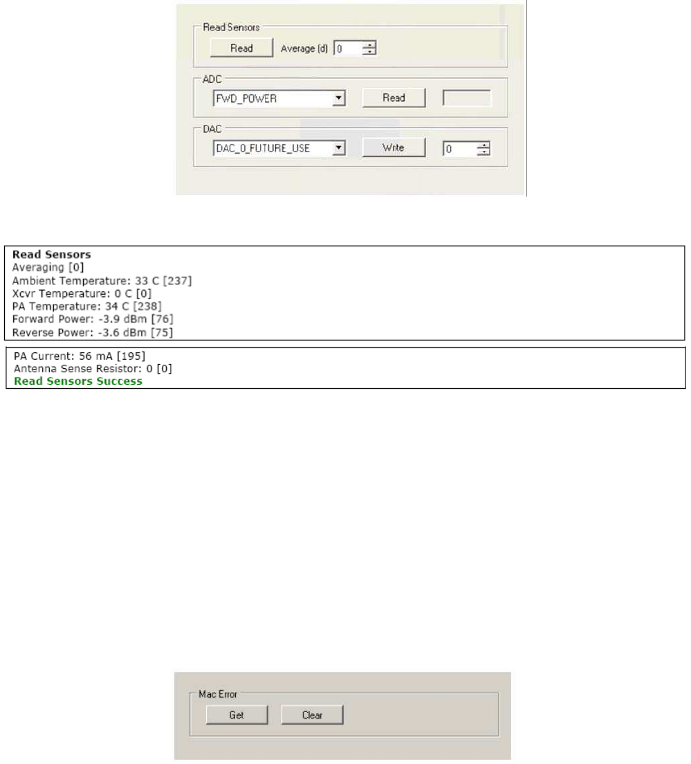
Sensors
The Sensors menu is shown in the following figure.
The following are the available Sensor functions:
1.
Read – The current sensor registers are queried.
2.
ADC – Directly control the ADC
f.
Forward Power
g.
Reverse Power
h.
Ambient Temperature
i.
PA Temperature
j.
Tranceiver Temperature
k.
PA Current
l.
Antenna Sense
3.
DAC – Directly control the DAC
a.
Tranceiver DAC 0 – Future Use
b.
Tranceiver DAC 1 – PA Bias
Mac Error
The Mac Error menu is shown in the following figure.
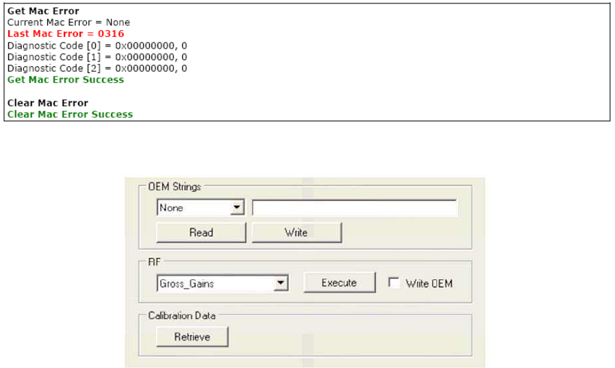
30
The following are the available Mac Error functions:
1.
Get – The Current and Last Mac Error are queried from the reader. Diagnostic codes
are also queried and displayed
2.
Clear – The Clear Mac Command is executed. Note that the Last Mac Error register is
not clearable, only the current Mac Error will be cleared.
Calibration
The Calibration menu is shown in the following figure.
The following are the available Calibration functions:
1.
OEM Strings – Read and Write the OEM Strings directly. The available strings
are Manufacturer, Product and Serial.
2.
RF – The following automatic RF calibration procedures can be performed. Also, the
check box for Write to OEM will automatically store the calibration data to the proper OEM
area on successful calibration completion.
a.
Gross Gain Calibration – Requires forward power detector to be calibrated.
b.
DC Offset –Requires forward power detector to be calibrated.
c.
LBT_RSSI_Threshold – Requires a known signal level (typically -74dBm for Japan)
to be injected into the receive port at the test frequency.
d.
PA Bias DAC Value – Does not have any prerequisites.
e.
PA Bias Current Coefficients – Does not have any prerequisites.
3.
Calibration Data – Dumps RF related calibration data from the OEM configuration space
and formats the data into an IndyTool Batch Script for future use. The script that is
generated can be used in the future to configure the same reader with the same calibration
data.
31
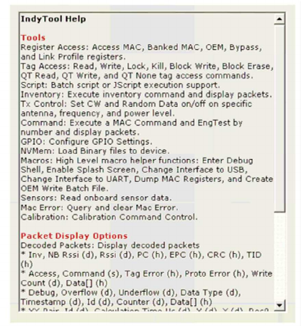
Help
The Help menu is shown in the following figure.
The is no function available in the Help Menu. This menu is for a quick summary of all the
other available functions in other menus.
The Tools section describes all the functions in the specific tabs. The Packet Display
Options section describes the various packet formats and the options related to displaying
packets.
The Status Display Options section describes options related to the Status Display Window.

32
Chapter 3
Introduction
The Tracer application is a .NET-based graphical user interface (GUI) tool that uses the
Indy RFID Host Library API to exercise the functionality of the reader platform, a platform
that is based on the Indy R1000 and R2000 chip, and Indy R1000 and R2000 firmware
respectively.
Tracer is dynamically linked to the Indy RFID Host Library. Therefore, there is no need to
install the interface library separately. However, the USB / UART host driver must be installed
prior to using Tracer.
Tracer is supported on Windows XP only.
The goal of this document is to explain the operation of the tool. This document does
not explain the underlying RFID functionality that it is controlling via the Indy RFID Host
Library API.
Tracer
Installation
Installation Requirements
Tracer requires Microsoft Windows XP Professional with Service Pack 1 (or later). Tracer
also relies on release 2.0 of the Microsoft .Net Framework. The Tracer setup program
checks to ensure that the correct version of the .Net Framework is installed. If the correct
version is not installed, the Tracer setup program offers to install it. The user may also
download and install a copy of the .Net Framework from the Microsoft Windows Update Site
(http://update.microsoft.com/) or the Microsoft Download Center
(http://www.microsoft.com/downloads/).
To communicate with the reader, the current version of the USB / UART host driver must be
installed. See the Indy SDK Getting Started Guide for additional information.
To take advantage of the data import/export feature, Microsoft Excel 2003 is required.
Installation
It is possible for multiple versions of Tracer to co-exist on a single system, so long as a
unique install path is used for each, such as the default installation directory.
Installation Procedure
To install the Tracer tool:
1.
Double click the Tracer installer file, Tracer v2.4.
2.
2.msi, to launch the installation wizard.
3.
When prompted, designate the desired installation directory. The default is [Program
Indy Tracer for Demonstration
33
Files]\IMPINJ\Tracer v2.4.2\. 3. Installation includes the C++ runtime libraries and
adds a desktop shortcut to the Tracer application.
4.
To Start the Tracer application:
Double click the desktop shortcut, or Use the Start Menu. For example, if installed to
the default directory:
Click Start, Select All Programs, IMPINJ, Impinj Tracer v2.4.2, Click Tracer.
Open the Tracer installation folder and double click Tracer.exe.
Removal Procedure
To uninstall the Tracer tool:
1.
Click Start, Select All Programs, IMPINJ, Impinj Tracer v2.4.2, Click Uninstall Tracer.
2.
When prompted to uninstall this product, click Yes.
Alternatively:
1.
Open the Control Panel and select Add or Remove Programs.
2.
Select the entry for the Tracer version to uninstall and click Change/Remove.
3.
When prompted to remove this product, click Yes.
Configuring for UART Operation
In the installation directory there is a file called RFIDcomm.cfg. This file contains the COM
Port number if UART operation is desired. The Tracer program will need to be restarted if
this files is changed. With UART operation, only a single reader can be controlled.
Tracer Usage
This section describes the features of the Tracer Application.
Tracer has been adapted with reader platform differences in mind. Consequently, Tracer
version
2.2.0 supports both the Indy R1000-based and R2000-based reader, hereafter referred to as
the reader.
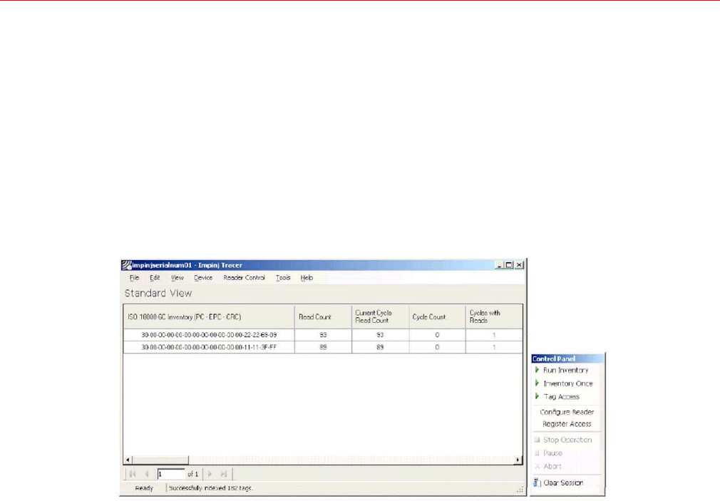
Tracer Appearance
The Tracer consists of a main display window and a floating control panel window. See
figure below.
The main window contains a menu and a main display area used to show different views
of
the data received from the reader.
The floating control panel is used to start, stop, and pause inventory rounds, and to
perform
other reader actions.
Tracer User Interface Main Window (left) and Control Panel
(right)
34
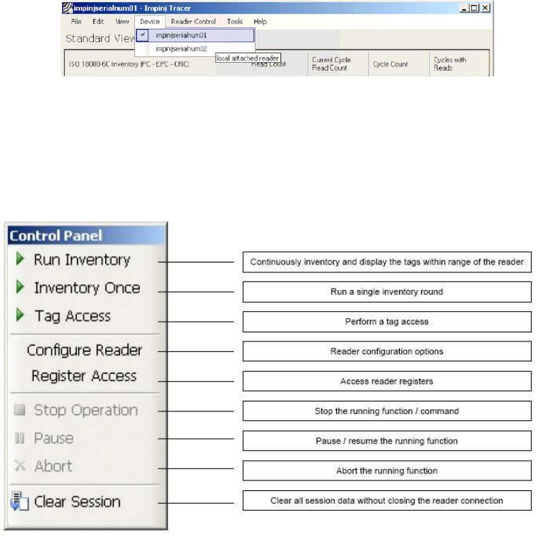
Selecting a Device and a Mode
Selecting a Device
When the Tracer application starts, it attempts to open all attached readers. Each attached
reader is listed separately in the Device menu. If no readers are found, the application
displays a warning and the Device menu is empty.
The reader that is found first is automatically selected as the active device. The name of the
active reader device is always displayed on the window caption. To change the active
reader, make a selection from the Device menu as shown in the figure below.
Controlling a
Device
The Device Menu
After making a selection from the Device menu, you can control the active reader from the
Reader Control menu or from the floating Control Panel. The figure below shows the
Control Panel buttons and describes the actions they perform.
Reader Control
Panel
35
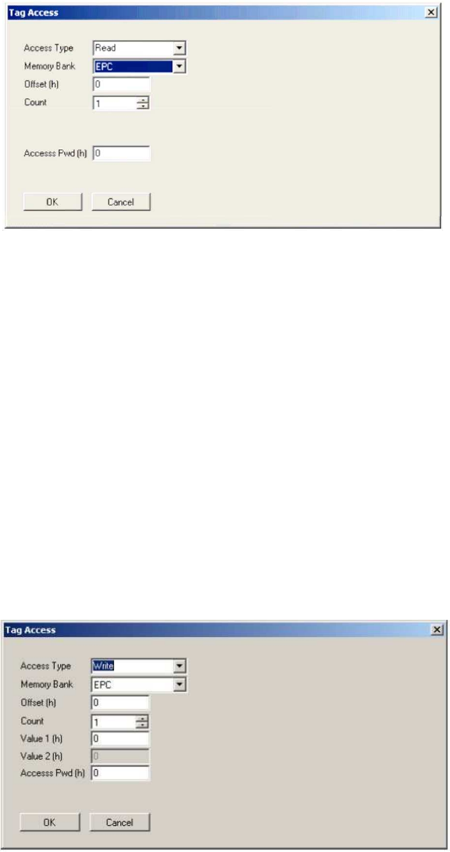
Tag Access
Selecting the Tag Access option presents the user with the configuration dialog shown in the
figure below.
Tag Access dialog box, Access Type Read selected
From the Tag Access dialog box, the user can perform many different access operations
against tags as follows.
Access Type Read
Selecting the Read Access Type option displays the configuration dialog shown in the
figure above.
From this dialog, the user can perform a read operation against tags and can provide
the following configurable parameters:
‹
Memory Bank—the target for the read operation, has selectable values of either
the EPC, TID, User, or Reserved memory bank
‹
Offset—the offset in hexadecimal of the first 16-bit word to read from the target
memory bank
‹
Count—the number of 16-bit words to read, starting at Offset
‹
Access Pwd—the previously applied access password for the target tag, or no
entry for tags with no access permissions
Output from read operations is directed to the primary application window.
Access Type Write
Selecting the Write Access Type option displays the configuration dialog shown in the
figure below.
Tag Access dialog box, Access Type Write selected
36
From this dialog, the user can perform a write operation against tags and can
provide the following configurable parameters:
‹
Memory Bank—the target for the write operation, has selectable values of
either
the EPC, TID, User, or Reserved memory bank
‹
Offset—the offset in hexadecimal of the first 16-bit word to write from the
target
memory bank
‹
Count—the number of 16-bit words to read, starting at Offset
‹
Value 1—the hexadecimal value of the 16-bit word to write at Offset
‹
Value 2—the hexadecimal value of the 16-bit word to write at Offset+1,
applicable
if Count is 2
‹
Access Pwd—the previously applied access password for the target tag, or
no
entry for tags with no access permissions.
Output from write operations is directed to the primary application window.
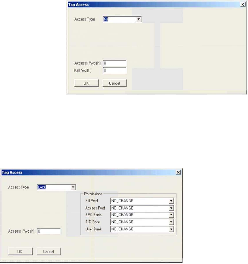
Access Type Kill
The kill operation allows the user to render any tag with a matching access and kill
password as permanently non-functional. Selecting the Kill Access Type option displays
the configuration dialog shown in the figure below.
Tag Access dialog box, Access Type Kill selected
Note: Tags with a value of zero for their password are not expected to respond to the
kill command.
Access Type Lock
The lock operation allows the user to specify the desired exposure of tag kill and
access password permissions. It also allows the user to specify write permission and condition
levels for the EPC, TID, and User memory banks. Selecting the Lock Access Type option
displays the dialog box shown in the figure below.
Tag Access dialog box,
Access Type Lock
selected
37
Note that all permissions are set in a single operation. In many circumstances, it may
be desirable to leave one or more of the target passwords or permissions in an unmodified
state. To do this, select the NO_CHANGE option for those targets.
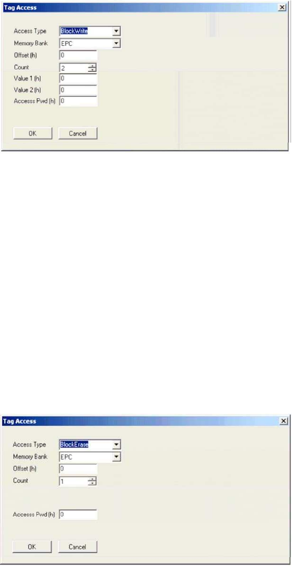
Access Type BlockWrite
Selecting the BlockWrite Access Type option displays the configuration dialog shown in
the figure below.
Tag Access dialog box, Access Type BlockWrite selected
From this dialog, the user can perform a block write operation against tags and
can provide the following configurable parameters:
‹
Memory Bank—the target for the read operation, has selectable values of
either
the EPC, TID, User, or Reserved memory bank
‹
Offset—the offset in hexadecimal of the first 16-bit word to read from the target
memory
bank
‹
Count—the number of 16-bit words to read, starting at Offset
‹
Value 1—the hexadecimal value of the 16-bit word to write at Offset
‹
Value 2—the hexadecimal value of the 16-bit word to write at Offset+1,
applicable
if Count is 2.
‹
Access Pwd—the previously applied access password for the target tag, or no
entry for tags with no access permissions.
Output from block write operations is directed to the primary application window.
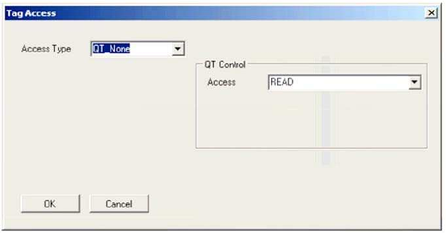
Access Type BlockErase
Selecting the BlockErase Access Type option displays the configuration dialog shown
in the figure below.
Tag Access dialog box, Access Type BlockErase selected
38
From this dialog, the user can perform a read operation against tags and can
provide the following configurable parameters:
‹
Memory Bank—the target for the read operation, has selectable values of
either
the EPC, TID, User, or Reserved memory bank
‹
Offset—the offset in hexadecimal of the first 16-bit word to erase in the target
memory bank
‹
Count—the number of 16-bit words to erase, starting at Offset
‹
Access Pwd—the previously applied access password for the target tag, or
no
entry for tags with no access permissions.
Output from block erase operations is directed to the primary application window.
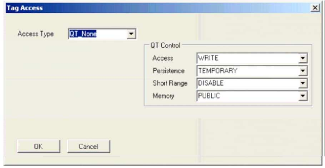
Access Type QT_None
Selecting the QT_None Access Type option displays the configuration dialog shown in
the figure below.
Tag Access dialog box, Access Type QT_None selected and QT Control Access READ option
selected
From this dialog, the user can perform a QT control data read or write operation
against
tags.
The figure above illustrates the QT Control Access READ option, for which no
additional
parameters are required.
Selecting the QT Control Access WRITE option displays additional options in the
configuration dialog shown in the figure below.
39
Tag Access dialog box, Access Type QT_None selected and QT Control Access WRITE option selected
40
Refer to Monza4_Tag_Chip_Datasheet for an explanation of these QT
related parameters. Output from QT operations is directed to the primary
application window.
Access Type QT_Read
Selecting the QT_Read Access Type option displays the configuration dialog shown in
the figure below.
Tag Access dialog box, Access Type QT_Read selected
From this dialog, the user can perform a QT control data read or write operation
followed immediately by a read operation against tags.
The configurable parameters for the QT control data read or write operation are
identical to those in section titling Access Type QT_None.
The configurable parameters for the QT read operation are identical to those in
section titling Access Type Read. Output from QT read operations is directed to the primary
application window.
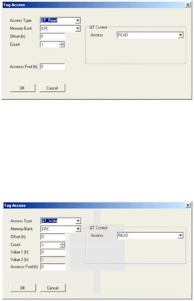
Access Type QT_Write
Selecting the QT_Write Access Type option displays the configuration dialog shown in
the figure below.
Tag Access dialog box, Access Type QT_Write selected
From this dialog, the user can perform a QT control data read or write operation
followed immediately by a write operation against tags.
The configurable parameters for the QT control data read or write operation are identical to
those in section titling Access Type QT_None..
41
The configurable parameters for the QT write operation are identical to those in section
3.3.1.2. Output from QT write operations is directed to the primary application window.
RFID Data Views
Overview
The Tracer provides several views that allow users to examine RFID data from
different perspectives. Use the View menu (on the main window) to select different
views.
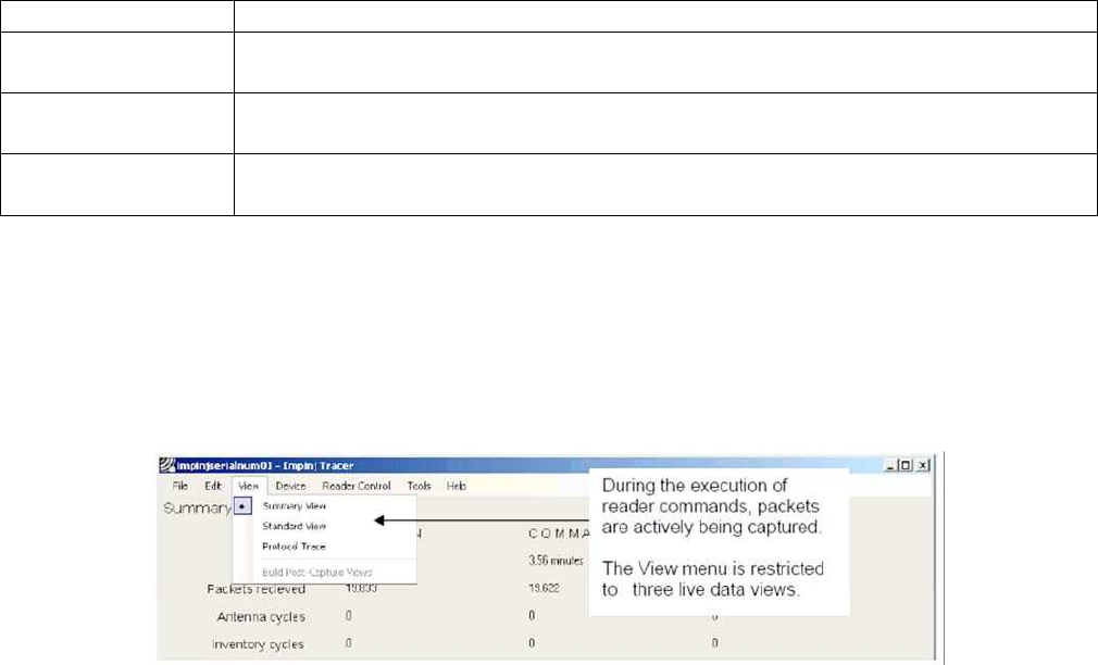
Tracer provides two types of data views:
Live data views, which are captured in real-time from the reader
Post-capture views, which are generated after an operation is completed
The live data views display data as the packets arrive from the reader. The application
applies minimal processing to this live data. The following table describes the three live data
views that are available.
Live Data
Views
View Name
Contents
Summary View
Overview statistics about the current session, currently executing
command and reporting time slice.
Standard View
A list of unique tag singulations (tag id inventoried) in the session and a
count of the number of times the id was read (inventoried).
Protocol Trace
A graphical view of the packet data for the current (active) command
broken out by the packet fields.
Note that while a reader is actively executing a command, such as Inventory, only live data
views are available. Even if a user has selected a post-capture view, the view is
automatically switched to a live data view when a command is issued to the reader.
While the command is running, users can switch between any of the three live views
(Summary,
Standard and Protocol Trace). However, the user interface prevents users from switching
to any of the post-capture views. See the figure below.
View Menu Options – During Reader Command Execution
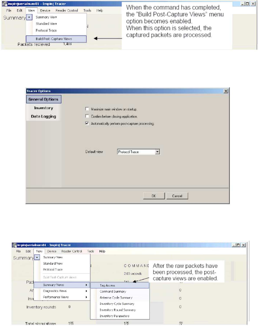
Performing Post-Capture Processing
After one or more reader functions has completed, Tracer must perform the post-
capture processing to create the post-capture views. The post-capture processing builds
an index of the captured data which provides the data for the post-capture views.
You can perform the post processing by initiating it yourself or by configuring the application
to invoke it automatically. The procedure for each approach is described below:
To initiate the post processing (i.e., to build the indexed data file), select Build Post-
Capture
Views as shown in the figure below. This option is enabled after the reader
functions have completed.
42
View Menu Options - Build Post-Capture Views
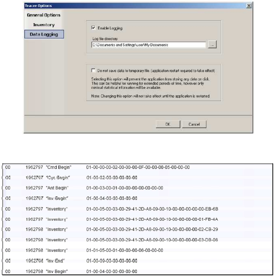
To configure the application to automatically invoke the post-capture processing:
1.
From the Tools menu, select Tracer Options. The Tracer Option dialog box displays.
2.
Select Automatically perform post-capture processing as shown in the figure below.
Automatically Perform Post-Capture
Processing
When the post-capture processing completes, all views become available from the View menu,
as shown in the figure below.
View Menu Options - Post-capture Views
Except for the Reader Protocol view, all post-capture views are divided into three groups
under the submenus:
Packet Views
Diagnostic Views
Performance Views
The Protocol Trace is the only view that supports the display of both live and post-capture data.
When the reader is active, the Reader Protocol view displays the last one thousand captured
packets for the current command. When the post-capture process completes, the Reader
Protocol view displays all packets for the active session.

43
The following table lists the post-capture packet views that are available:
Post-Capture Packet Views
View Name
Contents
Tag Access
Lists in chronological order all Inventory Response packets received from
the reader. The view includes the Tag ID, time of packet arrival, the
Antenna number, device time, the access type, and the tag data.
Command
Summary Provides summary information about the commands executed by the
reader in the current session. Data items include elapsed time of the
command, execution mode, tag count, unique tag count, and tag read
rate.
Antenna Cycle
Summary Provides summary information about the antenna cycles executed by the
reader in the current session. Data items include the number of antennas
included, the tag count, unique tags, and tag singulation rate.
Inventory Cycle
Summary Provides a summary of all of the inventory cycles included in the current
session (or since the last time the session was cleared). The view
includes the total and unique tag count, logical antenna number, and read
rate.
Inventory Round
Summary Lists data related to each inventory round including the antenna used, tag
count, and elapsed time in milliseconds.
Inventory
Parameters
Lists the parameter used in the session’s inventory roun
ds.
The following table lists the post-capture diagnostic views that are available:
Post-Capture Diagnostic
Views
View Name
Contents
All Packets
(Raw Format)
Lists in chronological order all packets received from the reader.
Invalid Packets
Lists invali
d or unrecognized packets, the raw data, and the parsing error.
Inventory Cycle
Diagnostics
Lists diagnostic information for each inventory cycle.
Note: The extended data format must be selected to obtain this information.
Inventory Round
Diagnostic
List
s the diagnostic information for each inventory round.
Note: The extended data format must be selected to obtain this information.
The following table lists the post-capture performance view that is available:
Post-Capture Performance
View
View Name
Conte
nts
Singulation Rate
Data
Provides data useful for calculating the read rate achieved by the reader.
Exporting Data
The Tracer application allows you to export data to Microsoft Excel 2003. To export
data:
From the File menu, click Export. A dialog box opens from which you can select the
views
you wish to export. You can export one or more views at a time.
The application saves exported files in the user’s temporary directory. After the export
completes, Tracer invokes Microsoft Excel, or the associated application for xml format
worksheets, to open the exported data file. Each view selected for export becomes a
separate sheet in an Excel workbook.
Note: Microsoft Excel allows only the first 65536 rows in each view to be exported. If a session is too big
for Excel, you can always view it in the Tracer application.
44
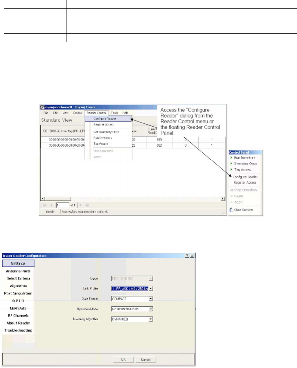
Logging Data
Tracer supports the logging to a text file of all packets received from readers. See figure below
To enable logging:
1.
From the Tools menu, click Tracer Options. This opens the Tracer Options dialog box.
2.
In the Tracer Options dialog box, click the Data Logging tab.
3.
Select the Enable Logging check box.
4.
If desired, specify an alternative directory in which log files should be stored.
Data Logging
The log files created by Tracer are named rfidxxxx.log, where xxxx is a four digit sequence
number. The figure below shows an example of log file content.
Log File Example
45
The log file contains four fields separated by tab characters. These fields are defined in
the following table.
Log File Field Definitions
Field
Contents
Radio Index
A unique serial number for the reader.
Time stamp
Elapsed time in milliseconds from the start of the session.
Symbolic Name
The symbolic name for the packet.
Packet Data
The packet data in hexadec
imal format.
Accessing and Changing Reader Configuration
The Tracer application allows the user to configure many of the settings of the
attached readers.
To access the configuration panel:
From the Reader Control menu, select Configure Reader. Alternatively, from the
Control
Panel, select Configure Reader. See the figure below. This opens the Tracer
Reader Configuration dialog box.
Accessing the Reader Configuration Dialog
The Tracer Reader Configuration dialog contains many function-specific pages, each of
which is listed on the left-hand side selection bar. The current selection is always indicated
by a visual highlight. For example, in the figure below, the Settings page is active.
Reader Configuration Dialog Box
46
The following sections describe each page of the Tracer Reader Configuration dialog box—
starting with the Settings page. Refer to the Indy_Firmware_Datasheet and the
IN_DG_IPJ_Indy_RFID_Host_Library_API_Reference_Manual for a description of the
underlying functionality.
Settings Page
When the Reader Configuration dialog first opens, it displays the Settings page shown in the
figure above. The settings displayed are the current settings on the reader. From this page,
you can view and/or configure the following items:
Operating Region (Read only, set within the reader)
Link Profile • Data Format (Compact, Normal or Extended)
Operational Mode (Continuous Mode or Discontinuous Mode)
Inventory Algorithm (Fixed Q or Dyanmic Q)
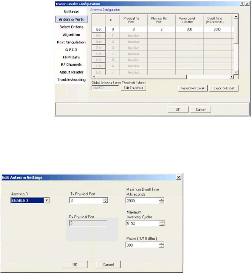
Antenna Configuration Page
From the Antenna Configuration page, you can configure the reader’s 16 logical antenna ports.
As the figure below shows, this page displays the current antenna configuration within a grid.
Antenna
Configuration
The Import and Export buttons allow the antenna data to be manipulated by Microsoft Excel
and then imported back into the reader.
To change the setting for a logical antenna, click its associated Edit button in the first column
of the grid. This displays the dialog box shown in the figure below.
Antenna Logical Settings
47
Configurable parameters for individual antennas are:
Tx Physical Port indicating the physical connector (0 thru 3) to which the logical
antenna is
bound for transmission of data.
Rx Physical Port indicating the physical connector to which the logical antenna is
bound for receipt of data. This value is currently bound and must be equal to the Tx
Physical Port value.
Maximum Dwell Time indicating the maximum number of milliseconds that may be
spent on
the logical antenna during a single cycle.
Maximum Inventory Cycles specifying the maximum number of inventory cycles that
will be
spent on the logical antenna before a switch to the next one available.
Antenna transmission Power in 1/10 dBm increments.
Note: The dwell time and inventory cycles may not both be set to a value of zero. If the user attempts to
perform such an operation, the last of the two fields to be modified will automatically have its value converted
to one (1).
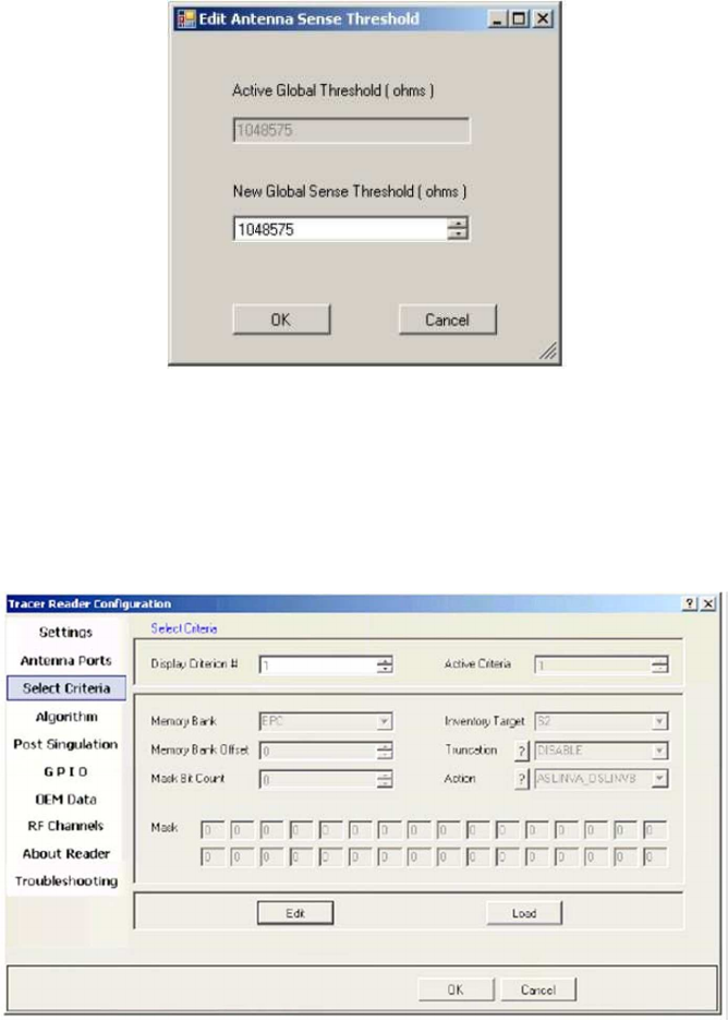
To change the global antenna sense threshold, click on the “Edit Threshold” button. This
will
bring up the dialog box shown in the figure below.
Select Criteria
Page
Antenna Sense Threshold Settings
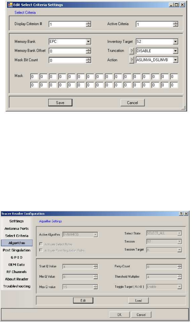
Use the Select Criteria page to view and configure the selection criteria query settings that can
be used for any tag–protocol operations. As shown in the figure below, this page displays the
active selection criteria of the current reader.
Select Criteria View
48
The Display Criterion # spin box allows you to select the criteria currently being viewed. It
has a range of one (1) up to the value displayed under Active Criteria.
The Load button causes the application to perform a direct query to the current reader
and reload the page with the retrieved select criteria settings.
To change the select criteria parameters for the active reader, click the Edit button.
T
his displays the dialog box shown in the figure below.
Select Criteria Edit Dialog
This panel allows configuration of individual select criterion parameters.
Note 1: Only one active select criteria is allowed at this time. Attempts to set the Active Criteria count (in the Edit
dialog) greater than one (1) results in an Invalid Parameter error. This error is generated and displayed when the
Save button is clicked.
Note 2: Truncation is not supported in the Indy firmware at this time. The Truncation parameter should be set to
DISABLE.
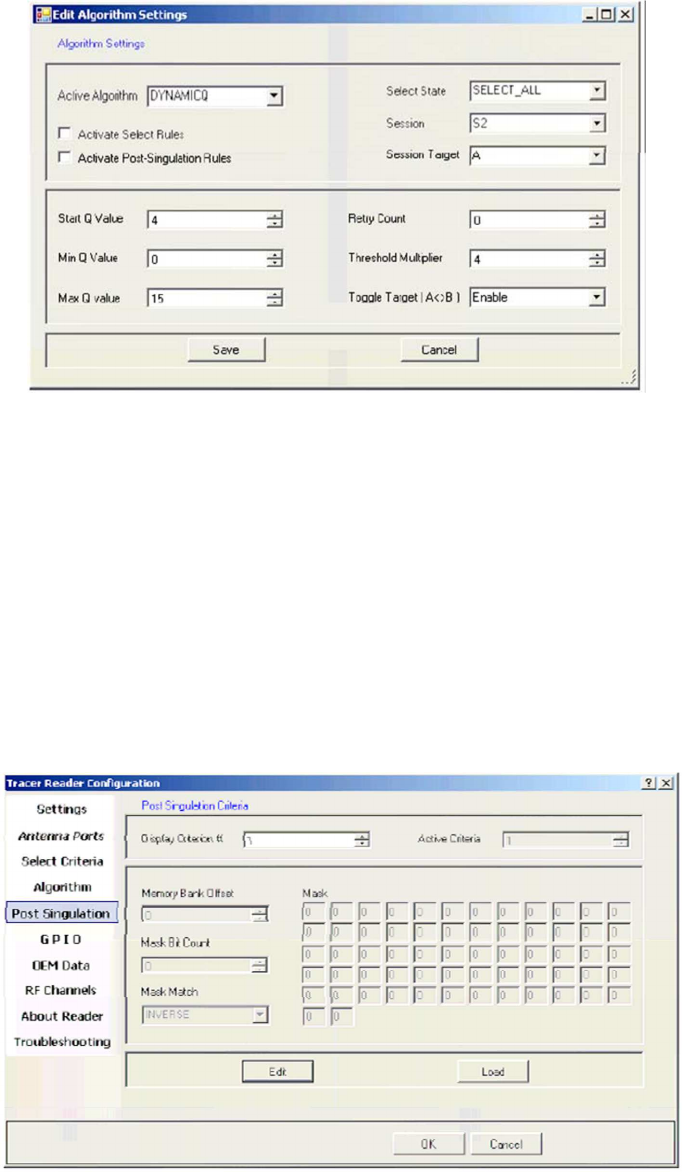
Inventory Algorithm Panel
The Inventory Algorithm panels are used to view and configure the reader’s query settings,
the parameters for the selected singulation algorithm, and whether select and post singulation
filters should be utilized during inventory, read, write and similar operations.
The figure below shows an example of the Inventory Algorithm View panel.
Algorithm Settings View
Page
49
The Load button queries the current reader and refreshes the values displayed on the
Algorithm Settings page.
To modify the algorithm settings for the current reader, click the Edit button. This opens a
dialog box similar to the one shown in the figure below.
Inventory Algorithm Edit Page
In the Active Algorithm dropdown box, you can select between the Fixed Q and Dyanmic Q
algorithm. When you select a new algorithm, the configurable fields displayed in the center
sub-panel change to match those available with the selected algorithm.
The Activate Select Rules and Active Post-Singulation Rules checkboxes control whether the
select and post singulation criteria that have been configured should be utilized during
inventory, read, write, and similar operations.
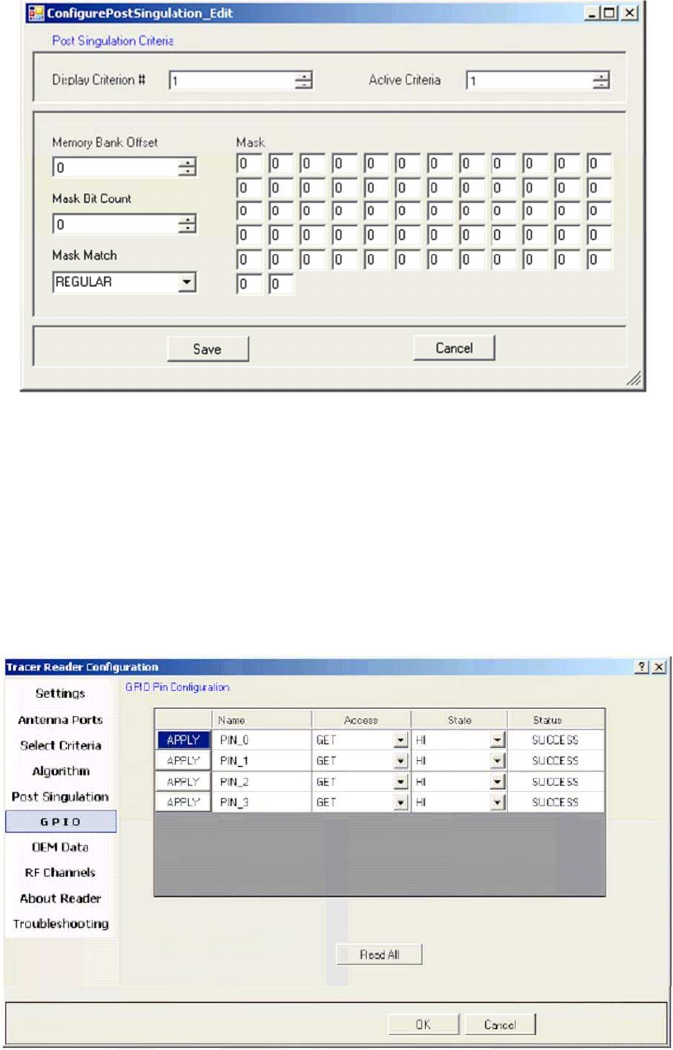
Post Singulation Criteria Page
Use the Post Singulation page to view and configure reader settings that define the manner in
which tags and post singulation are filtered (based on all or part of the tag’s EPC).
The figure below shows an example of the page displayed when the Post Singulation Criteria
option is chosen.
Post Singulation Criteria View Page
50
The Display Criterion # spin box allows you to select the criteria currently being viewed. It has
a range of one (1) up to the value displayed under Active Criteria.
The Load button causes the application to perform a direct query to the current reader and
reload the page with the retrieved post singulation criteria settings.
To change the post singulation criteria parameters for the active reader, click the Edit button.
This displays the dialog box shown in the figure below.
Post Singulation Criteria Edit Dialog
This page allows configuration of individual post singulation criterion parameters.
Note: Only one active post singulation criteria is allowed at this time. Attempts to set the Active Criteria count
greater than one (1) in the Edit dialog result in an Invalid Parameter error. This error is generated and displayed
when the Save button is clicked.
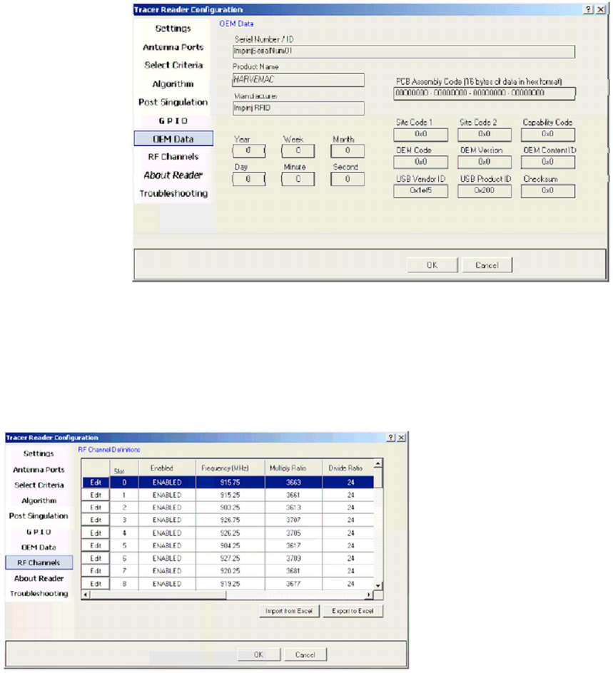
GPIO Pin Configuration Page
Use the GPIO Pin Configuration page to set and retrieve the current values of General
Purpose Input/Output (GPIO) pins which are accessible to the user on the Indy Firmware
microcontroller. The figure below shows the GPIO panel.
GPIO Pin Page
51
To retrieve the current value for a specific GPIO pin:
1.
Set the Access value to GET.
2.
Click the associated Apply button. The State column then indicates the retrieved
value— LOW for a binary value of zero or HI for a binary value of one. If the operation
fails, the Status field indicates this and the displayed state changes to UNKNOWN.
To retrieve the current values of all GPIO pins:
Click the Read All button. This operation sets all pins to GET mode and retrieves the
current
values from the system.
To set a value for a specific GPIO pin:
1.
Change the Access value to SET.
2.
Change the State field to the desired value.
3.
Click the associated Apply button.
OEM Data Page
The OEM Data page allows the user to read product data from the OEM area on the Indy
Firmware microcontroller. The GPIO page is shown in the figure below.
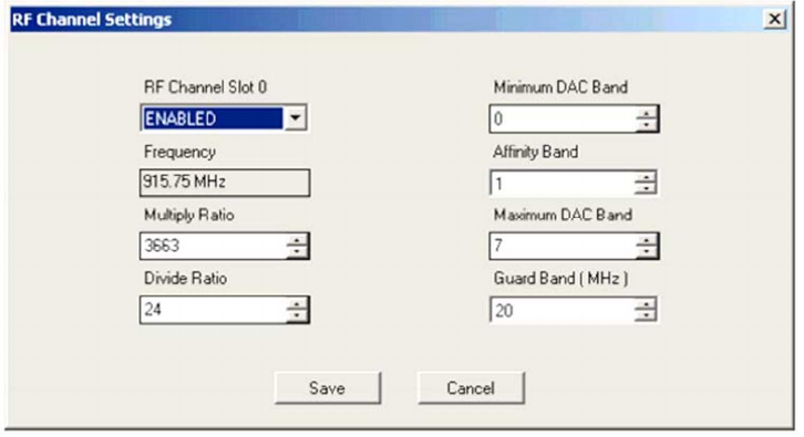
RF Channel Definitions
Page
OEM Data Page
The RF (Radio Frequency) Channel Definitions page provides a simplified method to view and
configure the reader’s frequency channels. An example of this page is shown below in the
figure below.
RF Channels Page
52
RF channels are identified and ordered by their slot number and displayed in a grid
format along with their current configuration values.
This dialog also allows you to import data from and export data to Microsoft Excel (using the
Excel XML format).
To edit a slot, click the Edit button next to the slot number. This displays the RF
Channels dialog box (shown in the figure below) from which the user can configure the
channel.
RF Channel Settings Dialog
Note that the channel frequency value is not directly editable by the user. Instead, this value
is dynamically calculated based upon the supplied multiply and divide ratios.
Other value limitations for fields presented on this page are as follows: • Divide Ratio can only
be set to a value of 1 or greater
Minimum DAC Band can only be set to value ranging from 0 to the current
value of
Maximum DAC Band inclusive
Affinity Band can only be set to values from the current Minimum DAC Band to
Maximum
DAC Band inclusive
Maximum DAC Band can only be set to values ranging from the current value of
Minimum
DAC Band to 7 inclusive
Note: When settings for a channel are saved, the specified Affinity Band is evaluated by the reader firmware. If
the firmware determines the Affinity Band is non-optimal, a new value between the Minimum DAC and Maximum
DAC Bands (inclusive) is generated and subsequently displayed on the RF Channels page.
53
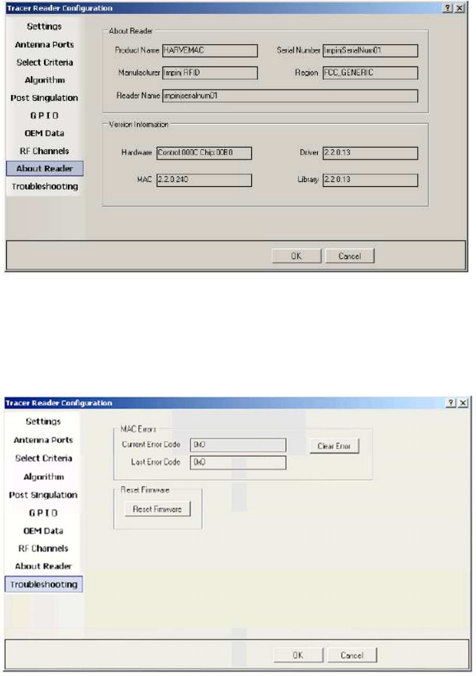
About Reader Page
The About Reader page is a static page that provides versioning information for the Indy
components of the reader. It provides a single place to find the version information for the
Indy device, Indy Firmware, Indy USB host driver, and Indy Host Library API Interface. The
figure below shows a sample About Page.
Troubleshooting
Panel
About Reader Page
The Troubleshooting page provides access to the Indy Firmware error register as well as the
ability to clear the error and reset the Indy Firmware. See the figure below.
Troubleshooting Page
Note: Performing a Reset Firmware operation causes a reset of the connection to the current reader. The reader
will no longer be accessible via the application until the application is restarted.
54
Register Access Panel
It is recommended that you have a very strong understanding of the behavior of the
underlying Indy Firmware prior to modifying register values directly via this method.
For more information, see the Indy_Firmware_Datasheet For the purpose of controlling and
configuring the reader, the Tracer application allows the user to read and write the various
Indy Firmware registers.
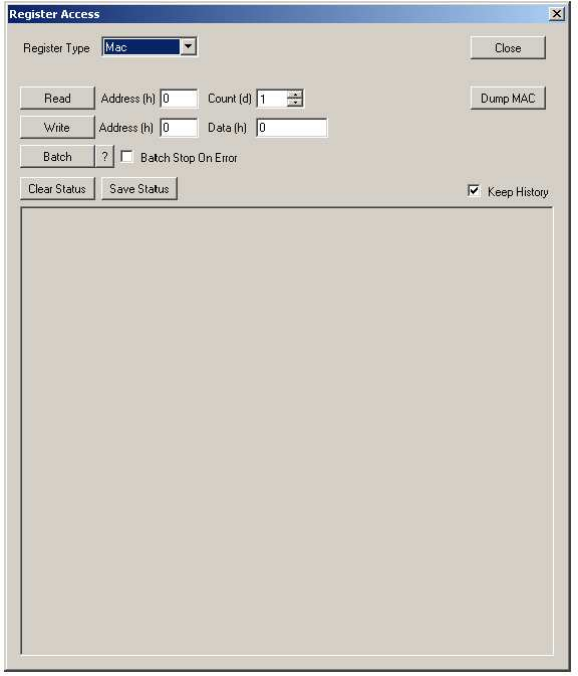
Register Type Mac
Selecting the Mac Register Access option displays the dialog shown in the figure below.
From this dialog, the user can perform read and write access to MAC Registers.
MAC Registers Page
To read an individual MAC register value:
Enter the hexadecimal start address and the total number registers to read.
Click the Read button. If a register cannot be read, for example because of an
invalid
address entry or the register is write-only, a read fail result will be displayed
in the status window.
To write an individual MAC register value:
Enter the hexadecimal start address and the hexadecimal value to write.
Click the Write button. If a register cannot be written, for example because of an
invalid
address entry or the register is read-only, a write fail result will be displayed
in the status window.
The Batch button allows for batch processing of multiple registers. Select the ? button
for Register Access Batch Help and file format.
55
The Dump MAC button reads all MAC registers and dumps the data in the status window.
The Clear Status button clears the status window.
The Save Status button allows the content of the status window to be saved to a file.
Check Keep History to retain all access history in the status window. Uncheck Keep History to
retain only the last access record in the status window.
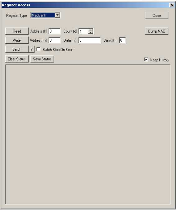
Register Type MacBank
Selecting the MacBank Register Access option displays the dialog shown in the figure below.
This dialog reduces the user input required to perform read and write access to MAC Banked
Registers.
MAC Banked Registers Page
56
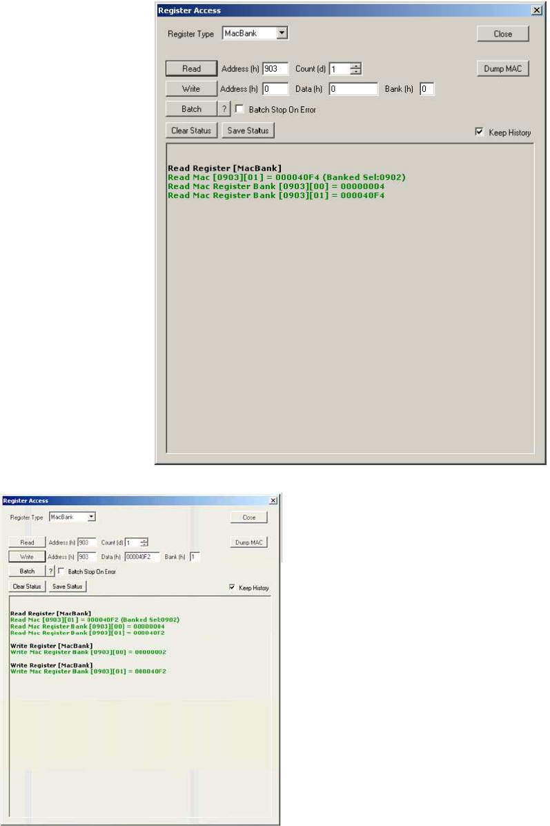
The configurable parameters for MAC Banked Register read operations are identical to those in
section 3.7.11.1. The figure below shows the status window for a valid banked register read,
detailing the currently selected bank, the applicable selector address, and the content of all
banks.
MAC Banked Register Read Status Example
The configurable parameters for MAC Banked
Register write operations are identical to those in
section 3.7.11.1, except that an additional bank
parameter is provided. This alleviates the need to
utilize the Mac Register Access dialog to select
the desired bank via the bank selector register
before performing banked register operations.
The figure below shows the status window for a
valid banked register read, detailing the currently
selected bank, the applicable selector address,
and the content of all banks. This is followed by a
write to each bank by simply changing the bank
index.
MAC Banked Register Read and
Write Status Example
57
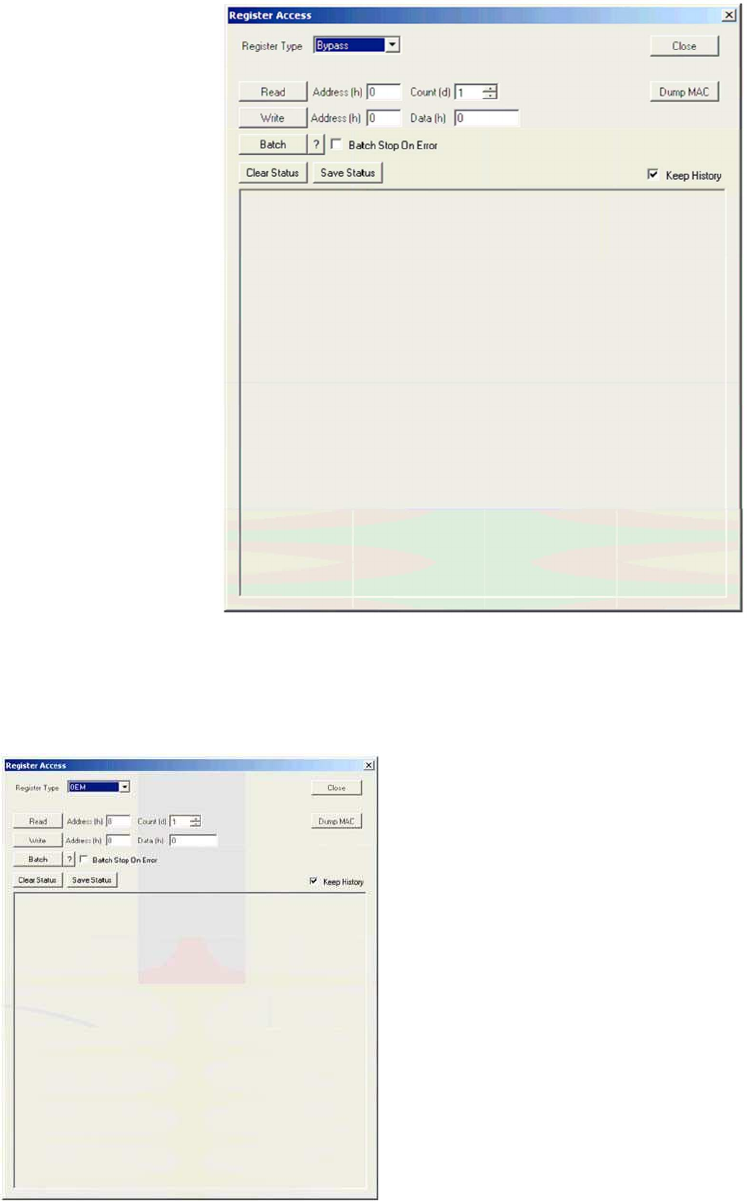
Register Type Bypass
Selecting the MacBypass Register Access option displays the dialog shown in the figure below.
From this dialog, the user can perform read and write access to Indy R1000 and R2000
Registers.
MAC Bypass Registers Page
The configurable parameters for Bypass Register read and operations are identical to those in
section 3.7.11.1.
Register Type OEM
OEM Registers Page
Selecting the OEM Register Access option displays
the dialog shown in the figure below. From this
dialog, the user can perform read and write access
to the OEM Registers.
58
The configurable parameters for OEM Register read and operations are identical to those
in section 3.7.11.1.
Register Type LinkProfile
Selecting the LinkProfle Register Access option displays the dialog shown in the figure below.
From this dialog, the user can perform read and write access to the registers of individual link
profiles.
LinkProfile Registers Page
The configurable parameters for OEM Register read and write operations are identical to
those in section 3.7.11.1, except that a Profile Id parameter is provided in order to perform
the read and write operations on a specific link profile.
Known Issues
The application does detect new readers that become active after the
application has
started. You should power on and connect your readers prior to
starting the Tracer application.
The names of detected readers are displayed as ASCII only in the Device menu.
Truncation is not supported in the Firmware Release v2.4.2, so selecting it in the
Select
criteria will render an error.

59
Federal Communications Commission (FCC) Statements:
This device complies with part 15 of the FCC Rules. Operation is subject to the following two conditions: (1) this
device may not cause harmful interference, and (2) this device must accept any interference received, including any
interference that may cause undesired operation of the device.
This equipment has been tested and found to comply with the limits for a Class B digital device, pursuant to part 15 of
the FCC rules. These limits are designed to provide reasonable protection against harmful interference in a residential
installation. This equipment generates, uses and can radiate radio frequency energy and, if not installed and used in
accordance with the instructions, may cause harmful interference to radio communications. However, there is no
guarantee that interference will not occur in a particular installation.
If this equipment does cause harmful interference to radio or television reception, which can be determined by turning
the equipment off and on, the user is encouraged to try to correct the interference by one or more of the following
measures:
-Reorient or relocate the receiving antenna.
-Increase the separation between the equipment and receiver.
-Connect the equipment into an outlet on a circuit different from that to which the receiver is
connected.
-Consult the dealer or an experienced radio/TV technician for help.
FCC Warning: The FCC requires that you be notified that any changes or modifications to this device not expressly
approved by the manufacturer could void the user’s authority to operate the equipment.
RF Radiation Exposure Statement:
This equipment complies with FCC RF radiation exposure limits set forth for an uncontrolled environment. This
equipment should be installed and operated with a minimum distance of 20 centimeters between the radiator and your
body.
This Transmitter must not be co-located or operating in conjunction with any other antenna or transmitter.
Only those antennas with same type and lesser gain filed under this FCC ID number can be used with this device.
The final system integrator must ensure there is no instruction provided in the user manual or customer documentation
indicating how to install or remove the transmitter module.
End Product Labeling
This transmitter module is authorized only for use in device where the antenna may be installed such that 20 cm
may be maintained between the antenna and users. The final end product must be labeled in a visible area with
the following: “Contains FCC ID: WK4FRU4100Q”. The grantee's FCC ID can be used only when all FCC
compliance requirements are met.
Manual Information That Must be Included:
The OEM integrator has to be aware not to provide information to the end user regarding how to install or remove. This
RF module in the user’s manual of the end product which integrates this module. The user’s manual for OEM
Integrators must include the following information in a prominent location