MATRIX COMSEC PVT VP310 SPARSH VP User Manual SPARSH VP310 QIG FCC
MATRIX COMSEC PVT. LTD. SPARSH VP SPARSH VP310 QIG FCC
Contents
- 1. User Manual
- 2. User Manual Rev 1.0
User Manual Rev 1.0
Thank you for choosing SPARSH VP310! Please read this guide first for correct
installation and retain it for future reference. The information in this guide was
current at the time of publication. All specifications are subject to change
without notice.
This Guide is meant to help you install and connect the phone. For detailed
installation instructions, refer to the System Manual.
Copyright
All rights reserved. No part of this document may be copied or reproduced in any form
or by any means without the prior written consent of Matrix Comsec Pvt. Ltd.
Warranty
Limited Warranty. Valid only if primary protection is provided, mains supply is within limit
and protected, and environment conditions maintained within product specifications.
Complete warranty statement is available on our website: www.MatrixTeleSol.com
SELECT A LOCATION
Step 1
Ÿ Phone, Handset and Spring Cord
Ÿ Ethernet Cable
Ÿ Power Adapter (5V,2.0 Amp)
Ÿ A Foot Stand
Ÿ A Warranty Card Set
Ÿ Wall Mounting Template
Ÿ Quick Installation Guide (printed copy)
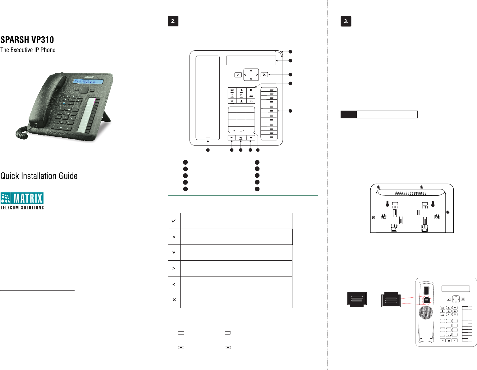
Know Your SPARSH VP310 What Your Package Contains
Installing SPARSH VP310
You can mount the phone on a wall or on the desk.
Mount SPARSH VP310 on a Wall
Ÿ Use the mounting template to drill holes of appropriate size and distance.
Ÿ Fix the screw grips in the holes you drilled.
Ÿ Fix two screws in the holes on the wall, ensuring that they are aligned
with the Keyhole Slots 1 and 2 of SPARSH VP310. The screws should
protrude from the wall to fit into the Keyhole Slots.
Ÿ Now, mount the phone with the screws fitting into the Keyhole Slot.
Ÿ Reverse the handset wall mount tab to make sure the handset remains
intact when you mount the phone. Push the handset wall mount tab
upwards to remove it from the slot. Rotate it 180 degrees clockwise and
push it downwards into the slot.
8
DSS
01
DSS
12
DSS
02
DSS
03
DSS
04
DSS
05
DSS
06
DSS
07
DSS
08
DSS
09
DSS
10
DSS
11
1 2 3
456
78 9
0
*#
abc def
ghi jkl mno
pqrs tuv wxyz
1
6
Volume decrease key
Volume increase key
Speaker key
LCD Screen
Ringer LED
Fixed Function keys
Dial Pad
DSS keys
1
2
3
4
5
7
8
9
Navigation keys
Handset
While talking,
Press to increase and press to decrease Speech volume.
When the phone rings,
Press to increase and press to decrease Ringer volume.
Volume Keys
Navigation Keys
The Enter Key;
To enter the Menu.
To make a selection in the Menu or to complete an action.
The Up Key;
To scroll upwards when navigating the Menu/sub-menu.
To access Phone Settings and set Ringtone/Play Key Tone.
The Down Key;
To scroll downwards when navigating the Menu/sub-menu.
The Forward Key;
To move the cursor.
The Back Key;
To move the cursor.
To go back one level in the Menu.
The Cancel Key;
To abort a function or process.
To exit a Menu.
Keyhole
Slot 2
Keyhole
Slot 1
5
7 6910
3
4
2
1
6
10
Wall Mount
On the Desk
DSS
DSS
DSS
DSS
DSS
DSS
DSS
DSS
DSS
DSS
DSS
DSS
1 2 abc 3def
4ghi 5jkl 6mno
7pqrs 8tuv 9wxyz
#
*0
Router /
LAN Switch
Computer
5VDC--2A
LAN PC
Adapter
MATRIX COMSEC
Head Office
394-GIDC, Makarpura, Vadodara - 390010, India
Ph:+91 265 2630555
E-mail: Support@MatrixComSec.com
www.MatrixTeleSol.com
Version 1, December 2015.
4. 5.
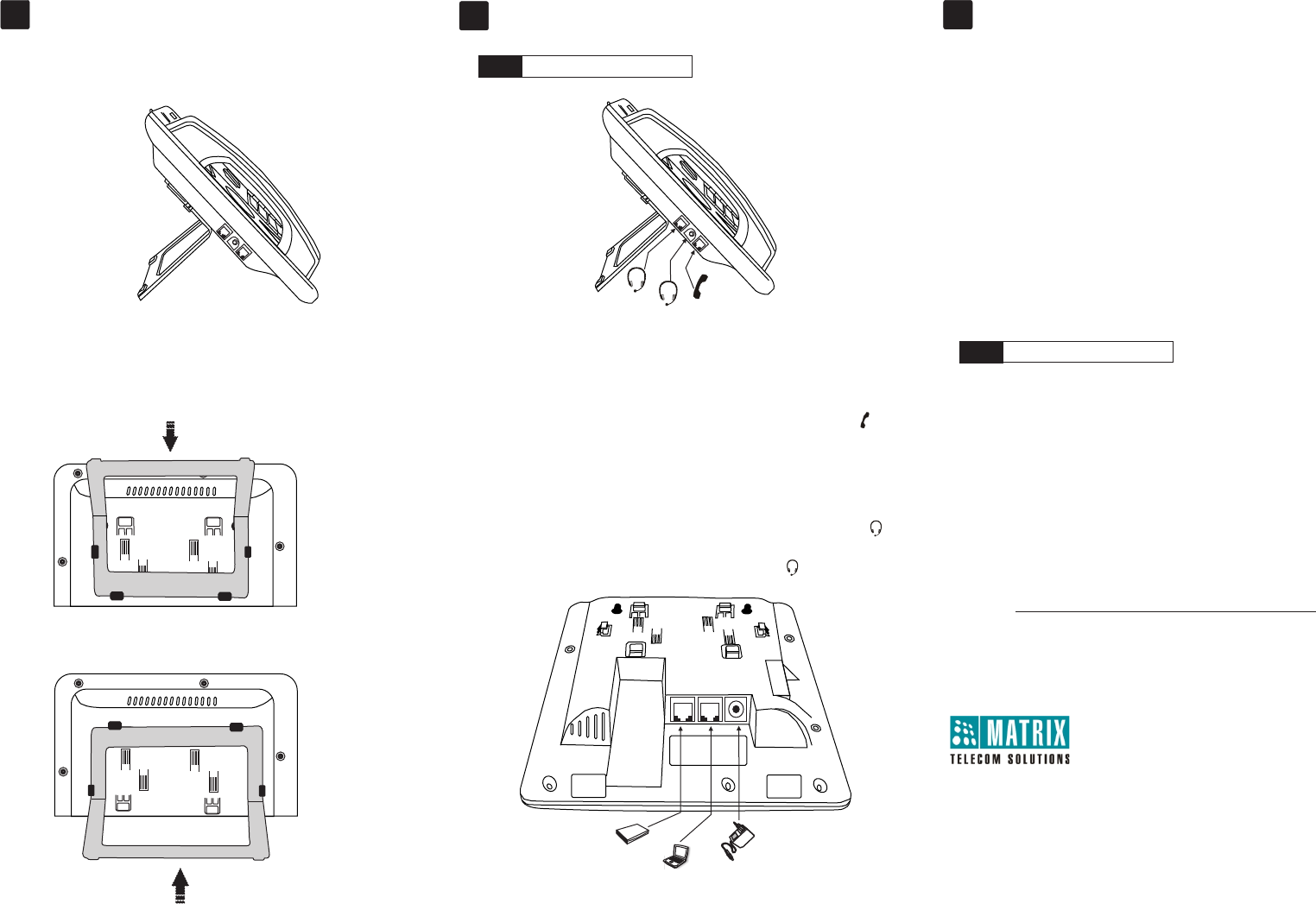
Connect the Headset (not supplied by Matrix)
If you want to use a Headset,
Ÿ Plug any standard stereo headset with 3.5mm single connector into the
headset jack on the left side panel of the phone, marked with the symbol .
Ÿ You may also plug in a headset with RJ9 connector into the headset port on
the left side panel of the phone, marked with the symbol .
6.
CONNECT
Step 2
Handset
Headset
Headset
Stand attached at
35 degree angle
Stand attached at
50 degree angle
Ÿ You can attach the Foot Stand in the following ways - at an angle of 35
degrees and 50 degrees.
STARTUP AND OPERATE
Step 3
Ÿ When the IP Phone is connected to the network and supplied with power, the
booting process initiates.
Ÿ After loading the application, the phone obtains the Network Settings,
updates the Firmware (if required), obtains the Configuration and then
attempts to register.
Ÿ To configure and register the phone as a SIP Extension, refer to the
System Manual. For operating instructions refer to the
EON48_310_SPARSH VP248_310_User Guide.
The documentation can be
found at http://www.matrixtelesol.com/technical-document.html
Connect the IP Network
Ÿ Connect the LAN Port of the phone to the IP Network — A Router or LAN
Switch — using the Ethernet Cable.
Connect the Power Supply
Ÿ Plug in the connector of the Adapter provided with the phone into the power
jack (DC Jack) with the label 5VDC-2A at the bottom of the phone.
Ÿ Plug in the Power Adapter into a power outlet.
Ÿ PoE enabled phone can be powered over Ethernet by connecting it to a PoE
enabled LAN Switch (IEEE 802.3af Compliant). In this case you need not
connect the Power Adapter.
Note: If both the power options, that is, PoE as well as Power Adapter are
available to the phone, then the phone will derive power from the PoE
enabled LAN Switch.
Connect the Handset
Ÿ Connect the handset of the EON310 to the phone body using the Spring
Cord (supplied with the phone).
Ÿ Connect the long straightened end of the Spring Cord into the RJ9
connector on the left side panel of the phone, marked with the symbol .
Mount SPARSH VP310 on the Desk
Connect a PC to the Phone
Ÿ Plug in the Ethernet Cable into the PC Port of the phone and the other end into
the LAN Port of your PC.
47CFR FCC PART 15B
Information to the user
(a) For a Class A digital device or peripheral, the instructions furnished the user shall include the following or similar statement, placed in
a prominent location in the text of the manual:
Note: This equipment has been tested and found to comply with the limits for a Class A digital device, pursuant to Part15 of the FCC
Rules. These limits are designed to provide reasonable protection against harmful interference when the equipment is operated in a
commercial environment. This equipment generates, uses, and can radiate radio frequency energy and, if not installed and used in
accordance with the instruction manual, may cause harmful interference to radio communications. Operation of this equipment in a
residential area is likely to cause harmful interference in which case the user will be required to correct the interference at his own
expense.
(b) For a Class B digital device or peripheral, the instructions furnished the user shall include the following or similar statement, placed in
a prominent location in the text of the manual:
Note: This equipment has been tested and found to comply with the limits for a Class B digital device, pursuant to Part 15 of the FCC
Rules. These limits are designed to provide reasonable protection against harmful interference in a residential installation. This
equipment generates, uses and can radiate radio frequency energy and, if not installed and used in accordance with the instructions,
may cause harmful interference to radio communications. However, there is no guarantee that interference will not occur in a particular
installation.
If this equipment does cause harmful interference to radio or television reception, 33 which can be determined by turning the equipment
off and on, the user is encouraged to try to correct the interference by one or more of the following measures:
Ÿ Reorient or relocate the receiving antenna.
ŸIncrease the separation between the equipment and receiver.
ŸConnect the equipment into an outlet on a circuit different from that to which the receiver is connected.
ŸConsult the dealer or an experienced radio/TV technician for help.