MC10 BRCS02 BRCS02 wearable sensor patch (WSP) User Manual
MC10 INC BRCS02 wearable sensor patch (WSP)
MC10 >
User Manual
Instructions for Use

2
BioStamp nPoint User Manual
3
BioStamp nPoint User Manual
Only

4
BioStamp nPoint User ManualBioStamp nPoint User Manual
Table of Contents
Introduction, Safety, and Component Overview.....................................................6
System Description..................................................................................................7
Important Safety Information..............................................................................8
Indications for Use..................................................................................8
Contraindications....................................................................................8
Warnings....................................................................................................8
Precautions................................................................................................9
Storage and Handling............................................................................9
Device and Packaging Symbols and Markings..........................10
Regulatory I nformation........................................................................................13
Applicable Standards..........................................................................13
FCC Compliance Notication........................................................... 13
BioStamp nPoint Platform Components.......................................................14
BioStamp nPoint Component Assembly and Function Overview.......15
Link Hub.................................................................................................. 15
Tablet.........................................................................................................16
Sync Phone..............................................................................................16
Link Phone...............................................................................................17
BioStamp Sensors.................................................................................18
Adhesives.................................................................................................20
Maintenance.............................................................................................................24
Upgrading System Components.....................................................24
Cleaning and Disinfection.................................................................24
Executing a Study.................................................................................................................26
Investigator Portal Study Design......................................................................27
Run a Supervised Study.......................................................................................30
Run a Remote Study..............................................................................................35
Subject Assessment and Data Analysis..........................................................38
Troubleshooting and Manufacturer............................................................................42
Troubleshooting.....................................................................................................43
Manufacturer...........................................................................................................43
Appendix A..............................................................................................................................44
BioStamp nPoint Platform Components.......................................................45
BioStamp nPoint Component Service Life..................................45
Technical Specications.......................................................................................46
BioStamp Technical Specications.................................................46
BioStamp Recording Modes.............................................................47
Adhesive Technical Specications..................................................47

5
BioStamp nPoint User Manual
Link Hub and BioStamp Sensor Frequency and
Transmission Specications..............................................................48
Hardware LED Status Indicator Table............................................48
EMC Declaration and Guidance........................................................................49
Guidance and Manufacturer’s Declaration –
Electromagnetic Emissions...............................................................49
Guidance and Manufacturer’s Declaration –
Electromagnetic Immunity...............................................................50
Appendix B.............................................................................................................................. 53
Portable Emissions Measurement System (PEMS) connection to an
IT-Network................................................................................................................54
Implemented Protocols ......................................................................................54
Information Flow .................................................................................................. 54
Hazardous Situations............................................................................................55

Introduction,
Safety, and
Component
Overview
7
BioStamp nPoint User Manual
BioStamp nPoint is a wireless remote monitoring platform intended for use
by healthcare professionals and researchers for the continuous collection
of physiological data in healthcare and home settings. BioStamp nPoint is
designed to capture objective, real-world data from study subjects
participating in clinical or academic studies, and may be used wherever
collection of relevant data is needed.
BioStamp nPoint centers on body-worn BioStamp Sensors that can be worn
for up to 24 hours at a time in both laboratory (clinic) and home settings.
Investigators (either researchers or physicians) design studies and the data to
be collected using a web-based study conguration tool, called the
Investigator Portal. For laboratory or clinic (“Supervised”) settings, BioStamp
nPoint includes a Tablet Investigator Application (“Investigator App”) to be
used for the set-up and conguration of the sensors. When BioStamp nPoint
is used in the home or outside of the clinic (“Remote”) setting, study subjects
interact with the system through a Mobile Phone Application called the
“Link App.” The recharging and data transmission hub (“Link Hub”) is used to
recharge the sensors and synchronize data from the Sensors. BioStamp nPoint
includes an algorithm package that delivers a dashboard presentation of
processed metrics on general activity (including step count and activity
classication), heart rate, heart rate variability, posture (body position relative
to gravity), sleep, and respiration during sleep. The system is also capable
of surface electromyography and monitoring limb and body movements
during daily living and sleep. Data are transmitted wirelessly from the Sensors
through the Link Hub to the MC10 Cloud for storage, processing, and analysis.
System Description

8
BioStamp nPoint User Manual
Important Safety Information
Indications for Use
The BioStamp nPoint system is a wireless remote monitoring system intended
for use by researchers and healthcare professionals for continuous collection
of physiological data in home and healthcare settings. These physiological
data include heart rate, heart rate variability, respiration rate, activity
(including step count and activity classication), and posture (body position
relative to gravity). The system is also intended for measurement of surface
electromyography and to monitor limb or body movements during daily
living and sleep. Data is transmitted wirelessly from the Sensors for storage
and analysis.
The device is intended for use on general care patients who are 18 years of
age or older as a general patient monitor to provide physiological
information. The data from the BioStamp nPoint system is intended for use
by researchers and healthcare professionals for research applications or, at
the discretion of a qualied healthcare professional, as an aid to diagnosis and
treatment. The device is not intended for use on critical care patients.
Contraindications
The device is not intended for use on:
• patients who have implanted pacemakers or debrillators
• patients with known allergies or hypersensitivities to adhesives or
hydrogel
Warnings
• The wearable sensor may cause mild discomfort, skin irritation, redness,
itching, rash or contact dermatitis in some individuals. The device should
be removed if any pain or discomfort occurs.
• Histories of skin irritations should be considered prior to placing the
wearable sensor on a patient
• The wearable sensor should not be applied to broken, damaged, or
• irritated skin.
• The wearable sensor should be removed prior to external debrillation or
an MRI scan and should not be used in the presence of strong
• electromagnetic elds.
• Keep Link Hub components, tablet, and mobile devices away from water
and other liquids.
• No modication of this equipment is allowed.
• Clinical validation has not been performed on children or on patients
who are pregnant or breastfeeding.

9
BioStamp nPoint User Manual
Precautions
• The wearable sensor should be removed prior to external debrillation or
an MRI scan.
• Sensors and Adhesive Stickers are non-sterile. Adhesives are single use
only on a single patient.
• Do not apply the wearable sensor if it appears damaged
• Similar devices may cause signal interference during data transmission. If
you experience this aect, avoid operating near interfering devices.
• Do not wear the device over regions of the body with excessive body hair.
Excessive body hair should be removed prior to wear.
• No creams or lotions should be applied to the skin immediately prior to
application of the wearable sensor
• Keep the device away from children and pets. The device may be a
• choking hazard, and may be harmful if swallowed.
• If any component of the BioStamp nPoint system fails to operate after
attempting all suggested troubleshooting methods, contact your health
care provider and/or study sta immediately.
• The battery used in this device may present a risk of re, explosion or
chemical burn if mistreated. Do not expose to excessive heat or re. Do
not crush, puncture, or incinerate as doing so can result in re, explosion,
or the release of toxic gases. Do not use or charge if unit appears to be
leaking, discolored, deformed, or in any way abnormal.
• Return all components of the BioStamp nPoint system to your health care
provider and/or study sta at the conclusion of your prescribed period of
use.
• Dispose of the BioStamp nPoint system per local laws, care facility laws or
hospital laws for routine/non-hazardous electronic waster.
Storage and Handling
• Storage temperature range: 15 – 30°C
• Storage relative humidity range: 40 – 60% RH
• Ensure your hands are clean and dry before handling any system
• components. Gloves are recommended for healthcare professionals
when handling the wearable sensor.
Changes or modications made to this equipment not express-
ly approved by the party responsible for compliance could void
the user’s authority to operate the equipment. Note
10
BioStamp nPoint User Manual
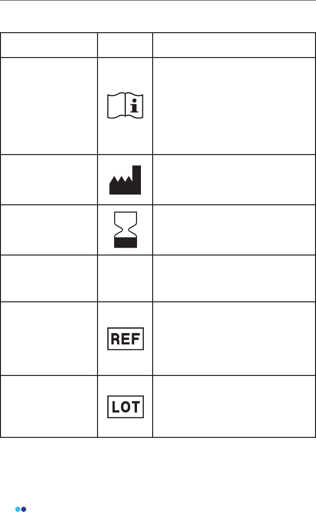
Device and Packaging Symbols and Markings
Meaning Symbol Description
Instructions for Use
To identify the location where the
operator’s manual is stored or to
identify information that relates to
the operating instructions. To indicate
that the operating instructions should
be considered when operating the
device or control close to where the
symbol is placed.
Manufacturer
To identify the manufacturer of a
product. This symbol shall be used
lled in all applications to dierentiate
it from ISO 7000-2497.
Use by Date
To indicate that the device should not
be used after the date accompanying
the symbol, for example on a medical
device or its packaging.
Ingress Protection
Rating
This symbol indicates the ingress
protection rating of the Link Hub
Catalogue Number
To identify the manufacturer’s
catalogue number, for example on a
medical device or the corresponding
packaging. The catalogue number
shall be placed adjacent to the
symbol.
Batch Code
To identify the manufacturer’s batch
or lot code, for example on a medical
device or the corresponding
packaging. The code shall be placed
adjacent to the symbol.
IP24
11
BioStamp nPoint User Manual
Meaning Symbol Description
Serial Number
To identify the manufacturer’s serial
number, for example on a medical
device or its packaging. The serial
number shall be placed adjacent to
the symbol.
Choking Warning
Symbol
Keep out of reach of children; choking
hazard for children ages 0-3 years.
Electrical Safety
Classication
To identify a type BF applied part
complying with IEC 60601-1. The
BioStamp Sensor is a Type BF Applied
Part.
ON/OFF Symbol
To indicate connection to or
disconnection from the mains, at least
for mains switches or their positions,
and all those cases where safety is
involved. Each position, “ON” or “OFF”,
is a stable position.
For Indoor Use Only To identify electrical equipment
designed primarily for indoor use.
Follow Operating
Instructions
To signify that the instruction manual/
booklet must be read.
Temperature
Limitations
To indicate the maximum and
minimum temperature limits at which
the item shall be stored, transported
or used.
Upper Temperature
Limitation
To identify the maximum temperature
limit. The temperature value may be
shown adjacent to the symbol.
12
BioStamp nPoint User Manual
Meaning Symbol Description
Lower Temperature
Limitation
To identify the minimum temperature
limit. The temperature value may be
shown adjacent to the symbol.
Direct Current
To indicate on the rating plate that
the equipment is suitable for direct
current only; to identify relevant
terminals.
Do Not Re-Use
To indicate that the item is for single
use only and must not be used more
than once, for example on packages
of medical disposables.
Humidity Limitation
To indicate the acceptable upper and
lower limits of relative humidity for
transport and storage.
Atmospheric Pressure
Limitation
To indicate the acceptable upper and
lower limits of atmospheric pressure
for transport and storage.
13
BioStamp nPoint User Manual
Regulatory Information
Applicable Standards
Standard Description
IEC 60601-1 Labeling Requirements; Safety Testing
IEC 62366 Usability Engineering for Medical Devices
FCC Compliance Notication
The BioStamp nPoint System was veried for RF exposure and found to com-
ply with Council Recommendation 1999/519/EC and FCC OET-65 RF exposure
requirements. This equipment complies with FCC radiation exposure limits set
forth for an uncontrolled environment.
This equipment has been tested and found to comply with the limits for a
Class B digital device, pursuant to part 15 of the FCC Rules. These limits are
designed to provide reasonable protection against harmful interference in
a residential installation. This equipment generates, uses and can radiate
radio frequency energy and, if not installed and used in accordance with
the instructions, may cause harmful interference to radio communications.
However, there is no guarantee that interference will not occur in a particular
installation. If this equipment does cause harmful interference to radio or tele-
vision reception, which can be determined by turning the equipment o and
on, the user is encouraged to try to correct the interference by one or more of
the following measures:
• Reorient or relocate the receiving antenna;
• Increase the separation between the equipment and receiver;
• Connect the equipment into an outlet on a circuit dierent from that to
which the receiver is connected;
• Consult the dealer or an experienced radio/TV technician for help.
The BioStamp Sensors comply with Part 15 of the FCC Rules. The included
Link Hub complies with Part 15 and Part 18 of the FCC Rules. Operation of
each device is subject to the following two conditions: (1) this device may not
cause harmful interference, and (2) this device must accept any interference
received, including interference that may cause undesired operation.
14
BioStamp nPoint User Manual
Documentation Instructions for Use
Subject Instructions for Use for Remote Studies
Core Components
and Accessories
Link Hub and Power Supply
BioStamp Sensors
Adhesive Stickers
Adhesive Applicator
Investigator Web Portal (MDDS or MC10 Cloud)
Supervised Components
Tablet with Investigator Application and Tablet
Charger
Mobile Phone with Sync Application
Remote Components Mobile Phone with Link Application
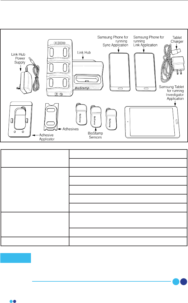
BioStamp nPoint Platform Components
Remote components of BioStamp nPoint are intended for
operational use by the patient. Supervised components of
BioStamp nPoint are intended for operational use by
investigators.
Note
BioStamp nPoint includes the following components:
15
BioStamp nPoint User Manual
BioStamp nPoint Component Assembly
and Function Overview
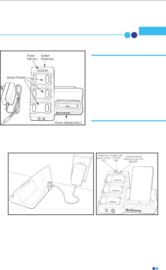
Link Hub
The Link Hub stores captured data from each Sensor on an internal SD
memory card. When the Link or Sync Phone is connected to the Link Hub,
data from the Sensors can be transferred via a cellular or Wi-Fi connection to
the MC10 Cloud.
To assemble the Link Hub with power supply, set the Link Hub on a at, stable
surface. Do not position the Link Hub so that it is dicult to unplug the power
supply cord. Plug the provided Link Hub power supply into the back of the
Link Hub, and insert the wall adapter plug end into a nearby outlet. To power
down, unplug the power supply cord from the Link Hub.
Ensure system components are fully charged before each use. Note
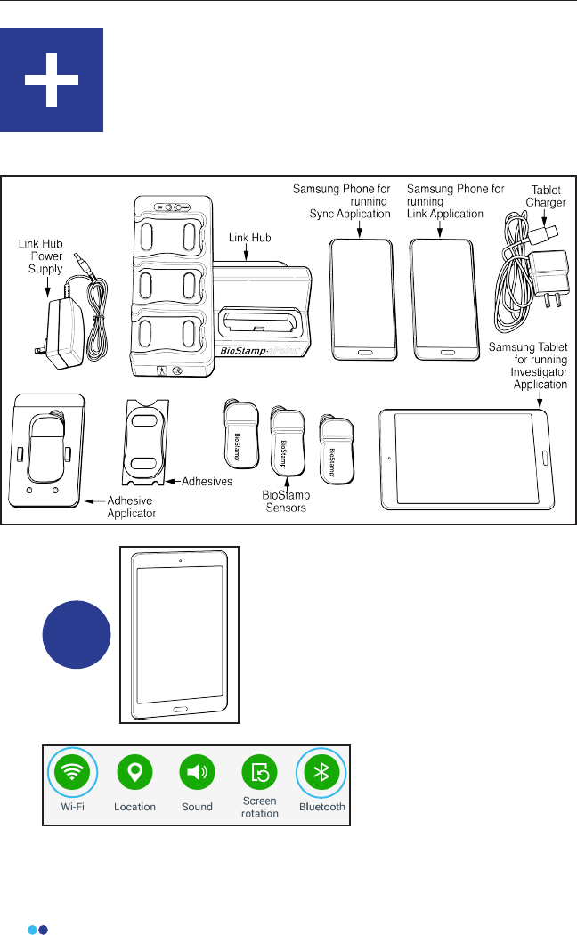
BioStamp nPoint includes a
charging platform, called the Link
Hub that holds and charges the
Link Phone (for Remote Studies),
Sync Phone (for Supervised
Studies) and the BioStamp
Sensors. The Link Hub also
synchronizes data from three
Sensors and the Phone
simultaneously.
16
BioStamp nPoint User Manual
Tablet
The tablet is congured with the Android operating system (do not exchange
or alter) and the Investigator Application. The Investigator App is synchro-
nized to the study parameters set by the investigator in the Investigator Portal
any time a study is accessed. For Supervised Studies, the investigator uses the
Investigator App to assign Sensors to subjects and to initiate recordings.
Subject information in the form of activity tags and survey entries can be
entered using the Investigator App. For full functionality, the tablet must be
connected to a Wi-Fi network and have Bluetooth turned on.
You can log in to the Investigator App using your BioStamp nPoint credentials
and log out through the Investigator App settings. Turn o the tablet by
holding down the power button and selecting the “power o” option.
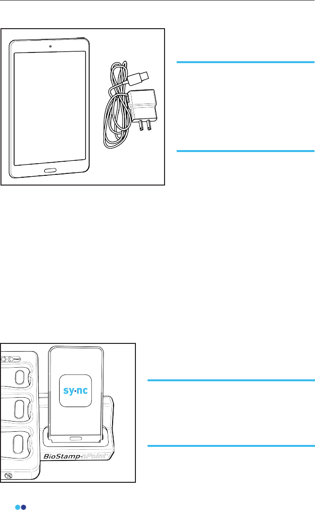
Sync Phone
For Supervised Studies, BioStamp
nPoint comes with a Samsung
Galaxy Tab A tablet (and charger)
for running the Investigator App,
a tool used to communicate with
Sensors and run studies in the
clinic or lab.
For Supervised Studies, BioStamp nPoint
comes with a Samsung Galaxy J3
smartphone for running the Sync App,
used to upload study data collected in
the clinic or lab.
17
BioStamp nPoint User Manual
The Sync Phone is congured with the Android operating system (do not
exchange or alter) and the Sync Application. To charge the Sync Phone, place
it in the phone dock on the Link Hub. Once an investigator is logged into the
Sync App, the app is congured to upload Sensor data from the Link Hub to
the MC10 Cloud. For full functionality, the Sync Phone must be connected to a
data network (Wi-Fi, mobile, etc) and have Bluetooth turned on. You must be
an investigator to log in to the Sync App using your BioStamp nPoint cre-
dentials. To sign out press the “sign out” button in the Sync App. Turn o the
Sync Phone by holding down the power button and selecting the “power o”
option.
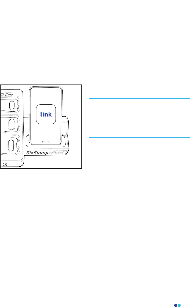
Link Phone
The Link Phone is congured with the Android operating system (do not
exchange or alter) and the Link Application. To charge the Link Phone, place
it in the phone dock on the Link Hub. Once a study subject is logged into the
Link App, the application is congured to the study parameters set by the
investigator in the Investigator Portal. The Link App displays a daily sched-
ule for the subject to complete including Sensor placement, survey entries,
prescribed activities, and Sensor removal. The Link App is also used to upload
Sensor data from the Link Hub to the MC10 Cloud. For full functionality, the
Link Phone must be connected to a data network (Wi-Fi, mobile, etc) and have
Bluetooth turned on.
You can generate a unique subject passcode on the Investigator Portal to use
to log in to the Link App. You can then provision a Remote Kit (Link Phone,
Link Hub, and Sensors) to a specic subject and track hardware status. Once
the subject has completed the prescribed program, you can reset the
hardware by following the reset instructions in the Link App settings menu.
For Remote Studies, BioStamp nPoint
comes with a Samsung Galaxy J3
smartphone for running the Link App,
used to guide subjects through study
activities and upload study data.
18
BioStamp nPoint User Manual
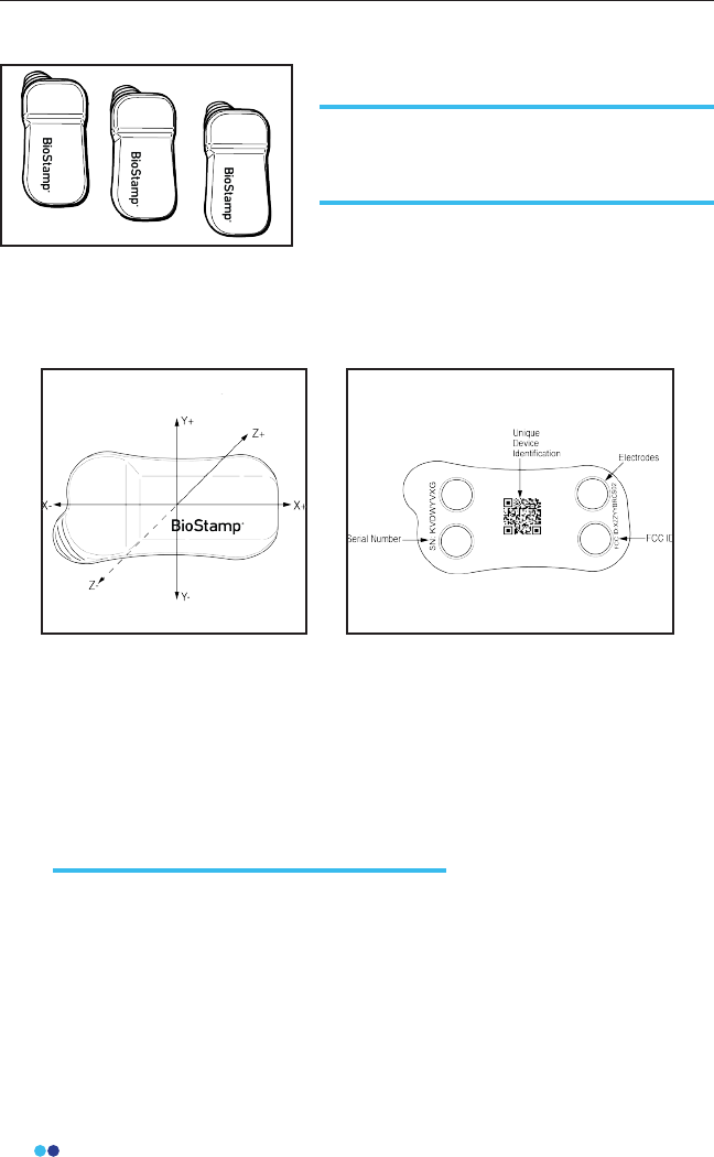
The Sensor is optimized for small size and low power operation. BioStamp
Sensors can collect biopotential (surface electromyography) and
accelerometry (limb and body movement) data.
Sensor Coordinate System Sensor Back View
The Sensor can be placed in numerous orientations in various locations, and
multiple Sensors can be placed on a single person. Once activated using the
Investigator App or Link App, each Sensor operates independently, storing
data in its local memory. The data can then be transferred wirelessly for
display and subsequent analysis. The Sensor is designed for use cases
involving up to 24 hours of continuous wear.
BioStamp Sensors
The BioStamp Sensor is an extremely thin,
body-worn system designed to measure
and record biometric signals.
Inspect Sensors
Inspect all Sensors for damage prior to use.
Damage includes cracked, split, or broken encapsulation; exposed
electronics other than the electrodes; tears or splits in the device; or any
other deviation from the manufactured state that might impair
functionality. Do not use Sensors that have visible damage.
19
BioStamp nPoint User Manual
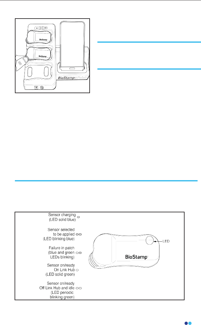
Power Sensors On and O
To power Sensors on, simply place the
Sensors in the sensor pockets on the
Link Hub.
BioStamp Sensors are shipped in a powered-o state. The LED light in
the upper right corner of the Sensor will be solid blue when charging
and solid green when ready.
For long-term storage, Sensors should be powered o. Sensors can be
powered o using the Investigator App on the tablet. Remove the
Sensor from the Link Hub before powering o. Sensors will
automatically turn o 3 hours after being removed from the Link Hub if
they are idle/ready for use and not set to record or if they are not ready
for use.
Sensor Status Indications
Sensors are equipped with a rechargeable battery. Before the Sensors
can be used, the user must ensure they are fully charged.
Charge Sensors
Charge Sensors by placing them in the sensor pockets on the Link Hub.
20
BioStamp nPoint User Manual
The adhesives are intended to adhere the Sensors to the body for up to 24
hours.
Under certain conditions the provided adhesive might not be sucient (e.g.
prolonged swimming, very intense exercise) to adhere the Sensors to the
body for the full 24-hour wear duration. The Dorsal Foot and Dorsal Hand
locations are particularly prone to adhesion issues due to the movement and
body morphology of these specic areas. MC10 recommends providing an
additional method of securing the Sensors to these body locations and for
use during certain activities.
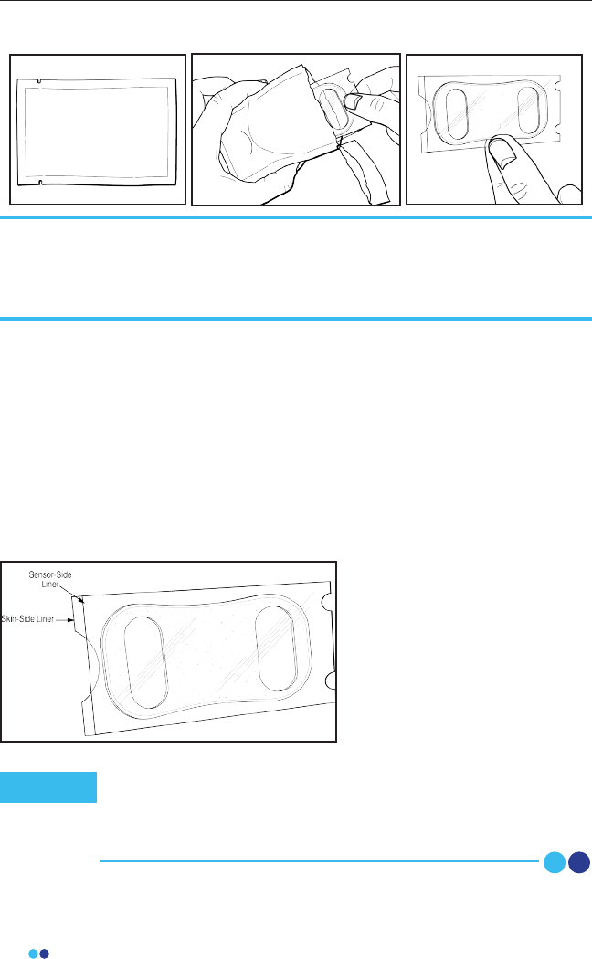
Apply the Adhesive Stickers
to Sensors
Each adhesive will be pack-
aged individually in a sealed
foil pouch. Do not open the
adhesive pouch until you are
ready to apply the adhesive to
the Sensor.
Adhesives
BioStamp Sensors are applied to the body using disposable adhesives for
attachment that also contain hydrogel to optimize electrode contact to the
skin. These double-sided adhesives have a sensor-side and a skin-side and
should be applied to the Sensor using the provided applicator as a guide.
For locations outside of the required analytics sensor locations
(see Investigator Portal Study Design), extra means to secure
the sensors to the body are recommended (e.g. TegadermTM,
CobanTM wrap).
Note
21
BioStamp nPoint User Manual
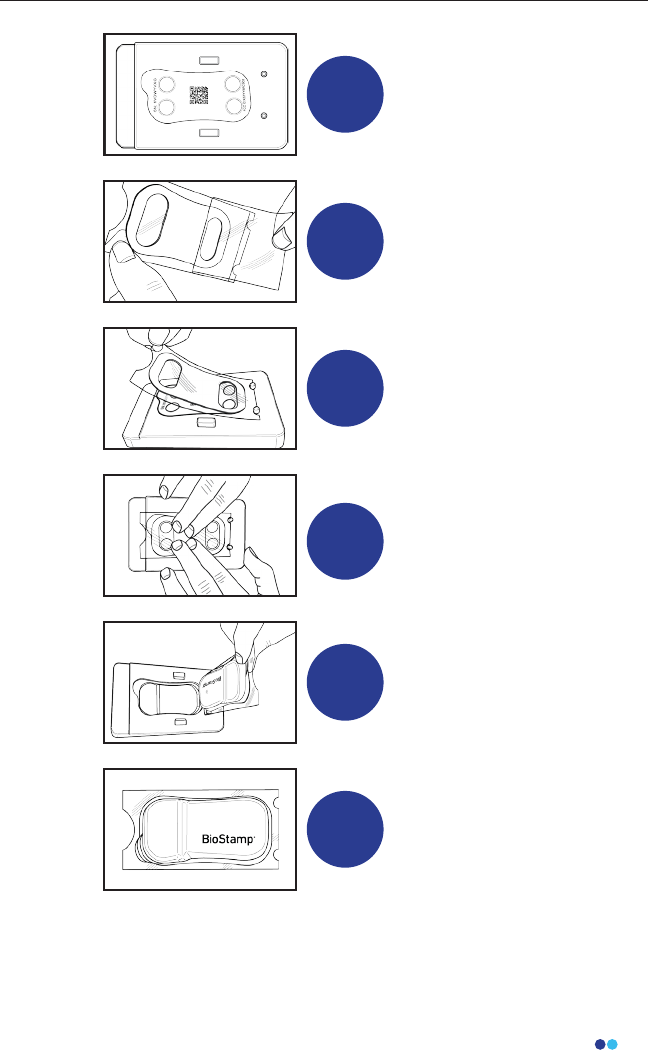
1
Place the adhesive
applicator guide on a at
surface. Fit the Sensor,
electrode side up, in the
applicator sensor pocket.
2Remove the labeled
sensor-side liner from the
adhesive sticker.
3
Align the two semi-circular
cutouts on the bottom side
of the remaining liner to the
applicator peg guides, and
lower the adhesive onto the
Sensor.
4
Press down rmly for at least
10 seconds on the edges
and middle of the sticker to
apply the adhesive to the
Sensor
5
Use the liner nger tabs to
remove the Sensor with
adhesive sticker from the
applicator pocket.
6
Leave the remaining
skin-side liner on the Sensor
until you are ready to apply
to the body location.
22
BioStamp nPoint User Manual
Alcohol wipes are not recommended as they dry the skin,
which reduces adhesion and electrode signal quality.
Additionally, using body lotion or other skin preparations may
interfere with Sensor adhesion.
Note
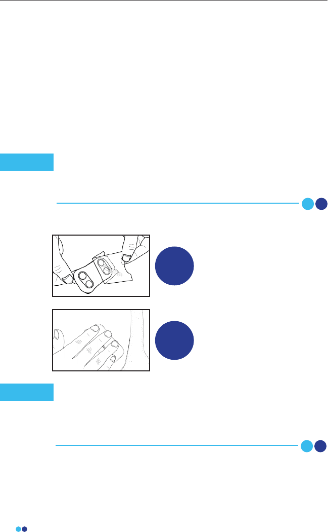
1
To apply, remove the re-
maining skin-side liner from
the Sensor and adhesive.
Be careful not to touch the
adhesive or electrode area.
2
Place the Sensor on the
target body location. Press
rmly on the Sensor for at
least 10 seconds.
Apply Sensor
The Sensor should stay in place by itself. If necessary, it can
be secured by a secondary method such as an adherent wrap
or tape. Do not wear the Sensor and adhesive for more than
24 hours without changing the adhesive and cleaning and
recharging the Sensor.
Note
Applying Sensors to Body
During Remote Studies, the subject may refer to the Link App and the
Subject Instructions for Use for Sensor application and removal
instructions.
Skin Preparation
Proper skin preparation improves Sensor adhesion and signal
quality. Before applying the Sensor, prepare the skin of the subject
by trimming any excess hair at the application site and cleaning
the site thoroughly with soap and water. Dry the area vigorously
before applying the Sensor.
23
BioStamp nPoint User Manual
The Sensor and adhesive should peel o cleanly. Any adhesive
residue on the skin can be removed with baby oil or alcohol-based
solvents. Remove the adhesive from the Sensor by peeling it away
using the Sensor hold tab and edge of the sticker. Dispose of the
adhesive sticker. Clean and disinfect Sensors between subjects.
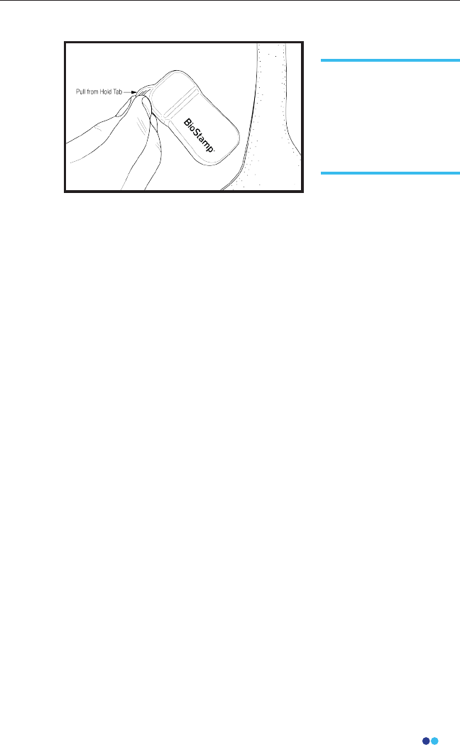
Remove Sensor
To remove a Sensor,
simply grab the hold
tab on the thicker end
of the Sensor and peel
the Sensor and adhe-
sive o the skin.
24
BioStamp nPoint User Manual
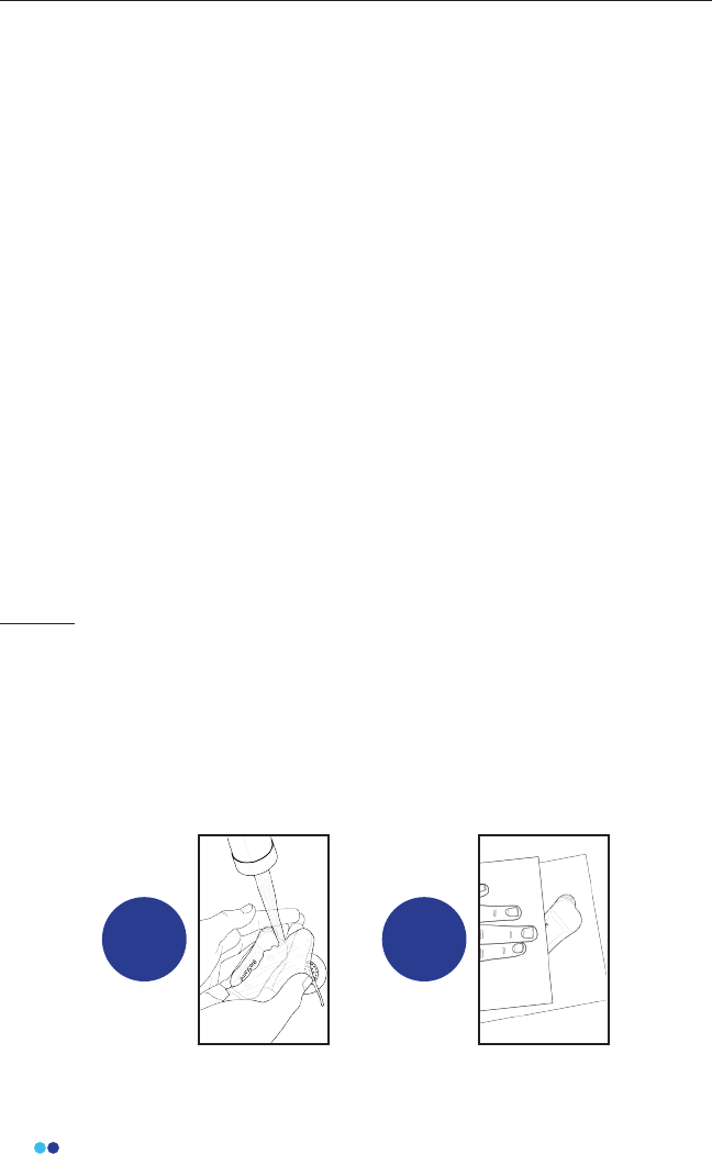
Subject
The subject should clean BioStamp Sensors after each use. Simply
remove and dispose of the one-time use adhesive sticker, wash the
Sensor by hand with hand-soap and warm water to remove visible dirt
and debris, and pat dry. Inspect sensors for any nicks, cuts, or tears, and
if present, do not reuse.
1 2
Maintenance
Upgrading System Components
In the event that an upgrade is needed for any component of BioStamp
nPoint (BioStamp Sensor, Link Hub, Link App, Sync App, Investigator App)
contact MC10, Inc.
When new software versions are available the mobile applications will instruct
you or the subject through the upgrade process. For Remote studies, the
software is checked during the subject setup and system reset processes.
Release notes of the changes are available in the app Update menu and
detailed engineering changes can be sent upon request.
Cleaning and Disinfection
The system may be reused across multiple subjects, and reusable components
must be cleaned and/or disinfected per instructions between subjects by the
responsible organization or service personnel. The minimum service
personnel requirements are an 8th grade education and the ability to read
English. Clean and/or disinfect component before any service procedure.
Sensors must be cleaned and charged before initial use. If you remove a
Sensor from a subject and plan to replace it later, clean the Sensor before
reuse. We recommend cleaning the Sensor prior to recharging.
DO NOT expose any component or part of the system to heat above 40°C,
dishwashers, clothes dryers, autoclaves, or other industrial cleaning processes.
25
BioStamp nPoint User Manual
Exposure to the following household chemicals will damage the Smart Char-
ger and should be avoided:
• Nail Polish remover, both acetone and ethyl acetate based formulations
• Sunscreen
• Insect repellents containing DEET
All components can be used until their marked expiration date. All expired
components except the adhesives should be returned to the manufacturer for
proper decommissioning and disposal.
1 2
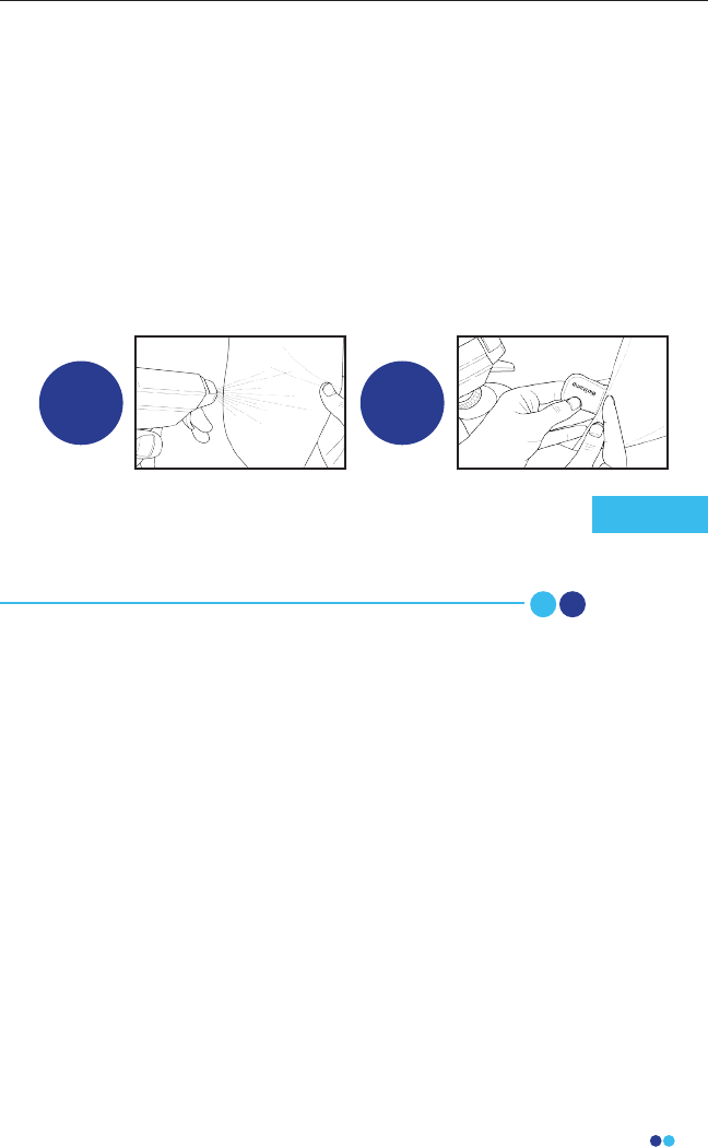
Investigator
In addition to the subject cleaning the Sensors with soap and water, the
Investigator should clean all Sensors and all Medical Electrical
equipment and certain accessories between each subject. To clean,
simply wipe down each component (BioStamp Sensor, Link Hub, Power
Supply, Link Phone, Sync Phone, Tablet, Adhesive Applicator) with an
alcohol wipe (70% Isopropyl Alcohol/30% De-ionized water) to remove
visible dirt and debris or use a cleanroom wipe sprayed with a 70%
isopropyl alcohol solution. Let all components dry, until no IPA is visible.
To further disinfect the BioStamp Sensor, use an additional alcohol
wipe and allow Sensor to dry before reuse.
BioStamp Sensors tolerate exposure to 70% isopropyl alcohol.
The adhesives may interact with residual alcohol, however. Be
sure to allow alcohol-exposed Sensors to dry thoroughly before
applying adhesives.
Note

Executing a Study
27
BioStamp nPoint User Manual
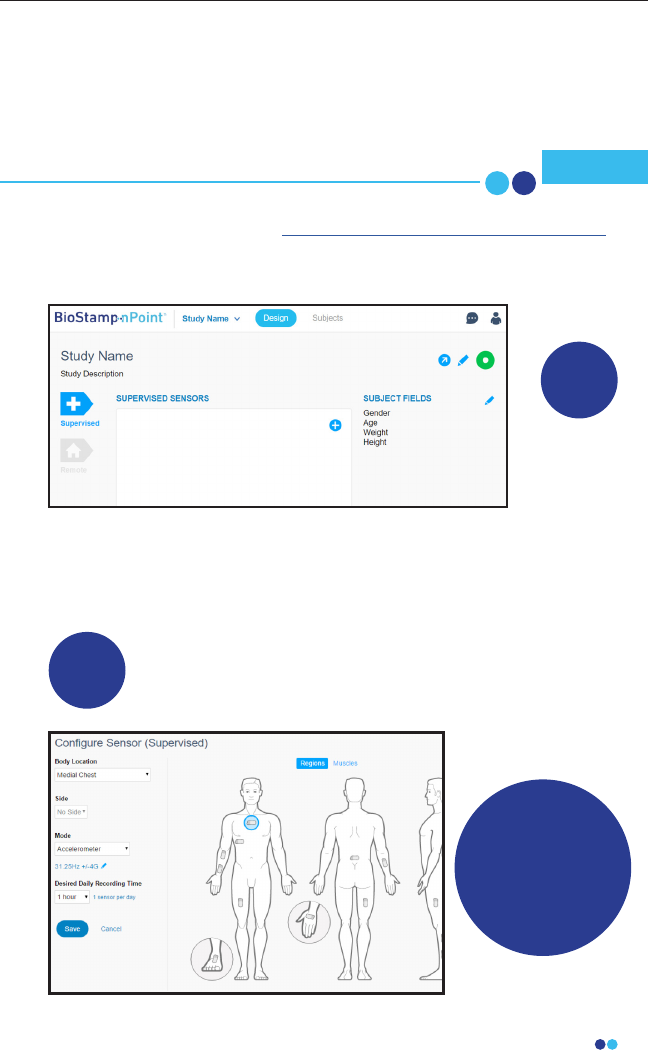
Investigator Portal Study Design
Log into the Investigator Portal at www.mc10cloud.com/biostampnpoint with
your credentials (email to set password sent upon purchase) to access the
BioStamp nPoint Software.
Design Study in the Investigator Portal
Congure Sensor
Recording Modes
and Locations
In the Design tab, click on New Study, provide a name and
description, and select either the Supervised or Remote environments
to begin designing your study.
1
2
Create
New Study
The Investigator Portal will be used by the investigator and sanctioned users
to design a study, view, and export data collected from study subjects.
Computers used to access the Web Portal should be appropri-
ately controlled against malware Note
28
BioStamp nPoint User Manual
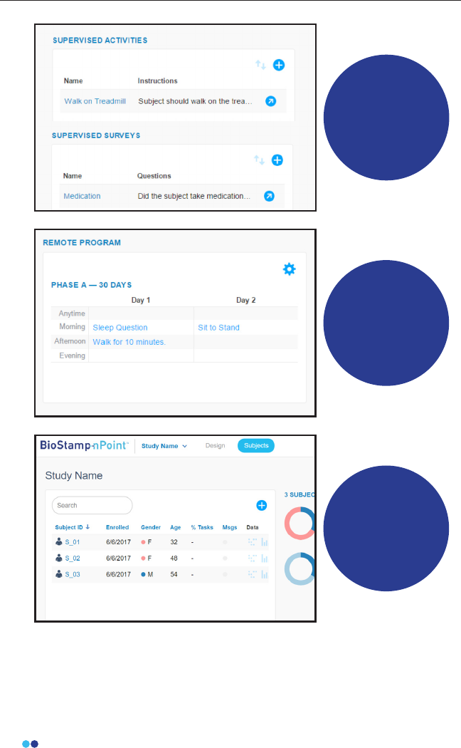
Add Prescribed
Activites
and Surveys
Design
Remote
Programs to
Guide Subjects
Through Study
Tasks
Add Subjects and
Subject Fields
29
BioStamp nPoint User Manual
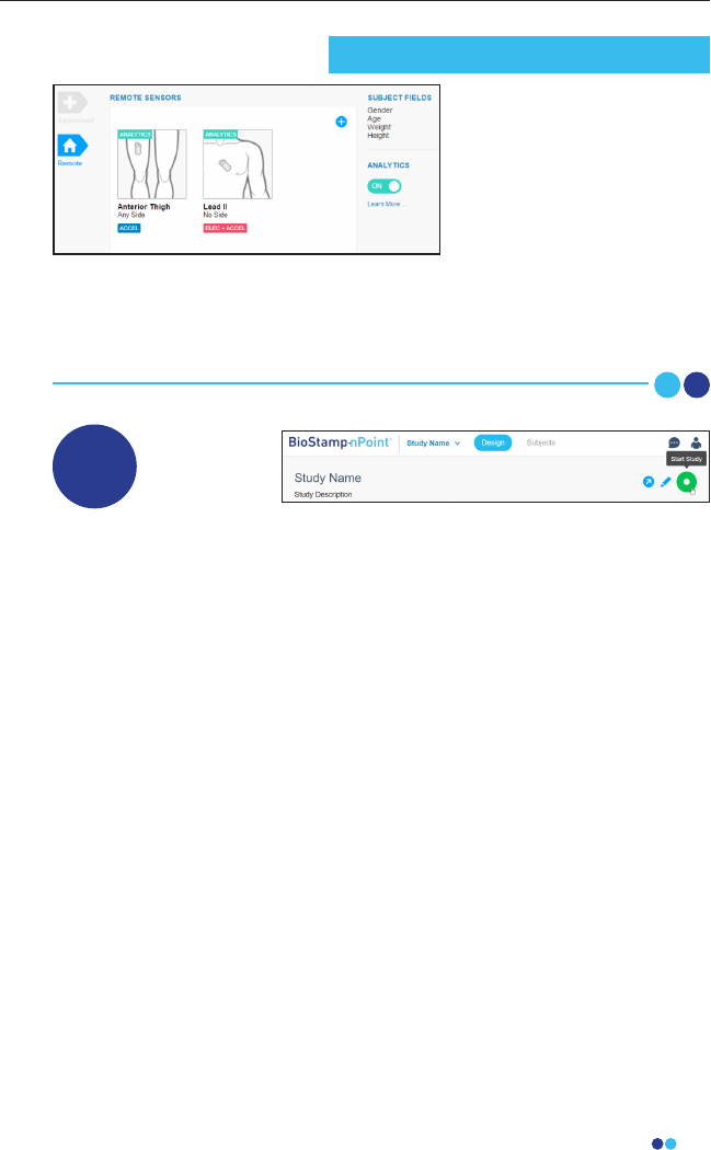
When your study is fully congured, select “start study” to lock
parameters. Your study is now in progress.
3Start Study
In the Remote environment,
you can also add Analytics
for daily reports of subject
activity, posture, sleep and
heart rate.
When analytics are
activated, two
pre-congured Sensors (anterior thigh with accel, Lead II with
electrodes + accel) will be added to the Sensors eld. These two Sensors
cannot be edited and are necessary for analytics reporting, but
additional Sensors can be added to the Remote Study conguration.
Remote Study Analytics
30
BioStamp nPoint User Manual
Run a Supervised Study
Investigators can design and run Supervised Studies to
leverage BioStamp nPoint in more traditional clinical
settings.
Activate Bluetooth and
connect to Wi-Fi on the
provided tablet.
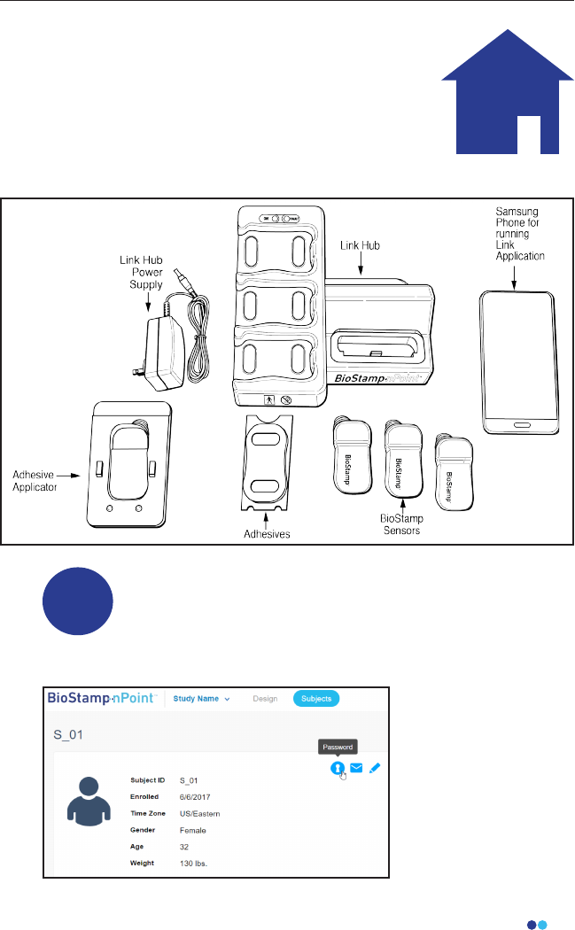
1Add Additional Subjects and Assign
Sensors with Investigator Application
Supervised Studies utilize the following components:
31
BioStamp nPoint User Manual
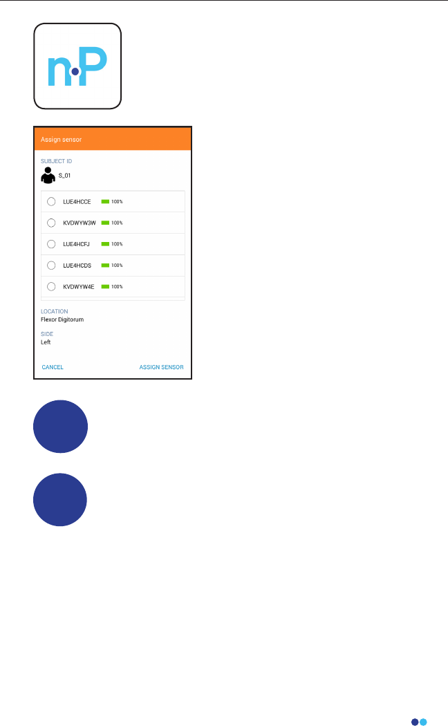
Open the Investigator App to run
studies in the clinic or lab.
Using the app, you can add
additional subjects to the study and
assign BioStamp Sensors to
subjects.
Apply Sensors to Subjects
Once Sensors have been assigned to study subjects, follow
the BioStamp Sensor application instructions (page 20) to
adhere adhesives and secure Sensor placement on the body.
2
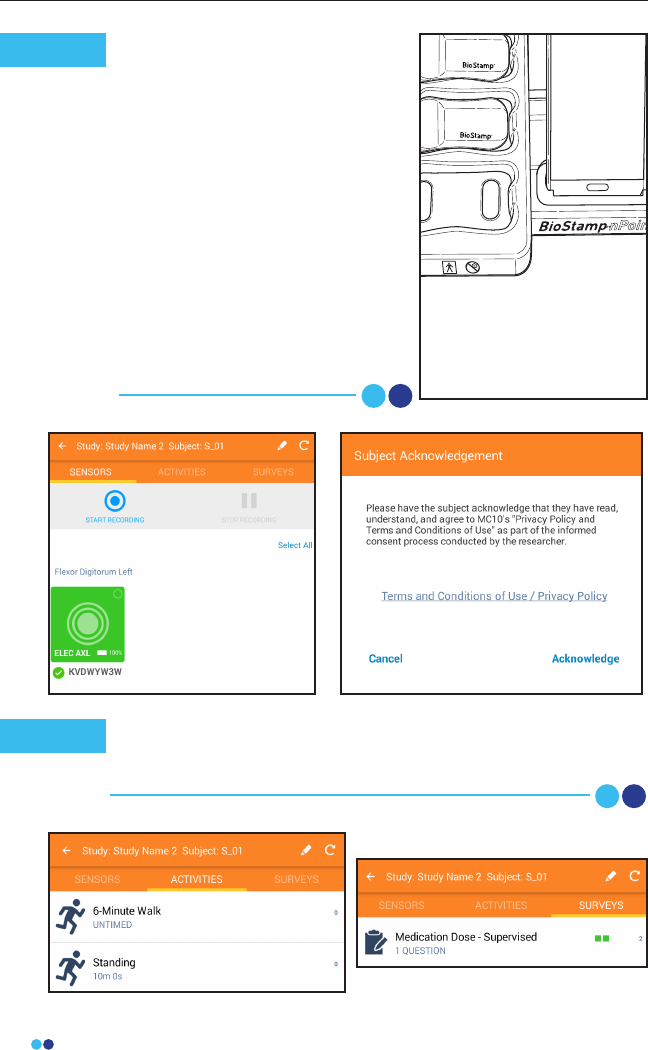
Run Study Using the Investigator Application
Use the Investigator App to activate Sensors, verify sensor
signal, start recording, time-stamp activities, and collect
survey responses.
3
32
BioStamp nPoint User Manual
0-3
When checking Sensor
biopotential signal quality at a
muscle location, you can use the
built-in Signal-to-Noise Ratio (SNR)
feature. Press “Relaxed” when the
subject is completely relaxing the
muscle. When the “Contracted”
button becomes available, have
the subject contract the targeted
muscle and hold the contraction.
Press the “Contracted” button until
the signal and noise voltage values
appear. The subject does not need
to continue contracting the
targeted muscle.
Note
Before beginning recording, you will need to review the
BioStamp nPoint Terms and Conditions of Use and Privacy
Policy with the patient and receive Subject Acknowledgement.
Note
33
BioStamp nPoint User Manual
Once an Activity or Survey has been completed, a green block
will appear to the right indicating the number of times that
Activity or Survey has been completed. Once an Activity or
Survey has been completed more than ten times, visualized
by ten green blocks, the number will increase for each further
repetition but the ten blocks will remain.
Note
Remove and Clean Sensors
Remove Sensors from subject after a maximum 24 hours of
wear. Dispose of adhesives, and clean Sensors for subsequent
use (Maintenance page 24).
5
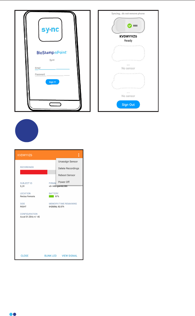
Synchronize Sensor Data
Synchronize data from the Sensors by rst placing the
Sensors on the Link Hub. Place the Sync Phone in the Link
Hub dock. Then log in to the Sync App with your
BioStamp nPoint credentials to begin syncing Sensor data to
the Investigator Portal.
6
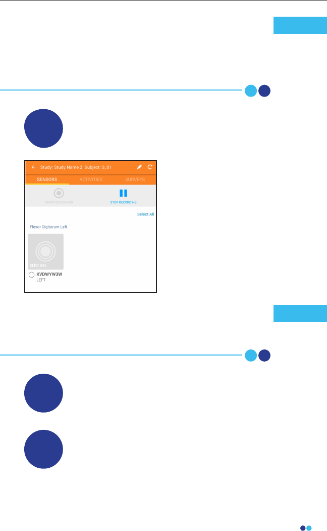
Stop Sensor Recording
4
Navigate to the Sensors tab on the
Investigator App, select the Sensors
that no longer need to record, and
press “stop recording.”
If a Sensor falls o while recording, press “stop recording,”
remove all Sensors, sync data, apply new adhesives and
re-apply Sensors, press “start recording,” and resume study
activities.
Note
34
BioStamp nPoint User Manual
Unassign and Power O Sensors
7
Once data has been synced, you
may unassign and power o Sensors
(for battery life preservation) in the
Sensors tab on the Investigator App.
35
BioStamp nPoint User Manual
Run a Remote Study
Investigators can design and run Remote Studies to col-
lect data outside of the clinic or lab. The BioStamp nPoint
Remote Kit contains all the tools necessary to gather
insights from a subject’s daily life or home environment.
Supervised Studies utilize the following components:
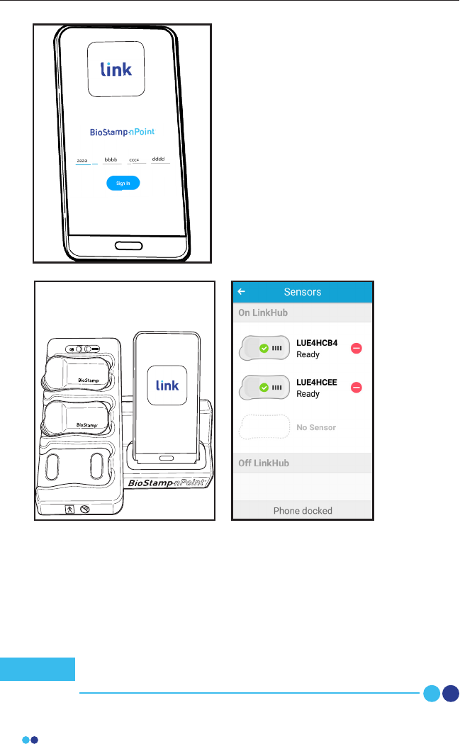
1
Assign BioStamp nPoint Remote Kits to Subjects
To active a subject’s account and assign BioStamp nPoint
take home components for a Remote Study, you will need
to input a key code in the Link App on their assigned Link
Phone.
To generate this key
code, open the
subject’s prole in the
Investigator Portal,
and press the Remote
Password lock icon. This
will generate a 16-letter
code.
36
BioStamp nPoint User Manual
0-3
Input this code into the subject’s Link
App to associate the app with the
subject’s study program and assign the
Link Phone to the subject.
This code will also be provided to the
subject for logging in and out of the
Link App.
Place the Link Phone into the Link Hub dock (that you plan to send
home with the subject) and follow the prompt to assign BioStamp
Sensors. Choose the Sensors and place them in the Sensor pockets on
the Link Hub. If assigning more than 3 Sensors, wait until the rst set
of 3 Sensors have been recognized by the Link App and then replace
with any additional Sensors you wish to assign. This can be repeated to
assign as many Sensors to the system as needed.
Once all Sensors have been recognized by the Link App, all
system components have been assigned to the subject.
Note
37
BioStamp nPoint User Manual
2
Train the Subject and Send Them Home with
BioStamp nPoint Remote Kit
Remote Kit components are designed for Remote operational
use by the subject. Train the subject on system use prior to
sending the subject home with their Remote Kit and Subject
IFU to initiate the study program.
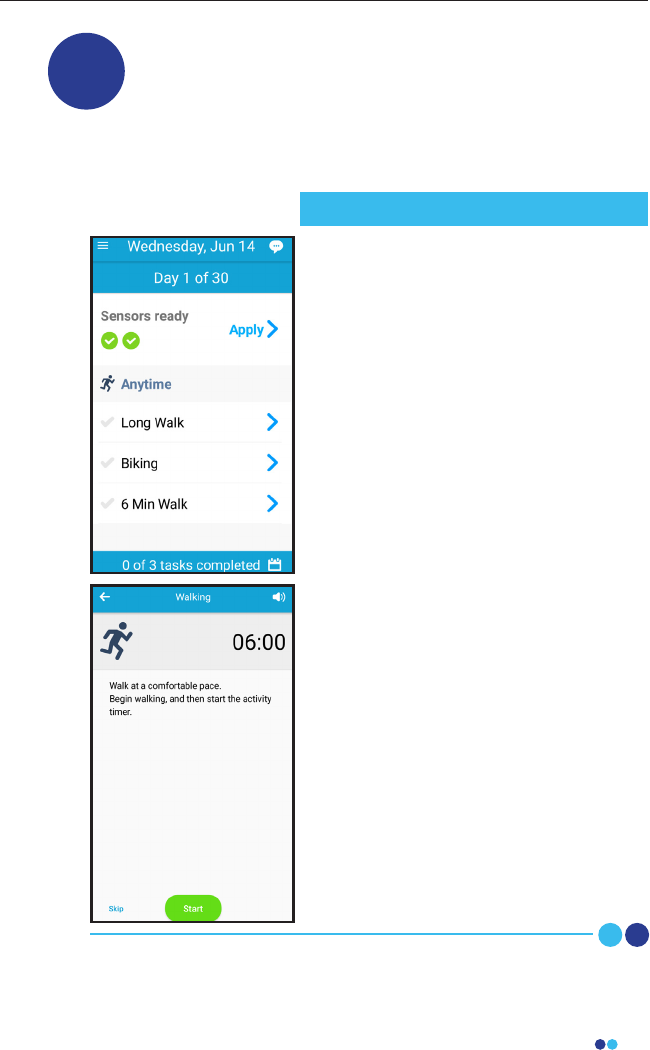
At home, subjects will set the Link Hub
on a at, stable surface, plug the
provided power supply into the back of
the Link Hub, and insert the wall adapter
plug end into a nearby outlet.
Subjects will then charge BioStamp
Sensors by placing them in the sensor
pockets on the Link Hub and will charge
and connect the Link Phone by plugging
into the phone stand in the Link Hub.
When the phone and Sensors are
charged, they will open the Link App and
follow instructions to apply Sensors
(including Sensor position check),
complete prescribed activities, and
answer survey questions.
At the time of Sensor removal, subjects
will follow instructions to remove, clean,
and recharge Sensors. When Sensors are
placed back on the Link Hub for
recharging, the collected data will be
sent to the Investigator Portal for i
nvestigator review.
Subjects will follow Link Hub instructions
until the end of the Remote Program,
and then return the Remote Kit to the
investigator.
Subject Study Procedure
38
BioStamp nPoint User Manual
Subject Assessment and Data Analysis
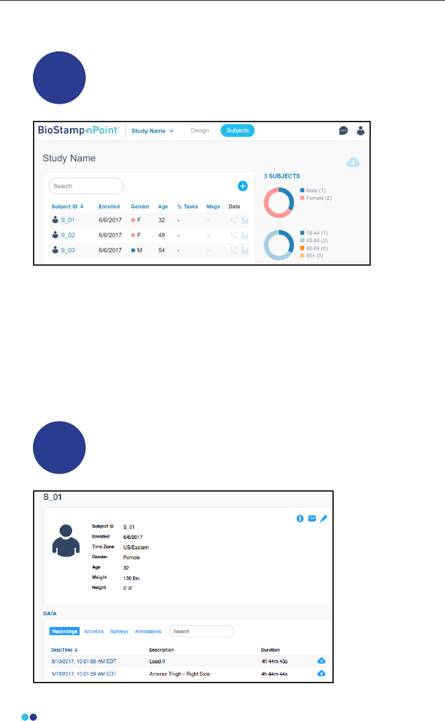
1Assess Subject Progress
Open the Investigator Portal and click on the Subjects page to nd the
list of subjects that have been enrolled and their Gender (if entered),
Age (if entered), Tasks Completed (%), and Data (linked to Raw Data and
Analytics, if applicable).
Investigators can send messages to subjects, as well as view messages
from subjects participating in Remote programs. Once a message from
a subject is viewed, it can be marked as “Read” to reset the Msgs ag on
the Subjects page.
View and Download Raw Data
Click on a subject’s ID in the Investigator Portal Subjects page
to access their data.
2
39
BioStamp nPoint User Manual
Under the Data section of the subject’s prole, each recording is listed
by Sensor. Click on the date and time of the recording for a raw signal
visualization.
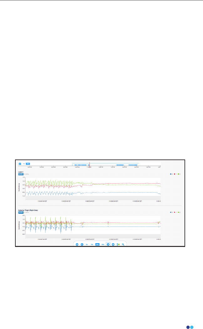
Plots of raw data versus time can be visualized on the dashboard for
each sensor signal and can be navigated to a specic timestamp,
activity, survey, or annotation. Navigation tools on the dashboard
facilitate jumping to the beginning or end of a recordings, as well as
specic points of interest. The calendar option allows investigators
to visualize the dates when subjects have recordings. The timescales
are dynamic (toggle between 1 hour and 12 hour view) and resolution
options includes 5, 15, 30, and 60 second windowing intervals - as well
as auto-scaling.
Activities and surveys are displayed on the timescale alongside the raw
data and metrics (when enabled) so investigators can easily analyze
time bounds of interest. In addition, the annotation feature in the raw
data view allows investigators to contextualize the raw signal with
custom notes, just by clicking on the plot. These manual annotations
can be a single point or cover a time range and are exported with the
other events in the subject’s csv le.
Click on the download icon to download the CSV le of Sensor data
from each recording.
All Activities, Surveys, and Annotations data can be downloaded as a
CSV le by clicking on the single download icon in the corner of either
of the Activities, Surveys, or Annotations windows.
Raw data can also be accessed by clicking on the Raw Data icon located
in the top right corner of the Subjects page of the Investigator Portal.
40
BioStamp nPoint User Manual
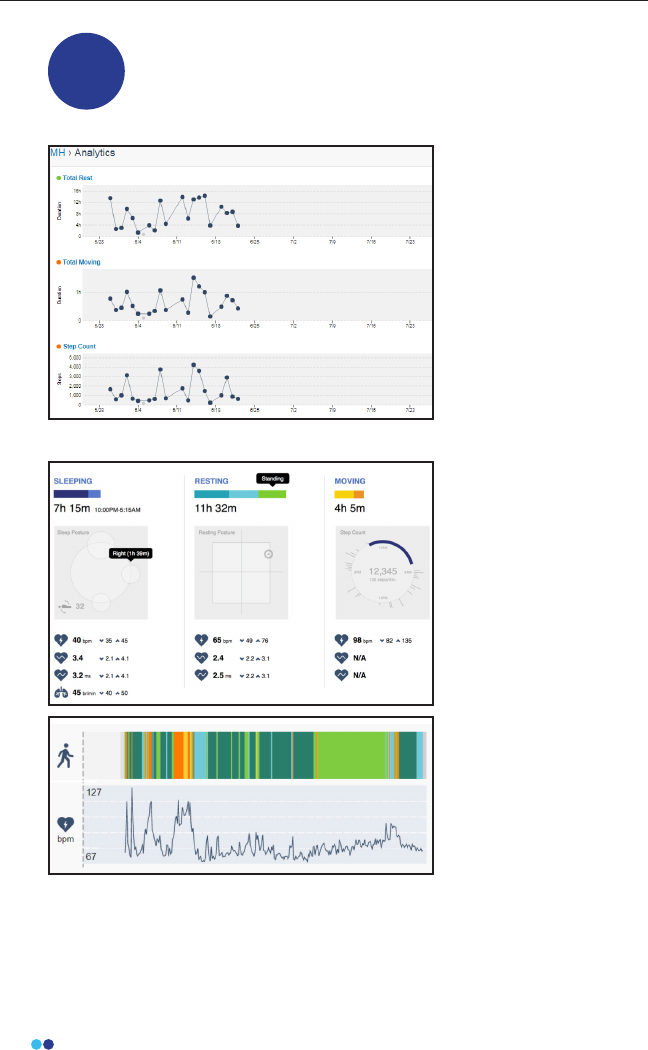
Access the Analytics Dashboard (Remote Studies Only)
For a Remote study, you can click on the Analytics Icon in the
subject prole to view the analytics reports for that subject.
3
The Analytics icon
brings you to a
cumulative view of the
43 computed metrics
over time, with a daily
resolution. This view
is customizable by
selecting the settings
icon in top right corner.
Investigators can select
which metrics to display
and can also arrange the
order.
Investigators can
navigate to the daily
subject metric
dashboard by
selecting one of the
metrics on the timeline.
Daily metrics are
reported for 3 states:
Sleeping, Resting, and
Moving. Average,
minimum, and
maximum heart rate
and heart rate variability
values are reported for
each of the 3 states.
The sleeping report
shows sleep duration
and sleep posture
visualization. The resting report shows total resting duration (sitting,
standing, lying) and posture visualization. The moving report shows
total moving time (walking, other), cumulative number of steps when
activity is classied as walking, step cadence (steps/min), and a visual-
41
BioStamp nPoint User Manual
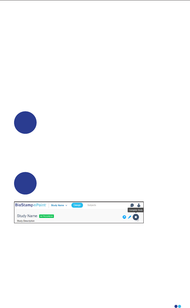
Complete Study
5
Once all subject data for a study has been collected, click on the
Complete Study icon in the Design Study page of the Investigator
Portal. After the Complete Study icon is clicked, new subjects cannot be
added or edited and new data can no longer be collected. A label will
appear next to the study name to indicate the study has been
completed.
ization of activity across 4 time periods.
Beneath the reports you will nd the detailed outputs displayed across
the time scale, which includes the activity class, respiration rate when
activity is classied as sleeping, heart rate, and heart rate variability. This
plot is dynamic and can be zoomed to a 1 hour view. Investigators can
easily navigate to annotations and raw data from the daily metrics view.
Return to the Subjects page and click the Export Analytics icon to
download all analytics from the study. The analytics export le contains
all the subject metadata and metric outputs for the entire study. It can
be requested while a study is in progress, and will be automatically
generated upon completion of a study. Each subject will have a single
csv le for the cumulative metrics (daily aggregates), as well as a le for
each day that metrics were computed.
Access the API for Specic Downloads
Investigators can access the MC10 API through the API
Docs link on the footer of the Investigator Portal or https://
mc10cloud.com/apidoc/. This is an interactive API tool that
enables ecient data queries through the REST API. The
available study endpoints include studies, subjects,
recordings, programs, activities, annotations, messages,
equipment, and metrics.
4

Troubleshooting
and Manufacturer

43
BioStamp nPoint User Manual
Software
If the Investigator App, Sync App, or Link App display any errors or become
unresponsive, rst check to ensure that Bluetooth and Wi-Fi are connected. If
both are connected, turn each of them o and on again.
If the errors persist, force quit the MC10 application and restart the device.
Contact the responsible organization if issues continue to occur.
Hardware
If the BioStamp Sensor or Link Hub indicates a failure, stop using the product
and contact the responsible organization or manufacturer.
For support, service in setting up or using, maintenance, return of expired
system components for proper decommissioning, or further information on
this Medical Electrical (ME) System Equipment contact the manufacturer:
Troubleshooting
Manufacturer
MC10, Inc.
10 Maguire Rd., Building 3, Floor 1, Lexington, MA 02421, USA
Phone: +1 (857) 214-5600
Fax: +1 (781) 538-6641
Web: www.mc10inc.com
Email: BioStampnPoint@mc10inc.com
FAQs
To review frequently asked questions, visit https://www.mc10inc.com/faq

Appendix A

45
BioStamp nPoint User Manual
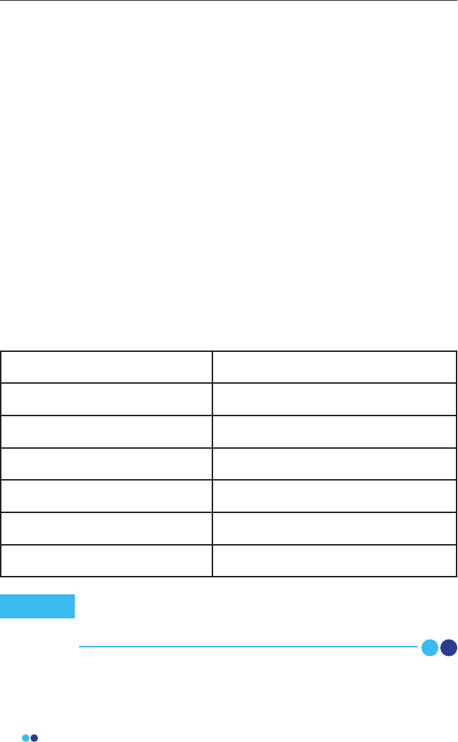
BioStamp nPoint Platform Components
Documentation
Instructions for Use
Subject Instructions for Use for Re-
mote Studies
Core Components
and Accessories
Link Hub and Power Supply BRSD01;
BSPS01
(SL Power
Electronics
Model ME-
20A0900B02)
BioStamp Sensors BRCS02
Adhesive Stickers BRCA02
Adhesive Applicator BRCA05
Investigator Web Portal (MDDS or
MC10 Cloud)
Supervised
Components
Tablet with Investigator Application
and Tablet Charger
BRCT02
Mobile Phone with Sync Application BRCP02
Remote
Components
Mobile Phone with Link Application BRCP01
Link Hub 24 months from date of original manufacture
Expiration date is indicated on the device label
Tablet 24 months from date of original manufacture
Expiration date is indicated on the device label
Sync Phone 24 months from date of original manufacture
Expiration date is indicated on the device label
Link Phone 24 months from date of original manufacture
Expiration date is indicated on the device label
BioStamp Sensor 19 months from date of original manufacture
Unopened
Adhesive
13 months from date of original manufacture
Expiration date is indicated on the adhesive packaging
BioStamp nPoint Component Service Life
BioStamp nPoint includes the following components:

46
BioStamp nPoint User Manual
Technical Specications
BioStamp Technical Specications
Size
Dimensions 7.1 x 3.4 x 0.5 cm (LxWxH max)
Weight 8.7 grams
Material Low durometer silicone
Sensors
Accelerometer
Range ±2-16g0 ± 10%
Bit Depth 16
Precision 0.6 mg
Sample Rate 15.625-250 Hz ± 15%
Zero-g Output ±60 mg
Gyroscope
Range ±250-2000 °/s ± 10%
Bit Depth 16
Resolution 0.07 °/s
Sample Rate 15.625-250 Hz ± 2%
Zero Rate Output ±5 °/s
1-lead Analog Front End
Range ±300 mV
Resolution 10 mV
Bit Depth 16
Sampling Rate 125-1000 Hz ± 2%

47
BioStamp nPoint User Manual
BioStamp Recording Modes
Sensor Sample Rates
Available
Dynamic Ranges
Available
Accelerometer 15,625, 31.25, 62.5 125,
250 Hz
+/- 2G, +/- 4G, +/- 8G,
+/- 16G
Gyroscope + Acceler-
ometer
15,625, 31.25, 62.5 125,
250 Hz
Gyroscope Range
+/- 250°/s, +/- 500°/s,
+/- 1000°/s, +/- 2000°/s
Accelerometer Range
+/- 2G, +/- 4G, +/- 8G,
+/- 16G
AFE 125, 250, 500, 1000 Hz +/- 300 mVDC
Accelerometer + AFE
31.25 Hz (accelerome-
ter) and 250, 500, 1000
Hz (AFE)
+/- 2G, +/- 4G, +/- 8G,
+/- 16G (accelerome-
ter) and +/- 300 mVDC
(AFE)
Adhesive Technical Specications
Size
Dimensions 70 x 38 x 1.4 mm (L x W x H)
Weight 2.2 grams
Material Biocompatible medical foam, adhe-
sives, and hydrogel
48
BioStamp nPoint User Manual
Link Hub and BioStamp Sensor Frequency and Transmission
Specications
Frequency band of reception 2400-2500 MHz
Bandwidth of reception 1 MHz
Frequency band of transmission 2400-2500 MHz
Transmission type IEEE 802.15.1 direct sequence spread
spectrum (BLE), 0.015 mW EIRP
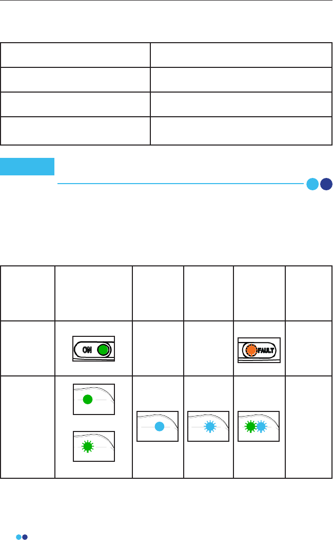
LED Indicator Messages
Hardware LED Status Indicator Table
For any system or component failures including power failures (indicated by
lack of any lights), please contact the provider for a replacement patient kit.
There is no alarm system.
Power On /
Ready For Use Charging Ready to
Apply
Warning/
Failure
Power
O
Link Hub ----- ----- No LEDs
BioStamp
Sensor
(on Link Hub)
(o Link Hub)
No LEDs
No recurring testing is needed during the expected service life.
Link Hub IEC 60127-1 internal fuse rated as F 2A, 63VDC.
Note

49
BioStamp nPoint User Manual
EMC Declaration and Guidance
Guidance and Manufacturer’s Declaration – Electromagnetic Emissions
The BioStamp nPoint system is intended for use in the electromagnetic
environment specied below. The customer or the user of the BioStamp
nPoint system should assure that it is used in such an environment.
Emissions Tests Compliance Electromagnetic Environment -
Guidance
RF Emissions
CISPR 11
Group 1
The BioStamp nPoint use RF
energy only for system
communication functions.
Therefore it’s RF emissions are
very low and are not likely to
cause any interference in nearby
electronic equipment.
RF Emissions
CISPR 11
Class B The BioStamp nPoint system is
suitable for use in all
establishments, including
domestic establishments and
those directly connected to the
public low-voltage power supply
network that supplies buildings
used for domestic purposes.
Harmonic Emissions
EN61000-3-2
Class A
Voltage Fluctuations/
Flicker Emissions
EN61000-3-3
Per Section 5 of
the Standard

50
BioStamp nPoint User Manual
Guidance and Manufacturer’s Declaration – Electromagnetic Immunity
The BioStamp nPoint system is intended for use in the electromagnetic
environment specied below. The customer or the user of the BioStamp
nPoint system should assure that it is used in such an environment.
Immunity Test IEC 60601 Test
Level
Compliance
Level
Electromagnetic Envi-
ronment - Guidance
Electrostatic
Discharge (ESD)
EN61000-4-2
+/-15 kV Air
Discharge
+/-8 kV Contact
Discharge, VCP,
HCP
+/-15 kV
+/-8 kV
Floor should be wood,
concrete or
ceramic tile. If oors
are covered with
synthetic material,
the relative humidity
should be at least 30%.
Radiated
Electromagnetic
Fields
EN61000-4-3
10 V/m, 80-2700
MHz at 80%, 1
kHz AM
Modulation
10 V/m Portable RF
communications
equipment (including
peripherals such as
antenna cables and
external antennas),
microwave ovens,
cordless phones, Wi-Fi
devices should be used
no closer than 30 cm
(12 inches) to any part
of BioStamp nPoint
system, including
cables specied by the
manufacturer,
otherwise,
degradation of the
performance of this
equipment could
result.
Radiated
Electromagnetic
and Proximity
Fields
EN610004-3
9-28 V/m, RF
Wireless
Communication
Fields on Spot
Frequencies from
Table 9 at 50%,
Square Wave
Modulation
9-28 V/m
Conducted
EN61000-4-6
6 Vrms on ISM
and Amateur
Bands
3 Vrms, 0.15-80
MHz, AC Mains
3 Vrms, 0.15-80
MHz, SIP/SOP
Ports
6 Vrms
3 Vrms
3 Vrms

51
BioStamp nPoint User Manual
Immunity Test IEC 60601 Test
Level
Compliance
Level
Electromagnetic Envi-
ronment - Guidance
Power Frequen-
cy Magnetic
Field
EN61000-4-8
30 A/m at 50 or
60 Hz 30 A/m
Power frequency
magnetic elds should
be at levels
characteristic of a
typical location in a
typical domestic
environment.
Electrical machinery
should be used no
closer than 30 cm (12
inches) to any part
of BioStamp nPoint
system, including
cables specied by the
manufacturer,
otherwise, degradation
of the performance of
this equipment could
result.
Electrical Fast
Transient/ Burst
EN610004-4
+/-2 kV on AC
Mains
N/A on SIP/SOP
Ports
+/-2 kV
N/A
Mains power should
be that of a typical do-
mestic environment
Surge
EN61000-4-5
+/-2 kV Common
Mode
+/-1 kV Dieren-
tial Mode
N/A on SIP/SOP
Ports
+/-2 kV
+/-1 kV
N/A

52
BioStamp nPoint User ManualBioStamp nPoint User Manual
Immunity Test IEC 60601 Test
Level
Compliance
Level
Electromagnetic Envi-
ronment - Guidance
Voltage Dips,
Short Inter-
ruptions and
Voltage Varia-
tions on Power
Supply
EN61000-4-11
0%, 0.5 Cycles
0%, 1 Cycle
70%, 25/30
Cycles
0%, 250/300
Cycles
0%
0%
<70%
0%
Mains power should
be that of a typical do-
mestic environment

53
BioStamp nPoint User Manual
Appendix B
54
BioStamp nPoint User Manual
Programmable Electrical Medical System (PEMS) connection to an
IT-Network
Data is transferred continuously among components during normal system
operation. Raw (unprocessed) sensor data is transferred wirelessly from the
patch to the mobile through Bluetooth LE. When network connectivity is
available, sensor data is transferred from the mobile to the cloud. Once the
cloud conrms receipt of the sensor data, the patch’s on-board ash memory
may be cleared for subsequent recording.
Implemented Protocols
BLE, USB, and HTTP standard protocols are implemented between the PEMS
and the IT-network. These protocols encompass and incorporate the
required characteristics of the IT-network incorporating the Portable
Emissions Measurement System (PEMS), the required conguration of the
IT-network incorporating the PEMS, and the technical specications of the
network connection of the PEMS including security specications.
BioStamp Sensor to Link Hub BLE/ESB
BioStamp Sensor to Tablet BLE
BioStamp Sensor to Phone BLE
Link Hub to Link App USB, Android Open Accessory
Portal to Cloud public internet, HTTPS
Investigator App/Tablet to Cloud WiFi, public internet, HTTPS
Link App/Phone to cloud WiFi or cellular, public internet, HTTPS
Information Flow
The intended information ow between the PEMS, the IT-network and other
devices on the IT-Network, and the intended routing through the IT-network:
This can include aspects of eectiveness and data and system
security as related to basic safety and essential performance
(see also Clause H.6 and IEC 80001-1:2010).
Note

55
BioStamp nPoint User Manual
Sensor to Mobile Communication
Data stored on the patch’s on-board memory is secured through a
proprietary bit packing and memory block allocation scheme.
Communication to the patch is only enabled through custom-built
mobile applications. All MC10 applications require an authorized user
login using valid credentials. During operation, each patch is uniquely
assigned to a subject, in a specied conguration mode which includes
the sensor modality and body location. Patch to mobile and mobile
to patch communication is secured through a custom cmd-ctrl-data
protocol and compression algorithm that runs across the Bluetooth LE
protocol packets.
Mobile to MC10 Cloud Communication
Application data is encrypted (256-bit AES) and stored on the local
SQLite database on the mobile.
Upon network connectivity, data is transmitted between the mobile and
cloud using HTTPS protocols, which requires authentication with valid
credentials. This encrypted connection protects the privacy and
integrity of the exchanged data.
All cloud API interactions are logged with the following attributes:
• Authenticated user taking the action
• Source IP address of user
• Time of interaction
• Resources viewed or action taken
MC10’s cloud network and systems are protected with standard security
practices (rewalls, VPC, access restrictions, and automated
conguration management). Access to the data is restricted at multiple
levels and is protected by MC10’s Access Control Lists (ACLs) framework.
ACLs restrict resource availability to approved users and groups. Each
user belongs to at least one group and is assigned one or more roles
within their respective group. Roles dene which resources and what
actions are available to a user in a given group.
Hazardous Situations
Potential hazardous situations resulting from a failure of the IT-NETWORK to
provide the characteristics required to meet the purpose of the PEMS
connection to the IT-NETWORK:
• Investigator Portal, Investigator App, and/or Link App cannot connect to
public internet;

56
BioStamp nPoint User Manual
• Investigator Portal, Investigator App, and/or Link App can’t connect to
MC10 MDDS;
• Erroneous data transfer between Investigator Portal, Investigator App,
and/or Link App and MC10 Cloud;
• Data corruption on MC10 Cloud due to foreseeable misuse (i.e. hacking);
• Investigator App or Link App can’t congure/control BioStamp Sensor;
• Link Hub cannot control/download BioStamp Sensor;
• Erroneous data transfer between BioStamp Sensor and Link Hub;
• Link App cannot control/download smart charger;
• Erroneous data transfer between Link App and Link Hub;
• Data corruption on smart charger due to foreseeable misuse (i.e. hack-
ing).
Connection of the system to an IT-network that includes other equipment
could result in previously unidentied risks to patients, operators, or third
parties. The responsible organization should identify, analyze, evaluate and
control these risks. Subsequent changes to the IT-network could introduce
new risks and require additional analysis. Changes to the IT-network include:
• changes in the IT-network conguration;
• connection of additional items to the IT-network;
• disconnecting items from the IT-network;
• update of equipment connected to the IT-network;
• upgrade of equipment connected to the IT-network.