MEAZON ELECTRONIC SYSTEMS DR3PA DINRAIL 3-PHASE ADVANCED User Manual
MEAZON ELECTRONIC SYSTEMS SA DINRAIL 3-PHASE ADVANCED
User Manual
MEAZON DINRAIL 3-PHASE ADVANCED
Installation Guide

1
MEAZON ELECTRONIC SYSTEMS S.A.
N.E.O PATRON ATHINON 57, 26442, PATRA, Greece
Greeceinfo@meazon.com support@meazon.com +30 2610 430000
www.meazon.com
Table of Contents
Features & Technical Specifications ...................................................................................................................... 2
General Installation instructions ........................................................................................................................... 5
Installation in a three-phase panel ....................................................................................................................... 6
CTs installation .............................................................................................................................................. 6
Power lines L1 L2 L3 installation ................................................................................................................... 6
Installation in a single phase Panel ....................................................................................................................... 7
Installation for loads up to 2400A ......................................................................................................................... 8
External Power Relay installation examples ......................................................................................................... 9
3-phase Power Relay installation .................................................................................................................. 9
1-phase Power Relay installation ................................................................................................................ 10
Indication contact installation examples ............................................................................................................ 11
Brief description .......................................................................................................................................... 11
Night tariff indication example ................................................................................................................... 11
Miniature circuit breaker (MCB) indication example.................................................................................. 11
About MEAZON ................................................................................................................................................... 12
2
MEAZON ELECTRONIC SYSTEMS S.A.
N.E.O PATRON ATHINON 57, 26442, PATRA, Greece
Greeceinfo@meazon.com support@meazon.com +30 2610 430000
www.meazon.com
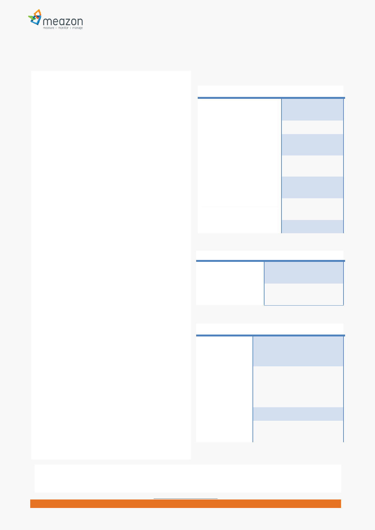
Features & Technical Specifications
Communication Specifications
Communication protocol ZigBee Mesh
Network
Frequency band 2.4GHz
Simultaneous operation of
multiple metering systems
Yes
Data communication interval 1 second (default 5
minutes)
Response in case of
communication loss
Yes (Rerouting
through Ζigbee)
Security - Communication
Encryption
Yes (AES encryption
128 bits)
Data Storage Up to 25 days
Electrical Specifications
Operating Voltage (*) /
Frequency
100-285 Vac / 45-
65 Hz
Power loss Response Automatic resumption of
operation after power loss
Electrical measurements
Electrical
parameters
measured
Irms, Vrms, Active Power & Energy,
Reactive Power & Energy
Ranges of
measured
parameters
Voltage: 0 to 285 Vac between
phase and Neutral (**)
Current: up to 2400 Amps (CT
model depended)
Tolerance +10% of nominal load (Iον)
Accuracy of
measurements
<1% of reading measurement
error (***)
MEAZON has developed “DINRAIL 3-PHASE
ADVANCED”, a 3-Phase electricity meter capable of
remote monitoring and controllingenergy
consumption of a household and/or an industrial
building.
It is a wireless metering system based on ZigBee
Mesh network technology, featuring a unique design
that combines low cost and high accuracy
measurements.
Every metering device on the ZigBee network is
associated with a ZigBee gateway. The role of the
gateway is to periodically collect all measurements,
gathered by the devices, in order to forward them to
the MEAZON Cloud for storage and further analysis.
MEAZON Cloud gives users the ability to monitor the
current energy consumption, set alarm rules, control
their devices (on/off switching) and schedule them
to operate in a desired pattern.
MEAZON DINRAIL 3-PHASE ADVANCED is a rail-type
device with small size (1.5 din), can be easily installed
and is capable of monitoring, measurement logging
and controlling:
up to three separate power lines / loads
a three phased load
an entire electrical panel (either single-phase,
dual-phase or three-phase)
It comes with three current transformers so as to
measure any electrical load without limitations.
It can drive a cold junction where a Power Relay
could potentially be connected and control (on/off)
the power supply to a load.
The Relays control logic can be externally driven
using On/Off commands or internally using MEAZON
scheduling.
Finally, MEAZON DINRAIL 3-PHASE ADVANCED is
equipped with a general purpose indication contact,
operating under “Neutral detection” logic, which can
be used as an extra useful information input to your
system.
(*) Make sure your purchased DINRAIL 3-PHASE ADVANCED meets your appliances Voltage
(**) At least one of the measured phases must have models nominal Voltage
(***) Accuracy refers to Electric Power
Measurements
3
MEAZON ELECTRONIC SYSTEMS S.A.
N.E.O PATRON ATHINON 57, 26442, PATRA, Greece
Greeceinfo@meazon.com support@meazon.com +30 2610 430000
www.meazon.com
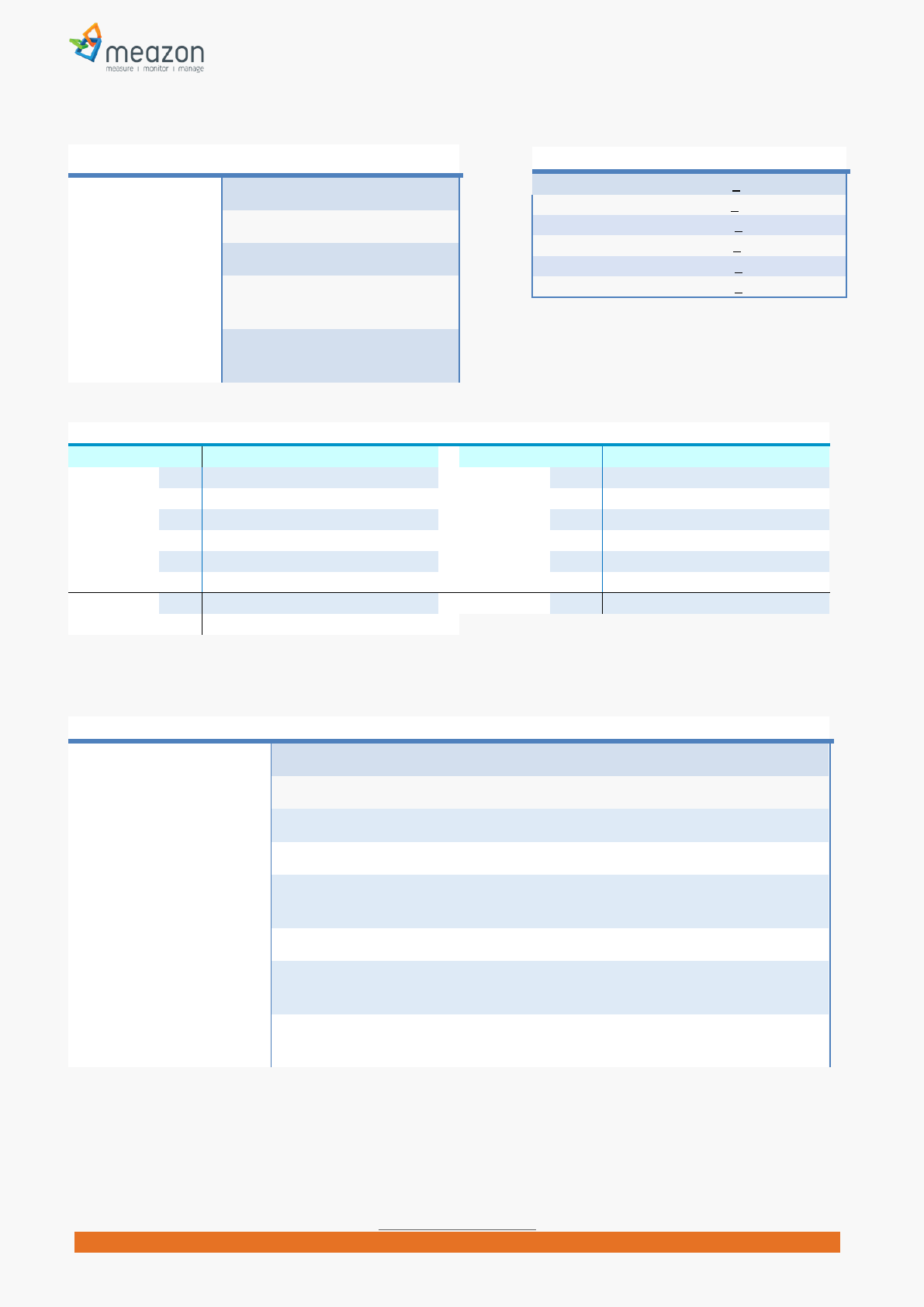
Mechanical and Environmental Specifications
Power Consumption 5VA
Dimensions (WxHxD) 27.8 x 80.0 x 58.3 in mm
Mass 0.085 Kg
Supply wiring
requirements
16 or 18AWG Solid/ Stranded,
torque 0.6Nm
Operating
Environment
Temperature: -20°C to 50°C
Relative Humidity: 10% to 90% RH
Current Transformers (CT) provided
CT 5Α, accuracy +1%
CT 63Α, accuracy+1%
CT 125Α, accuracy+1%
CT 250Α,accuracy+1%
CT 400A, accuracy +1%
CT 600A, accuracy +1%
Device Status based on led indications L1-LED1 / L2-LED2
LED1On Relay Switch On
LED1 Off Relay Switch Off
LED1Slow Blinking LED2 Off Idle state, not associated with a network, waits for Man/Machine interaction
LED1 Fast Blinking LED2 Off Beacon state, not associated with a network, in “ready to join” mode
LED1 On/Off
LED2 Fast Blinking
Normal operation, network associated, collecting measurements, Relay Switch On or
Off
Both LEDS Off Device is not operating
Both LEDS Blinking in
different frequency
Identifying state, network associated, collecting measurements, Relay Switch On or
Off
Both LEDS Blinking at the
same time
Operating error, device needs restart
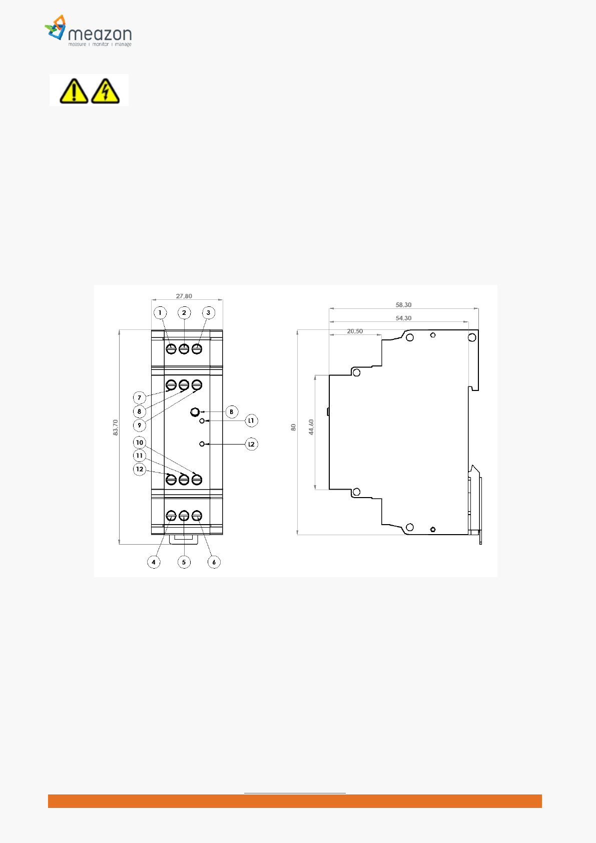
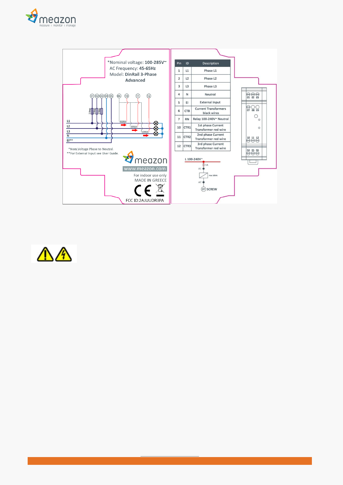
Electrical contacts
Connector Id Description Connector Id Description
1 L1 Phase L1 7 RN Power Relay 100~240Vac Neutral
2 L2 Phase L2 8 - NO Connect
3 L3 Phase L3 9 - NO Connect
4 N Neutral 10 CTR1 Current Transformer 1 Red Wire
5 NT Night Tariff 11 CTR2 Current Transformer 2 Red Wire
6 CTB Current Transformers Black Wires 12 CTR3 Current Transformer 3 Red Wire
LED1 L1 Relay On/Off BUTTON B Man/Machine interface Button
LED2 L2 Network status
4
MEAZON ELECTRONIC SYSTEMS S.A.
N.E.O PATRON ATHINON 57, 26442, PATRA, Greece
Greeceinfo@meazon.com support@meazon.com +30 2610 430000
www.meazon.com
Safety Information
Use this product only in the manner described in this manual. If the equipment is used in a manner not
specified by the manufacturer, the protection provided by the equipment may be impaired.
Product may be cleaned with a clean soft towel. Do not use liquids to clean.
Product is not water resistant. If the unit gets wet, do not touch it. Power off and allow it to dry thoroughly
before further operation.
Do not disassemble the product. There are no spare parts for this, it is not repairable. If physical damage to
the product occurs, do not use. Replace with a new one.
MEAZON DINRAIL 3-PHASE ADVANCED Diagram
5
MEAZON ELECTRONIC SYSTEMS S.A.
N.E.O PATRON ATHINON 57, 26442, PATRA, Greece
Greeceinfo@meazon.com support@meazon.com +30 2610 430000
www.meazon.com
General Installation instructions
INSTALLATION REQUIREMENTS
The instructions provided below, should be performed only by licensed electricians. Installation from non-
qualified individuals may lead to electrocution or heavy damage to the devices.
Wiring requirements: 16 or 18AWG Solid/ Stranded, torque 0.6Nm.
Make sure that the maximum amperage to be measured does not exceed the maximum value the provided
MEAZON DINRAIL 3-PHASE ADVANCED can measure.
MEAZON DINRAIL 3-PHASE ADVANCED must be protected with a 2A circuit breaker (3 pieces for 3-phase
electrical panels, 1 piece for single-phase electrical panels).
1) Locate the main electrical panel.
2) Turn the power off for safety reasons.
3) Locate the current conductors to be measured. Current transformers will be added at those conductors
WARNING! Current conductors should be between the electrical fuse and the circuit breaker (in case of
metering electrical loads separately), or between protection relay and electrical fuse (in case of measuring
total consumption).
4) Check inside the electrical panel for the optimal location to place the MEAZON DINRAIL 3-PHASE
ADVANCED as well as the 2A protective circuit breaker.

6
MEAZON ELECTRONIC SYSTEMS S.A.
N.E.O PATRON ATHINON 57, 26442, PATRA, Greece
Greeceinfo@meazon.com support@meazon.com +30 2610 430000
www.meazon.com
5) Place the protective circuit breaker at the rail.
6) Place the DINRAIL having the protection clip downwards and lock it at the rail of the electrical panel
In this installation guide DINRAIL 3-PHASE ADVANCED will be called DINRAIL for brevity reasons.
Installation in a three-phase panel
CTs installation
Connect each of the three Current Transformer’s
outputs (black wire) to contact 6 (CTB) of the
DINRAIL.
Connect each of the three Current Transformer’s
inputs (red wire) to contact 10 (CTR1), 11 (CRT2)
and 12(CRT3) of the DINRAIL respectively.
Locate the current conductors to be measured
starting from phase L1 and pass it through the coil
of the CT (current transformer) by opening the
coil of CT.
Close the CTs coil again. The red wire of this CT must be connected to contact 10 (CTR1) of the DINRAIL.
WARNING! Make sure the direction of the arrow illustrated at the CT
terminals to the load. Reconnect the current conductor.
Repeat the process for the other two phases (L2, L3).
Power lines L1 L2 L3 installation
Power the 2A protective circuit breakers from the main circuit
breakers of the electrical panel
Connect the output of each of the above circuit breakers with the
terminal 1(L1), terminal 2(L2) and terminal 3(L3) respectively of the DINRAIL.
WARNING! Make sure that the sequence of phases 1, 2 and 3 of the DINRAIL
is strictly L1, L2 and L3, otherwise measurements will be incorrect.
Connect the neutral conductor of the electrical panel to contact 4(N) of the
DINRAIL.
Check the entire procedure again before completing the installation
(sequence of the phases of the inputs of the DINRAIL, sequence of the
Current Transformers’ connection, direction of the arrow of each CT).
7
MEAZON ELECTRONIC SYSTEMS S.A.
N.E.O PATRON ATHINON 57, 26442, PATRA, Greece
Greeceinfo@meazon.com support@meazon.com +30 2610 430000
www.meazon.com
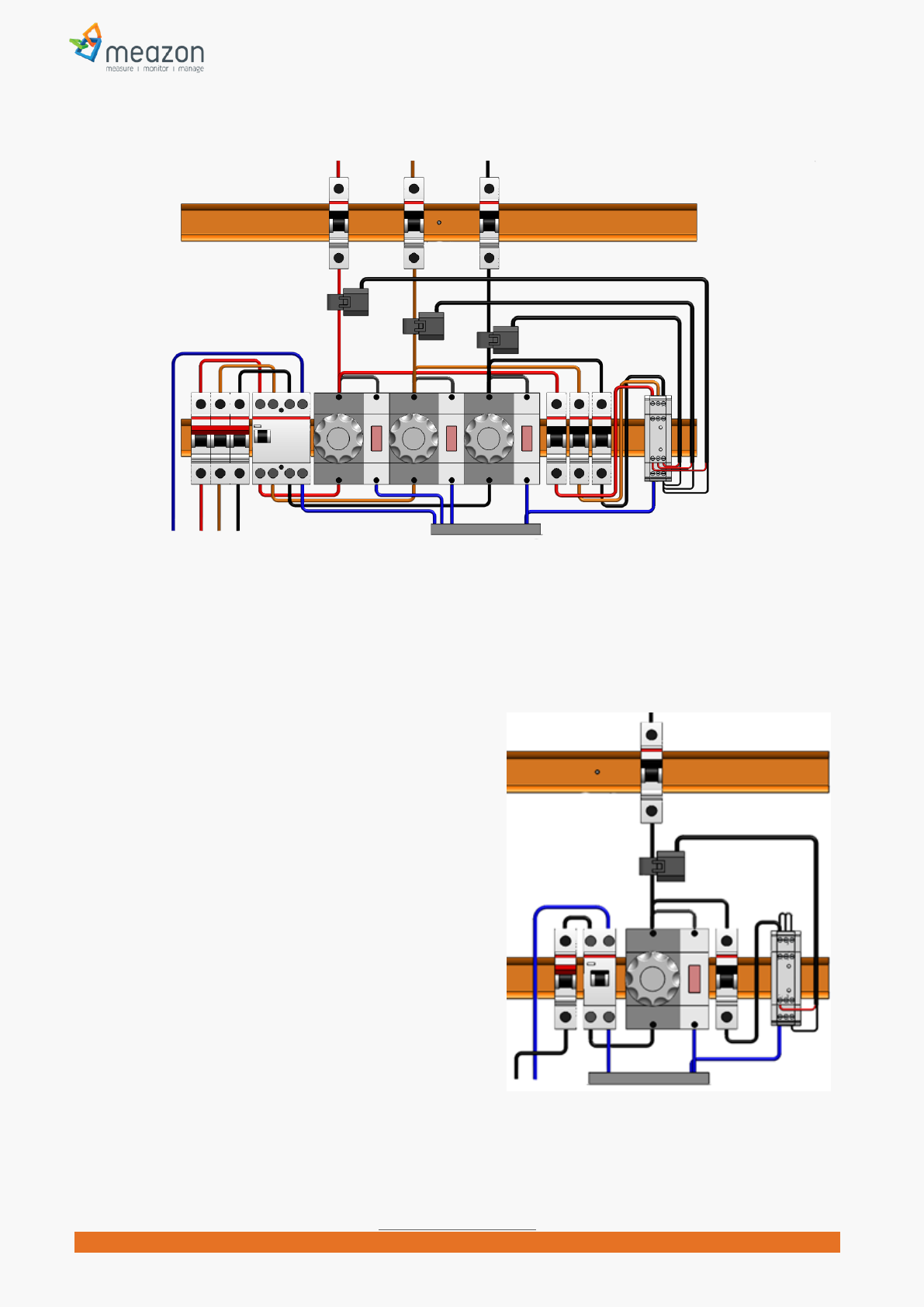
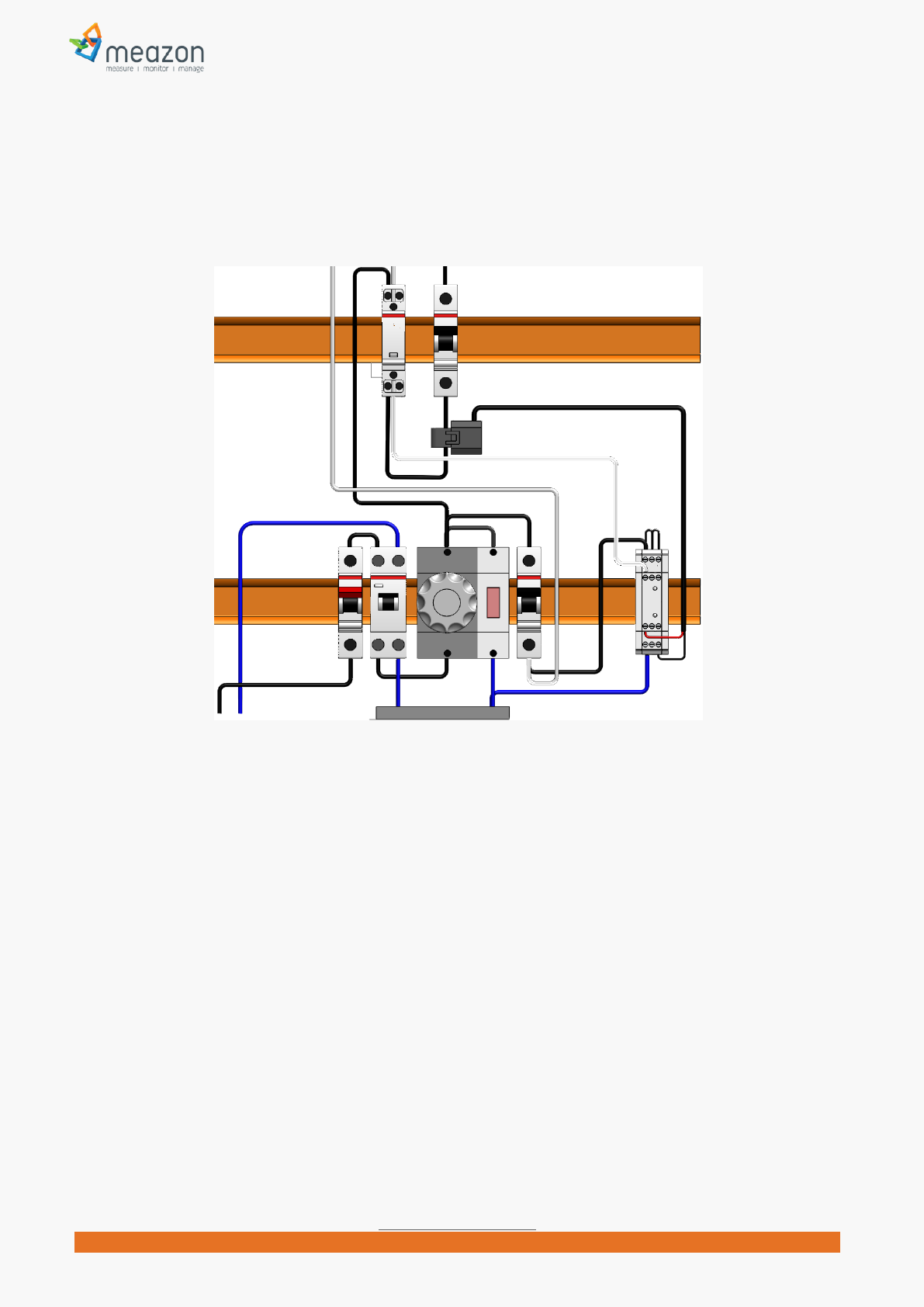
Upon completion of the electrical installation of DINRAIL, the electrical panel should appear as below:
Electrical Panel with DINRAIL 3-PHASE ADVANCED in a 3-Phase Panel
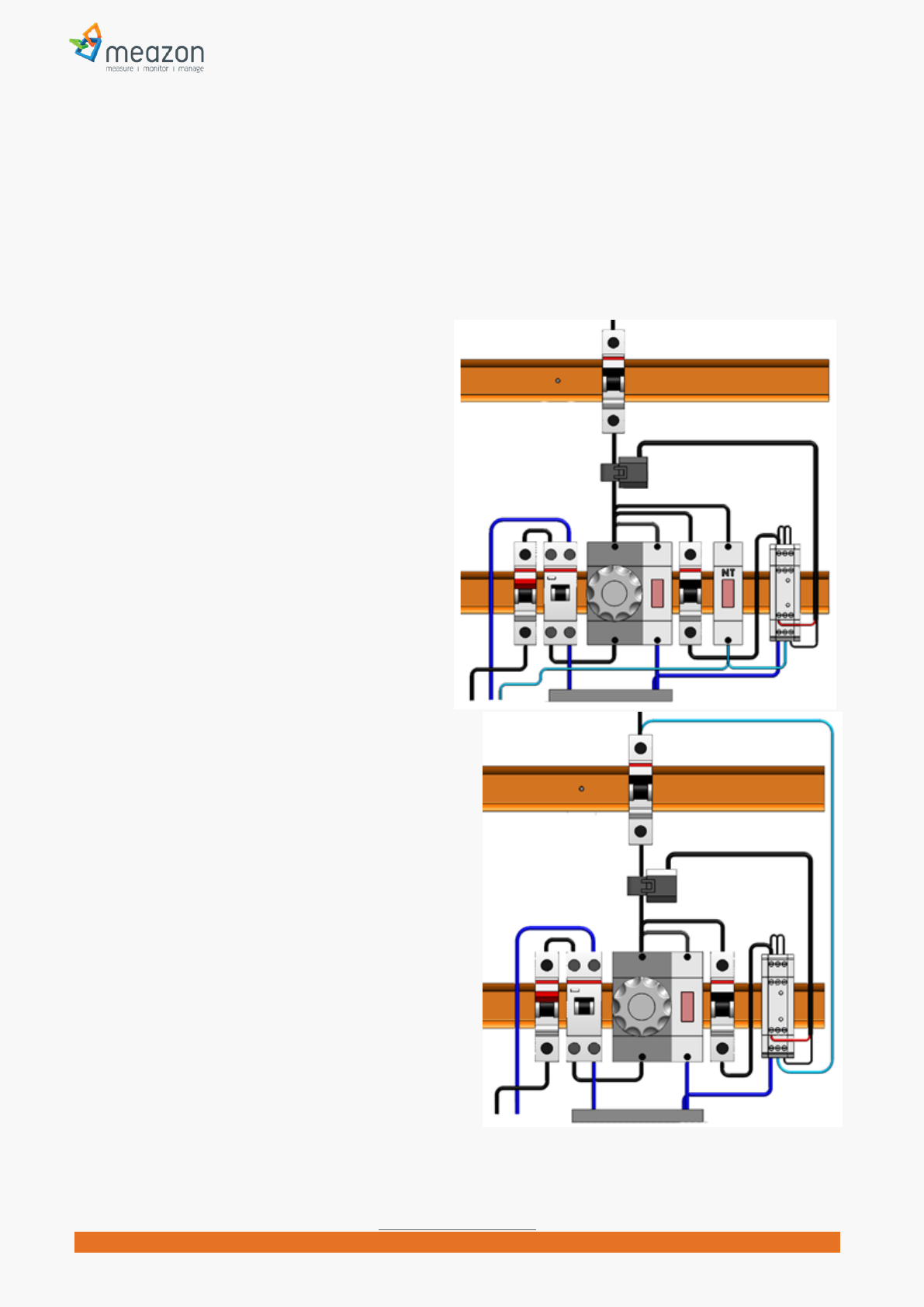
Installation in a single phase
Panel
WARNING! You can measure up to three (3) different loads.
To do this, follow the instructions of 3-phase installation
above. The only change in this procedure is that you have
to bridge terminals 1(L1) – 2(L2) - 3(L3).
Electrical Panel with DINRAIL 3-PHASE ADVANCED at
Single-Phase Panel
8
MEAZON ELECTRONIC SYSTEMS S.A.
N.E.O PATRON ATHINON 57, 26442, PATRA, Greece
Greeceinfo@meazon.com support@meazon.com +30 2610 430000
www.meazon.com
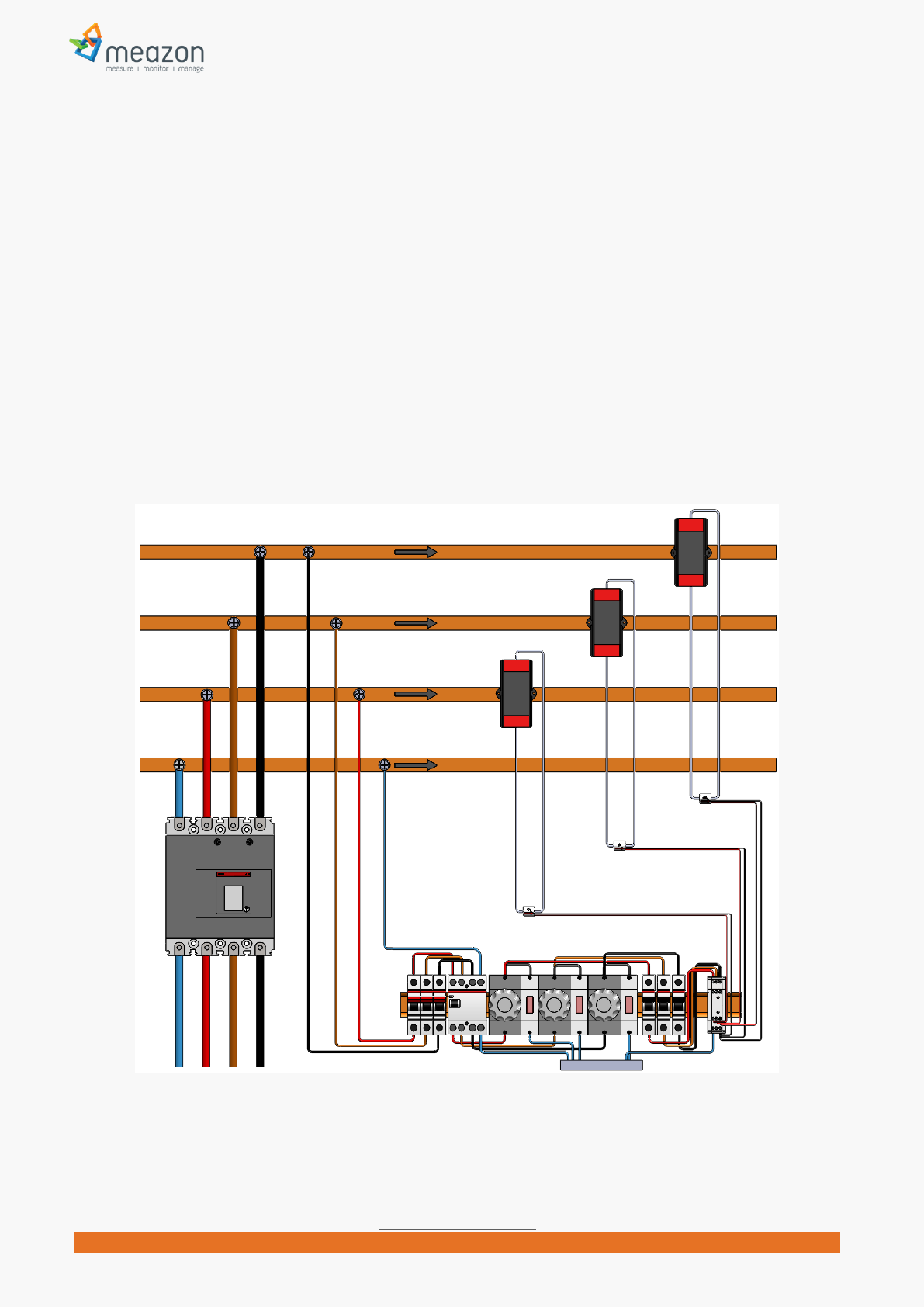
Installation for loads up to 2400A
WARNING! The following instructions relate only for DINRAIL version 5A. Using 5A version you can monitor
high current electrical loads up to 2400 Amperes (nominal load).
PRECONDITION! The electrical installation must include current transformers with secondary winding current
max output 5 Ampere.
Follow the instructions of 3-phase installation above.
Connect a wire to the -K- output of the secondary winding of phase L1 current transformer.
Pass the wire through the coil of our DINRAIL current transformer provided (the red wire of this CT
must be connected to contact 10 -CTR1- of the DINRAIL). The arrow illustrated on our CT must have
K-to-L direction.
Connect the remaining edge of wire to the -L- input of the secondary winding of phase L1 current
transformer.
Repeat the process for the other two current transformers.
Electrical Panel with DINRAIL 3-PHASE ADVANCED version 5A in a 3-Phase Panel
9
MEAZON ELECTRONIC SYSTEMS S.A.
N.E.O PATRON ATHINON 57, 26442, PATRA, Greece
Greeceinfo@meazon.com support@meazon.com +30 2610 430000
www.meazon.com
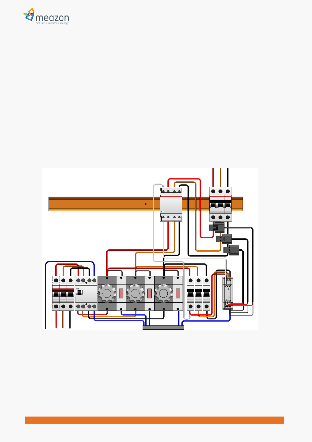
External Power Relay installation examples
WARNING! Use Power Relays with coil less than 50 VA.
3-phase Power Relay installation
Place Power Relay at the rail.
Disconnect the conductors from the loads to be controlled and connect them to the power input
connectors of the Power Relay.
Connect the power outputs of the Power Relay to the loads with the same order.
Connect a conductor from any phase to the Power Relays Coil input connector.
Connect a conductor from the Power Relays Coil output connector to the DINRAIL terminal 7 (RN).
Electrical Panel with DINRAIL 3-PHASE ADVANCED at a 3-Phase Panel and external 3-phase power relay
10
MEAZON ELECTRONIC SYSTEMS S.A.
N.E.O PATRON ATHINON 57, 26442, PATRA, Greece
Greeceinfo@meazon.com support@meazon.com +30 2610 430000
www.meazon.com
1-phase Power Relay installation
Electrical Panel with DINRAIL 3-PHASE ADVANCED at a single-Phase Panel and external single-phase power relay
11
MEAZON ELECTRONIC SYSTEMS S.A.
N.E.O PATRON ATHINON 57, 26442, PATRA, Greece
Greeceinfo@meazon.com support@meazon.com +30 2610 430000
www.meazon.com
Indication contact installation examples
Brief description
DinRail3-Phase Advanced connector 5 (NT) is a general purpose indication contact that can be used as a
useful information input to your system, under certain circumstances.
It operates under “Neutral detection” logic. The usage of this contact is shown on the following examples.
Night tariff indication example
Connect a conductor from the output of the
“night tariff” indication led to the DINRAILS
connector 5 (NT).
The picture in the right shows how to connect
“night tariff” indigation. DINRAIL would inform your
system for the status of “night tariff” change
(enabled or disabled) in your appliance.
Miniature circuit breaker (MCB) indication
example
WARNING! The following connection would have effect
only for loads that include Neutral connection. It would
not have any effect e.g. for 3-phase loads without
neutral.
WARNING! The following connection would have effect
only for operating loads. If a load has been stopped e.g.
by a switch, DINRAIL would not detect any change of
the MCB.
Connect a conductor from the output of the
MCB to the DINRAIL connector 5 (NT).
The picture in the right shows how to connect MCB
indigation. DINRAIL would inform your system for the
status of MCB change (enabled or disabled) in your
appliance.

12
MEAZON ELECTRONIC SYSTEMS S.A.
N.E.O PATRON ATHINON 57, 26442, PATRA, Greece
Greeceinfo@meazon.com support@meazon.com +30 2610 430000
www.meazon.com
About MEAZON
MEAZON acts as a catalyst to the energy efficiency market. We design and manufacture
revolutionary small size energy meters and integrate them with cloud technology. We build on open
standards and provide insights in energy consumption of commercial and residential buildings. This
way we drive significant energy efficiencies. For more information visit www.meazon.com.
Contact Information
N.E.O PATRON ATHINON 57, 26442, PATRA, Greece
Telephone: +30 2610 430000
24 Fokidos Str., 15126, Ampelokipoi, Athens, Greece
Telephone: +30 210 8020205
E-mail:info@meazon.com
Copyright © 2014, MEAZON S.A.
NOTE: This equipment has been tested and found to comply with the limits for a
Class B digital device, pursuant to part 15 of the FCC Rules. These limits are
designed to provide reasonable protection against harmful interference in a
residential installation. This equipment generates uses and can radiate radio
frequency energy and, if not installed and used in accordance with the instructions,
may cause harmful interference to radio communications. However, there is no
guarantee that interference will not occur in a particular installation. If this
equipment does cause harmful interference to radio or television reception, which
can be determined by turning the equipment off and on, the user is encouraged to
try to correct the interference by one or more of the following measures:
- Reorient or relocate the receiving antenna.
- Increase the separation between the equipment and receiver.
-Connect the equipment into an outlet on a circuit different from that to which the
receiver is connected.
-Consult the dealer or an experienced radio/TV technician for help
Changes or modifications not expressly approved by the party responsible for compliance
could void the user's authority to operate the equipment. This device complies with Part
15 of the FCC Rules. Operation is subject to the following two conditions:
(1) this device may not cause harmful interference, and
(2) this device must accept any interference received, including interference that may
cause undesired operation.