MEDIACOM RH-1112 WIRELESS MICROPHONE User Manual
MEDIACOM INTERNATIONAL (LLC) WIRELESS MICROPHONE Users Manual
MEDIACOM >
Users Manual

1
PROFESSIONAL
WIRELESS MICROPHONE
INSTRUCTION MANUAL
Thank you for buying our excellent wireless microphone series products
before you use our products please read this owner's manual,
So that you can enjoy it.
CONTENTS
l System composition ……………………….…. 2
l Main features ……………………….……….…. 2
l Introduction
n Operation of the microphone …. …………...3
n Operation of the receiver ……..................... 3
l Care of your unit ……….………………….….... 5
l Trouble shooting ………………..………….……5
l Specification ……...…………..……….…..……..6
2
SYSTEM COMPOSITION
1. One (1) Receiver
2. Two (2) Wireless Microphones
3. One (1) Audio Connecting Cable
4. Instruction manual
5. “AA” Batteries
MAIN FEATURES
1. VHF 210-270 MHz band to avert interfering frequency.
2. “Sing-Low” tension design. This ensures continuous uses even if battery power is low.
3. Multi-level High Frequency and Mid Frequency Narrow band filter to dispel any
possible interfering signals.
4. Using AL C design, don't worry the great volume so that distortion.
6. LED Battery Power Indicator on in the microphone.
7. Uses Quartz Crystal Oscillating circuits to ensure a steady frequency signal.
8. With noise-lowering technology
9. The Receiver uses Multi-level High Frequency to provide fast signal response
10. It has channel separate outpouring and mix outpouring and it can be connected with
the sound-adjusting stage and the karaoke enlarger.
11. Special Multiple Noise-Detector and Mute Control functions to avoid or minimize
signal interference.
12. With built-in signal range expander and re-echo reducer.
13. Excellent Chipset with high quality component to produce very good sound timbre
14. Ideal signal range of 30 meters, but can operate up to 180 meters in open area.
15. It is suitable for small and large stages ballrooms, auditorium, classrooms and
Families.

3
INTRODUCTION
1. OPERATION of the microphone
1) Screw open the battery box, then put in the “AA” batteries while ensuring the
polarities are correct.
2) Switch “ON” the microphone. If the LED does not flash once, or if LED is on
continuously, check the batteries. The supplied batteries may already be low on
power. Change the battery if needed.
3) Flick the switch to “STAND BY” (middle) mode when unit is not to be used
immediately. (Note: the power is still “ON” and the battery is still being used on a
slower pace.)
4) Remove the batteries from the microphone if it will not be used for long period of time.
This will prolong the power of the batteries. It will also avoid the microphone from
being ruined due to battery leaks.
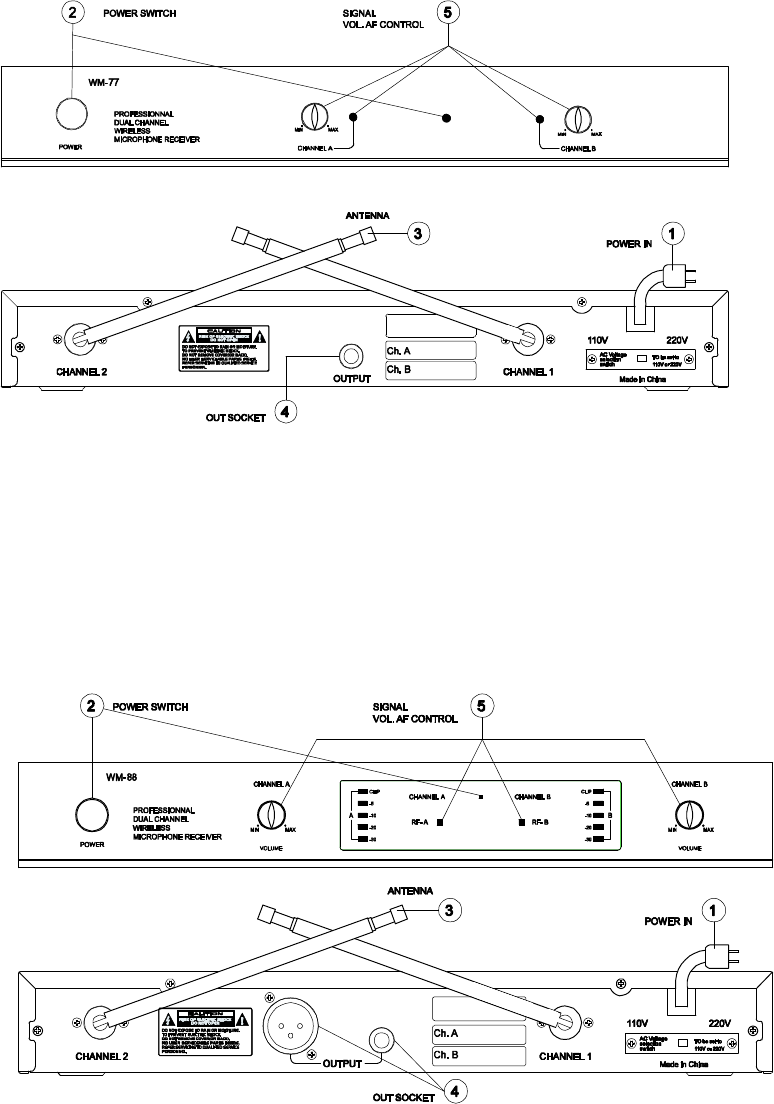
2. OPERATION OF THE RECEIVER
1) Before plugging the unit to a wall power socket, check the supplied power from the
source and ensure that the voltage is 100V ~240V/50-60Hz.
2) Push the power switch to “ON”. The LED will light up.
3) Pull out antennas A & B. They must be standing perpendicular to the machine.
4
4) Plug one end of the supplied Audio Connecting Cable into "OUTPUT" socket of the
Microphone Receiver. Connect the other end of the Audio Connecting Cable in the “MIC
IN 1 ” or MIC IN 2” sockets located in front of the to the DVD Player/Amplifier.
(note: Two (2) Microphone Receivers can be connected and used simultaneously using
the “MIC IN” sockets without causing signal lost or interference.)
5) When the Microphone Receiver is working, all the LED lights are lighted.
6) Adjust the Signal Strength of the Microphone Receiver by turning the knob clockwise
or counter-clockwise, depending on the size of the area and the distance of
Microphone to the Receiver.
7) LED shall move up or down to indicate the strength of the signal.
5
(note: The knob in front of the Microphone Receiver must not be used as volume control to
avoid signal feedback from the speakers. Use the knob in front of the DVD
Player/Amplifier to adjust the volume.)
CARE OF YOUR UNIT
1. Make sure the Receiver is placed and installed at least 1meter from the floor, and 1
meter from the wall. Antennas should be put out fully to ensure optimal signal
reception.
2. Avoid blocking the Microphone Receiver when used to prevent signal interruptions.
3. Do not throw, drop, shake, or toss Wireless Microphone. Sensitive circuits and parts
might be damaged.
4. Do not place the machine on direct sunlight, rain and moist areas. And put it in a
place as far as possible from the any magnetic field.
5. Do not open the Microphone Receiver to avoid being electrocuted. Allow only
authorized technician to service the unit
TROUBLE SHOOTING
1. The Receiver is On, but the LED Power Indicator is not lighted
Make sure if the power cable is well attached to the power source.
2. When you speak, the signal lighted but no sound output
Turn the switch to "STAND BY" Microphone (middle), (only for MODEL-88)
3. The Microphone and the Receiver is ON but no Sound is produced.
(a) Make sure the antennas are up. (b) Nothing is blocking the Reciever. (c) Make
sure Batteries are working. (d) Check the connection of the Audio Connecting Cables.
(e) Check the signal or volume knobs on the Receiver or on DVD Player/Amplifier. (f)
Tap lightly or speak on the Microphone to see if the LED signal indicator on the
Receiver is responding. The lights must move up or down.
4. Timbre Becomes Bad
(a) Check Battery Power of the Microphone. The LED on the Microphone must not
be always “ON”. Otherwise, need to change the battery. (b) Check the position of
the Signal Knob on the Microphone Receiver. (c) Do not use two Microphone
Receivers with the same frequencies at the same time.
Do not attempt to open and repair the Microphone and Receivers. Bring whole unit
to your nearest service center.

6
SPECIFICATION
General Specification
Audio Frequency Response: 40 ~ 18KHz
Dynamic Range: ≥80dB
T.H.D. at 1kHz:≤0.5%
Signal-to-Noise Ratio: ≥80dB
Operating Range:30M
Carrier Frequency Range: 210 ~ 216MHz
Audio Level Meter : 5 step LED
Carrier frequency Display :LED Indicator
Transmitter: Receiver:
Frequency Stability: ±0.005% Sensitivity(S/N=30dB): <2μV
RF Output Power: ≤30mW Image Rejection:>50dB
Spurious Rejection:>50dB De-Emphasis: 50μS
Modulation Mode: FM Audio Output Impedance: 600Ω±10%
Maximum Deviation Range: ±20KHz
Audio Output Level :0~0.5V
Microphone Mode: Dynamic Power Supply: AC100~240V 50/60Hz
Pre-Emphasis: 50μS Power Consumption:4.5W
Power Consumption: <35mA
NOTE: This equipment has been tested and found to comply with the limits
for a Class B digital device, pursuant to part 15 of the FCC Rules. These
limits are designed to provide reasonable protection against harmful
interference in a residential installation.
This equipment generates, uses and can radiate radio frequency energy and,
if not installed and used in accordance with the instructions, may cause
harmful interference to radio communications. However, there is no
guarantee that interference will not occur in a particular installation.
If this equipment does cause harmful interference to radio or television
reception, which can be determined by turning the equipment off and
on, the user is encouraged to try to correct the interference by one or
more of the following measures:
—Reorient or relocate the receiving antenna.
—Increase the separation between the equipment and receiver.
—Connect the equipment into an outlet on a circuit different from that
to which the receiver is connected.
—Consult the dealer or an experienced radio/TV technician for help.