MEIAN Technology FT-89R Wireless PIR detector User Manual FT 89R Wireless PIR detector
Shenzhen Meian Technology Co.,Ltd . Wireless PIR detector FT 89R Wireless PIR detector
Users Manual
External powered DC12V
Static current consumption: 18mA
Alarm current consumption: 30mA
When powered,the green LED light for 3
seconds and flicker 2 seconds and off
the red LED flicker about isseconds,after
3 minutes,the detector comes into work
states.
Alarm mode:Red LED light about 3S
Relay output:NC
Wireless transmitting distance:150m
Transmitting frequency:433MH
The max recharge caurrent: 120mA
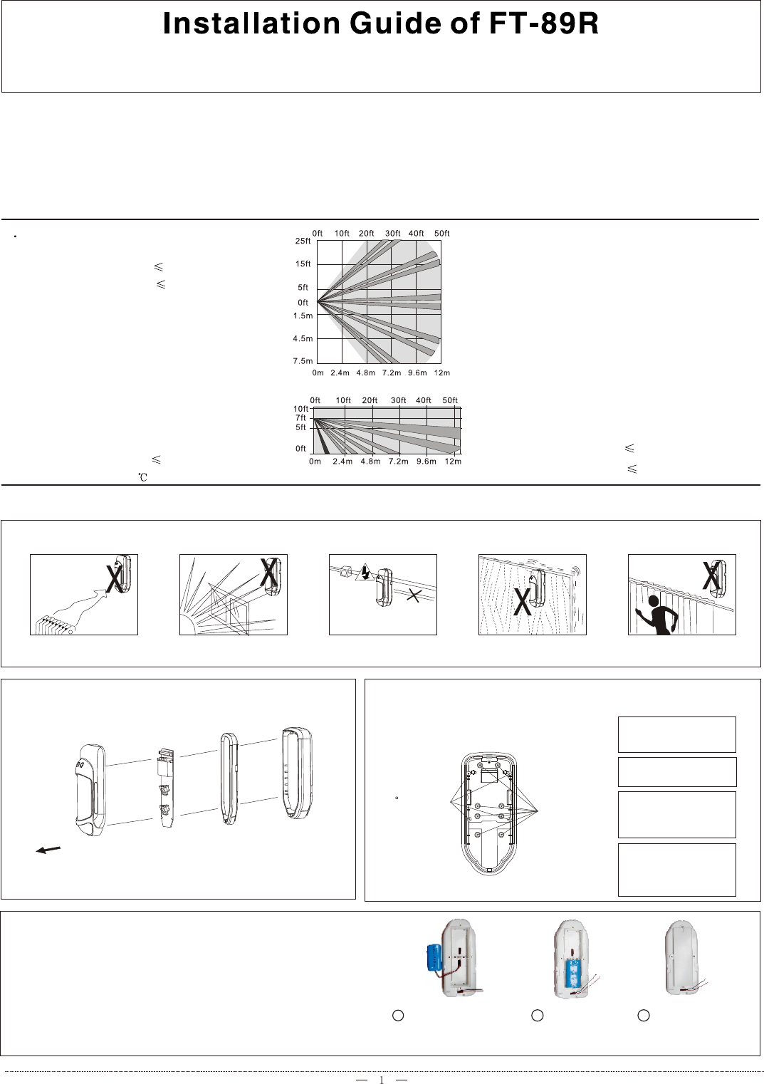
Detection range:12m(25 )
3.Installation
2 Specification
3.1 Guide
Do not face to cold or
heat source
Do not fact to sun light Keep away from high-
voltage wire
1.Introduction
Installation base
should be stable
Do not face to metal wall
FT-89R is the best indoor/outdoor motion detector with passive infrared and microwave.It's water proof and all weather resistant with two layer
stable housings.FT-89R combines a variety of detection techniques which enable it to work in the most difficult environment where needs high security
while maintaining immunity to false alarm.The infrared sensor adopts nice lens produce three-dimensinal thermal imaging of the protected area .
Combinging the four-element microwave scanning contributes to an amazing detection capacity.Using this technique allows high sensitivity but
lowest false alarm.FT-89R is equipped with unique protection mechanisms against any attempt to damage or to disable its operation.
3.2 Disassemble guide
2.Pull out the bottom of the cover
3.Remove the PCB
1.Loose screw
Internal battery-powered
Low battery ararm:2t will send Low battery
report when the detectoy low battery
and send battery resume report when the
battery resume
Relay outpnt:N/O(when external power
disconnect,the Rely output will convert
to N/O from N/C afert powered by battery
about 2 minutes,external power resume by
contrary.)
Static current consumption: 18mA
Alarm current consumption: 80uA
4.Remove the middle case
Enstarlation
Suggest installation height:2-3
meters from ground
45 corner
fixing Surface
fixing
A.Mark the drilling
points and make
holes.
B.Draw the cable
from back channel
C.Fix the base
cover on the wall
with two screws.
D.Put the PCB back on
the cover with clips and
fasten screws.
Suggest corner installation
3.3. Stand-by battery replacing and using
When battery is lower power, it will send related signal
to control panel,so user should replace battery with
same spec.(as right fig.)
On BUS working mode,if this model of detector more than
4pcs in the system,you need put battery inside to assure
the system will not overload.
123
Open battery box Install new
battery
Put on the cover
and fix with
svrews
Wireless PIR Detector
z
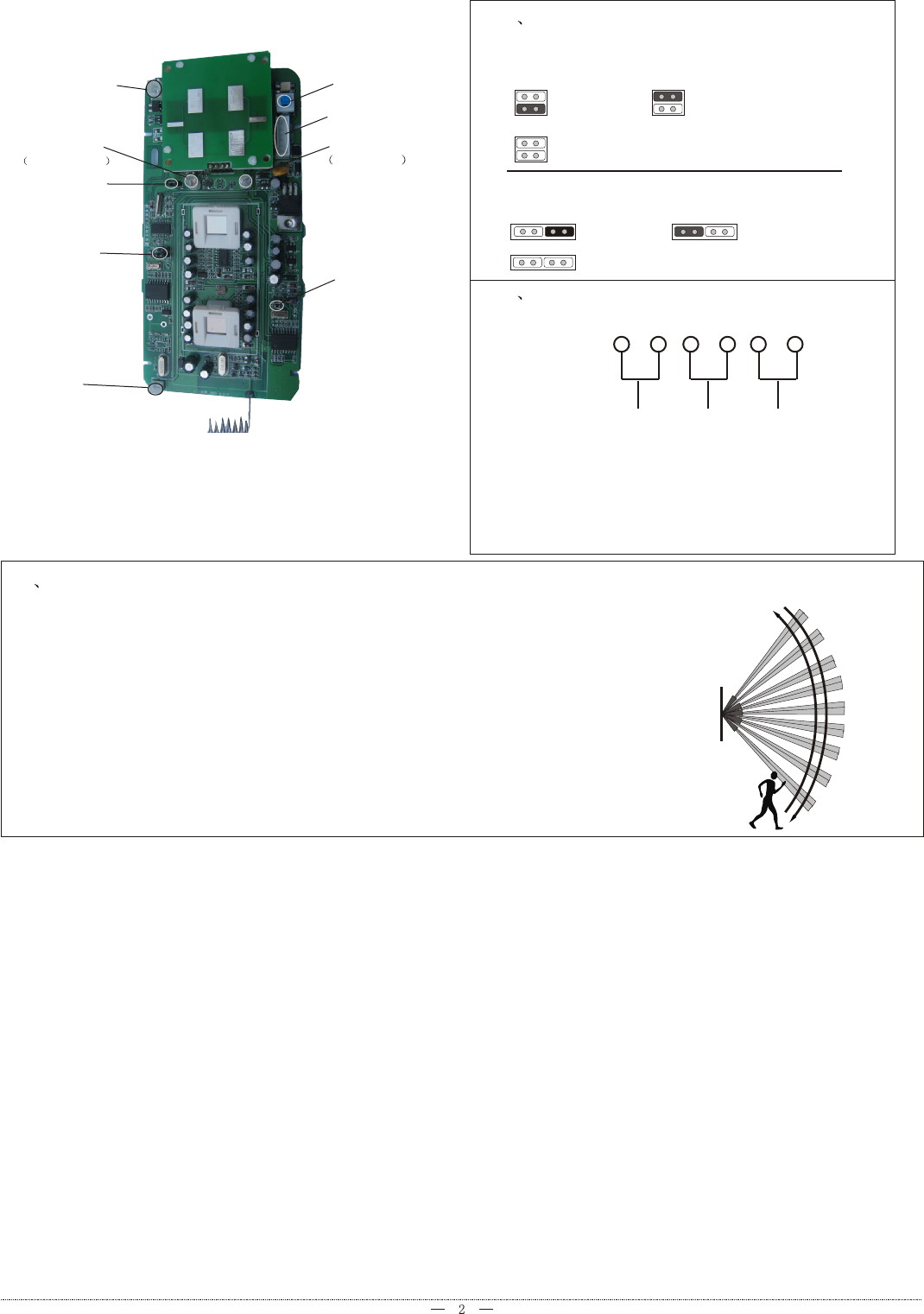
3.8 Perform motion test to the detect ion area: install th e cover and close thefasten part (refer to the
right diagram)
1. Start the test at least 2 minutes after power supply
2. Crossing to any direction of the detection area, your walking with 0.75m/s will cause the LED indicator
to light for 2-3 seconds (refer to the right diagram)
3 .Perform motion test from contrary directions in order to confirm the boundary of two sides. Make
confirmed that detection center pointing to the center of protected area.
4. Away from the detector 3 to 6 m, raise slowly your arm and reach into the detection zone, mark the lower
limit of PIR detection. Do the same step to confirm the upper limit.
5.the center of detection zone should not uphill incline. To obtain a good detection range , please adjust the
vertical detection range, en-sure the detector is in a correct position.
6. After MW sensitivity or detection angle are adjusted, walking test must be performed according to the
above steps.
3.4 Fanction explanation:
Solar board
connector
Green LED
Pretrigger LED
Anti-strong
light switch
Battery
connector
Trigger pluse
choose jumper
switch
Trigger pluse
choose jumper
switch 1
Tamper switch
Wiring terminal
Red LED
alarm LED
3.5 Function of jumper switch:
Trigger pluse count,choose jumper switch 1,
accroding to infrnred sensor 1
3.6 Wiring terminal
+-
AlarmTamp 12V
PowerAlarm
Tamper
Alarm:When the external power supply for 2-10 minutes,
Alarm ouput is N/C
Alarm:When the external power disconnect about 2-10
minutes,Alarm output convert to N/O on wireless mode
One Pluse Two Pluse
Three Pluse
Trigger pluse connt,choose jumper switch 2,
accroding to infrnred sensor 2
One Pluse Two Pluse
Three Pluse
3.7 Coding
Whenthe alarm panel enter coding mode,please press the
tamper switch of FT-89R for 3 seconds,immediately then
loose,when you can hear a hing sonnd from panel ,which
means coding successfally.
FCC WARNING
Changes or modifications not expressly approved by the party responsible for compliance could void the user's authority to operate
the equipment.
This equipment has been tested and found to comply with the limits for a Class B digital device, pursuant to Part 15 of the FCC
Rules. These limits are designed to provide reasonable protection against harmful interference in a residential installation. This
equipment generates uses and can radiate radio frequency energy and, if not installed and used in accordance with the instructions,
may cause harmful interference to radio communications. However, there is no guarantee that interference will not occur in a
particular installation. If this equipment does cause harmful interference to radio or television reception, which can be determined
by turning the equipment off and on, the user is encouraged to try to correct the interference by one or more of the following
measures:
-- Reorient or relocate the receiving antenna.
-- Increase the separation between the equipment and receiver.
-- Connect the equipment into an outlet on a circuit different from that to which the receiver is connected.
-- Consult the dealer or an experienced radio/TV technician for help.