MEIAN Technology MC-335R Wireless PIR Detector User Manual MC 335R Wireless PIR Detector
Shenzhen Meian Technology Co.,Ltd . Wireless PIR Detector MC 335R Wireless PIR Detector
Users Manual
拨码开关功能说明
拨码开关
Current consumption:
Static≤30μA,Alarm≤20mA(433MHz)
4.2 pet-immunity guidebook
The installation height of
2.2m to 2,4m is available
pet-immunity height
2.2-2.4m2.2-2.4m
≤15Kg
the pet is smaller than 15kgthe top of the detecting
area is the non-pet-immunity
area
NO
OK
2.2--2.4m
2.2-2.4m
≤20Kg
15。
the pet is smaller
than 20kg
prevent direct the
places where the pets can
clamb up
X
P/N 20110301-2
MC-335R Wireless PIR Detector
4.3 Introduce DIP function:
MC-355R can choose 3 kinds of pulse as follows:
1-pulse: Alarm 1-pulse.
2-pulse: Alarm 2-pulse。
3-pulse: Alarm 3-pulse(Factory default)。
Higher pulse counting and lower catch performance and can avoid false alarm
1 2
Modes
1-pulse
2-pulse
3-pulse
ON
ON
OF F
OFF
OFF OF F
6. Customer service
Our products are very reliable,but for some special reasons, the working performance will be limited in certain range.
We here list some cases as follows:
①. The voltage of control panel is not stable;
②. Low-voltage of the detector.
For any help please contact with our company and your could visit our website for more information.
Warning: We are not responsible for the problem caused by improper operation by users!
① Set as Test Mode to precess walk-test,pulse count set as 1,2 or3。
④ Make sure the detection centre at the proper place. Should properly adjust the detection
area if you can not get an ideal detection area.
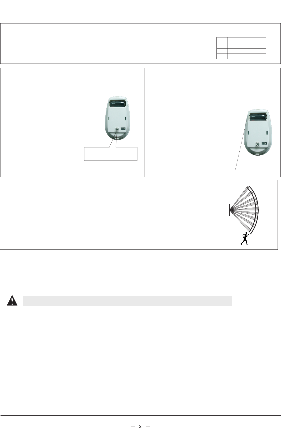
② Walk across the far edge of coverage area at the speed of 1 step/second(about0.75m/s)
The LED will flash for seconds then alarm(as shown in the right figure)
5. Walk test in coverage area:
⑤ After adjust the detection angle , should redo the walk test as above.
⑥ Please change TEST mode to NORMAL mode after the Walk-test .
③ Do walk-test in opposite direction to confirm the boundary of both sides, Make sure the
detection centre pointing to the centre of protected area.
MC-355R can set three modes as follows:
Test Mode:Emitting alarm signa nce detector is triggered. No time-lag between two emissions.
Power-saver mode:Send detection signal of detector and battery status
Coding Mode:Press tamper switch for more than 3 seconds and send an identification code to receiver.
Dip switch 3 and 4 set modes
Modes
ON OFF Test
OFF ON Power-saver
OFF OFF Coding
34
Press the tamper switch
for study the ID code
Insert one new battery
4.4. Coding method between detector and
control panel:
① Coding set:
Install the battery LED flashes,when
the detector gets stable after seconds,
press tamper switch for more than 3
seconds and detector will send a wireless
signal. If the control panel receives the
signal and give the response sound then
code successfully. Please refer to control
panel manual for details.
② If short-circuit pin “A” with a jumper
then the tamper alarm function invalid.
4.5. Detection distance adjustment and
battery changes
① Shorten detection distance by pushing down the PCB
and vice versa User can adjust it to meet different need. As
shown on the right picture, the
detection distance is the farthest.
②When the signal between detector
and control panel becomes weak.
That means a low battery condition.
Users should change new battery
with same type. Pull out the base
cover and change battery.Please pay
attention to the positive and negative.
P/N 20110301-2
FCC WARNING
Changes or modifications not expressly approved by the party responsible for compliance could void the user's authority to operate
the equipment.
This equipment has been tested and found to comply with the limits for a Class B digital device, pursuant to Part 15 of the FCC
Rules. These limits are designed to provide reasonable protection against harmful interference in a residential installation. This
equipment generates uses and can radiate radio frequency energy and, if not installed and used in accordance with the instructions,
may cause harmful interference to radio communications. However, there is no guarantee that interference will not occur in a
particular installation. If this equipment does cause harmful interference to radio or television reception, which can be determined
by turning the equipment off and on, the user is encouraged to try to correct the interference by one or more of the following
measures:
-- Reorient or relocate the receiving antenna.
-- Increase the separation between the equipment and receiver.
-- Connect the equipment into an outlet on a circuit different from that to which the receiver is connected.
-- Consult the dealer or an experienced radio/TV technician for help
This device complies with part 15 of the FCC Rules. Operation is subject to the following two conditions: (1) This device may not cause harmful
interference, and (2) this device must accept any interference received, including interference that may cause undesired operation.
nce detector is trigg ered
l o
o