MEILOON CTRL24GAWRX Wireless Speaker Amplifier User Manual Layout 1
Meiloon Industrial Co., Ltd. Wireless Speaker Amplifier Layout 1
MEILOON >
Users Manual

CONTROL 2.4G
ON AIR™
OWNER’S GUIDE
®
THANK YOU FOR CHOOSING JBL
2
For more than 60 years, JBL has been involved in every aspect of music and
film recording and reproduction, from live performances
tothe recordings you play in your home, car or office.
We’re confident that the JBL system you have chosen will provide every note
of enjoyment that you expected – and that when you think about purchasing
additional audio equipment for your home, car or office, you will once again
choose JBL.
Please take a moment to register your product on our Web site at
www.jbl.com. It enables us to keep you posted on our latest advance-ments,
and helps us to better understand our customers and build products that meet
their needs and expectations.
The JBL OnAir™ Control 2.4G is an advanced wireless loudspeaker system
that allows you to enjoy your favorite music in remote locations around your
home or add surround speakers to your home theater system without running
wires to the back of the room. To ensure trouble-free performance, please
carefully read these instructions completely before connecting or using the
system.
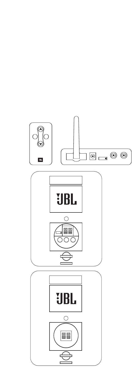
Control 2.4G
RIGHT CHANNEL SPEAKER
TO LEFT SPEAKER
+–
Control 2.4G
ID
CODE
1234
DC 20V SUB OUT LINE IN
LEFT CHANNEL SPEAKER
TO RIGHT SPEAKER
+–
Control 2.4G
RIGHT CHANNEL SPEAKER
TO LEFT SPEAKER
+–
INPUT
MUTE
VOL
INPUT
RL
ID
CODE
1234
UNPACKING THE SYSTEM
Carefully unpack the system. If you suspect damage from transit, report it
immediately to your dealer and/or delivery service. Keep the shipping carton
and packing materials for future use. Open the package and verify the follow-
ing contents:
Included
1 x Transmitter Module
1xUniversal Power Supply for Transmitter
1x120V 2-prong AC power cord for Transmitter Power Supply
1x230V 2-prong AC power cord for Transmitter Power Supply
1xWallmount bracket for Transmitter with 2 x Pan head M3x4 machine
screws for attaching wallmount bracket to transmitter
4xsmall round self-adhesive feet – to be attached on Transmitter left
side panel if Transmitter to be used vertically
1 x Active Speaker/Receiver (Left channel speaker)
1xUniversal Power Supply for Active Speaker/Receiver
1x120V 3-prong AC power cord for Active Speaker/Receiver Power
Supply
1x230V 3-prong AC power cord for Active Speaker/Receiver Power
Supply
2xWallmount rotatable brackets for active speaker (Includes bar
wrench and back-up cords)
1xWallmount holder for Active Speaker/Receiver Universal Power
Supply
1 x Passive Speaker (Right channel speaker)
2xWallmount rotatable brackets for active speaker (Includes bar
wrench and back-up cords)
1xRemote Control
1xInterconnect cable (1m/3.3ft RCA – RCA)
1xInterconnect cable (1m/3.3ft RCA – 1/8” mini plug)
10m/33ft. x Speaker Wire
1 x Owner’s Manual (Multilanguage)
1xUSA Warranty Sheet
3
CONNECTIONS
+–
9
RIGHT CHANNEL SPEAKER
TO LEFT SPEAKER
ID
CODE
1234
DC 20V SUB OUT LINE IN
TO RIGHT SPEAKER
+–
+–
45
68 9
7
LEFT CHANNEL SPEAKER RIGHT CHANNEL SPEAKER
TO LEFT SPEAKER
RL
ID
CODE
1234
ABCD
INPUT
INPUTMUTE
VOL
1
2
03
NOTES:
For the sake of simplicity, we have used the terms “receiver” and “A/V receiv-
er” when describing the connections and operation, throughout the manual.
We feel that the majority of customers purchasing this system will connect it
to a receiver of some type. In the event that you are using an integrated ampli-
fier, separate surround processor or computer sound card, the instructions
would be applicable to your unit.
The JBL OnAir Control 2.4G is designed for use worldwide and includes univer-
sal power supplies for the Transmitter Module and Active Speaker. Please be
sure to select and use the correct AC power cords (included) for your location.
The JBL OnAir may be connected to your existing audio system in several
ways. First, determine how you would like to use the JBL OnAir Control 2.4G,
then follow the set-up instructions for that application.
Application 1
Adding Surround Speakers to a home theater system.
Continue reading the instructions for Application 1 below.
Application 2
Adding speakers to remote locations around your home.
Go directly to page xx.
Application 1
Adding Surround Speakers to a home theater system.
Determine if your receiver contains pre-amp outputs for rear-/surround-chan-
nels, usually indicated by RCA type jacks on the back of the receiver labeLED
as surround pre-out. (Please refer to your AV receiver’s owner’s manual to
confirm whether it includes the pre-amp outputs.) If your receiver includes
these outputs, follow the steps below.If not, connection is not recommended.
NOTE: Make sure power is turned off on all components.
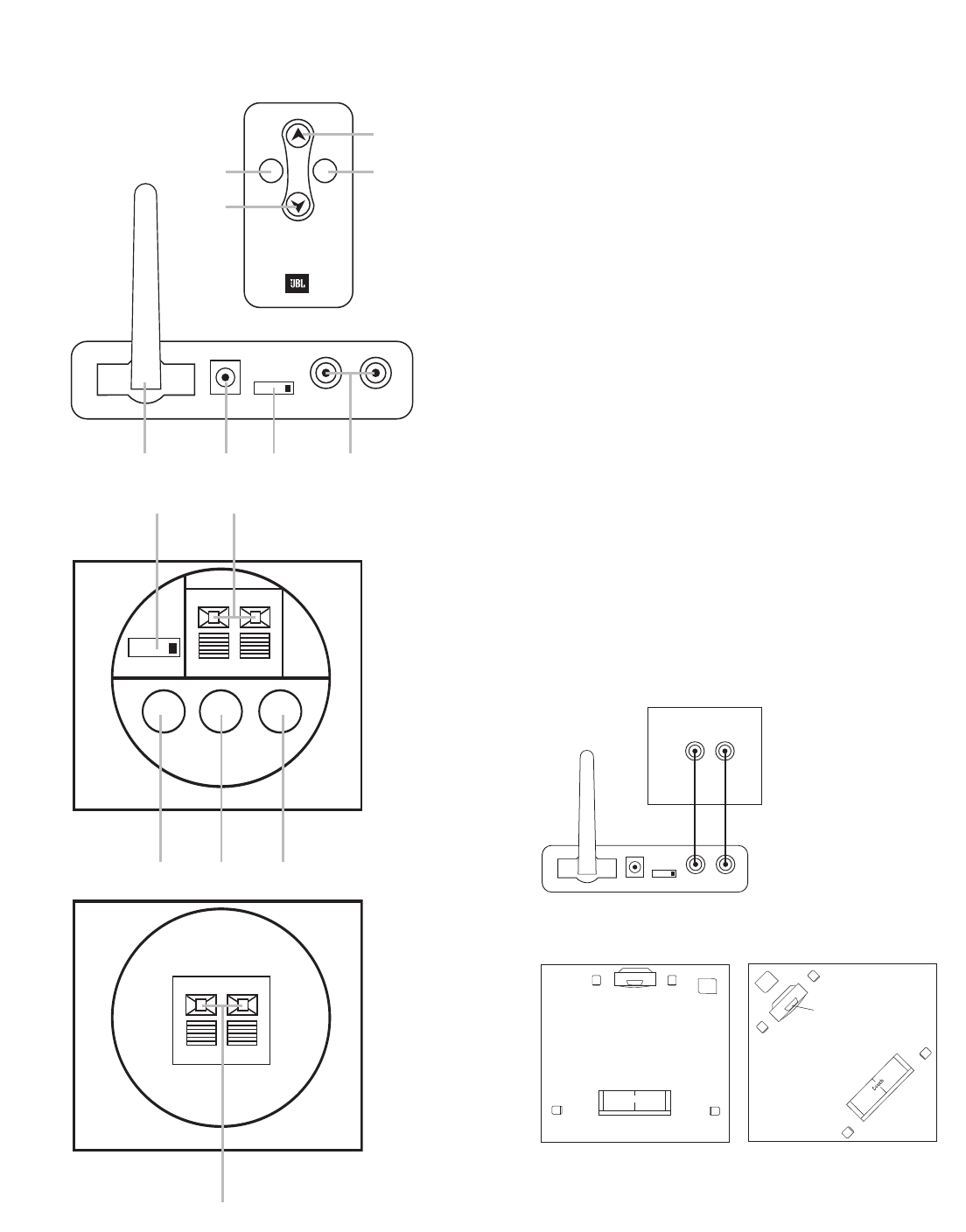
Step 1
Connect the interconnect cable (included) to the left and right surround/rear
pre-amp outputs on the back of your receiver and the input on the Transmitter
Module Das shown in Figure 1.
Step 2
Determine location of surround speakers.
(
Place the active (left) speaker in the recommended location for the left sur-
round speaker.
Left
Surround
Channel
Right
Surround
Channel
Left Front
Channel
Subwoofer Right Front
Channel
Center
Channel
Couch
L
Left Rear
Channel
Left
Surround
Channel
Right
Surround
Channel
Right Rear
Channel
Center Rear
Channel
Left Front
Channel
Subwoofer
Right Front
Channel
Center
Channel
INPUT
RL
RL
ID
CODE
1234
RECEIVER/PROCESSOR
Surround Channel
Pre-Amp Outputs
4
CONNECTIONS
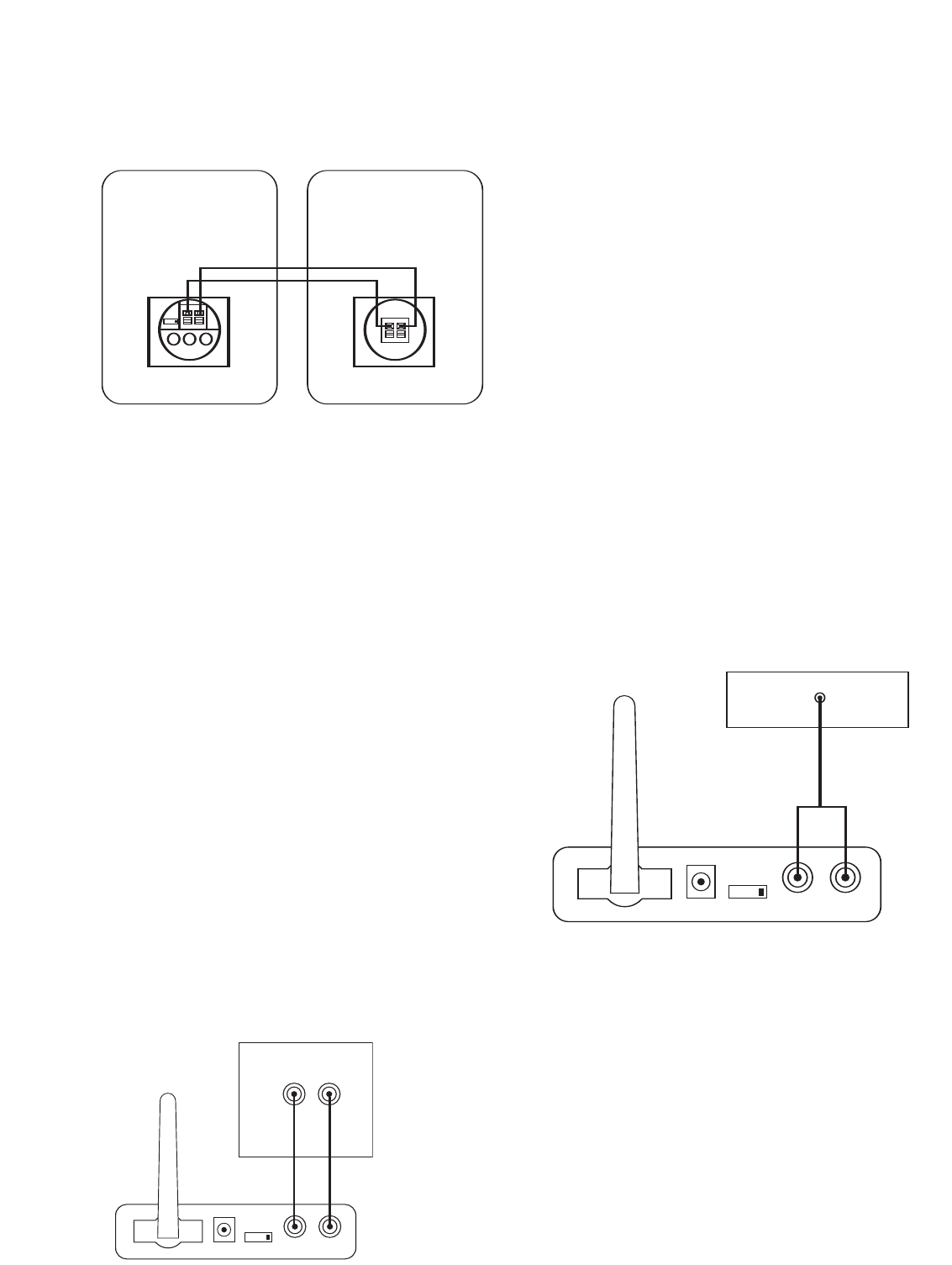
Step 3
Connect the speaker wire (included) to the push terminals on the Active
Speaker 5and the push terminals on the rear of the Passive Speaker. See
figure 4 .
Step 4
Plug the Transmitter Module and Active Speaker into the wall outlet. Make
sure the transmitter’s antenna Ais extended upwards.
Step 5
If necessary, configure your A/V receiver to activate the pre-amp level outputs
for the surround/rear channels. (Consult your receiver’sowner’smanual for
specific instructions.)
When connected properly, the top LED on the front of the Active Speaker
should be green. The bottom LED should flash green until the Transmitter and
Active Speaker “lock in”. It will then illuminate solid green also.
Application 2
Adding speakers to remote locations around your home
Determine if your receiver contains pre-amp outputs for front/main channels,
usually indicated by RCA type jacks on the back of the receiver labeLED as
pre-out. (Please refer to your receiver’s owner’s manual to confirm whether it
includes pre-amp outputs.) If your receiver includes these outputs, follow the
steps in CONNECTION OPTION A. If not, then you may hook the JBL OnAir
Control 2.4G to your portable audio player or computer through their head-
phone jacks as described in CONNECTION OPTION B.
NOTES:
Make sure power is turned off on all components.
Some computer sound cards also contain pre-amp outputs, if you would like to
connect the computer to the JBL OnAir Control 2.4G using pre-amp outputs on
you computer, follow the steps in CONNECTION A.
CONNECTION OPTION A
Connecting using the pre-amp outputs on your receiver
Step 1
Connect the interconnect cable (included) to the left and right front/main pre-
amp outputs or zone 2 outputs or REC Outputs and the inputs on the
Transmitter Module Das shown in figure 5.
INPUT
RL
RL
ID
CODE
1234
RECEIVER
Front/Main/Second Room
Pre-Amp Outputs
ID
CODE
1234
DC 20V SUB OUT LINE IN
LEFT CHANNEL SPEAKER
TO RIGHT SPEAKER
+
–
RIGHTCHANNEL SPEAKER
TO LEFT SPEAKER
+–
Step 2
Place the Active Speaker in the desired location in your home near an AC out-
let, as it needs to plug in to the wall.
Step 3
Connect the speaker wire (included) to the push terminals on the Active
Speaker 5and the push terminals on the rear of the Passive Speaker 9as
shown in figure 4 .
Step 4
Plug the Transmitter Module and Active Speaker into the wall outlet. Make
sure the transmitter’s antenna Ais extended upwards.
Step 5
If necessary, configure your receiver to activate the pre-amp level outputs for
the main/front channels. (Consult your receiver’s owner’s manual for specific
instructions.)
When connected properly, the top LED on the front of the Active Speaker
should be green. The bottom LED should flash green until the Transmitter and
Active Speaker “lock in”. It will then illuminate solid green also.
CONNECTION OPTION B
Connecting using the headphone jack on your portable audio player or
computer
NOTES:
Make sure power is turned off on all components.
Some computer sound cards also have external speaker outputs, this connec-
tion may be used instead of the headphone jack if desired.
Step 1
Connect the RCA – 1/8” mini jack cable (included) to the headphone output of
your portable audio player and the inputs on the Transmitter Module Das
shown in figure 6.
Step 2
Place the Active Speaker in the desired location in your home near an AC out-
let, as it needs to plug in to the wall.
Step 3
Connect the speaker wire (included) to the push terminals on the Active
Speaker 5and the push terminals on the rear of the Passive Speaker as
shown in figure 4.
Step 4
Plug the Transmitter Module and Active Speaker into the wall outlet. Make
sure the transmitter’s antenna Ais extended upwards.
When connected properly,the top LED on the front of the Active Speaker
should be green. The bottom LED should flash green until the Transmitter and
Active Speaker “lock in”. It will then illuminate solid green also.
INPUT
RL
ID
CODE
1234
Portable Audio Device or
Computer Headphone Jack (1/8") mini

Subwoofer Output
The JBL OnAir Control 2.4G wireless speaker system includes a subwoofer
output 7on the rear of the Active Speaker. This output allows you to feed the
low-frequency sounds to a separate powered subwoofer. A powered
ubwoofer will deliver deeper bass response than is possible with the speakers
alone.
To connect powered subwoofer to the Active Speaker, simply connect the SUB
OUT 7on the Active Speaker to the Line-In on the rear of the powered sub-
woofer using a 1/8” stereo mini-jack – dual-RCA cable* (Not included).
*One mini-jack – dual RCA cable is included with the system. If you are fol-
lowing application or connection option B above, you will need to purchase
this cable.
5
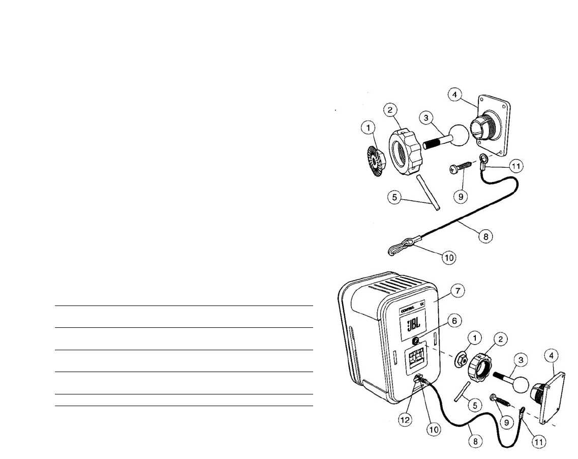
Wall Mounting the Speakers
Important safety note: Proper selection of mounting hardware not included
herein and proper assembly and installation of brackets, including but not
limited to selection of appropriate weight bearing support and bracket use with
the specified speaker only is the exclusive responsibility of the customer.
Manufacturer disclaims any liability for the selection of mounting hardware and
or bracket installation.
a. Loosen and remove the molded nut
™
by turning it counter clockwise. Use
the supplied metal bar
∞
if necessary by inserting it in one of the holes on
the molded nut
™
.
b. Pull the ball/shaft
£
out of the wall bracket
¢
.
c. Slide on the molded nut
™
onto the ball/shaft
£
with threaded opening facing
the ball, and thread on the metal nut
¡
all the way onto the ball/shaft
£
,with
the nut
¡
’s ”knurled” surface facing away from the ball.
d. Screw on the ball/shaft
£
into the threaded insert on the back of the speaker
cabinet
§
until it is fully seated against the bottom of the insert.
e. Tighten the ”knurled” nut
¡
using a crescent wrench until it is firmly seated
against the back of the speaker and has fully locked the ball/shaft
£
and the
speaker cabinet together.Pleace note that once this nut is tightened, it may
embed some marks on the back of the speaker where the attachment is
made. However, these marks will be covered by the nut
¡
.
f. The back-up cord
•
provided as an additional measure to prevent the fall of
the speaker in case the speaker becomes detached from the wall bracket.
One of the two lower screws
ª
that attach the wall bracket
¢
to the wall, will
need to go through the eyelet
⁄
at the end of the cord before going through
the wall bracket hole. Mount the wall bracket
¢
onto a wood stud on the wall,
using #10, minimum 1 inch long, pan head wood screws. Make sure that all 4
screws are driven into the stud and not in drywall. If the bracket needs to be
Adjusting the Volume
When using the JBL OnAir Control 2.4G wireless speaker system, turn the vol-
ume level on your receiver to approximately half-way. If using with a portable
audio device, turn its volume control to the maximum output. From this point
on, you will use the remote control included with the JBL OnAir Control 2.4G
wireless speaker system to adjust the volume.
To raise the volume, simply push up 1on the remote control
To lower the volume, simply push down 2on the remote control
Local Input
The JBL OnAir Control 2.4G wireless speaker system also includes a local
input 8on the rear of the Active Speaker. This input allows you to hook up a
portable audio player directly to the speaker wherever you may happen to be.
For example, you could have the system connected to your receiver as
described in Application 2, listening to a local FM station and then hook up
your portable music player to the local input and switch between the two dif-
ferent sources.
To connect portable audio player to the Active Speaker, simply connect the
headphone jack to the Line-In 8on the rear of the Active Speaker using a
1/8” mini-jack – 1/8” mini-jack cable (Not included).
To switch between the two sources, push the Input button (show button or #)
on the remote control.
Indicator Light Information
PPoowweerr IInnddiiccaattoorr LLEEDDIInnppuutt LLEEDD
((TToopp))((BBoottttoomm))
GGrreeeennSystem is on Transmitter and speaker are
communicating (RF lock)
BBlliinnkkiinngg GGrreeeennReceiving IR command Transmitter and speaker are not
from remote control communicating (No RF lock)
RReeddStandby
(no signal being received)
OOrraannggeeLocal input is selected
A Word About Wireless Products
The JBL OnAir Control 2.4G wireless speaker system utilizes and advanced
wireless transceiver operating in the 2.4GHz frequency band. This is the same
frequency band that is used for wireless home networks and high-quality
cordless phones. It also allows for the transmission of high-performance, full-
spectum sound to remote locations, wirelessly.
Interference
In the unlikely event that you experience interference when operating the sys-
tem you may change the channel in which the system operates. On the
Transmitter Module and the Active Speaker, there is a four-position “ID Code”
selector. Simply set the selectors to one of the other positions. The Transmitter
and Active Speaker must be set to the same position in order for the system to
function correctly.
Range
Like all wireless devices, the JBL OnAir Control 2.4G wireless speaker’s oper-
ating range may vary depending upon variables such as building construction
methods and materials, atmospheric conditions and other sources of interfer-
ence. Please consult your JBL dealer or distributor or visit us at www.jbl.com
for further information or assistance.
Wall and Stand Placement
Adjustable wall brackets are included for the two speakers and transmitter
module. The included bracket is for wall mounting only. It is not to be used for
ceiling mount.
OPERATION

mounted on drywall, the use of properly selected and installed wall-anchors
and screws is essential. Make sure that the screw head is at least 0.36 inches
(approximately 3/8 inches) or larger in diameter so that it can properly hold the
backup cord eyelet
⁄
.
g. Holding the speaker cabinet
¶
with both hands, reinsert the ball portion of the
ball/shaft
£
into the wall bracket
¢
.
h. Hand tighten the molded nut
™
while positioning the speaker for the intended
orientation.
i. Once the orientation of the speaker is finalized, use the metal bar
∞
in one of
the holes on the molded nut
™
and tighten securely.
j. Securely attach the other end
‚
of the backup cord
•
to the Control ONE, by
engaging it through the bar
¤
on the back speaker.
Also included with the system is a wall-mount holder for the Active Speaker’s
power supply. If desired, you may attach this holder to the wall and insert the
speaker’s power supply.
Wall Mounting the Transmitter Module
Step 1
Insert the two M3x6 machine screws through the wall bracket and into the
rear of the Transmitter module as shown in figure xx.
Step 2
Attach Transmitter module with wall bracket to the wall using suitable hard-
ware and wall anchors if necessary.
The JBL OnAir Control 2.4G wireless speakers each contain a ?”-20 threaded
insert on the bottom (to facilitate the use of third-party floor stands) and rear
(to facilitate the use of third-party wall brackets). Please consult your JBL
dealers for recommendations.
NOTE: Customer is responsible for proper selection and installation of appro-
priate 3rd-party wall brackets and/or floor stands.
Maintenance and Service
The satellite and subwoofer enclosures may be cleaned using a soft cloth
to remove fingerprints or to wipe off dust.
All wiring connections should be inspected and cleaned or remade peri-
odically. The frequency of maintenance depends on the metals involved in
the connections, atmospheric conditions and other factors, but once per
year is the minimum.
In the event that your system ever needs service, contact your
local JBL
dealer or distributor, or visit www.jbl.com
for a service center near you.
Specifications
Insert Specs (Mike)

JBL is a trademark of Harman International Industries, Incorporated, registered in the United States
and/or other countries. Pro Sound Comes Home and Studio Series are trademarks of Harman
International Industries, Incorporated.
Dolby and Pro Logic are registered trademarks of Dolby Laboratories.
DTS is a registered trademark of DTS, Inc.
®
PRO SOUND COMES HOME
™
Harman Consumer Group, Inc., 250 Crossways Park Drive, Woodbury, NY 11797 USA
8500 Balboa Boulevard, Northridge, CA 91329 USA
516.255.4JBL (4525) (USA only) www.jbl.com
© 2006 Harman International Industries, Incorporated. All rights reserved.
Part No.
406-000-05529-E
Declaration of Conformity
We, Harman Consumer Group International
2, route de Tours
72500 Château du Loir
France
declare in own responsibility that the products described in this
owner’s manual are in compliance with technical standards:
EN 61000-6-3:2001
EN 61000-6-1:2001 Laurent Rault
Harman Consumer Group International
Château du Loir, France 9/06
Federal Communication Commission Interference Statement
This equipment has been tested and found to comply with the limits for a Class B digital device, pursuant to Part
15 of the FCC Rules. These limits are designed to provide reasonable protection against harmful interference in
a residential installation.
This equipment generates, uses and can radiate radio frequency energy and, if not installed and used in
accordance with the instructions, may cause harmful interference to radio communications. However, there is no
guarantee that interference will not occur in a particular installation. If this equipment does cause harmful
interference to radio or television reception, which can be determined by turning the equipment off and on, the
user is encouraged to try to correct the interference by one of the following measures:
. Reorient or relocate the receiving antenna.
. Increase the separation between the equipment and receiver.
. Connect the equipment into an outlet on a circuit different from that to which the receiver is connected.
. Consult the dealer or an experienced radio/TV technician for help.
FCC Caution :To assure continued compliance, any changes or modifications not expressly approved by the
party responsible for compliance could void the user's authority to operate this equipment. (Example - use only
shielded interface cables when connecting to computer or peripheral devices).
FCC Radiation Exposure Statement
This equipment complies with FCC RF radiation exposure limits set forth for an uncontrolled environment. This
equipment should be installed and operated with a minimum distance of 20 centimeters between the radiator and
your body.
This device complies with Part 15 of the FCC Rules. Operation is subject to the following two conditions:
(1) This device may not cause harmful interference, and (2) This device must accept any interference received,
including interference that may cause undesired operation.