MERIT TECHNOLOGY MT-403 4 CH 2.4 GHz FHSS RADIO CONTROL SYSTEM User Manual PLANET 2 2 QSG
SHANGHAI MERIT TECHNOLOGY CORP. 4 CH 2.4 GHz FHSS RADIO CONTROL SYSTEM PLANET 2 2 QSG
User Manual
Product specifications are subject to change without notice.
Due to ongoing development, the actual product may vary from
images shown.
This product contains chemicals known to the State of California
to cause cancer, birth defects and other reproductive harm.
This product is not a toy! Recommended for ages 14 and
up. Adult supervision required for ages under 18 years old.
Contains small parts, keep out of reach of children 3 years of
age and younger.
To download the full Owner’s Manual
& Technical Information Guide, please
visit www.jperkins.com
Distributed in the UK by:
J Perkins Distribution Ltd,
Lenham, Kent, ME17 2DL
United Kingdom
www.jperkins.com
MADE IN CHINA
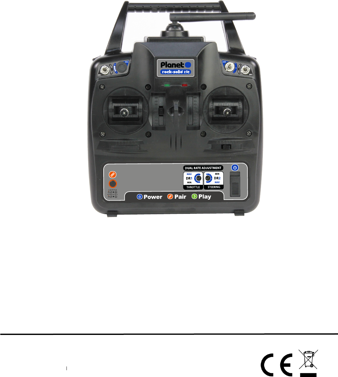
product Name: 4 CH 2.4GHZ FHSS RADIO CONTROL SYSTEM
Model Name: MT-403(Transmitter),MR-600( Receiver)
User Manual
1
2
3
4
56
78
10
11
12
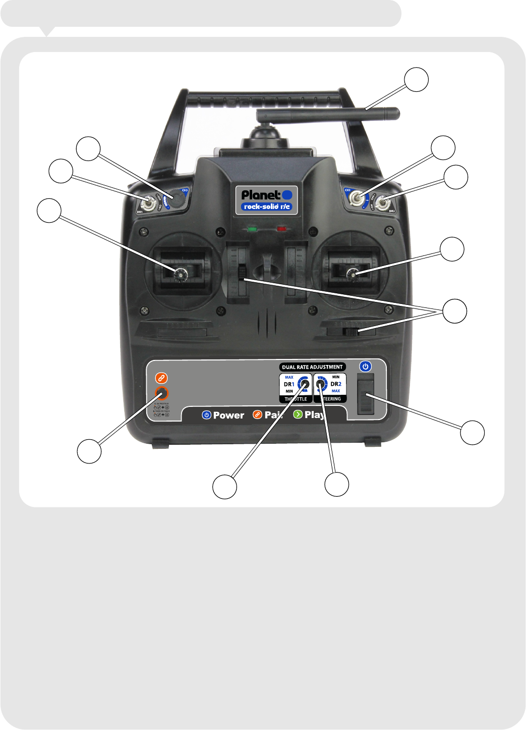
1. Channel 1 (right hand gimbal)
2. Channel 2 (left hand gimbal)
3. Channel 3 (3 position switch)
4. Channel 4 (variable dial)
5. Dual Rates switch for CH2
6. Dual Rates switch for CH1
7. Dual Rates adjustment for CH2
8. Dual Rates adjustment for CH1
9. Digital Trims and CH1/2 reverse
10. Pair button
11. Power switch
12. Folding aerial
9
Identify the transmitter’s features and function switches.
1
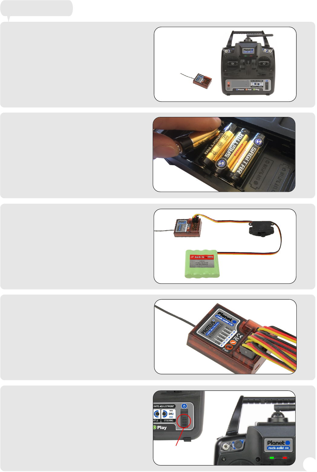
Remove the components from
the box and ensure you have the
following items:
Planet 2+2 transmitter (Tx)
Planet 6 channel receiver (Rx)
Remove the transmitter battery
cover and insert four AA alkaline
cells (not included)
Connect a fully charged 4.8V or 6V
battery to the receiver’s “BATT”
socket via a regular switch
harness. If you are connecting a
ESC with a BEC circuit this is to be
connected to CH2
Connect the servo leads to the
receiver channel outputs as
required. Active channel 1-4.
Turn on the transmitter by the
Power switch. The red Power LED
will illuminate. The transmitter will
emit a bleep which will then be
followed by the green LED
illuminating. The transmitter is now
searching for the receiver signal.
Getting started
Turn On
22
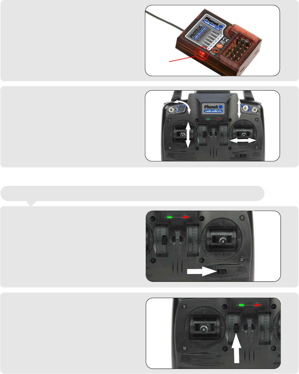
Turn on the receiver power and
note the receiver LED will
illuminate a solid red. This
indicates it has successful paired
with the transmitter.
Check all controls are working as
they should do. Move both sticks
to check for correct movement. If
the Aux 4 dial and Aux 3 channels
are connected test these as well
for correct operation.
To reverse CH1, power off the Tx.
Hold the trim on the right gimbal to
the right and turn the TX power
back on. Keep holding the over
until the green LED goes solid.
Release the trim button and check
for correct operation.
To reverse the servo back again
just repeat the process.
Servo Revers - The ability to reverse CH1 and CH2 servo directions.
LED
To reverse CH2, power off the Tx.
Hold the trim on the left gimbal up
and turn the TX power back on.
Keep holding the trim up until the
green LED goes solid. Release
the trim button and check for
correct operation.
To reverse the servo back again
just repeat the process.
3
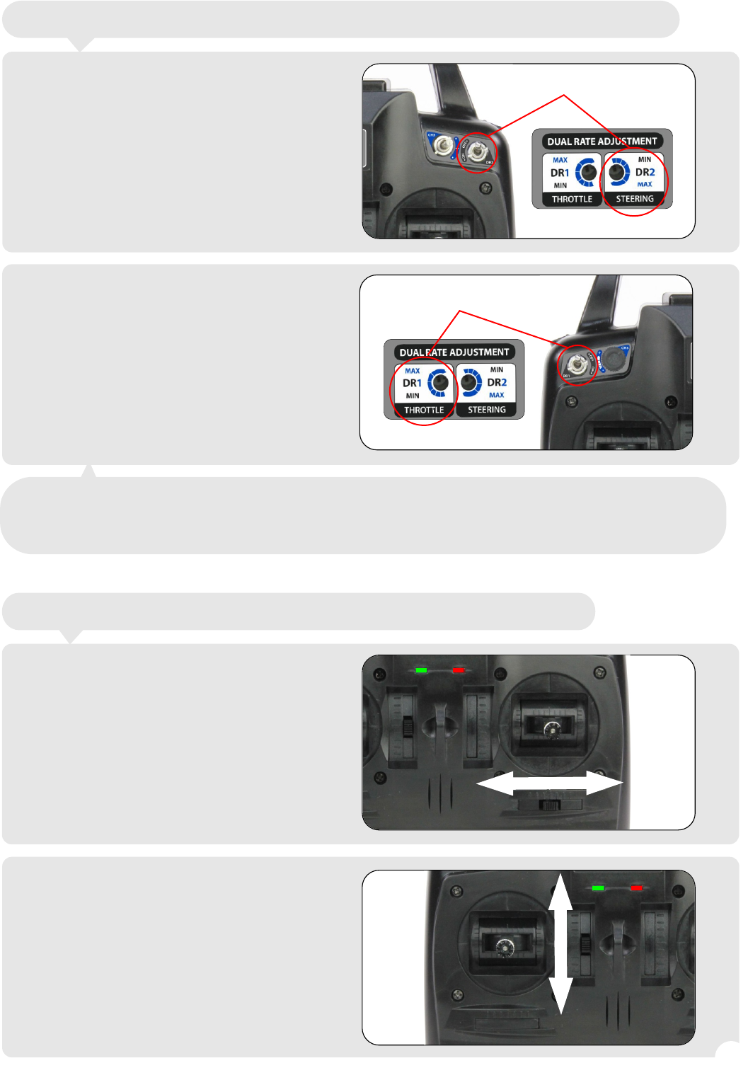
Adjusting CH1 D/R.
When the DR2 switch is in the off
position full travel is given to the
receiver CH1 servo output. When
the DR2 switch is in the On position
the travel of the servo is determine
by the position on the DR2 dial on
the dual rate adjuster panel.
Clockwise gives you more travel,
anti-clockwise gives you less.
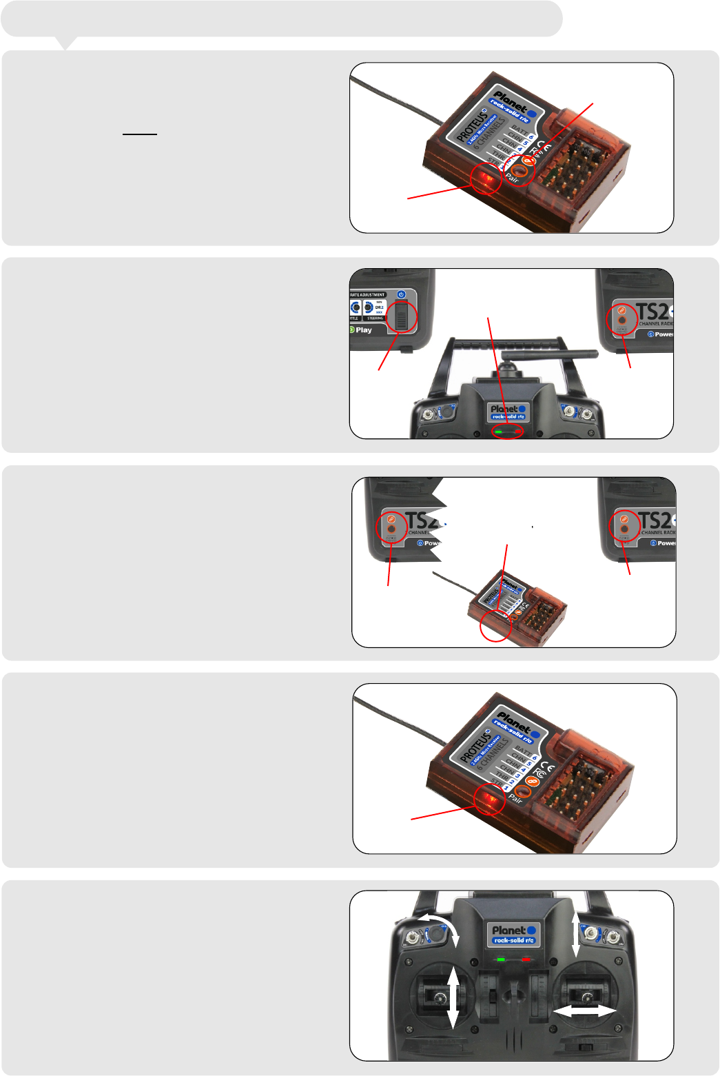
To adjust the centre point of the
receiver CH1 output, hold the trim
button on the right gimbal to the
left or the right as needed.
To adjust the centre point of the
receiver CH2 output, hold the trim
button on the left gimbal up or
down as needed.
Adjusting CH2 D/R.
When the DR1 switch is in the off
position full travel is given to the
receiver CH2 servo output. When
the DR1 switch is in the On position
the travel of the servo is determined
by the position on the DR2 dial on
the dual rate adjusting panel.
Clockwise gives you more travel,
anti-clockwise gives you less.
Trims - The ability to centre the servo outputs on CH1 and CH2
Dual Rates (D/R) - The ability to reduce the movement of CH1 and CH2
D/R AdjustmentD/R Adjustment
D/R Adjustment
Note - When using electronic ESCs on CH1 or CH2 it is essential that the
switches are in the Off position when powering the transmitter and the receiver.
This allows the ESCs to calibrate correctly.
44
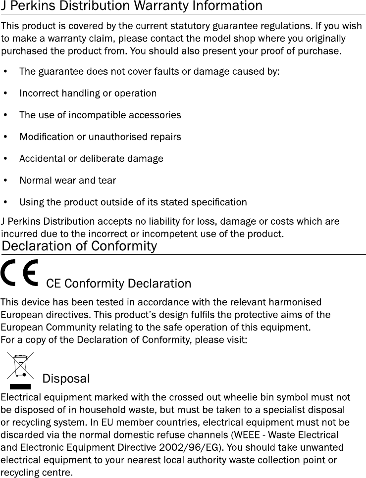
Pairing - The ability to connect the transmitter to the receiver.
To Pair a new or old receiver to
the transmitter, turn off the Tx
power. Press and hold the Pair
button on the receiver while
powering on the receiver. Once
power has been switched on
release the Pair button and the red
LED on the receiver will start to
flash. The receiver will stay in Pair
mode for 10 seconds.
Turn on the transmitter power.
As soon as the red and green
LEDs are illuminated press and
hold the Pair button.
LED
Pair button
Keep holding the transmitter Pair
button until the receiver LED is
extinguished. When the LED has
extinguished release the
transmitter Pair button.
Turn On Press
and
hold
Both LED`s
illuminated
Keep
pressing
LED
extinguishes
Release
pair
button
LED
solid red
The receiver LED should now
illuminate a solid red. You should
now have connection between
transmitter and receiver.
Check all controls are working as
they should do. Move both sticks
to check for correct movement. If
the Aux 4 dial and Aux 3 channels
are connected test these as well
for correct operation.
5
Distributed in the UK by:
J Perkins Distribution Ltd,
Lenham, Kent, ME17 2DL
United Kingdom
www.jperkins.com
6
FCC Statement
Any Changes or modifications not expressly approved by the party responsible for compliance
could void the user’s authority to operate the equipment.
This device complies with part 15 of the FCC Rules. Operation is subject to the following two
conditions:
(1) This device may not cause harmful interference, and
(2) This device must accept any interference received, including interference that may cause
undesired operation.
RF exposure statement :
This equipment complies with FCC radiation exposure limits set forth for an
uncontrolled environment .The device has been evaluated to meet general RF
exposure requirement. The device can be used in portable exposure condition with out
restriction.
The distance close to the finger usually should be 60mm.