MERIT TECHNOLOGY MT-602 6CH 2.4GHZ FHSS RADIO CONTROL SYSTEM User Manual

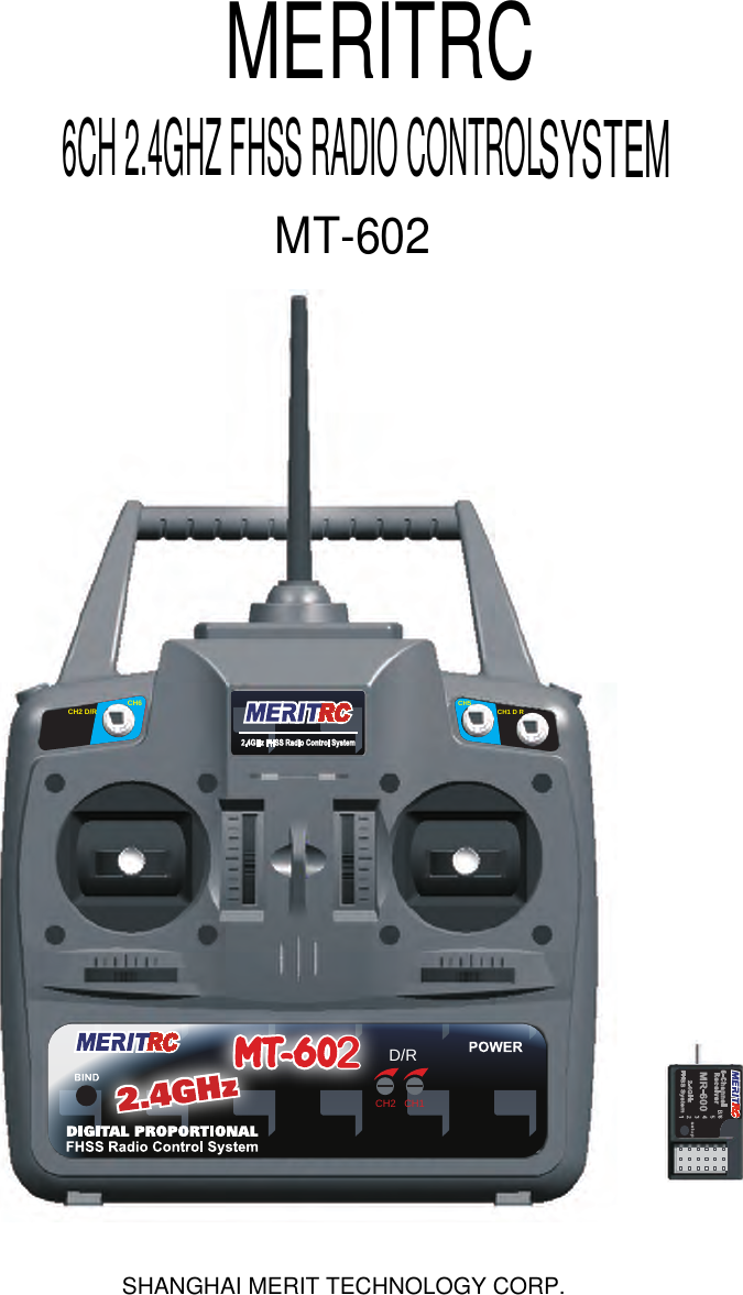
SHANGHAI MERIT TECHNOLOGY CORP. 6CH 2.4GHZ FHSS RADIO CONTROL SYSTEM

User manual

SYSTEMMERITRCCH2 D/R CH6CH5 CH1 D RCH2D/RCH16CH 2.4GHZ FHSS RADIO CONTROLMT-602SHANGHAI MERIT TECHNOLOGY CORP.
CH2 D R CH6CH5 CH1 D/RCH2D/RCH12CH1&CH2 D/R travelrange adjustment.CH2 D/RswitchBind buttonCH1 D/R SwitchUp position D/R-OFFDown Position D/R-ONand Function Mode.
This section describes the installation method and adjustment method after installa-tion when installing the receiver, servos, etc. to the plane.ConnectionsConnection example is shown below.(CH1)(CH2)(CH3)(CH4)(CH5)Flap Servo Gear Servo Rudder Servo Throttle Servo Elevator Servo Aileron Servo (CH6)ReceiverSwitchHarnessTo BatteryNOTE:NEVER use dry batteryas it cause malfunction.(The Y connector is sold separately)The diagram shown is for aircraft models only.Additional servos may have to be purchased separately.ADJUSTMENT AND INSTALLATION
TRANSMITTER MT-602 (Rear and Side Panel)""RECEIVERMR-600
Special notefor 2.4GHz FHSS radio system setupReceiver ’s Antenna installationSince the 2.4GHz have different characteristics than that of the conventional frequencies,please read this section carefully to enjoy safe flight with the 2.4GHz system.The wave length of the 2.4GHz is much shorter than that of the conventional frequencies,it is very susceptible to loss of signal which results inareceiving error.To obtain the best results,please refer to the following instructions;1. The antenna must be kept as straight as possible.Otherwise it will reduce theeffective range.2. The antenna should beperpendicular to the fuselage.Larger models can have largemetal objects that canattenuate the RF signal. In this case the antenna shouldbe placed at side of the model. Then the best RFsignal condition is obtained at any flying attitude.3. The antennamust be kept away from conductive materials, such as metal andcarbon by at leastahalf inch. The coaxial part of the antennas does not need tofollow these guidelines, but do not bend it inasmall radius.4. Keep the antenna away from the motor,ESC, and other noise sources as muchas possible.*The main purpose of the photodemonstrates how the antenna shouldbe placed. For actual installation thereceiver must be wrapped with asponge or placed with floating materialto protect it from vibration.180°The receiver contains precision electronic parts. It is the most delicate radiocomponent on-board the model and should be protected from vibration,shock and temperature extremes. To protect the receiver,wrap it in R/C foamrubber or other vibration-absorbing material. If appropriate, waterproof thereceiver by placing it inaplastic bag and closing the open end witharubberband before wrapping it in foam. If moisture enters the receiver,intermittentoperation orafailure may result. Wrapping the receiver inaplastic bag alsoprotects it from fuel and exhaust residue which, in some models, can work itsway into the fuselage.coaxial part
Transmitter antenna1. The transmitter antenna is adjustableso please make sure that the antenna isnever pointed directly at the modelwhen flying as this createsaweak signalfor the receiver.2. Keep the antenna perpendicular to thetransmitter's face to createabetter RFcondition for the receiver.Ofcoursethis depends on how you hold thetransmitter,but in most cases, adjustingthe transmitter antenna so that it is perpendicular to the face will give thebestresults. Please adjust the transmitter antenna to the way you hold thetransmitter.3. NEVER grip the antenna when flying as this degrades RF quality.
Binding Setup(Pair Procedure)Fail-Safe SetupProgramming a receiver to recognize the code of only one specific transmitter.Please note the setup must based on pair procedure well.1. Turn the power switch on the transmitter & receiver to the ON position,the     LED on transmitter & receiver are continuously lit. 2. Move the stick to the position where you want the servo to move, press and    hold the receiver setup button for 2 second until the red LED on the receiver     flash slowly, then press and hold the receiver setup button again within 5     seconds (Note: after 5 seconds F/S setup will reset, you have to start over     at step one above) until the receiver LED is continuously lit, that's mean the     F/S function has been correctly set.3.Verify if the failsafe function has been correctly set.Turn off the transmitter,   then check if the servos moves to the position that you set.4. Any new binding (pair procedure) will clear the preset Fail-Safe.1. Place the transmitter and the receiver close to each other (within one meter).     Turn the power switch on the transmitter to the ON position.2. Press and hold the receiver setup button,then turn the power switch to the     ON position. The receiver LED will flash quickly. Release the setup button     after 1 second.3. Press and hold the binding/PDM button on the transmitter for 1 second until    the green LED on the transmitter flash quickly then the LED on the transmi-    tter and receiver are continuously lit.If you change transmitters or add a receiver, you must re-bind before operating your model.Range check the radioA range check must be performed before the first flight of a new model.It is notnecessary to do a range check before every flight(but is not a bad idea to per-form a range check before the first flight of each day).A range check is the finalopportunity to reveal any radio malfunctions,and to be certain the system hasadequate operational range.1.We have installed a special “Power Down Mode” for doing a ground range    check.To activate the “Power Down Mode” please hold down the PDM  key    and then turn the transmitter switch on.During this mode,the RF power is    reduced so the range test can be performed.When this mode is active the   green LED starts blinking.In addition,when the mode is activated the trans-   mitter gives users a warning with a beep sound every 1 seconds,and visual   indication.
2.Walk away from the model while simultaneously operating the controls.Have   an assistant stand by the model and signal what the controls are doing to   confirm that they operate correctly.You should be able to walk approximately   30 - 50 paces from the model without losing control.3.If everything operates correctly,return to the model.Set the transmitter in a   safe,yet accessible location so it will be within reach after starting the engine.   Be certain the throttle stick is all the way down,then start the engine.Perform   another range check with your assistant holding the plane and the engine   running at various speeds.If the servos jitter or move inadvertently,there may   be a problem.Do not fly the plane!Look for loose servo connections or binding   pushrods.Also be certain that the battery has been fully charged.4.The “Power Down Mode” continues for 60 seconds and after that the power   will go back to the normal level.   To exit the “Power Down Mode” before the 60 seconds,turn the transmitter    switch on again.5.NEVER start flying when the “Power Down Mode” is active.The direction of movement for any of the four channels can be reversed electronically。To change the direction of movement for each main channel:1.Switch off the TX power switch。2.Press and hold one specific trim button for the channel to be reversed。CH1 right trim button for CH1 reversing.CH2 down trim button for CH2 reversing.CH3 high trim button for CH3 reversing.CH4 right trim button for CH4 reversing.3.Switch the TX power switch on,the GREEN LED should flash then steady on to indicate the movement for that channel has been reversed。 4.Repeat steps 1-3 to reverse the direction of any other channel as needed。SERVO REVERSING
The travel Range of the servos for the aileron or elevator can be changed at any time by using the switch marked CH1 D/R or CH2 D/R,located above the stick。With the switch in UP position,the channel’s servo will capable of rotating through its full travel range(100%)。Moving the switch to the opp--osite position(DOWN) will limit the rotational range of the channel’s servo。To adjust the D/R setting:1.Swith the D/R switch to the DOWN position。2.Adjust the trimmer located on the panel marked D/R CH1 or CH2,When the trimmer is turned counter-clockwise,the rotational range will decreases(Minimum 30%),conversely,the trimmer is turned clockwise,the rotational range will increases(Maximum 100%)。The Elevon and V-tail mixing functions which can be turned on or off 。Ele--von control consists of a mixture between the elevator and aileron channels。V-tail control consists of mixture between the elevator and rudder channels。The default setting for all mixing will be off the GREEN LED should be on steady。To change the mix setting:1.Switch off the TX power switch。2.Press and hold CH2 and CH3 DOWN&HIGH trim button simultaneously。3.Switch the TX power switch on,the GREEN LED should flash constantly to indicate the mixing function has been turned on。4.Repeat steps 1-3 to change the mixing function form Elevon on 、V-tail on then  off in sequence。CH1,CH2 DUAL RATE (D/R)ELEVON & V-TAIL MIXING FUNCTIONS
This function changes the stick mode of transmitter。Note:This will not change the throttle Ratchet etc。Those are mechanical changes that must be performed by specific technician。To change the MODE setting:1.Switch off the TX power switch。2.Press and hold CH1 and CH4 LEFT&RIGHT trim button simultaneously。3.Switch the TX power switch on,the GREEN LED should flash and acco--mpanied by two audible tones indicate the MODE 2 function has been tur--ned on。Conversely the GREEN LED flash and accompanied by one audi--ble tone indicate the MODE 1 function has been turned on。4.Repeat steps 1-3 to change the MODE function form MODE1 to MODE 2 in sequence。5.Since TX power switch on then accompanied by one audible tone indicate the MODE 1 function has been turned on,if accompanied by two audible tones indicate the MODE 2 function has been turned on。Intended for V-tail aircaft,V-tail mixingallows the ruddervators to operate bothas rudders and elevators.The same asthe other mixes,V-tail mixing requiresthat each ruddervator be operated by aseparate servo. *If necessary,use the Servo Reversingfunction to achieve the correct directionof servo throws.*If necessary,use the Servo Reversingfunction to achieve the correct directionof servo throws.V-tail MixingMODE 1、MODE 2 STICK SETTINGIntended for tailless,“flying wing” models suchas delta wings and flying wings,elevon mixingmixes channel 1 (aileron) to channel 2 (elevator) allowing the elevons to operate in unison(as elevators) or in opposition (as ailerons).This function requires that each elevon beoperated by a separate servo.Delta Wing MixingCH1 CH2
Transmitter Operation and Movement of Each ServoBefore making any adjustments, learn the operation of the transmitter and themovement of each servo. (In the following descriptions, the transmitter is assumedto be in the standby state.)AILERON OPERATIONWhen the aileron stick is moved to theright, the right aileron is raised and the leftaileron is lowered, relative to the directionof flight, and the plane turns to the right.When the aileron stick is moved to the left,the ailerons move in the opposite direction.To level the plane, the aileron stick mustbe moved in the opposite direction.When the aileron stick is tilted and held,the plane will roll.ELEVATOR OPERATIONWhen the elevator stick is pulled back, thetail elevator is raised and the tail of theplane is forced down, the air flow appliedto the wings is changed, the lifting force isincreased, and the plane climbs (UP opera-tion). When the elevator stick is pushedforward, the elevator is lowered, the tail ofthe plane is forced up, the air flow appliedto the wings is changed, the lifting force isdecreased, and the plane dives (DOWNoperation).THROTTLE OPERATIONWhen the throttle stick is pulled back, theengine throttle lever arm moves to theSLOW (low speed) side. When the throttlestick is pushed forward, the throttle leverarm moves to the HIGH (high speed) side.RUDDER OPERATIONWhen the rudder stick is moved to theright, the rudder moves to the right and thenose points to the right, relative to thedirection of flight. When the rudder stick ismoved to the left, the rudder moves to theleft and the nose points to the left and thedirection of travel of the plane changes.Elevator(CH2)Aileron(CH1)Throttle(CH3)Rudder(CH4)Right(Viewed from the rear)to the high speed side.Engine throttle lever movesto the low speed side.Left RightDown(Mode 1) (Mode 2)UpHighLow(Mode 1) (Mode 2)LeftLeft LightRightDown DownUp UpHigh HighLow LowLeft
WARNINGConnector ConnectionInsert the receiver,servo, andbattery connectors fully andfirmly.If vibration, etc. causes aconnector towork loose during flight, the plane maycrash.Receiver Vi brationpr oong/Waterpr oongVibrationproof the receiver bywrapping it in sponge rubber orsome such material. If the re-ceiver may get wet, waterproofit by placing it in a plastic bag.If the receiver is subjected to strong vibra-tion and shock, or gets wet, it may operateerroneously and causeacrash.Receiver AntennaDo not cut or bundle the re-ceiver antenna. Also, do notbundle the antenna togetherwith the servo lead wires.Cutting or bundling the receiver antennawill lower the receiver sensitivity andshorten the flight range and causeacrash.<Antenna installation>For aircraft, attach the antenna to the topofthe tail.Servo Thr owOperate each servo horn overits full stroke and adjust so thatthe pushrod does not bind or isnot too loose.Unreasonable force applied to the servohorn will adversely affect the servo anddrain the battery quickly.Servo InstallationInstall the servos to the servomount, etc. through arubbergrommet. Also install the servosso that the servo case does notdirectly touch the servo mountor other parts of the fuselage.Power Switch InstallationWhen installing areceiver power switch to thefuselage, cut arectangular hole somewhatlarger than the full stroke of the switch knoband install the switch so it moves smoothlyfrom ON to OFF.Also install the switch where it will not comeinto direct contact with engine oil, dust, etc.Generally,install the switch to the fuselage atthe side opposite the muffler exhaust.
FCC RF Exposure Information and Statement  This device complies with part 15 of the FCC rules. Operation is subject to the following two conditions: (1) this device may not cause harmful interference, and (2) this device must accept any interference received, including interference that may cause undesired operation. NOTE: The manufacturer is not responsible for any radio or TV interference caused by unauthorized modifications to this equipment. Such modifications could void the user’s authority to operate the equipment. NOTE: This equipment has been tested and found to comply with the limits for a Class B digital device, pursuant to part 15 of the FCC Rules. These limits are designed to provide reasonable protection against harmful interference in a residential installation. This equipment generates uses and can radiate radio frequency energy and, if not installed and used in accordance with the instructions, may cause harmful interference to radio communications. However, there is no guarantee that interference will not occur in a particular installation. If this equipment does cause harmful interference to radio or television reception, which can be determined by turning the equipment off and on, the user is encouraged to try to correct the interference by one or more of the following measures: - Reorient or relocate the receiving antenna. - Increase the separation between the equipment and receiver. -Connect the equipment into an outlet on a circuit different from that to which the receiver is connected. -Consult the dealer or an experienced radio/TV technician for help. This smartphone meets the government’s requirements for exposure to radio waves. The guidelines are based on standards that were developed by independent scientific organizations through periodic and thorough evaluation of scientific studies. The standards include a substantial safety margin designed to assure the safety of all persons regardless of age or health.  FCC RF Exposure information and Statement the SAR limit of USA (FCC) is 1.6W/kg averaged over one gram of tissue. Device type MT‐602 (FCC ID: XJ6MT-602) has also been tested against this SAR limit. SAR information on this and other pad can be viewed on-line at http://www.fcc.gov/oet/ea/fccid/To keep the device at least 0 mm away from your body to make sure the RF exposure level  compliant or lower to the reported level.   .The use of belt clips, holsters and similar accessories should not contain metallic components in its assembly. The use of accessories that do not satisfy these requirements may not comply with FCC RF exposure requirements, and should be avoided. changes or modifications not expressly approved by the party responsible for compliance could void the user's authority to operate the equipment.

Navigation menu