MERIT TECHNOLOGY MT600 6CH 2.4GHz FHSS Radio System User Manual 2 4G 6 1 eps
SHANGHAI MERIT TECHNOLOGY CORP. 6CH 2.4GHz FHSS Radio System 2 4G 6 1 eps
User Manual
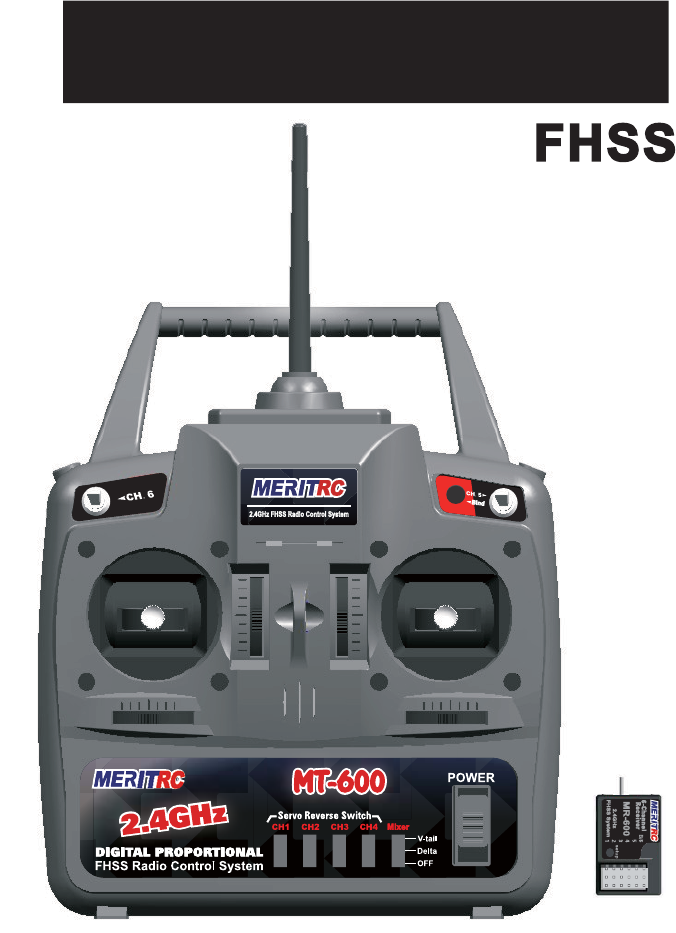
MT-600&MR-600
Radio
Radio S
ystem
ystem
Instruction
Instruction M
anual
anual
2.4GHz
2.4GHz
%LQGEXWWRQ
0L[HU
Used to electronically
change the on-board Mixer
options.Choose from OFF,
Delta,and V-tail.
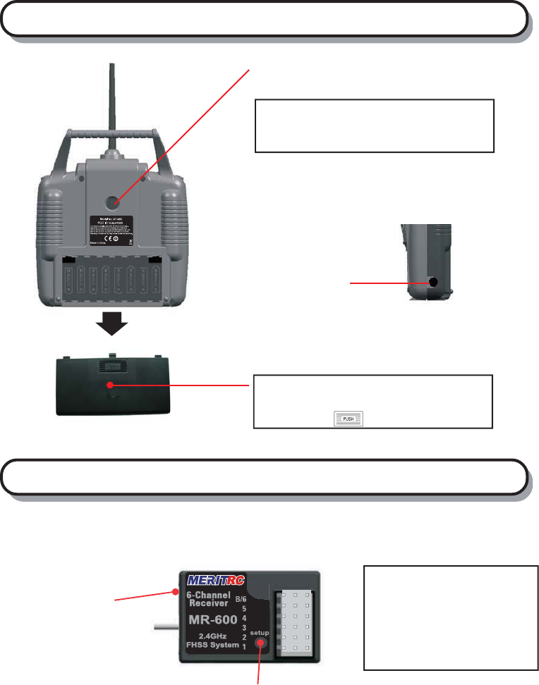
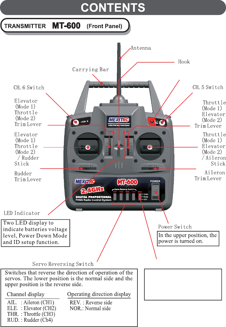
TRANSMITTER MT-600 (Rear and Side Panel)
Connects the trainer cord when using the
trainer function.
(The trainer cord is sold separately. )
Use when replacing the battery .
Slide the cover downward while pressing the
part marked " ".
Battery cover
Charging jack
Trainer jack
Antenna
Channel Output
"1": Aileron servo (CH1)
"2": Elevator servo (CH2)
"3": Throttle servo (CH3)
"4": Rudder servo (CH4)
"5": (Not used) (Ch5)
"6": (Not used) (CH6)
Pair button
(At side of box)
Link indicate LED
RECEIVER
Note:Merit MT-600 can only be the slave
if connect it with other brand radios.
MR-600
Special note for 2.4GHz FHSS radio system setup
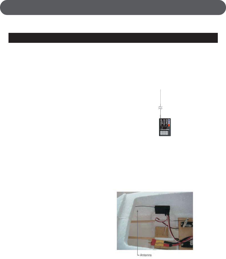
Receiver ’s Antenna installation
Since the 2.4GHz have different characteristics than that of the conventional frequencies,
please read this section carefully to enjoy safe flight with the 2.4GHz system.
The MR-600 has two antennas. These antennas have a diversity function to decrease the
chance of a receiving error.
The wavelength of the 2.4GHz is much shorter than that of the conventional frequencies,
it is very susceptible to loss of signal which results in a receiving error. In order to avoid
this phenomenon, the MR-600 adopted a diversity antenna system.
To obtain the best results of the diversity function, please refer to the following
instructions;
1. The two antennas must be kept as straight as
possible. Otherwise it will reduce the effective
range.
2. The two antennas should be placed at 90 degrees
to each other. This is not a critical figure, but the
most important thing is to keep the antennas away
from each other as much as possible. Larger models can have large metal objects
that can attenuate the RF signal. In this case the antennas should be placed at both
sides of the model. Then the best RF signal condition is obtained at any flying attitude.
3. The antennas must be kept away from conductive materials, such as metal and carbon
by at least a half inch. The coaxial part of the antennas does not need to follow these
guidelines, but do not bend it in a small radius.
4. Keep the antennas away from the motor, ESC, and other noise sources as much
as possible.
* The two antennas should be placed at
90 degrees to each other.
* The main purpose of the photo
demonstrates how the antenna should
be placed. For actual installation the
receiver must be wrapped with a
sponge or placed with floating material
to protect it from vibration.
e
The receiver contains precision electronic parts. It is the most delicate radio
component on-board the model and should be protected from vibration,
shock and temperature extremes. To protect the receiver, wrap it in R/C foam
rubber or other vibration-absorbing material. If appropriate, waterproof the
receiver by placing it in a plastic bag and closing the open end with a rubber
band before wrapping it in foam. If moisture enters the receiver, intermittent
operation or a failure may result. Wrapping the receiver in a plastic bag also
protects it from fuel and exhaust residue which, in some models, can work its
way into the fuselage.
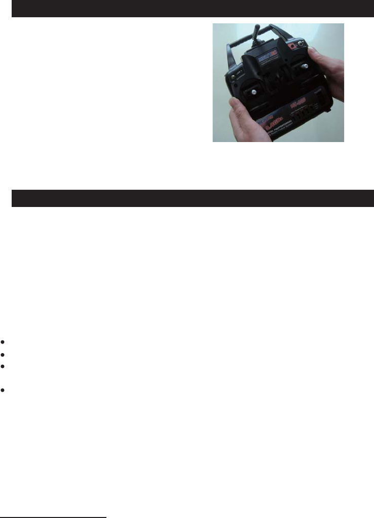
Transmitter antenna
1. The transmitter antenna is adjustable
so please make sure that the antenna is
never pointed directly at the model
when flying as this creates a weak signal
for the receiver.
2. Keep the antenna perpendicular to the
transmitter's face to create a better RF
condition for the receiver. Of course
this depends on how you hold the
transmitter, but in most cases, adjusting
the transmitter antenna so that it is perpendicular to the face will give the best
results. Please adjust the transmitter antenna to the way you hold the transmitter.
3. NEVER grip the antenna when flying as this degrades RF quality.
FCC Compliance Statement
This equipment has been tested and found to comply with the limits for a Class
B digital device, pursuant to Part 15 of the FCC Rules. These limits are designed
to provide reasonable protection against harmful interference in a residential
installation. This equipment generates, uses, and can radiate radio frequency
energy and, if not installed and used in accordance with the operating instructions,
may cause harmful interference to radio communications, however, there is no
guarantee that interference will not occur in a particular installation. If this
equipment does cause harmful interference to radio or television reception, which
can be determined by turning the equipment off and on, the user is encouraged to
correct the interference by one or more of the following measures:
Reorient or relocate the receiving antenna.
Increase the separation between the equipment and the receiver.
Connect the equipment into an outlet on a circuit different from that to which
the receiver is connected.
Consult the dealer or an experienced technician for help.
This device complies with Part 15 of the FCC Rules and with RSS-210 of
Industry Canada.Operation is subject to the following two conditions:
1)This device may not cause harmful interference, and....
2)This device must accept any interference received, including interference that
may cause undesired operation.
WARNING:Changes or modifications made to this equipment not expressly
approved by the party responsible for compliance may void the FCC authorization
to operate this equipment.
Fail Safe Setup , Continue...
4. To confirm that fail safe is working properly, the ESC will go in to the neutral
position and the vehicle will not move when you shut off the transmitter. See
page 5 and check the Fail Safe function working properly. You do not need to
repeat this procedure each time you run.
5. To confirm that fail safe is working properly, full brake should automatically be
applied when you shut off the transmitter. See page 5 and check the Fail Safe
function working properly. You do not need to repeat this procedure each time
you run.
Turn off receiver first, then turn off transmitter.
Binding Setup
Fail Safe Setup
Programming a receiver to recognize the code of only one specitic transmitter.
The fail safe system has been setup at the factory,but you should become
familiar with the function of the fail safe and check the operation before
running. When fail safe is operating,the red LED will continuously flash.
1. Place the transmitter and the receiver close to each other (within one meter).
Turn the power switch on the transmitter to the ON position.
2. Press and hold the receiver setup button,then turn the power switch to the ON
position. The receiver LED will flash quickly. Release the setup button after
1 second.
3. Press and hold the binding button on the transmitter for 1 second until the
LED on the receiver is continuously lit.
1. Turn the power switch to the ON position on the transmitter. Press the setup
button on the receiver then release. LED will flash.
2. Leave throttle trigger in neutral position, and press the setup button. The LED
will flash quickly.Once the receiver LED remains lit, then release the setup
button on the receiver.
3. Hold full brake on the transmitter, and press the setup button. The LED will
flash quickly. Release full brake on the transmitter once the receiver LED
remains lit, then release the setup button on the receiver.
If you change transmitters or add a receiver, you must re-bind
before operating your vehicle.
The fail safe can not completely protect your car.
Any new binding of transmitter & receiver will clear the preset
fail safe.

The transmitter has a individual randomize ID that is created in the factory, Even it is
almost have no chance to meet the same ID transmitter in the same fly field,
he transmitter has an ID set up function.
You can go back to the original factory set ID by h
in case it does
happen. T
olding the “PDM” when turn on the
transmitter, without press the “PDM” bottom, turn it off and on again to get back the
original ID.
Change the transmitter ID
Range check the radio
A range check must be performed before the first flight of a new model. It is not necessary
to do a range check before every flight (but is not a bad idea to perform a range check
before the first flight of each day). A range check is the final opportunity to reveal any
radio malfunctions, and to be certain the system has adequate operational range.
1. There is "Power Down Mode" build in for doing a ground range check To activate the
"Power Down Mode" by pressing the “PDM” button on the right upper panel of the
transmitter. The Green LED will turn off to indicate the PDM is working. During this
mode, the RF power is reduced so the range test can be performed.
2. Walk away from the model while simultaneously operating the controls. Have an
assistant stand by the model and signal what the controls are doing to confirm that
they operate correctly. You should be able to walk 30 - 50 paces approximately from
the model without losing control.
3. If everything operates correctly, return to the model. The "Power Down Mode"
continues for 60 seconds and after that the power will go back to the normal level.
To exit the "Power Down Mode" before the 60 seconds, press the "PDM" key again.
4. NEVER start flying when the "Power Down Mode" is active.
Transmitter Operation and Movement of Each Servo
Before making any adjustments, learn the operation of the transmitter and the
movement of each servo. (In the following descriptions, the transmitter is assumed
to be in the standby state.)
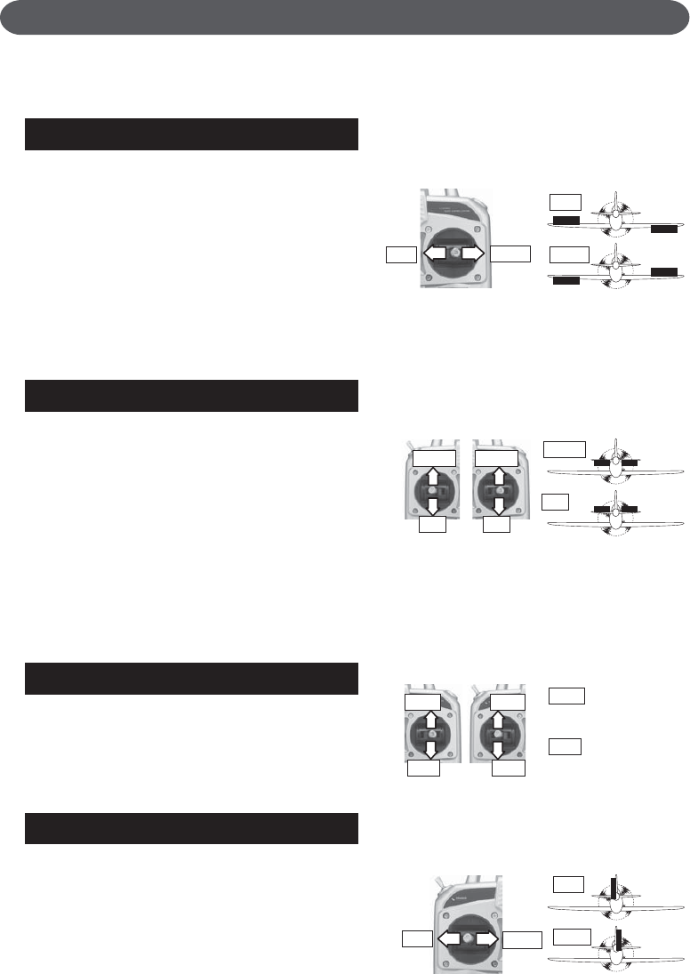
AILERON OPERA TION
When the aileron stick is moved to the
right, the right aileron is raised and the left
aileron is lowered, relative to the direction
of flight, and the plane turns to the right.
When the aileron stick is moved to the left,
the ailerons move in the opposite direction.
To level the plane, the aileron stick must
be moved in the opposite direction.
When the aileron stick is tilted and held,
the plane will roll.
ELEVATOR OPERA TION
When the elevator stick is pulled back, the
tail elevator is raised and the tail of the
plane is forced down, the air flow applied
to the wings is changed, the lifting force is
increased, and the plane climbs (UP opera-
tion). When the elevator stick is pushed
forward, the elevator is lowered, the tail of
the plane is forced up, the air flow applied
to the wings is changed, the lifting force is
decreased, and the plane dives (DOWN
operation).
THROTTLE OPERA TION
When the throttle stick is pulled back, the
engine throttle lever arm moves to the
SLOW (low speed) side. When the throttle
stick is pushed forward, the throttle lever
arm moves to the HIGH (high speed) side.
RUDDER OPERA TION
When the rudder stick is moved to the
right, the rudder moves to the right and the
nose points to the right, relative to the
direction of flight. When the rudder stick is
moved to the left, the rudder moves to the
left and the nose points to the left and the
direction of travel of the plane changes.
Elevator(ch2)
Aileron(ch1)
Thr ottle(ch3)
Right
(Viewed from the rear)
Engine throttle lever moves
to the high speed side.
Engine throttle lever moves
to the low speed side.
Left Right
Down
(Mode 1) (Mode 2)
Up
High
Low
(Mode 1) (Mode 2)
Left
Left Light
Right
Down Down
Up Up
High High
Low Low
Left
This section describes the installation method and adjustment method after installa-
tion when installing the receiver, servos, etc. to the plane.
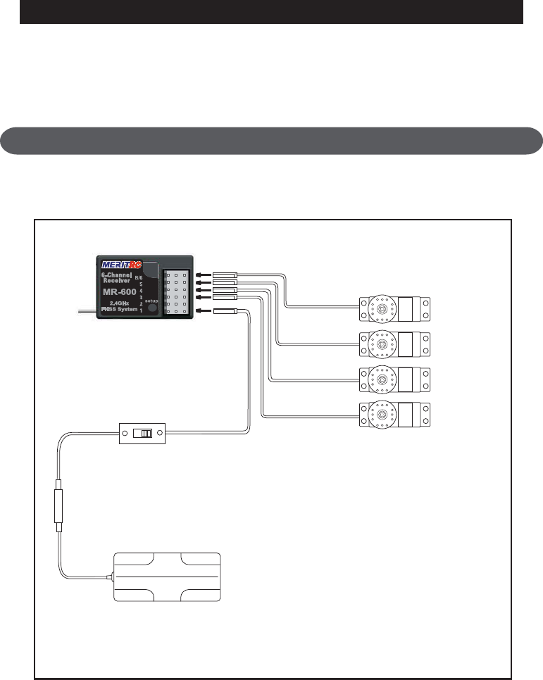
Connections
Connection example is shown below.
ADJUSTMENT AND INSTALLATION
Connection Example
Receiver
MR-600
Aileron
(CH1)
Elevator
(CH2)
Thr ottle
(CH3)
Rudder
(CH4)
Receiver switch
Receiver battery holder
*Insert four batteries.
*When using 5 or more servos,
use the nicd battery sold separately.
*The number of servos depends
on the set.
WARNING
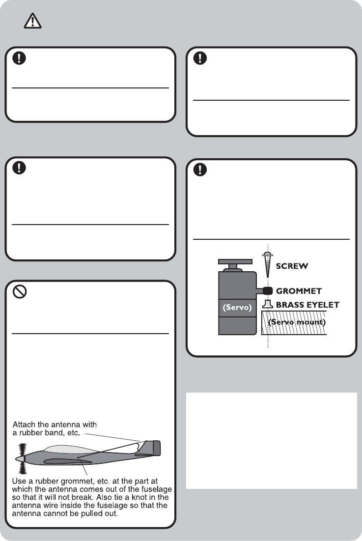
Connector Connection
Insert the receiver, servo, and
battery connectors fully and
firmly.
If vibration, etc. causes a connector to
work loose during flight, the plane may
crash.
Receiver Vibrationpr oofing
/ Waterpr oofing
Vibrationproof the receiver by
wrapping it in sponge rubber or
some such material. If the re-
ceiver may get wet, waterproof
it by placing it in a plastic bag.
If the receiver is subjected to strong vibra-
tion and shock, or gets wet, it may operate
erroneously and cause a crash.
Receiver Antenna
Do not cut or bundle the re-
ceiver antenna. Also, do not
bundle the antenna together
with the servo lead wires.
Cutting or bundling the receiver antenna
will lower the receiver sensitivity and
shorten the flight range and cause a crash.
<Antenna installation>
For aircraft, attach the antenna to the top of
the tail.
Servo Thr ow
Operate each servo horn over
its full stroke and adjust so that
the pushrod does not bind or is
not too loose.
Unreasonable force applied to the servo
horn will adversely affect the servo and
drain the battery quickly.
Servo Installation
Install the servos to the servo
mount, etc. through a rubber
grommet. Also install the servos
so that the servo case does not
directly touch the servo mount
or other parts of the fuselage.
Power Switch Installation
When installing a receiver power switch to the
fuselage, cut a rectangular hole somewhat
larger than the full stroke of the switch knob
and install the switch so it moves smoothly
from ON to OFF.
Also install the switch where it will not come
into direct contact with engine oil, dust, etc.
Generally, install the switch to the fuselage at
the side opposite the muffler exhaust.
The operating dir ection, neutral position, and steering angle of each servo ar e adjusted.
CAUTION
The basic linkage and adjustments of the fuselage conform to the fuse-
lage design drawings and kit instruction manual. Be sure that the center
of gravity is at the prescribed position.
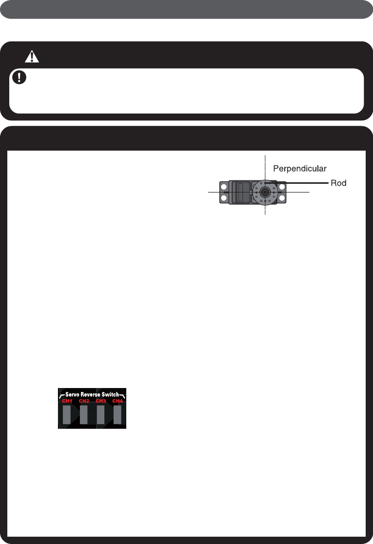
Adjustment Pr ocedur e
Before making any adjustments, set
all the SERVO REVERSER switches
on the front of the transmitter to the
lower (NOR) position. (Switch the
switches with a small screwdriver,
etc.)
Turn on the transmitter and receiver
power switches and make the follow-
ing adjustments:
1Check the dir ection of opera-
tion of each servo.
If a servo operates in the wrong direction,
switch its SERVO REVERSER switch. (The
direction of operation can be changed without
changing the linkage.)
*Note that the direction of the aileron servo is
easily mistaken. (Page 10)
2Check the aileron, elevator ,
and rudder neutral adjustment
and left-right (up-down) thr ow.
Check that when trimmed to the center, the
servo horn is perpendicular to the servo and
check the neutral position of the fuselage
control surfaces (aileron, elevator, rudder,
etc.). If the neutral position has changed, reset
it by adjusting the length of the rod with the
linkage rod adjuster.
When the throw is unsuitable (different from
steering angle specified by the kit instruction
manual), adjust it by changing the servo horn
and each control surface horn rod .
3Check the engine thr ottle
(speed adjustment) linkage.
Change the servo horn installation position
and hole position so that the throttle is opened
fully when the throttle stick is set to HIGH
(forward) and is closed fully when the throttle
stick and throttle trim are set for maximum
slow (backward position and lower position,
respectively).
4After all the linkages have
been connected, recheck the
operating dir ection, thr ow, etc.
*Before flight, adjust the aircraft in accor-
dance with the kit and engine instruction
manuals.
5Fly the plane and trim each
servo.
Adjustments