MERIT TECHNOLOGY T2HF 2.4GHz RADIO SYSTEM User Manual
SHANGHAI MERIT TECHNOLOGY CORP. 2.4GHz RADIO SYSTEM Users Manual
Users Manual
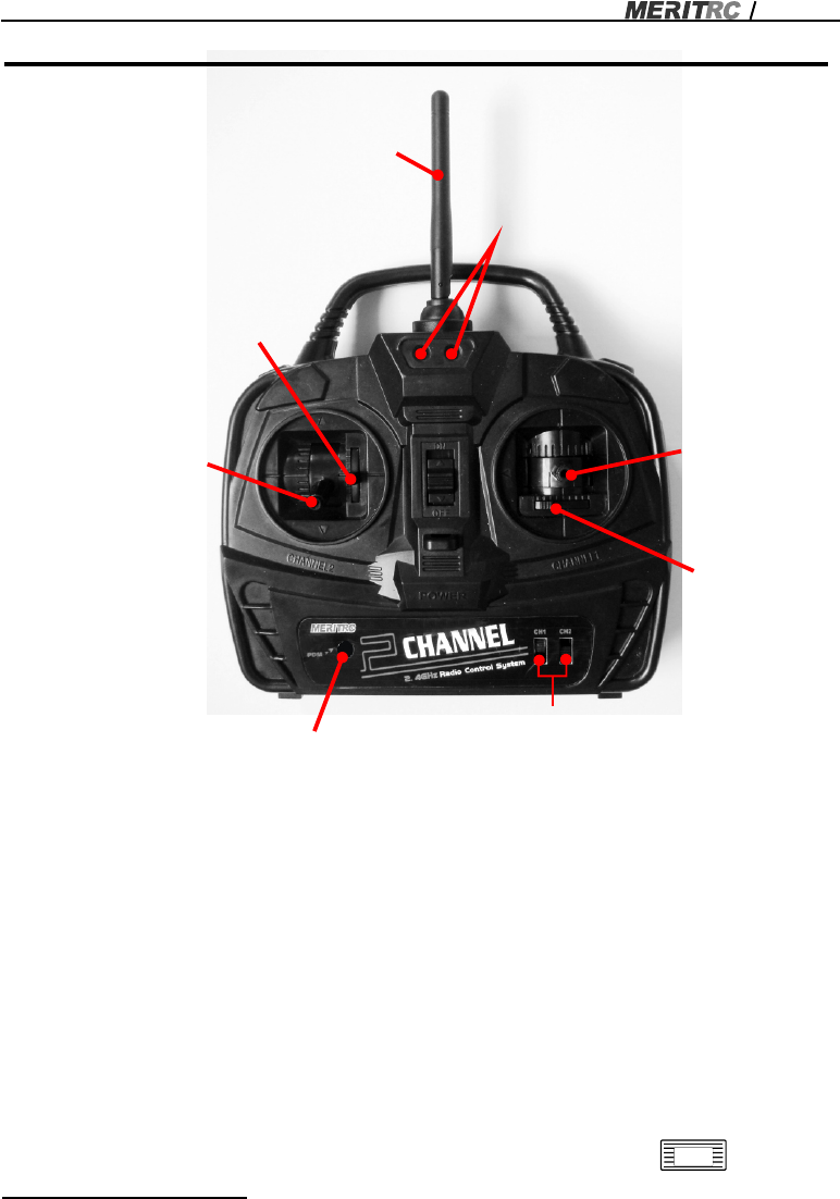
LED Indicator
SAIL TRIM
SAIL
STICK
Power down mode
( PDM ) BUTTON
ANTENNA
RUDDER
STICK
RUDDER
TRIM
SERVO REVERSE SWITCHES
MERMAID
MERMAID Instruction Manual
2CH 2.4GHz RADIO SYSTEM INSTRUCTION (T2HF)
LED INDICATOR LIGHTS
Two LEDs display to indicate the battery voltage level, power down mode and ID
set up function.
SERVO REVERSE SWITCHES
Servo reverse switches reverse the direction of the operation of the servos. The lower
position is normal and upper position is reverse.
CHANNELS:
CH1: Rudder
CH2: Sail
REAR PANNEL
The transmitter needs 8 AA batteries (sold separately). To open the battery
compartment slide the cover down while pressing the part marked: PUSH
MERMAID
MERMAID Instruction Manual
2
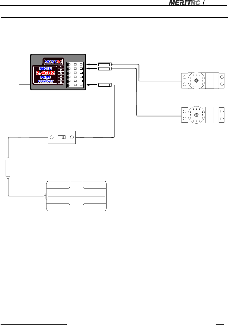
CONNECTIONS
Connection example is shown below.
Connection Example
2.4GHz systems have different characteristics than that of the conventional
frequencies therefore ,please read the section carefully to enjoy safe sailing with the
2.4GHz systems.
2.4GHZ FHSS RADIO SYSTEM SETUP
LED
Receiver
R601SF
Receiver Switch
* Insert four batteries.
Receiver battery holder
Rudder Servo
(CH1)
Sail Servo
(CH2)
MERMAID
MERMAID Instruction Manual
3
TRANSMITTER ANTENNA
1. The transmitter antenna is adjustable so please make sure that the antenna is
never pointed directly at the boat when sailing as this creates a week signal for
the receiver.
2. Keep the antenna perpendicular to the transmitter's face to create a better RF
condition for the receiver. Of course this depends on how you hold the transmitter,
but in most cases, adjusting the transmitter antenna so that it is perpendicular to
the face will give the best results. Please adjust transmitter antenna to the way
you hold the transmitter.
PAIR PROCEDURE
The transmitter has an individual ID that is assigned to it in the factory. In order to
start operation, the receiver must be linked with the Id code of the transmitter with
which it is being paired. Once the link is made, the ID code is stored in the receiver
and no further linking is necessary unless he receiver is to be used with another
transmitter. If you purchase another MERITRC receiver this procedure is necessary,
otherwise the receiver will not work.
The receiver contains precision electronic parts. It is the most delicate radio
component on-board the boat and should be protected from vibration, shock and
temperature extremes .To protect the receiver, wrap it in R/Cfoam rubber or other
vibration-absorbing material. If appropriate, waterproof the receiver by placing it in a
plastic bag and closing the open band with a rubber before wrapping it in foam .If
moisture enters the receiver, intermittent operation or a failure may result.
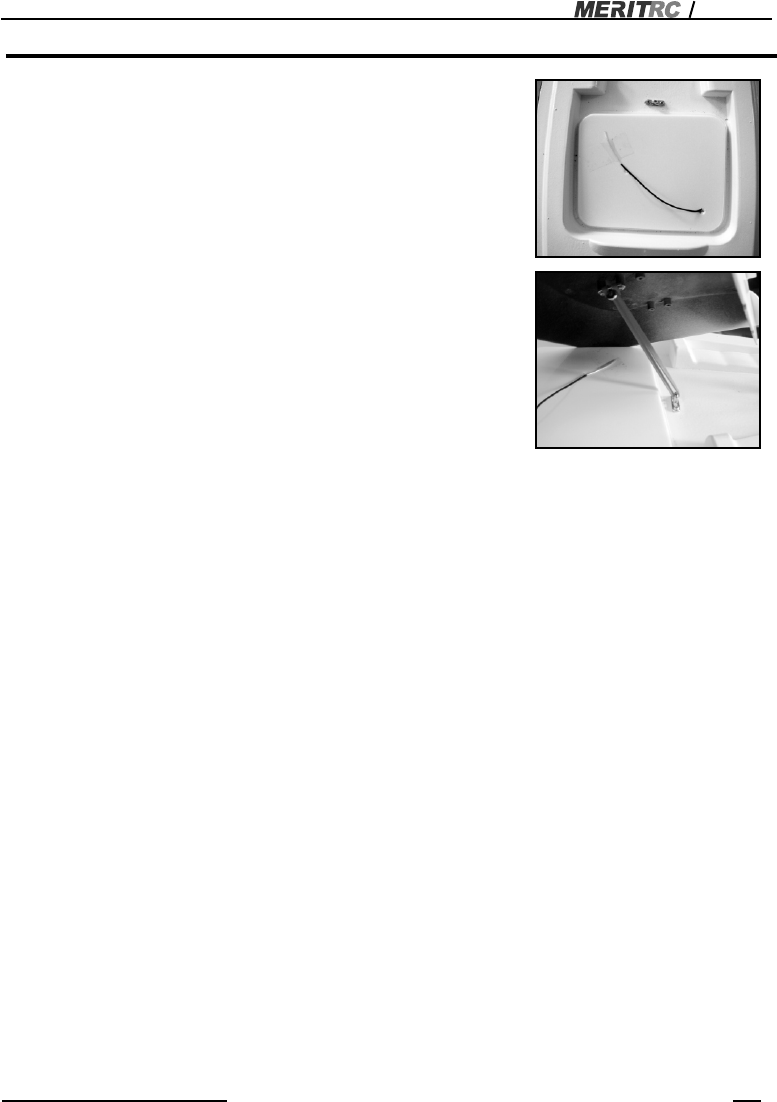
RECEIVER ANTENNA INSTALLATION
The receiver has one antenna.
Lay & tape the antenna on the hatch seal as shown .
1. The antenna must be kept away from conductive
material ,such as material and carbon by at least
half an inch. The coaxial part of the antenna does
not need to follow these guidelines ,but don't bend
it in a small radius.
2. Keep the antenna away from any noise sources
as much as possible.
3. Cover the hatch cover with rubber band.
This photo demonstrates how the antennas should
be placed .For actual installation the receiver must
be wrapped in anti-vibration foam to protect it from
vibration damage.

MERMAID
MERMAID Instruction Manual
4
Please refer to the table below for the LED status indicating the receiver condition.
Receiving signals an ID is matched: ON
Receiving signals, but ID is not matched: Off
No signal reception: Off
Receiver ID memory is empty: Blink slowly.
To keep the receiver and transmitter pairing memory, turn off the transmitter after
above procedures. then turn on again. Now, the transmitter and receiver can talk to
each other smoothly.
1. Place the transmitter and receiver close to each other (with 1 meter).
2. Turn on the transmitter then the receiver. If they are not paired, the read LED on
the receiver will blink slowly or be off, follow the next steps to link and pair the
receiver and the transmitter.
3. Press the transmitter “PDM” switch, the two LEDs blink alternately, then releaset
the switch. Turn on the receiver power, then press down the receiver “pair button”
switch for more than two seconds, once paired the receiver LED will start to blink
quickly, it shows they are pared, release the switch.
4. Press the transmitter “PDM” button again, when the linkage is complete, the
receiver LED will change to solid read and receiver will start to respond to the
transmitter after 2 seconds.

MERMAID
MERMAID Instruction Manual
5
This equipment has been tested. And it found to comply with the limits for a Class B
digital device pursuant to Part 15 of the FCC Rules. These limits are designed to
provide reasonable protection against harmful interference in a residential installation.
This equipment generates and uses and radiates radio frequency energy and, if not
installed and used in accordance with the instruction, may cause harmful interference
to radio communications. However, there is no guarantee that interference will not
occur in a particular installation. If this equipment does cause harmful interference to
radio or television reception, which can be determined by turning the equipment off
and on, the user is encouraged to try to correct the interference by one or more of the
following measures:
-Reorient or relocate the receiving antenna.
-Increase the separation between the equipment and receiver.
-Connect the equipment into an outlet on a circuit different from that to which the
receiver is connected
-Consult the dealer or an experienced radio /TV technician for help.
Warning: A shielded-type power cord is required in order to meet FCC emission limits
and also to prevent interference to the nearby radio and television reception. It is
essential that only the supplied power cord be used.
1. This device complies with Part 15 of the FCC Rules. Operation is subject to the
following two conditions: (1) This device may not cause harmful interference, and
(2) This device must accept any interference received, including interference that may
cause undesired operation.
2. Changes or modifications not expressly approved by the party responsible for
compliance could void the user's authority to operate the equipment.
This device complies with Part 15 of the FCC Rules. Operation is subject to the
following two conditions:
(1)This device may not cause harmful interference, and
(2)This device must accept any interference receive,including interference that
may cause undesired operation.
Federal Communications Commission (FCC) Statement

1058 Taogan Road, Sheshan, Songjiang district,
Shanghai, China 201602
Tel: 86-21-57793858