MERIT TECHNOLOGY TXT3HFMR 2.4GHz RADIO CONTROL SYSTEM User Manual 2 4G Pistol controller 2009 09 08
SHANGHAI MERIT TECHNOLOGY CORP. 2.4GHz RADIO CONTROL SYSTEM 2 4G Pistol controller 2009 09 08
Users Manual
RR
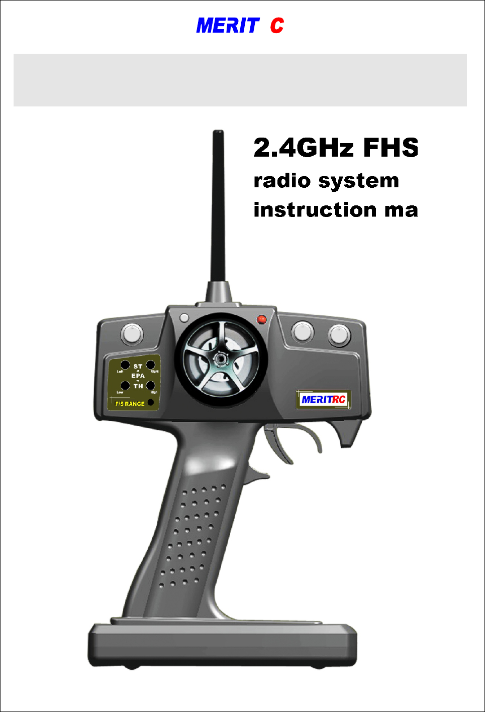
2.4GHz FHSS
radio system
instruction manual
2.4GHz Pistol Radio Set
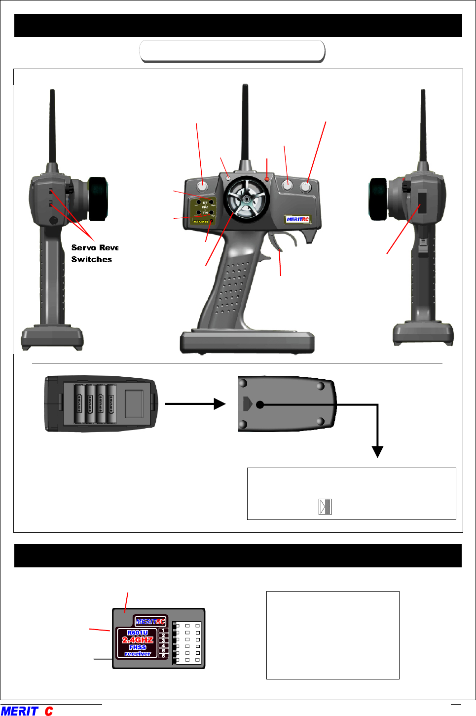
NAME OF EACH PARTNAME OF EACH PART
TRANSMITTER
BATTERY COVER
When replacing the battery.
Slide the cover downward while pressing the
part marked “ ”.
Servo Reverse
Switches
On/off Switch
RR
RECEIVER
LED
Link indicate LED
Pair button
(At side of box)
Antenna
CHANNEL OUTPUT
"1": CH1
"2": CH2
"3": CH3
"4": CH4
"5": (Not used)(CH5)
"6": (Not used)(CH6)
* Please noted the transmitter does not
have charging function, 4"AA” alkaline
dry cells required. ..
2
Throttle Trim Knob
(CH3)
Switch
"PDM"
Button
Steering Wheel
Throttle Trigger
LED
Dual Rate Knob
Steering Trim Knob
(CH.1)EPA
(CH.2)EPA
Spectial note for 2.4GHz FHSS radio system setup
Since the 2.4GHz have different characteristics than that of the conventional frequencies, please read
this section carefully to enjoy safe flight with the 2.4GHz system.
The wavelength of the 2.4GHz is much shorter than that of the conventional frequencies, it is very
susceptible to loss of signal which results in a receiving error. In order to avoid this phenomenon,
please must follow the receiver antenna installation shown as below.
. .
Receiver’s Antenna Installation
RR
3
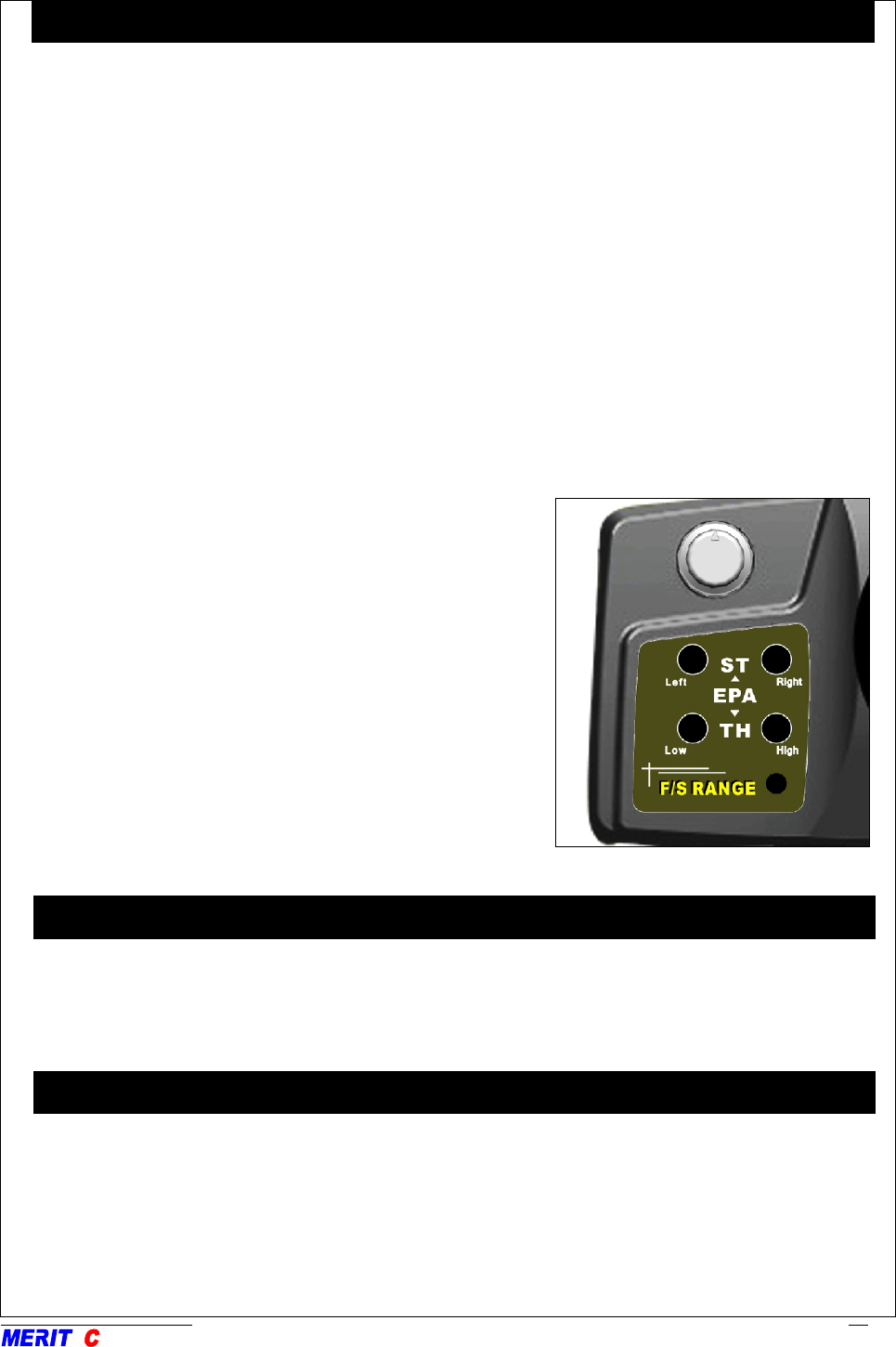
Use this when performing left and right steering angle adjustments, throttle high side/brake side
operation amount adjustment. - Corrects the maximum steering angle and left and right steering
angles when there is a difference in the turning radius due to the characteristics, etc. of the vehicle.
Maximum steering angle adjustment
(The EPA function basically determines the maximum steering angle of each channel in each direction.)
Adjustment: Range: 75~125% of each direction.
Use the small Philip screwdriver (+) to turn the two small knobs inside the control panel upper side as
shown to make adjustments of the steering angle of each direction. (Caution: The servo reverse
switches will effect to the directions)
Caution!
Decide the EPA value at the contact point of your vehicle steering system construction. When trim the
EPA, be sure that the steering servo does not bind at the maximum steering angle.
Throttle (forward, brake side/reverse side) adjustment.
Adjustment: Range: 75~125% of each direction.
Use the small Philip screwdriver (+) to turn the two small
knobs inside the control panel lower side as shown to
make adjustments of the control range of each direction.
(Caution: The servo reverse switches will effect to the
directions)
Caution!
If the throttle channel is connected to an ESC, read your
ESC manual to decide the EPA value for your vehicle.
End Point Adjustment / EPA
RR
4
1. The antenna must be kept as straight up as possible.
Otherwise it will reduce the effective range.
2. The antenna should be placed at 90 degrees to
the receiver case.
3. The antenna must be kept away from conductive materials, such as metal and carbon by at least a
half inch. The coaxial part of the antennas does not need to follow these guidelines, but do not bend
it in a small radius.
4. Keep the antenna away from the motor, ESC, and other noise sources as much as possible.
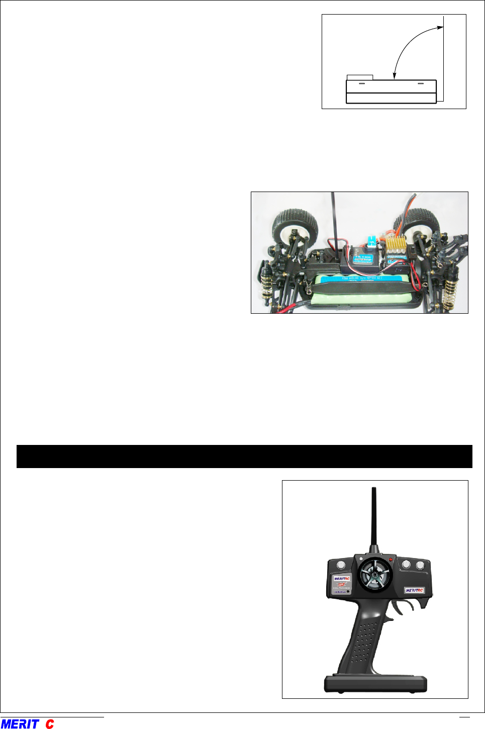
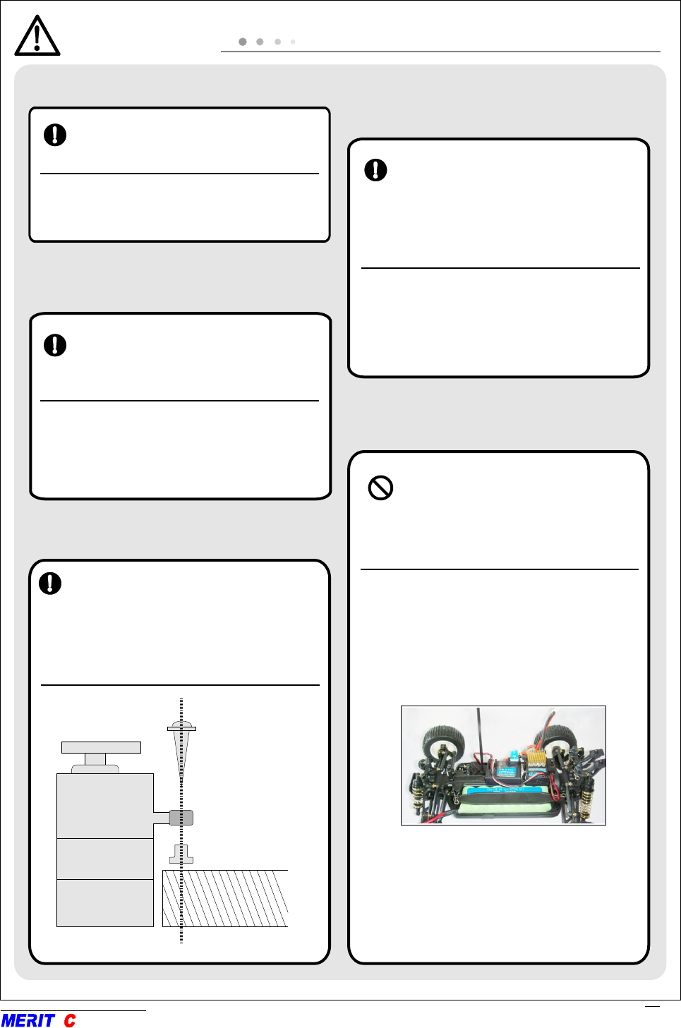
*This photo demonstrates how the antenna
should be placed. For actual installation the
receiver must be wrapped with a sponge
or placed with floating material to protect
it from vibration .
The receiver contains precision electronic parts. It is the most delicate radio component on-board the
model and should be protected from vibration, shock and temperature extremes. To protect the receiver,
wrap it in R/C foam rubber or other vibration-absorbing material. If appropriate, waterproof the receiver
by placing it in a plastic bag and closing the open end with a rubber band before wrapping it on chassis.
If moisture enters the receiver, intermittent operation or a failure may result. Wrapping the receiver in a
plastic bag also protects it from fuel and exhaust residue which, in some cars, can work its way into the
body. . .
Transmitter Antenna
1. The transmitter antenna is adjustable so please
make sure the antenna is never pointed directly
at the model when running it as this creates a
weak signal for the receiver.
2. Keep the antenna vertical to the ground to create
a better RF condition for the receiver. Of course
this depends on how you hold the transmitter,
but in most cases, adjusting the transmitter
antenna so that it is vertical to the ground will
give the best results.
3. Never grip the antenna when using this
transmitter as this degrades RF quality.
0
90

. .
Receiving signals and ID is matched. : On
Receiving signals, but ID is not matched. : Off
No signal reception.: Off
Receiver ID memory is empty.: Blink per second
The transmitter has an individual randomize ID that is created in the factory; even it is almost have no
chance to meet the same ID transmitter in the same fly field, in case it does happen. The transmitter
has an ID set up function.
By holding the “PDM” button to turn on the transmitter, the LED will blink. Press the “PDM” button
to random change a new ID, the new ID will active when the transmitter turns on next time. Once you
have set up a new ID for your transmitter, please must remember to re-pair your receiver with your
transmitter before running.
You can go back to the original factory set ID by holding the “PDM” when turn on the transmitter,
without press the “PDM” button, turn it off and on again to get back the original factory set up ID.
.
.
.
.
.
.
.
.
Chang the transmitter ID
A range check must be performed before the first run of a new car. It is not necessary to do a range
check before every run (but is not a bad idea to perform a range check before the first run of each day).
A range check is the final opportunity to reveal any radio malfunctions, and to be certain the system has
adequate operational range.
.
.
.
.
Range check the radio
RR
5
Pair Procedure
The transmitter has an individual randomize ID that is created in the factory, In order to start operation,
the receiver must be linked with the ID code of the transmitter with which it is being paired. Once the
link is made, the ID code is stored in the receiver and no further linking is necessary unless the receiver
is to be used with another transmitter or when you purchase a new receiver for your recent transmitter,
this procedure is necessary; otherwise the receiver will not work with the transmitter.
1. Place the transmitter and the receiver close to each other within 1 meter.
2. Turn on the transmitter then the receiver. If they are not paired, the receiver red LED will blink per
second or off, follow the next steps to link and pair the receiver and the transmitter.
3. Press down the receiver “pair button” switch for more than two seconds once the receiver LED start
to blink quickly, it shows they are pairing, release the switch.
4. When the pairing is complete, the receiver LED will change to solid red and receiver will start to
response to the transmitter after 2 seconds. Please refer to the table below for the LED status of the
receiver's condition.
.
.
.
.
.
.
Adjustment And Installation
This section describes the installation method and adjustment method after installation when installing
the receiver, servo, ESC to the car.
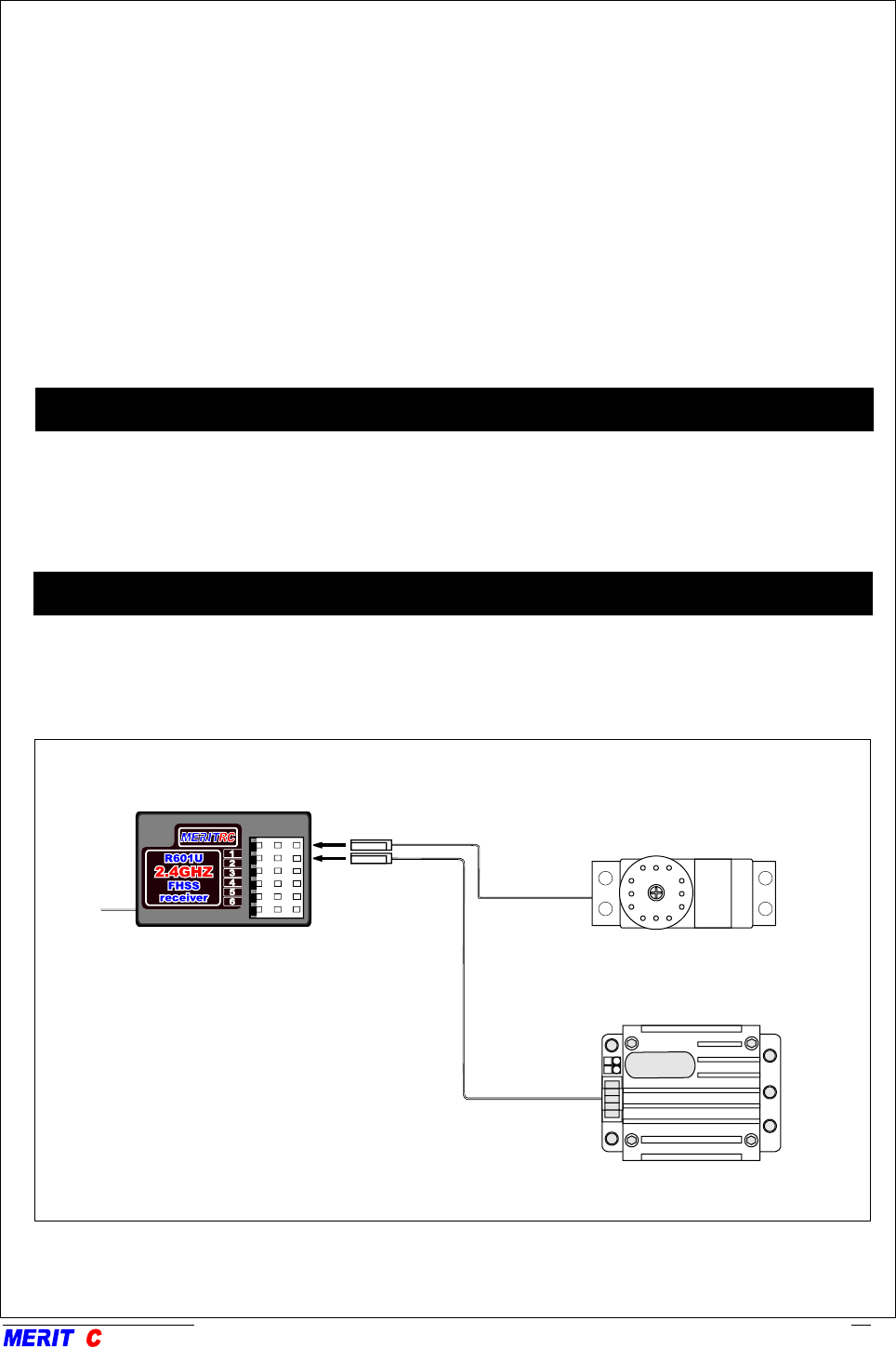
Connections
Connection example is shown below.
Connection Example
LED
* The number of servos depends
on the set.
Receiver
RR
6
Receiver
ESC
1. There is “Power Down Mode” build in for doing a ground range check to activate the “Power Down
Mode” by pressing the “PDM” button transmitter. The Green LED will turn off to indicate the PDM is
working. During this mode, the RF power is reduced so the range test can be performed.
2. Walk away from the car while simultaneously operating the controls. Have an assistant stand by the
model and signal what the controls are doing to confirm that they operate correctly. You should be
able to walk 30-50 paces approximately from the model without losing control.
3. If everything operates correctly, return to the car. The “Power Down Mode” continues for 60 seconds
and after that the power will go back to the normal level. To exit the “Power Down Mode” before the
60 seconds, press the “PDM” key again.
4. Never start flying when the “Power Down Mode” is active.
.
.
.
.
.
.
WARNING
Connector Connection
Insert the receiver, servo, and battery
connectors fully and firmly.
If vibration, etc. causes a connector to work
loose during running, the car may crash.
Servo Throw
Servo Installation
Install the servo to the servo mount,
etc. through a rubber grommet. Also
install the servo so that the servo
casedoes not directly touch the servo
mount or other parts of the chassis.
SCREW
GROMMET
BRASS EYELET
(Servo mount)
Receiver Vibration proofing
/ Waterproofing
<Antenna installation>
. .
Receiver Antenna
Do not cut or bundle the receiver
antenna. Also, do not bundle the
antenna together with the servo
lead wires. . .
Cutting or bundling the receiver antenna will
lower the receiver sensitivity and shorten
the flight range and cause a crash. ..
Operate the servo horn over its full
stroke and adjust so that the pushrod
does not bind or is not too loose. ..
Unreasonable force applied to the servo horn
will adversely affect the servo and drain the
battery quickly. ..
Vibrationproof the receiver by wrapping
it in sponge rubber or some such
material. If the receiver may get wet,
waterproof it by placing it in a plastic
bag.
If the receiver is subjected to strong vibra-
tion and shock, or gets wet, it may operate
erroneously and cause a crash.
Use a rubber grommet, etc. at the part at
which the antenna comes out of the body
through the antenna tube so that it will not
break. . .
RR
7
The operating direction, neutral position, and steering angel of servo are adjustable.
Adjustments
Adjustment Procedure
Before making any adjustments, set all the
SERVO REVERSER switches on the side of
the transmitter to the lower (NOR) position.
(Switch the switches with a small screwdriver,
etc.)
Turn on the transmitter and receiver power
switch and make the following adjustments:
1. Check the direction of
operation of the servo.
If a servo operates in the wrong direction,switch
its SERVO REVERSER switch.(The direction
of operation can be changed without changing
the linkage.)
2. Check the engine throttle
(speed adjustment) linkage.
Change the servo horn installation position
and hole position so that the throttle is opened
fully when the throttle stigger is set to HIGH
(back ward) and is closed fully when release
the throttle stigger
.
.
.
.
3. After all the linkages have
been connected, recheck the
operating direction, throw,
etc.
Before running adjust the car in accordance
with the kit and engine instruction manuals.
4. Run the car and trim the
servo.
RR
8