MERIT TECHNOLOGY TXT7HFMR 4CH 2.4GHz FHSS RADIO SYSTEM User Manual
SHANGHAI MERIT TECHNOLOGY CORP. 4CH 2.4GHz FHSS RADIO SYSTEM Users Manual
Users Manual
1213
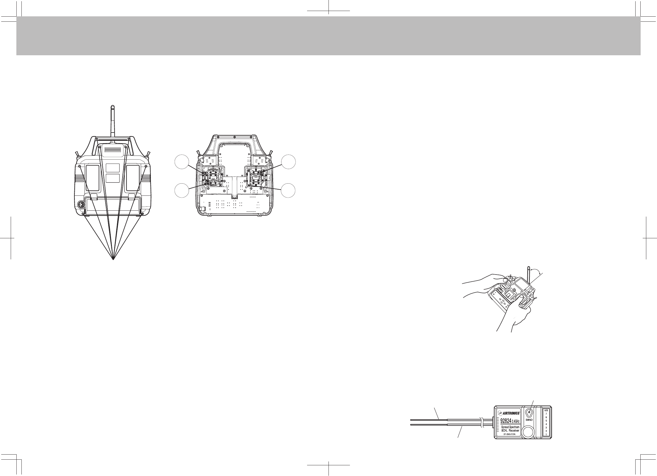
Antenna coaxial cable
Bind key & Bind LED
1
2
Screw Locations
3
4
Precautions on using the 2.4 GHz band
The 2.4 GHz band may be used by other devices, or other devices in the immediate area may cause
interference on the same band. Always before takeoff, conduct a bench test to make sure the servos operate
properly. Also, conduct checks with the transmitter as distant as possible from the aircraft. Safety is best
ensured by having an assistant carry the aircraft as far away as possible for checks.
Do not fly aircraft in the vicinity of areas in which wireless LANs are being used. Also, do not operate the
transmitter anywhere near cell phones or other devices that generate radio waves, etc. This can have
adverse effects such as shortening the coverage distance of the aircraft.
The response speed of the receiver can be affected if used where multiple 2.4 GHz radio controllers are
being used, therefore carefully check the area before takeoff. Also, if response seems slow while flying,
land immediately and stop flying.
Observe any applicable laws and regulations on fly zones when using the 2.4 GHz radio controller.
Unlike frequency bands used with earlier radio controllers, reception with this 2.4 GHz radio controller is
adversely affected by large obstructions and concrete or steel structures between the aircraft and
transmitter. Also, wire mesh and similar barriers can adversely affect operation. Keep this in mind in order
to fly the aircraft safely.
General precautions for use
Turn the transmitter ON first and then the receiver to fly the aircraft. When finished flying, turn the receiver
OFF first and then the transmitter. It is very dangerous to activate the components in reverse order as the
servo may start up inadvertently.
Before flying the aircraft, check that the batteries to the transmitter and receiver are sufficiently charged.
Precautions for use: Transmitter
TRANSMITTER STICK TENSION ADJUSTMENT
Toadjust the spring tension of the transmitter sticks you need to remove the back of the transmitter case. First
remove the antenna and the NiCd battery pack from the transmitter. Now remove the eight screws that hold the
case back in place, four in the main case, two in the LCD back cover and two on the handle.
Once the screws are removed swing the back of the case away from the transmitter being careful of the trainer
plug wiring.
There are four locations for the stick tension adjustment screws installed because the stick controlling the
throttle is ratcheted and has no tension adjustment. The #1 and #3 screws adjust the tension for the vertical
motion of each stick. The #2 and #4 screws adjust the tension for the horizontal motion of each stick. To make
the tension adjustment use a small phillips type screwdriver to turn the adjustment screws. Turning the screw
clockwise will increase the stick tension, turning it counterclockwise will decrease the tension. Once you have
completed your stick adjustments, replace the case back and install the NiCd battery pack and antenna. Be
careful to line the battery charging port pins when replacing the back cover.
Never touch the transmitter antenna while flying the aircraft. Doing so may cause loss of transmitter output,
making it impossible to operate the aircraft.
Keep the antenna of the transmitter perpendicular to the ground as best possible.
1.
Precautions for use: Receiver handling and mounting on aircraft
The receiver has 2 antenna wires. The thin section at the tip is the antenna reception wire, therefore mount the
antenna to the aircraft without bending the reception wire. Reception performance decreases if the reception
wire is bent.
1.
The transmitter's antenna is delicate. Handle with care.
Do not press the BIND key while flying the aircraft. The radio signal is interrupted while the BIND and trainer
keys are pressed. It may also require time to restore the signal after releasing the keys, which can be
dangerous.
2.
3.
1.
2.
3.
4.
5.
1.
2.
WARNING:
Any other modifications made to the transmitter other than adjusting stick tension will void any and all
warranties covered by Airtronics Inc.
Keep perpendicular to
ground.
Antenna reception wire
Federal Communication Commission Interference
Statement
This equipment has been tested and found to comply with the limits for a Class B
digital device, pursuant to Part 15 of the FCC Rules. These limits are designed
to provide reasonable protection against harmful interference in a residential
installation. This equipment generates, uses and can radiate radio frequency
energy and, if not installed and used in accordance with the instructions, may
cause harmful interference to radio communications. However, there is no
guarantee that interference will not occur in a particular installation. If this
equipment does cause harmful interference to radio or television reception, which
can be determined by turning the equipment off and on, the user is encouraged to
try to correct the interference by one of the following measures:
Reorient or relocate the receiving antenna.
Increase the separation between the equipment and receiver.
Connect the equipment into an outlet on a circuit different from that to which
the receiver is connected.
Consult the dealer or an experienced radio/TV technician for help.
FCC Caution: Any changes or modifications not expressly approved by the party
responsible for compliance could void the user's authority to operate this
equipment.
This device complies with Part 15 of the FCC Rules. Operation is subject to the
following two conditions: (1) This device may not cause harmful interference, and
(2) this device must accept any interference received, including interference that
may cause undesired operation.
This device and its antenna(s) must not be co-located or operating in conjunction
with any other antenna or transmitter.
IMPORTANT NOTE:
FCC Radiation Exposure Statement:
This equipment complies with FCC radiation exposure limits set forth for an
uncontrolled environment. This equipment should be installed and operated with
minimum distance 20cm between the radiator & your body.
EN50371:2002