MICROCHIP TECHNOLOGY RN4020 2.4GHz BLE MODULE User Manual
Microchip Technology Inc. 2.4GHz BLE MODULE
Contents
- 1. User Manual
- 2. User Mnaual Technical Spec.
User Manual

Microchip RN4020 Certified Bluetooth® Low
Energy OEM Module User Guide
1. Introduction
Microchip RN4020 Certified Bluetooth Low Energy (BTLE) OEM module is a single
mode Bluetooth Smart module that complies with Bluetooth Core Specification 4.0.
Through its high speed UART interface, it could be configured to act as either central
or peripheral role when establishing connection. It supports 13 public profiles and
18 public services, which are adopted by Bluetooth Special Interest Group (SIG). For
all supported profiles and services, RN4020 could be configured to act as server and
client roles at the same time. Furthermore, RN4020 supports Microchip private
profile Microchip Low Power Data Profile (MLDP) that simulates Serial Port Profile
(SPP), which is defined in Bluetooth Classic and enables data stream between two
devices. Finally, Microchip RN4020 also supports user self-defined private
profile/service, which could precisely fit user’s particular application. All
configurations will be saved in onboard no-volatile memory (NVM), so user only
needs set up the module once.
Microchip RN4020 provides user an easy-to-use, fast-to-market, very flexible and
powerful solution for BTLE technology.
2. Fundamental of Bluetooth Low Energy
When two BTLE devices want to be connected, one should be in central role and the
other in peripheral role. Peripheral would advertise to show its connectable status,
while central device will start the connection process. Once connected, either end of
connection could choose to bond. Once bonded, all security related key will be saved
and security process will be waived when reconnecting. Bonded peripheral device
could only perform direct advertise, therefore, no longer to able to connect to device
other than its bonded peer.
Similar to Bluetooth Classic, BTLE uses the concept of profiles to ensure
interoperability between different devices. Unlike Bluetooth Classic, BTLE profiles
are collection of services. All BTLE services are built on top of Generic Attribute
Profile (GATT), where GATT defines accessibility of attributes called characteristics.
The main functionality of BTLE profiles, therefore, is built around the
characteristics. For those devices that maintain the value of characteristics in a
service, such device is the server of the service. On the other hand, those devices
that acquire data from their peer are called client.
Each service and its characteristics could be identified by their Universally Unique
Identifier (UUID). The UUID could be either short form (16bit) or long form
(128bit). All Bluetooth SIG adopted services and characteristics have short UUID,

while user self-defined private UUID must be in long form. For the details of
Bluetooth SIG adopted services and characteristics, please refer to
https://developer.bluetooth.org/gatt/profiles/Pages/ProfilesHome.aspx.
The accessibility of each characteristic is defined by 8-bit characteristic property in
bitmap format, as shown in table 1.
Table 1. Characteristic Properties
Property
Bitmap
Description
Extended
Property *
0b10000000
Additional property available
Authenticated
Write *
0b01000000
Write characteristic with authentication from client
to server
Indicate
0b00100000
Indicate value of characteristic with
acknowledgement from server to client
Notify
0b00010000
Notify value of characteristic without
acknowledgement from server to client
Write
0b00001000
Write value of characteristic with acknowledgement
from client to server
Write without
response
0b00000100
Write value of characteristic without
acknowledgment from client to server
Read
0b00000010
Read value of characteristic. Value is sent from
server to client
Broadcast
0b00000001
Broadcast value of characteristic
* Currently not supported in RN4020
3. Microchip RN4020 OEM Module Control Interface
Microchip RN4020 module is fully agent certified Bluetooth Low Energy single
mode OEM module. User controls the module through GPIO lines and UART
interface.
3.1 RN4020 GPIO Control Lines
RN4020 uses 3 input GPIOs to set the module in different states and 3 output GPIOs
to indicate current status.
GPIO 3 is used to control the operating state of RN4020. When GPIO 3 is put to high,
the module wakes up and is set into active mode. Once waking up, “CMD” will be
output to the UART and indicate that module is in command mode and ready to take
commands from UART.
On the other hand, when GPIO 3 is set to be low, the module will exit command
mode by output “END” to UART and then operates in deep sleep mode. UART

interface will not be responsive in deep sleep mode. When the module is in deep
sleep mode, GPIO 9 will output low.
GPIO 4 is used to control RN4020 when Microchip private MLDP profile is used.
Once get into MLDP mode by setting GPIO 4 at high, all data from UART will be sent
to the peer device as data stream. To exit MLDP mode, user needs to put GPIO 4 low,
so that module is back to command mode by outputting “CMD” to UART.
Setting pin BT_WAKE high is used to wake RN4020 module from dormant mode.
When RN4020 module is connected to a peer device, GPIO 5 will output high;
otherwise, GPIO 5 outputs low.
When in MLDP mode, if RN4020 needs outputting status and/or requesting
response from the host MCU, GPIO 6 will be put to high. Once RN4020 exit MLDP
mode and getting back to CMD mode, status and/or requests will be output to UART.
Once stored data is output to UART, GPIO 6 will be put to low. The maximum buffer
of status/requests is 256 bytes.
When RN4020 module is in active mode, GPIO 7 will output high; otherwise, GPIO 7
outputs low.
3.2 RN4020 UART Control Interface
UART is the main control interface for RN4020. The default UART port configuration
for RN4020 is shown in table 2.
Table 2: RN4020 UART Configuration
Parameter
Value
Baud Rate
115200
Data Bits
8
Parity
None
Stop Bits
1
Flow Control
None (CTX/RTX in the
future)
The UART baud rate could be adjusted from 2400 to 932K with command “SB”.
Notice that when UART baud rate is set to 2400, there is no need to wake up the
module from GPIO 3 before communicating with the module.
All control are through AT-Commands and their parameters. All commands and
parameters are separated by comma. No space allowed between command and
parameters. All commands are finished by line feed or return.

All commands could be divided into five groups: Set/Get commands, Action
commands, characteristic access commands, private service configuration
commands and Microchip MLDP commands.
3.2.1 Set/Get commands
This group of commands is used to configure the functionality of RN4020 module.
The set command starts with letter ‘S’ and follow by one or two letters as the
command identifier. The set command parameter is mandatory and it is separated
from the command by comma. The format of set command could be seen in Figure 1.
Figure 1: Set Command Format
S
Command Identifier
,
Input Parameter
It is highly desirable to perform a reboot after the set command so the new settings
could be effective afterwards. All configurations from Set command will be stored in
the NVM of RN4020 module and restored after powering cycle or reset. All set
command has corresponding get command to output the configurations to the
UART. Get command has the same command identifier as set command but no
parameters.
3.2.1.1 S-,<string>
This command sets the serialized friendly name of the device, where <string> is up
to 15 alphanumeric characters. This command automatically appends the last 2
bytes of the Bluetooth MAC address to the name, which is useful for generating a
custom name with unique numbering.
Default: N/A
Example: S-,MyDevice // Set device name to “MyDevice-ABCD”
3.2.1.2 S@,<0-2>,<hex16>
This command set the analogue port output voltage. There are two parameters for
this command. The first parameter could be 0, 1 or 2, specifying the analogue port
number. The second parameter is the output voltage in mV. Notice the range of
output voltage is between 0 – 1.3V. When outputting analogue signal, RN4020 could
not be run under deep sleep mode. Instead, the firmware will automatically adjust
the operation mode to shallow sleep. Once analogue output is turned off by issuing
command “S@,<0-2>,0000”, the firmware will again automatically adjust the
operation mode back to deep sleep when available.
Example: S@,1,03E8 // Set AIO1 output voltage to be 1000mV

3.2.1.3 SB,<0-7>
This command set the baud rate of the UART communication. The input parameter
is single digit number in the range of 0 to 7, representing baud rate from 2400 to
921K, as shown in table 3. Notice that when baud rate is set to 2400, there is no
need to wake up RN4020 for UART communication.
Table 3: UART Baud Rate Settings
Setting
Baud Rate
Comments
0
2400
RN4020 does not need to be
waken up.
1
9600
2
19200
3
38400
4
115200
5
230400
6
460800
7
921600
3.2.1.4 SC,<hex32>
This command sets the supported client services. The input parameter is 32bit
bitmap, which indicates the services this device supports as client role. When
corresponding bit is set, the service is supported as client role in this device.
Supporting a service as client role means all characteristics of such service on the
peer device could be accessed, if the peer device as server role supports such
service. The bit map of supported services could be seen in table 4.
Table 4: Bitmap of Services
Service
Bitmap
Used in Profiles
Device Information
0x80000000
Blood Pressure, Cycling Speed Cadence,
Glucose, Health Thermometer, Heart Rate,
Running Speed Cadence
Battery
0x40000000
Heart Rate
0x20000000
Heart Rate
Health Thermometer
0x10000000
Health Thermometer
Glucose
0x08000000
Glucose
Blood Pressure
0x04000000
Blood Pressure
Running Speed
Cadence
0x02000000
Running Speed Cadence
Cycling Speed
0x01000000
Cycling Speed Cadence

Cadence
Current Time
0x00800000
Time
Next DST Change
0x00400000
Time
Reference Time
Update
0x00200000
Time
Link Loss
0x00100000
Proximity
Immediate Alert
0x00080000
Find Me, Proximity
TX Power
0x00040000
Proximity
Alert Notification
0x00020000
Alert Notification
Phone Alert Status
0x00010000
Phone Alert Status
Scan Parameters
0x00004000
Scan Parameters
Location & Navigation
0x00001000
Location & Navigation
User Defined Private
Service
0x00000001
User Defined Private Profile
Default: 00000000
Example: SC,C00000 // Support Device info and Battery
// services as client role
3.2.1.5 SDF,<text>
This command set the value of firmware revision characteristic in Device
Information Service.
Device Information Service is used to identify the device. All its characteristics
rarely change. Therefore, values of characteristics in Device Information Service
could be set and saved into NVM. All values of characteristic in Device Information
Service have maximum size of 20 bytes.
Default: 0.9
Example: SDF,0.9
3.2.1.6 SDH,<text>
This command set the value of hardware revision characteristics in Device
Information Service.
Default: 2.1
Example: SDH,2.1
3.2.1.7 SDM,<text>
This command set the value of model characteristics in Device Information Service.

Default: RN4020
Example: SDM,RN4020
3.2.1.8 SDN,<text>
This command set the value of manufactory name characteristics in Device
Information Service.
Default: Microchip
Example: SDN,Microchip
3.2.1.9 SDP,<text>
This command set the value of PnP ID characteristics in Device Information Service.
Default: N/A
Example: SDP,N/A
3.2.1.10 SDR,<text>
This command set the value of software revision characteristics in Device
Information Service.
Default: 1.0
Example: SDR,1.0
3.2.1.11 SDS,<text>
This command set the value of serial number characteristics in Device Information
Service.
Default: N/A
Example: SDS,12345678
3.2.1.12 SF,<1,2>
This command reset the configurations into factory default. The parameter of this
command could be 1 or 2.

When input parameter is 1, majority of the settings will be restored to factory
default, but some settings, such as device name, device info, script and private
services, stay the same. When input parameter is 2, all parameters are restored to
factory default.
Example: SF,1
3.2.1.13 SM,<1,2>,<hex32>
This command starts one of the application timers. The first parameter is the
identifier of the timer to start and the second parameter is the timer expiration time
in macro-Second if the value is in the range between 0x00000001 and 0x7FFFFFFF.
Second parameter outside the above range will stop the timer.
Example: SM,1,00100000 // start the timer 1 to expire in about 1
// second
SM,1,FFFFFFFF // stop timer 1 immediately
3.2.1.14 SN,<text>
This command sets the device name, where <string> is up to 20 alphanumeric
characters.
Example: SN,MyDevice // Set the device name to “MyDevice”
3.2.1.15 SR,<hex16>
This command set the supported feature of current RN4020 device. The input
parameter is 16-bit bitmap that indicates features to the supported. After changing
the features, a reboot is necessary to make the changes effective. The bitmap of
features could be seen in table 5.
Table 4: Bitmap of Features
Feature
Bitmap
Description
Central
0x8000
If set, device is central that starts the
connection. If cleared, device is
peripheral that starts advertisement.
Buffered Read
0x4000
If set, device read from RN4020 internal
RAM for characteristic values that are
set beforehand. If cleared, device request
values from host MCU through UART
and host MCU must respond in timely
manner.

Auto Advertise
0x2000
This setting applies to peripheral device
only. If set, device starts advertisement
after power cycle, reboot or
disconnection. If cleared, device starts
advertisement after receiving command
“A” from UART in command mode.
Support MLDP
0x1000
If set, the device supports Microchip
private service MLDP that simulates
Serial Port Profile with data stream. If
cleared, MLDP is disabled.
Auto MLDP
Disable
0x0800
This setting is only effective when MLDP
is enabled. If set, the device enters MLDP
mode after receiving command “I” from
UART in command mode or set GPIO 4
to high. If cleared, the device enters
MLDP mode not only by command “I” or
GPIO4 pin, but also by receiving MLDP
data stream from peer device.
No Direct
Advertisement
0x0400
This setting is only effective for
peripheral devices. If set, peripheral will
not issue direct advertisement even if it
is bonded, therefore it is discoverable
whenever it is advertising. This setting is
useful when working with iOS or
Android devices.
UART Flow
Control
0x0200
This setting is used to control RTS/CTS
hardware flow control on RN4020 UART
port. If set, flow control is enabled and
host needs to support UART hardware
flow control feature.
Run Script After
Power On
0x0100
This setting is used to control script
execution. If set, after powering on,
script running will be automatically
started by generating @PW_ON event.
Enable Battery
Monitor
0x0080
This setting enables battery monitor.
Battery voltage will be checked once per
10 minutes. Once battery voltage is
below threshold set by command “SV”,
notifications are triggered. Message
“Battery Low” will be output to UART
and low priority alert @ALERTL will be
generated if scripting capability is
enabled.
Enable
Authentication
0x0040
This setting enables authentication
during connection, preventing Man-In-

The-Middle (MITM) attack. When
authentication is enabled, IO capability
is set to be keyboard and display. Refer
to table 2.5 in Bluetooth Core Spec v4.1
Vol 3, Part H, section 2.3.5.1 for details.
Enable Remote
Command
0x0020
This setting is only effective if MDLP
feature is enabled. This setting enables
local device to receive remote command
from remote device and send command
output to remote device through MLDP
data stream.
Do not Save
Bonding
0x0010
Once set, the bonding information won’t
be saved in NVM and the bonding is only
valid for current connection.
IO Capabilities
0x000E
IO capability of the module. Only useful
if Enable Authentication bit is set.
000b: Display Only
001b: Display Yes/No
010b: Keyboard Only
011b: No Input, no output
100b: Keyboard Display
Default: 0000
Example: SR,6000 // Set device as peripheral, buffered read
// and automatically start advertisement
3.2.1.16 SS,<hex32>
This command sets the services to be supported by the device as server role. The
input parameter is 32-bit bitmap that indicates the services to be supported as
server. Supporting service as server role means that host MCU needs to supply the
values of all characteristics in supported services and provides client access to those
values upon requesting. Once the service bitmap is modified, the device must reboot
to make the new services effective. The 32-bit bitmap could be found in table 5.
Table 5: Bitmap of Services
Service
Bitmap
Used in Profiles
Device Information
0x80000000
Blood Pressure, Cycling Speed Cadence,
Glucose, Health Thermometer, Heart Rate,
Running Speed Cadence
Battery
0x40000000
Heart Rate
0x20000000
Heart Rate
Health Thermometer
0x10000000
Health Thermometer
Glucose
0x08000000
Glucose

Blood Pressure
0x04000000
Blood Pressure
Running Speed
Cadence
0x02000000
Running Speed Cadence
Cycling Speed
Cadence
0x01000000
Cycling Speed Cadence
Current Time
0x00800000
Time
Next DST Change
0x00400000
Time
Reference Time
Update
0x00200000
Time
Link Loss
0x00100000
Proximity
Immediate Alert
0x00080000
Find Me, Proximity
TX Power
0x00040000
Proximity
Alert Notification
0x00020000
Alert Notification
Phone Alert Status
0x00010000
Phone Alert Status
Scan Parameters
0x00004000
Scan Parameters
Location & Navigation
0x00001000
Location & Navigation
User Defined Private
Service
0x00000001
User Defined Private Profile
Default: 00000000
Example: SS,060000 // support blood pressure and
// running speed cadence as
// server role
3.2.1.17 ST,<interval>,<latency>,<timeout>
This command sets the initial connection parameters for future connections. The
three input parameters are all 16-bit value in hex format. To modify current
connection parameters, please refer to action command “T”.
For central device, the connection parameters will be used to establish connections
with peripherals. For peripheral device, the connection parameters will be used to
request the connection update once a new connection is established. Acceptance of
connection update from a peripheral device depends on central device.
The corresponding get command “GT” returns the desirable connection parameters
set by command “ST” when connection is not established. Once connection is
established, the actual connection parameters will be displayed in response to
command “GT”.
Connection interval, latency and timeout are often associated with how frequent
that a peripheral device needs to communicate with central, therefore, closely
related to power consumption. The three parameters’ range and relationship are
listed in table 6

Table 6 Connection Parameters
Parameter
Range
Description
Interval
0x0006 – 0x0C80
The time interval of communication
between two connected devices. (unit:
1.25ms)
Latency
0x0000 – 0x01F3
must less than
(Timeout*10/Interval*1.25-
1)
The number of consecutive connection
events that the peripheral does not
need to communicate with central.
Timeout
0x000A – 0x0C80
The maximum time between raw
communications before the link is
considered lost. ((unit: 10ms)
Default: 0006,0000,0064
Example: ST,0064,0002,0064 // Set the interval to be 125ms,
// latency to be 2 and timeout to
// 1 second
3.2.1.18 SV,<hex16>
This command set the battery monitor threshold. This command took effect if
battery monitor feature is enabled by command “SR”. The parameter is the battery
voltage in mV. Battery voltage is checked once per 10 minutes. Once the battery
voltage is lower than the threshold, message “Battery Low” is output to UART and
the event of low priority alert is generated.
Default: 09C4 // default battery voltage threshold 2500mV
Example: SV,0A28 // Set battery voltage threshold 2600mV
3.3.2 Action Commands
The group of action commands is mainly used to initiate functionality as well as
display critical information.
3.3.2.1 +
Command “+” toggles the local echo on and off. If send the “+” command in
command mode, all typed characters are echoed to the output. Typing + again will
turn local echo off. Command “+” does not have parameter.
Default: Off
Example: + // Turn local echo on

3.3.2.2 A,<hex16>,<hex16>
Command “A” is only available to device that operates as peripheral or broadcacster
role. Command “A” is used to start advertisement.
When the device acts as broadcaster role, enabled by command “N”, the
advertisement is undirected, un-connectable manufacture specific broadcast
message. The payload of the message is set by command “N”.
When the device acts as peripheral role, and it is not bonded, the advertisement is
undirected connectable, which means all BTLE central device could find it. When the
device is bonded, the advertisement is directed if no_direct_adv bit is cleared with
command SR; otherwise the advertisement is undirected if no_direct_adv bit is set.
When direct advertisement is used, it is directed to the bonded device so that other
BTLE devices could not be heard.
When command “A” is issued without parameter, the advertisement interval is
default to be 100ms and advertise indefinitely. Command “A” could be followed by
two 16bit hex parameters, which indicates advertisement interval in millisecond
and total advertisement time in millisecond. The second parameter must be larger
than the first parameter.
Default: 100 (millisecond)
Example: A,0050,07D0 // Start advertisement with
// interval of 80 millisecond for 2 seconds
3.3.2.3 B,<0,1>
Command “B” is used to secure the connection and bond two connected devices.
Command “B” is only effective if two devices are already connected. Bonding could
be issued from either central or peripheral device.
If no input parameter is provided or the input parameter is 1, the connection will be
secured and the peer device remembered. In this situation, we call the two devices
are bonded. If the input parameter is 0, the connection is secured but peer device is
not saved into NVM. In this situation, the connection is not bonded.
Once bonded, security materials will be saved in both end of connection if
“do_not_save_bonding” setting is cleared by command “SR”. Therefore reconnection
between bonded devices does not require authentication, so reconnection could be
done in a very short time. For bonded peripheral devices, the advertisement could
only be directed. As the result, bonded peripheral devices are not available for
inquiry or connection.

After bonded connection is lost due to any reason, reconnection does to provide
secured link automatically. To secure the connection, another “B” command should
be issued. However, this command is only for securing link other than saving
connection information.
Default: Not bonded
Example: B // bond with connected peer device
3.3.2.4 D
Command “D” is used to display critical information of current device over UART.
Following information will be shown after issuing command “D”.
Device MAC Address
Device Name
Device Connection Role – Central or Peripheral
Connected Device: Show MAC address and address type (Public or Random) if
connected, or “no” if no active connection.
Bonded Device: Show MAC address and address type (Public or Random) if
connected, or “no” if no bonding device
Server Services: Bitmap of services that are supported as server role
Command “D” has no parameter
Example: D // Dump information
3.3.2.5 E,<0,1>,<mac address>
Command “E” is only available to device as central role. It starts the process to
establish connection with a peer peripheral device.
If the central device is already bonded with a peripheral, issuing command “E” will
automatically start the process of connecting with the bonded peripheral. Usually,
bonded central device needs to issue command “E” first and then bonded peripheral
start directed advertisement.
If the central device is not bonded with the peripheral, two input parameters are
required to establish connection with a peripheral device. The first parameter is
MAC address type and second parameter is MAC address of the peripheral device.
MAC address type is either 0 for public address or 1 for random address. The
address type should be available in the result of inquiry with command “F”. The
second parameter is 6 byte MAC address, which is also available from result of
command “F”.

Default: Bonded MAC Address
Example: E,0,00035B0358E6 // Connect to peripheral with
// public address 00035B0358E6
3.3.2.6 F,<hex16>,<hex16>
Command “F” is only available to device as central or observer role. For central
device, it is used to inquiry the peripheral devices before establishing connection.
For observer, it is used to receive broadcast messages.
If no parameter is provided, command “F” starts the process of connection with
default scan interval of 375 milliseconds and scan window of 250 milliseconds. User
has the option to specify the scan interval and scan window as first and second
parameter respectively as 16bit hex value in millisecond.
Default: 375ms for scan interval, 250ms for scan window
Example: F,012C,00C8 // Start Inquiry with 300ms scan interval
// and 200ms scan window
3.3.2.7 H
Command “H” sends help page to UART. The help page is grouped into “Set
Commands”, “Action Commands”, “Service Commands”, “Private Service Commands”
and “MLDP Commands”. According to the feature settings from “Set Commands”, the
help page displays only commands that are applies to current settings.
Command “H” has no parameter.
Example: H // Display the help page
3.3.2.8 J,<0,1>
Command J put the device into or out of observer role.
If the input parameter is 1, RN4020 enters observer mode. After issuing command
“F”, RN4020 could receive undirected, un-connectable advertisement from
broadcasters.
If the input parameter is 0, RN4020 exits observer mode.
Example: J,1 // Enter observer mode. To receive broadcast,
// command “F” must be issued.

3.3.2.8 K
Command “K” is used to disconnect the active BTLE link. It could be used as a
central or peripheral role. Command “K” does not have any parameter.
Example: K // Kill the active BTLE connection
3.3.2.9 M
Command “M” is used to get the signal strength of last communication with peer
device. The signal strength could be used to estimate the distance between the
device and its peer. Command “M” does not expect any parameter.
The return value of command “M” is the signal strength in dBm. The accuracy of the
result is within 6dBm.
Example: M // check the signal strength of last
// communication with peer device
3.3.2.10 O
Command “O” puts the module into dormant mode that consumes very little power.
It has no parameter and could be issued by either central or peripheral device.
When RN4020 is in dormant mode, the power consumption is less than 600nA. As
comparison, power consumption is less than 5uA in deep sleep mode. Once enter
dormant mode, GPIO 9 will assert low, all connection will be lost as well as any data
in RAM. To exit from dormant mode, pull the WAKE pin high. Once exit from
dormant mode, RN4020 behaves the same as after reboot.
Example: O // Enter low power dormant mode
3.3.2.11 Q
Command “Q” shows current connection status. It has no parameter and can be
issued by either central or peripheral device.
When device is disconnected, RN4020 module will return status as “No Connection”.
Otherwise, the return status includes peer device’s MAC address, address type
(public or random) and the primary service record UUIDs that current device
support as client role. Command “SC” sets the services that current device could
support as client role. Whether to support those services depends on whether the

connected device supports those services as server role. Command “Q” lists the
UUIDs of services that current device support as client role and connected peer
support as server role.
Default: No Connection
Example: Q // Display the connection status
3.3.2.12 R,1
Command “R” forces a complete device reboot (similar to a power cycle). It has one
mandatory parameter of “1”. After rebooting RN4020, all prior setting change takes
effective.
Example: R,1 // Reboot RN4020
3.3.2.13 T,<interval>,<latency>,<timeout>
Command “T” is used to change connection parameters interval, latency and timeout
for current connection. The parameters of command “T” is lost after power cycle. All
parameters are 16-bit value in hex format. Command “T” is only effective if active
connection exists when the command is issued.
For the definitions, ranges and relationships of connection interval, latency and
timeout, please refer section 3.2.1.15 for command “ST” and table 6 for details.
When command “T” with valid parameters is issued by peripheral device, minimum
interval of Timeout is required between two connection parameter update requests.
Also, whether to accept the connection parameter update request is up to the
central device. When RN4020 acts as central device, it accepts all valid connection
parameter update requests.
Default: Interval: 20; Latency: 0; Timeout: 200
Example: T,0190,0001,03E8 // Request Connection Parameter
// to be interval 400ms, latency 1
// and timeout 1000ms
3.3.2.14 U
Command “U” removes existing bonding. It expects no parameter and could be
issued by either central or peripheral.

Command “U” not only removes the bonding, but also changes advertisement
method. If a peripheral is advertising when command “U” is issued, RN4020 will
remove the bonding, stop the directed advertisement, and then start undirected
advertisement.
Example: U // remove existing bond
3.3.2.15 V
Command “V” displays the firmware version.
Example: V // display firmware version
3.3.2.16 X
Command “X” is only available to central or observer device. For central device, it
stops inquiry process. For observers, it stops to receive broadcast messages.
Command “X” expects no parameter.
Example: X // stop inquiry
3.3.2.17 Y
Command “Y” is only available to peripheral or broadcaster device. It stops
advertisement that starts by command “A”. Command “Y” expects no parameter.
Example: Y // stop advertisement.
3.3.2.18 Z
Command “Z” is only available to central device. It stops connection process that
starts with command “E”. Command “Z” expects no parameter.
Example: Z // stop connection process
3.3.3 Characteristic Access Commands
The main functionality of BTLE profiles and services are providing access to the
values and configurations of characteristics. RN4020 provides a group of commands
to address this issue.

3.3.3.1 Definition of Characteristic Access Commands
RN4020 could be configured to act as server and client at the same time. When it
performs dual roles as server and client, two sets of services and characteristics are
known to RN4020. For services that RN4020 acts as server, it is called server
services, where all values and configurations of characteristics are stored locally.
For services that RN4020 acts as client, it is called client services, where all data and
configurations of characteristics are stored remotely in peer device. To address
server services, the first letter of characteristic access commands is “S”; to address
client services, the first letter of characteristic access commands is “C”.
Bluetooth SIG adopted a group of public services specifications, which are the basis
of interoperability between devices. All service and characteristics in the service
have been assigned 16-bit short UUIDs. On the other hand, users are able to define
their own private service and its associated characteristics with 128-bit long UUIDs.
On the other hand, even it is rare; one public characteristic may be used in more
than one service. Furthermore, because addressing 128bit private characteristic
may not be so efficient, RN4020 provides a unique 16bit reference of handle to each
characteristic. Therefore, a characteristic could be addressed either by its UUID or
its handle. To address a characteristic by its UUID, the second letter of characteristic
access commands is “U”; to address a characteristic by its handle, the second letter
of characteristic access commands is “H”.
In addition, the value or configuration of a characteristic could either be read or
write. To read a characteristic, the third letter of characteristic access commands is
“R”; to write a characteristic, the third letter of characteristic access commands is
“W”.
Finally, access to a characteristic may be directed to its value, or its configuration.
Usually, only the client services needs to access the configuration of a characteristic.
If address by handle, this problem has been solved, since value and configuration of
a characteristic have different handles. But if addressing by UUID, a fourth letter “V”
or “C” needs to be added to indicate whether the access request to client service is
for value or configuration of a characteristic.
Before addressing the characteristics, user may want to know accessible
characteristics. Characteristic Access commands group provides two commands, LC
and LS, to list the client services and server services respectively.
3.3.3.2 LC
Command “LC” lists the available client services and their characteristics. Client
services and their characteristics are only available under two conditions:
An active connection exists

Peer device supports services as server role.
The output of command “LC” follows format below:
The first line is primary service uuid
The second line starts with two spaces and then follows the characteristic uuid,
handle and characteristic property.
The property for characteristic value follows definition in table 1. Property for
characteristic value must have bit 4 and bit 5 cleared (no notification or
indication), while property for characteristic configuration must have either bit
4 or bit 5 set.
Figure 2 shows Battery service output. 0x180F is UUID for Battery Service. The
second line shows that Battery Level UUID 0x2A19, its handle 0x001A and property
0x02 (Readable, a value handle, see Table 1,). The third line shows Battery Level
UUID 0x2A19, its handle 0x001B and property 0x10 (Nodify, a configuration
handle).
Figure 2: Listing Client Service and Characteristics
180F
2A19,001A,02
2A19,001B,10
When command “LC” has no parameter, it displays all client services along with
their characteristics. Command “LC” could optionally take one or two parameters. If
one parameter is given to command “LC”, it must be UUID of client service. Then
only the client service with given UUID and all its characteristics are displayed. If
two parameters are given to command “LC”, the first parameter is the UUID of client
service and the second parameter is UUID of its characteristic. Then only the
characteristic with given UUID in the client service of given UUID are displayed.
Example: LC // Display all client services
3.3.3.3 LS
Command “LS” list the server services and their characteristics.
The output format of command “LS” is very similar to that of command “LC” as
follows:
The first line is primary service uuid
The second line starts with two spaces and then follows the characteristic uuid,
handle and letter “V” or “C” to indicate value handle or configuration handle
respectively.

When command “LS” has no parameter, it displays all server services along with
their characteristics. Command “LS” could optionally take one or two parameters. If
one parameter is given to command “LC”, it must be UUID of server service. Then
only the server service with input UUID along with all its characteristics will be
displayed. If two parameters are given to command “LS”, the first parameter is the
UUID of server service and the second parameter is UUID of its characteristic. Then
only the characteristic with given UUID in the server service with given UUID is
displayed.
Example: LS // Display all server services
3.3.3.4 CHR
According to command interpolation method described in section 3.3.3.1, command
“CHR” reads content of characteristic of client service from remote device by
addressing its handle.
The parameter of command “CHR” is 16-bit hex value of the handle, which
corresponds to a characteristic of client service. User should be able to find match
between handle and its characteristic UUID by command “LC”.
This command is only effective if an active link with peer exists, the handle
parameter is valid and the corresponding characteristic is readable according to its
property. The value returned is retrieved from remote peer device.
Example: CHR,001A // Read the content of characteristic with
// handle 0x001A from remote device
3.3.3.5 CHW
According to command interpolation method described in section 3.3.3.1, command
“CHW” writes content of characteristic in client service from remote device by
addressing its handle.
This command takes two parameters. The first parameter is 16-bit hex value of the
handle, which corresponds to a characteristic of client service. User should be able
to find match between handle and its characteristic UUID by command “LC”. The
second parameter is the content to be written to the characteristic. The format of
each public characteristic is defined in Bluetooth SIG specifications. User defines the
format of each private characteristic.
This command is only effective if an active link with peer exists, the handle
parameter is valid and the corresponding characteristic is writable according to its

property. The content value is written to remote peer device. The writing method
depends on property of the characteristic.
When writing to a configuration handle to the remote device, Bluetooth
specification defines the format to be 0x0000, 0x0001 or 0x0002. Value 0x0001 (01
00 over the air in little endian) starts notification, value 0x0002 (02 00 over the air
in little endian) starts indication and value 0x0000 stops both of them. To start
notification or indication depends on service specification as well as property of the
characteristic. Please refer to Table 1 and Figure 2 for details.
Example: CHW,001A,64 // Set value of characteristic
// with value handle 0x001A to be
// 100 on remote device
CHW,001B,0100 // Start notification on characteristic
// by writing 0x0001 to its configuration
// handle 0x001B on remote device
3.3.3.6 CURC
According to command interpolation method described in section 3.3.3.1, command
“CURC” reads configuration of a characteristic in client service from remote device
by addressing its UUID.
This command expects one parameter, which is the UUID of the characteristic in
client service. The UUID could be either 16-bit short UUID for public characteristic,
or 128bit long UUID for private characteristic. Only characteristic with property of
notification or indication has configuration, therefore, addressable by this
command.
This command is only effective if an active link with peer exists and the UUID
parameter is valid. The configuration of a characteristic, if exists, is always readable.
The value returned is retrieved from remote peer device.
The return value is 0000, 0100 or 0200, or endian format for value 0x0000, 0x0001
and 0x0002. Return value 0000 means no indication or notification starts; return
value 0100 means notification starts and 0200 means indication starts.
Example: CURC,2A19 // Read configuration of characteristic
// Battery Level with UUID 0x2A19 from
// remote device
3.3.3.7 CURV

According to command interpolation method described in section 3.3.3.1, command
“CURV” reads value of a characteristic in client service from remote device by
addressing its UUID.
This command expects one parameter, which is the UUID of the characteristic in
client service. The UUID could be either 16-bit short UUID for public characteristic,
or 128bit long UUID for private characteristic.
This command is only effective if an active link with peer exists, the UUID parameter
is valid and the characteristic is readable according to its property. The value
returned is retrieved from remote peer device.
Example: CURV,2A19 // Read value of characteristic
// Battery Level with UUID 0x2A19
// from remote device
3.3.3.8 CUWC
According to command interpolation method described in section 3.3.3.1, command
“CUWC” writes configuration of a characteristic in client service to remote device by
addressing its UUID.
This command expects two parameters. The first parameter is the UUID (either
16bit short UUID or 128bit long UUID) of the characteristic. The second parameter
is either “0” or “1”. Parameter “1” means starting notification or indication,
depending on the property of configuration handle. Parameter “0” turns off
notification or indication. Only characteristic with property of notification or
indication has configuration, therefore, addressable by this command.
This command is only effective if an active link with peer exists and the UUID
parameter is valid. The characteristic configuration, if exists, is always writable.
Example: CUWC,2A19,1 // Start notification on remote device
// for characteristic Battery Level with
// UUID 0x2A19
3.3.3.9 CUWV
According to command interpolation method described in section 3.3.3.1, command
“CUWV” writes value of a characteristic in client service to remote device by
addressing its UUID.
This command expects two parameters. The first parameter is the UUID (either
16bit short UUID or 128bit long UUID) of the characteristic. The second parameter

is hex value of the contents to be written. The format of public characteristic is
defined in Bluetooth SIG specifications. The user defines the format of private
characteristic.
This command is only effective if an active link with peer exists, the UUID parameter
is valid and the characteristic is writable according to its property. The content
value is written to remote peer device. The writing method depends on property of
the characteristic.
Example: CUWV,2A19,64 // Write 100% to remote device for
// characteristic Battery Level with
// UUID 0x2A19
3.3.3.10 SHR
According to command interpolation method described in section 3.3.3.1, command
“SHR” reads content of characteristic of server service on local device by addressing
its handle.
The parameter of command “SHR” is 16-bit hex value of the handle, which
corresponds to a characteristic of a server service. User should be able to find match
between handle and its characteristic UUID by command “LS”.
This command is effective with or without an active link. Reading contents of a
characteristic locally is always permitted regardless of characteristic property.
Characteristic property is only used for remote access. The value returned is
retrieved from local device and equal to what is written at most recent time.
Example: SHR,001A // Read the local content of characteristic with
// handle 0x001A
3.3.3.11 SHW
According to command interpolation method described in section 3.3.3.1, command
“SHW” writes content of characteristic in server service to local device by
addressing its handle.
This command takes two parameters. The first parameter is 16-bit hex value of the
handle, which corresponds to a characteristic of server service. User should be able
to find match between handle and its characteristic UUID by command “LS”. The
second parameter is the content to be written to the characteristic. The format of
each public characteristic is defined in Bluetooth SIG specifications. User defines the
format of each private characteristic.

This command is effective only if the handle is valid in server service. Characteristic
in server service is always writable regardless of its property. Characteristic
property is only for remote access. The content of a configuration handle, which
starts or stops notification/indication, is usually set remotely. We highly
recommend not writing to configuration handle, although such operation is not
prohibited.
When Buffered Read feature (See section 3.2.1.12 for command “SR”) is not enabled,
RN4020 requests content of a characteristic from the host MCU, when receiving
read request from the remote device. The host MCU needs to use command “SHW”
or “SUW” to write the content and therefore responds to the request.
When command “SHW” is issued to change the local content of characteristic, a
notification or indication might be send to remote device, if following conditions are
met:
An active connection exists
Remote device support the corresponding service and characteristic as client
role
Property of corresponding characteristic supports notification or indication
Notification or indication service for the corresponding characteristic has been
started by the remote device
Example: SHW,001A,64 // Set local value of characteristic Battery
// Level with value handle 0x001A to be
// 100%. If notification service has been
// started on Battery Level before, local
// device will notify the new value of
// 100% to the remote peer device
3.3.3.12 SUR
According to command interpolation method described in section 3.3.3.1, command
“SUR” reads value of characteristic in server service on local device by addressing its
UUID.
The parameter of command “SUR” is hex value of the UUID of a characteristic. The
UUID could be either 16-bit short UUID for public characteristic, or 128bit long
UUID for private characteristic.
This command can only read value of a characteristic. Generally speaking,
configuration of a characteristic in server service is accessed remotely by peer
device. Therefore local device does not care about the setting. If user needs to know

the configuration of a local characteristic, command “SHR” should be used to
retrieve such information.
This command is effective with or without an active link. Reading value of a
characteristic locally is always permitted regardless of characteristic property.
Characteristic property is only used for remote access. The value returned is
retrieved from local device and equal to what is written at most recent time.
Example: SUR,2A19 // Read the local value of characteristic with
// UUID 0x2A19
3.3.3.13 SUW
According to command interpolation method described in section 3.3.3.1, command
“SUW” writes content of characteristic in server service to local device by
addressing its UUID.
This command takes two parameters. The first parameter is hex value of the UUID of
a characteristic. The UUID could be either 16-bit short UUID for public
characteristic, or 128bit long UUID for private characteristic. The second parameter
is the content to be written to the characteristic. The format of each public
characteristic is defined in Bluetooth SIG specifications. The user defines the format
of each private characteristic.
This command is effective only if the UUID is valid in server service. Characteristic
in server service is always writable regardless of its property. Characteristic
property is only for remote access. The configuration of a characteristic, which
starts or stops notification/indication, is usually set remotely. Therefore, command
“SUW” could not be used to modify the configuration of local characteristic. In the
exceptional case that such configuration has to be modified, command “SHW”
should be considered.
When Buffered Read feature (See section 3.2.1.12 for command “SR”) is not enabled,
RN4020 requests content of a characteristic from the host MCU, when receiving
read request from the remote device. The host MCU needs to use command “SHW”
or “SUW” to write the content and therefore responds to the request.
When command “SUW” is issued to change the local content of characteristic, a
notification or indication might be send to remote device, if following conditions are
met:
An active connection exists
Remote device support the corresponding service and characteristic as client
role
Property of corresponding characteristic supports notification or indication

Notification or indication service for the corresponding characteristic has been
started by the remote device
Example: SUW,2A19,64 // Set local value of characteristic Battery
// Level with value handle 0x001A to be
// 100%. If notification service has been
// started on Battery Level before, local
// device will notify the new value of
// 100% to the remote peer device
3.3.4 Private Service Configuration Commands
Bluetooth SIG defines public profiles, services and characteristics to ensure
interoperability between devices. On the other hand, users could define private
service to target their special needs in application. RN4020 provides the capability
for the user to define their own private service/characteristics as server role as well
as working with private service/characteristics as client role.
All Bluetooth adopted public service/characteristics have 16-bit short UUID. On the
other hand, all private service/characteristics have 128-bit long UUID. Once private
service is enabled (see section 3.2.1.13 and 3.2.1.2 for command “SS” and its bitmap
parameter), the private service/characteristic commands will be displayed in help
page (see command “H”).
All private service/characteristic configuration commands starts with letter “P”. The
main function of those commands is to define private service and its private
characteristics. All definitions will be saved in NVM on RN4020, which could the
restored after power cycle.
3.3.4.1 PC
Command “PC” sets private characteristic. This command must be called after
private service UUID has been set (Check section 3.3.4.2 for command “PS”). Calling
this command could add one private characteristic to the private service at a time.
Calling this command later will not overwrite the previous settings, but instead add
another private characteristic. This command is only effective if private service bit is
set (see section 3.2.1.13 and 3.2.1.2 for command “SS” and its bitmap parameter).
The new settings won’t take effect until the power cycle.
RN4020 supports up to 15 private characteristics. Private characteristics with
property of notification or indication occupy two slots, where those characteristics
without property of notification or indication occupy one slot.

Command “PC” expects three or four parameters.
The first parameter is 128-bit UUID for private characteristic. There are many ways
that user could generate 128-bit UUID with little possibility of confliction. Please
refer to Wikipedia for details
(http://en.wikipedia.org/wiki/Universally_unique_identifier).
The second parameter is 8-bit property bitmap of the characteristic. Please check
table 1 for characteristic property.
The third parameter is 8-bit value that indicates the maximum data size in octet that
the value of private characteristic holds. The real data size could be smaller. The
sum of data size for all private characteristics must be lower than 200 octets.
The optional fourth parameter is 8-bit security flag bitmap of the characteristic. The
bitmap is described in table 7. Notice that if authenticated read or write is defined,
then authentication bit in command “SR” must be set and module must have I/O
capability for security keys. If such parameter is not provided, then access to the
characteristic requires no additional GATT security.
Table 7: Security flags of characteristic
Name
Bitmap
Description
ENCR_R
0b00000001
Encryption required to read the
characteristic
AUTH_R
0b00000010
Authentication required to read the
characteristic
ENCR_W
0b00010000
Encryption required to write the
characteristic
AUTH_W
0b00100000
Authentication required to write
the characteristic
Example: PC,11223344556677889900AABBCCDDEEFF,1A,05
// Define a private characteristic with UUID
// 0x11223344556677889900AABBCCDDEEFF. It is readable, writeable and could
// perform notification. Maximum data size for this characteristic is 5 octets.
3.3.4.2 PS
Command “PS” sets the UUID of the private service. This command must be called
before command “PC” is called. This command is only effective if private service bit
is set (see section 3.2.1.13 and 3.2.1.2 for command “SS” and its bitmap parameter).

The effect of command “PS” could only be shown after a valid “PC” command and
after power cycle.
Command “PS” expects one parameter, which is 128-bit UUID for private service.
The UUID generation process is the same as that of private characteristics. Please
refer to Wikipedia for details
(http://en.wikipedia.org/wiki/Universally_unique_identifier).
Example: PS,010203040506070809000A0B0C0D0E0F
// Define a private service with UUID 0x010203040506070809000A0B0C0D0E0F
3.3.4.3 PZ
Command “PZ” clears all settings of private service and private characteristics. A
power cycle is required afterwards to make the changes effective.
Example: PZ // Clear all private service and characteristics
// settings.
3.3.5 Microchip MLDP Commands
3.3.5.1 Microchip MLDP Profile
Built on top of BTLE GATT, Microchip developed private service MLDP to simulate
operation of Serial Port Profile (SPP).
To enable MLDP, the MLDP bit has to be enabled (Check section 3.2.1.12 Command
“SR”).
To run MLDP between two RN4020 modules, both devices must have MDLP feature
enabled. RN4020 could also simulate SPP with any third-party BTLE device (such as
an iPhone) as client role, which could support private service. MLDP on RN4020 is
implemented as a private service. The third-party client BTLE device needs to
enable notification or indication once connection is established. Third party BTLE
device will use “write” operation to send data stream and receive data stream by
notification or indication.
The throughput of MDLP communication is highly depends on the connection
parameters, which decides the frequency of communication between central and
peripheral (Check command “T” in section 3.3.2.11). High MLDP throughput
requires frequent communications between two devices, therefore consumes more

power and shortens battery life. If battery life is the priority of the application, the
expectation of MLDP throughput may be lowered.
Once MLDP is enabled, connection parameters are decided and an active link has
been established between central and peripheral, setting GPIO 4 high enters MLDP
mode. In MLDP mode, any data input from RN4020 UART will be sent wirelessly to
the peer device. To get out of MLDP mode, GPIO 4 must be set low. After existing
MLDP mode, RN4020 should be back to default command mode.
To ensure data stream between two RN4020 devices, both devices must enter MLDP
mode. On the other hand, user has the option to enter MLDP mode automatically
when receiving a MLDP message from the peer device by setting the
MLDP_ENABLE_RX bit in RN4020 features (Check command “SR” and section
3.2.1.12). When MLDP_ENABLE_RX bit is set, MLDP mode could be initiated from
one side of communication.
Besides controlled by GPIO 4, MLDP mode also could be entered by issuing
command.
3.3.5.3 I
Command “I” put RN4020 into MLDP simulation mode.
Command “I” is only effective under all of following conditions are met:
Central and Peripheral devices have been connected.
MDLP mode is enabled by command “SR” and takes effect after power cycle on
both RN4020 devices.
Once command “I” is issued, RN4020 enters MLDP mode and all data through UART
will be transmitted to the peer device wirelessly. The only way to get out of MLDP
mode is to assert low on GPIO 4.
Example : I // Enter MLDP mode
3.3.5.4 SE,<0-2>
Command SE set the security mode for MLDP communications. It expects one
parameter.
If the parameter is 0, no additional security is required.
If the parameter is 1, MLDP data over the air will be encrypted. Bonding is required
before MLDP service starts.

If the parameter is 2, MLDP data over the air will be authenticated. If this mode is
enabled, Enable Authentication bit must be set for command “SR”, RN4020 must
have I/O capability and bonding must be made before MLDP service starts.
Default: 0
Example: SE,1 // Secure MLDP data over the air
3.3.6 RN4020 Standalone Scripting Commands
3.3.6.1 RN4020 Standalone Scripting Capabilities
In typical set up, a host MCU via AT commands drives RN4020 BLE module over
UART interface. But for very simple application, the requirement of host MCU could
be waived and the function could be performed by executing scripts on RN4020
directly. The script is ASCII commands that do not need to be compiled or processed
before writing to RN4020. By no ways that RN4020 firmware is changed by writing,
reading or executing the scripts. The script is written into NVM of RN4020 module,
so power cycle wouldn’t affect the contents of script.
The standalone scripting capability on RN4020 may be useful under following
situations:
Added cost of host MCU is sensitive
User application uses proprietary service and characteristics
User application mainly uses analogue or digital ports that are available on
RN4020
The logic of user application is simple
Instead of RN4020, peer device could perform interpolation of data
The total script could not exceed 512 bytes and less than 50 lines
Scripting capability could also used to lower load of host MCU. It could be
used to initialize setting and perform operations once certain event is
triggered.
3.3.6.2 Fundamental of RN4020 Script
The main functionalities of scripting are achieved by executing AT commands, which
are the same as those via UART interface.
3.3.6.2.1 Event Driven
The script is driven by events. There are 7 events currently defined. Table 7 lists
supported events and their labels. All event scripts starts with event label and then

followed by one or more logic operations or AT commands. Once an event is
triggered, if an event label is defined, then control is passed over to the script
engine. The script engine starts executing the commands that are listed below the
event label until the end of script or encountering another event label.
Table 7. List of Events and Event Labels
Event
Event Label
Power On
@PW_ON
Timer 1 expired
@TMR1
Timer 2 expired
@TMR2
Connected
@CONN
Disconnected
@DISCON
PIO 8 Input Change to Low
@GPIOL
PIO 8 Input Change to High
@GPIOH
3.3.6.2.2 Comments
RN4020 script engine handles the script line by line. Each line could start with
multiple spaces or tabs and end with return or line feed. Even though space is
generally not supported between AT commands and its parameters, same as
command through UART, spaces or tabs are supported in assignment and logic
expressions, as described below.
Comment lines could be added to the script. Comment line starts with letter ‘#’ and
lasts the whole line. The script engine will completely ignore the comment line and
jump to the next script line once a comment line is detected.
Following script line is treated as comment:
# This is an example of comment line
3.3.6.2.3 Variables
RN4020 script engine defines two variables: $VAR1 and $VAR2. Variable names are
case sensitive. The value of the variables could be assigned to a constant value, or a
value that is returned by an AT command. For instance, following script line assigns
value 0x1234 to variable $VAR1:
$VAR = “1234”
Similarly, following script line assign the reading of AIO 1 to variable $VAR2:

$VAR2 = G@,1
After assigning a value, variables then could be used in an AT command. For
instance, following AT command assign value of variable $VAR1 to the server
characteristic handle 0x0019.
SHW,0019,$VAR1
The range of variables could be defined so that if value of variables is not in the
defined range, corresponding AT commands with variables would not prosecuted.
The range of variable could be single condition such as following script line, which
defines variable $VAR1 must be larger than 0x0100.
$VAR1 > “0100”
Variable range could also be defined by two conditions with AND or OR logic
operation. In following script lines, $VAR1 is defined to be valid in range between
0x0050 and 0x0120; while $VAR2 is defined to be either larger than 0x0100 or less
than 0x0020.
$VAR1 > “0050” && $VAR1 < “0120”
$VAR2 > “0100” || $VAR2 < “0020”
$VAR1 = G@,0
$VAR2 = G@,1
SHW,0019,$VAR1
SHW,0021,$VAR2
In the first two lines of the script, ranges of variables are defined. Following two
script lines read values of analogue port AIO0 and AIO1 respectively and assign
them to the two variables. If the reading of AIO0 is between value 0x0050 and
0x0120, the value is assigned to server characteristic handle 0x0019; otherwise, no
value is assigned to the handle. Similarly, if reading of AIO1 is larger than 0x0100 or
less than 0x0020, the value is assigned to server characteristic handle 0x0021;
otherwise, no value is assigned to the handle.
Currently, only single character logic operator “>” or “<” are supported.
3.3.6.2.4 Handle Association
On the other hand, an I/O port could be associated with a handle of server
characteristic. Once the handle receives requests from peer device to read or write,
the I/O port is read or written respectively without further instruction. Three

analogue port and digital port PIO 11 could be associated with a handle. The
associated handle could be identified by proceeding identifier “%”.
For instance, following script line associates server characteristic handle 0x0021
with read operation of analogue port AIO 2, so that whenever the peer device wants
to read handle 0x0021, AIO 2 is read and the value will be returned to the peer
device.
%0021 = G@,2
Following script associates server characteristic handle 0x0023 with write
operation of analogue port AIO 0, so that whenever the peer device wants to write
to handle 0x0023, the written value from the peer device will be used to set the
output voltage on AIO 0.
S@,0,%0023
Similarly, association of digital port Pio 11 could be done with following commands.
%0021 = G|
S|,%0023
3.3.6.3 RN4020 Script Commands
Following AT commands over UART are developed to support the scripting
functionality on RN4020.
3.3.6.3.1 LW
Command “LW” lists the current script that is loaded in RN4020. It has no
parameters.
Default: N/A
Example: LW // List the complete script loaded in
// RN4020 module
3.3.6.3.2 WC
Command “WC” clears the script, if any, loaded in RN4020. It expects no parameters.
Default: N/A
Example: WC // Clear the script loaded in RN4020

// module
3.3.6.3.3 WP
Command “WP” stops script execution. It expects no parameters.
Default: N/A
Example: WP // Stop running script
3.3.6.3.4 WR,<0-9>
Command “WR” starts script running. If no parameter is provided, script runs
normally by starting @PW_ON event. In the case that a parameter in the range of 0
to 9 is provided, script starts running corresponding event in debugging mode.
When script is running debugging mode, all variables assigned and AT commands
executed would be output to UART for developer to check.
The input parameters and their associated events could be found in table 8.
Table 8: Command WR Input Parameters and Associated Events
Input Parameter
Event
0
@PW_ON
1
@TMR1
2
@TMR2
3
@CONN
4
@DISCON
5
@GPIOL
6
@GPIOH
7
@ALERTH
8
@ALERTL
9
@ALERTO
Default: N/A
Example: WR,1 // Starts script by entering @TMR1
// event
3.3.6.3.5 WW
Command “WW” enters script input mode. It expects no parameter. When in script
input mode, the script could be input through UART line by line. Once all script lines
are inputted, type escape key “ESC” to exit script input.

Default: N/A
Example: WW // Enter script input mode
3.3.7 Remote Command
3.3.7.1 Introduce RN4020 Remote Command Feature
RN4020 has the capability of execution AT-Command remotely from connected
devices. Remote command feature is built on top of MLDP, so it is prerequisite to
support MLDP before using remote command feature.
Remote command feature enable user to execute command on connected peer
device. The command is sent to the connected remote device, executed at the
remote device and the result is sent to local device. Since the UART output rate
usually is far higher than BLE transmission rate, if the output data (such as
command “H” or “LS” etc.) exceeds the buffer size (128 octets), local device may only
receive whatever stored in the buffer.
Remote command capability provides another way to enable stand-alone
implementation without host MCU for the remote device. A local device could use
remote command to get access to the remote device, access and control all its
analogue or digital I/O ports. All application logic could be performed locally
without remote device’s interferences. By this way, we could make the remote
device extremely easy and low cost.
3.3.7.2 !,<0,1>
Command “!” enables remote command feature. It is only effective under three
conditions:
Local and remote devices both support MLDP feature.
Enable Remote Command bit of the remote device is set by command “SR”.
Two devices have already connected.
Command “!” expects one parameter, either 1 or 0.
If the input parameter is 1, then remote command mode is enabled and device
enters remote command mode automatically and message “RMT_CMD” is sent from
the remote device to indicate start of remote command session.
To exit remote command mode, local device needs to get back to command mode by
setting pin GPIO4 to low, and then issue command “!,0”. Remote device then will exit
remote command mode and get back to local command mode.

3.3.8 Device Firmware Upgrade
3.3.8.1 Introduce Device Firmware Upgrade
Device Firmware Upgrade (DFU) feature allows RN4020 to upgrade its firmware in
the field. As any DFU process, firmware upgrade should be handled very carefully to
avoid unrecoverable damage to the device.
RN4020 supports two ways of doing DFU: wired solution through UART or wireless
solution Over The Air (OTA). Both solutions provide firmware integrity support. If
upgrade fails for any reason, keep RN4020 alive and try to recover by applying the
DFU process again.
When RN4020 performs DFU through UART, following conditions must be met:
UART hardware flow control (RTS/CTS) must be used
No UART communication other than streaming the DFU image.
No RF communication attempts. All other operations during DFU period.
When RN4020 performs DFU through OTA, following conditions must be met:
Only one-to-one connection allows between the device to be update
firmware and the device that provides update image.
Try best to avoid RF interference
Once DFU is finished, the update status will be sent through UART. If DFU is
successful, message “Upgrade OK” will be sent via UART and the device
automatically reboot. The configurations of RN4020 may be changed after the
upgrade. If this is the case, it is recommended to perform a factory reset and
configure RN4020 properly afterwards.
If DFU fails, message “Upgrade Err” will be send through UART and the device stays
in DFU mode. In case DFU fails, DO NOT POWER DOWN OR RESET THE DEVICE.
The complete DFU image could be sent again to fix any error introduced by
communication until DFU image is correctly received by RN4020 module.
3.3.8.2 ~,<1,2>
Command “~” put the device into device firmware service mode. To use this
command, it is mandatory to enable UART flow control. Command “~” expects one
input parameter.
If the input parameter is 1, DFU mode is set to be upgrade through UART. Message
“DFU” will be output and then RN4020 is waiting for DFU image through UART. User
then streams the signed Microchip RN4020 image to UART. If a terminal emulator is
used, it is recommended to use feature such as “send file” or something similar.

Once DFU finishes and verified successful, message “Upgrade OK” will be displayed
and module reboots to use the new firmware. If DFU is not successful, message
“Upgrade Err” is displayed and RN4020 stays in DFU mode. User should NOT reset
or power down the module, but try to stream valid and signed Microchip RN4020
image again until the upgrade is successful. Typical DFU over UART lasts less than 1
minute.
If the input parameter is 2, DFU mode is set to be OTA upgrade. A valid BLE
connection must be established before command “~,2” could be issued from the
device to send DFU image. Once both devices enter OTA mode, message “OTA” is
sent to UART of device to send DFU image. Device to send DFU image then could
start streaming valid and signed Microchip RN4020 image. If a terminal emulator is
used, it is recommended to use feature such as “send file” or something similar.
Once OTA finishes and verified successful, message “Upgrade OK” will be displayed
and module reboots to use the new firmware. If OTA is not successful, message
“Upgrade Err” is displayed and both RN4020 modules stay in OTA mode. User
should NOT reset or power down either module, but try to stream valid and
signed Microchip RN4020 image again until the upgrade is successful. Typical OTA
lasts between 5 - 10 minutes.
4 Demonstrations with RN4020
BTLE capability of RN4020 could be demonstrated either between RN4020 and a
third-party Bluetooth Smart/Smart Ready device (such as an iPhone or iPad), or
between two RN4020 modules.
4.1 Demonstration with Apple Device
In this section, we show step-by-step procedure for RN4020 to work with an Apple
device. To support BTLE, there are following hardware and software restrictions:
iPhone 4S or later, running iOS 6.0 or later
iPad 3 or later, running iOS 6.0 or later
Mac desktop or laptop that supports Bluetooth 4.0 LE and runs OS X 10.8.5 or
later
There are many ways that BTLE could be demonstrated on Apple devices. Microchip
recommends using application LightBlue to perform the demonstration. LightBlue is
a free app that is available both from iOS app store and MAC app store. Follow
normal installation procedure on Apple devices to set up the app and then launch it.

Before connection RN4020 to Apple device, users may need to setup RN4020 by
following way:
1. Set GPIO 3 to low to enter command mode
2. Open a terminal emulator that connects to the serial port of RN4020 with
following parameters:
a. baud rate: 115200
b. data bits: 8
c. parity: none
d. stop bits: 1
3. Issue command “+” to turn on echo
4. Issue command “SF,1” to reset to factory default configuration
5. Issue command “SS,C0000000” to enable support of Device Information and
Battery services
6. Issue command “SR,4000” to enable buffered read feature
7. Issue command “R,1” to reboot the module and make the new configurations
effective.
8. After RN4020 powering up and “CMD” is displayed on terminal emulator,
issue command “LS” to display current services that RN4020 enumerates and
support as server role.
The output of command “LS” should look like following:
180A
2A25,000B,V
2A27,000D,V
2A26,000F,V
2A28,0011,V
2A29,0013,V
2A50,0015,V
2A24,0017,V
180F
2A19,001A,V
2A19,001B,C
END
9. Issue command “A” to start advertisement.
Now launch the LightBlue app. At the bottom of the window, tap “Central” to make
Apple device as central device. RN4020 should show up as “MCHP_LE” by default
and ready to be connected. (Sometimes, device name “MCHP_LE” won’t show up
until later. If that is the case, device name will be shown as “Peripheral”.) See figure
3 for the snapshot.
Figure 3: Discovering RN4020
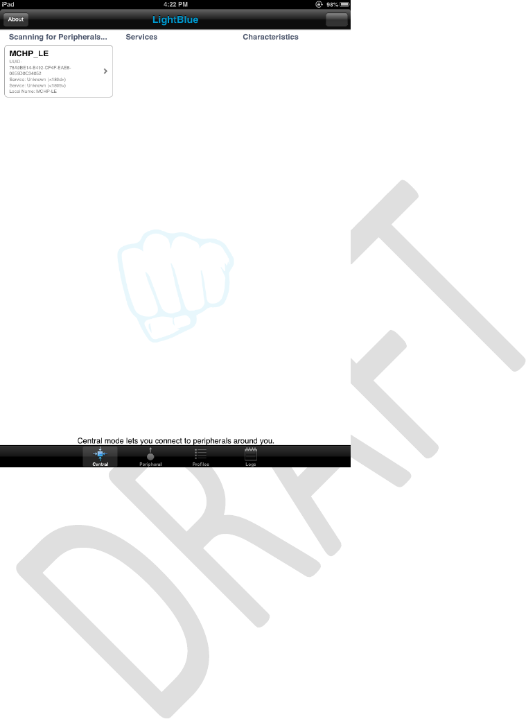
Tap the icon of RN4020, the two devices should be connected. From LightBlue
window, service “180A” and “180F”, UUIDs of Device Information and Battery
services respectively should be seen. From terminal emulator, type command “B” to
bond two devices. Apple device will ask if pairing is permitted. Allow pairing to
bond two devices together. Bonding is optional. Tap the icon with label “180A”
should display 7 additional UUIDs for characteristics of Device Information service.
Tab any of the 7 characteristic UUID to display the characteristic window. A button
with label “Read” allows user to read the current setting of those characteristics.
Figure 4 shows snap shot of LightBlue that reads Model Number String of RN4020 in
Device Information service.
Figure 4: Reading Model Number String in Device Information Service
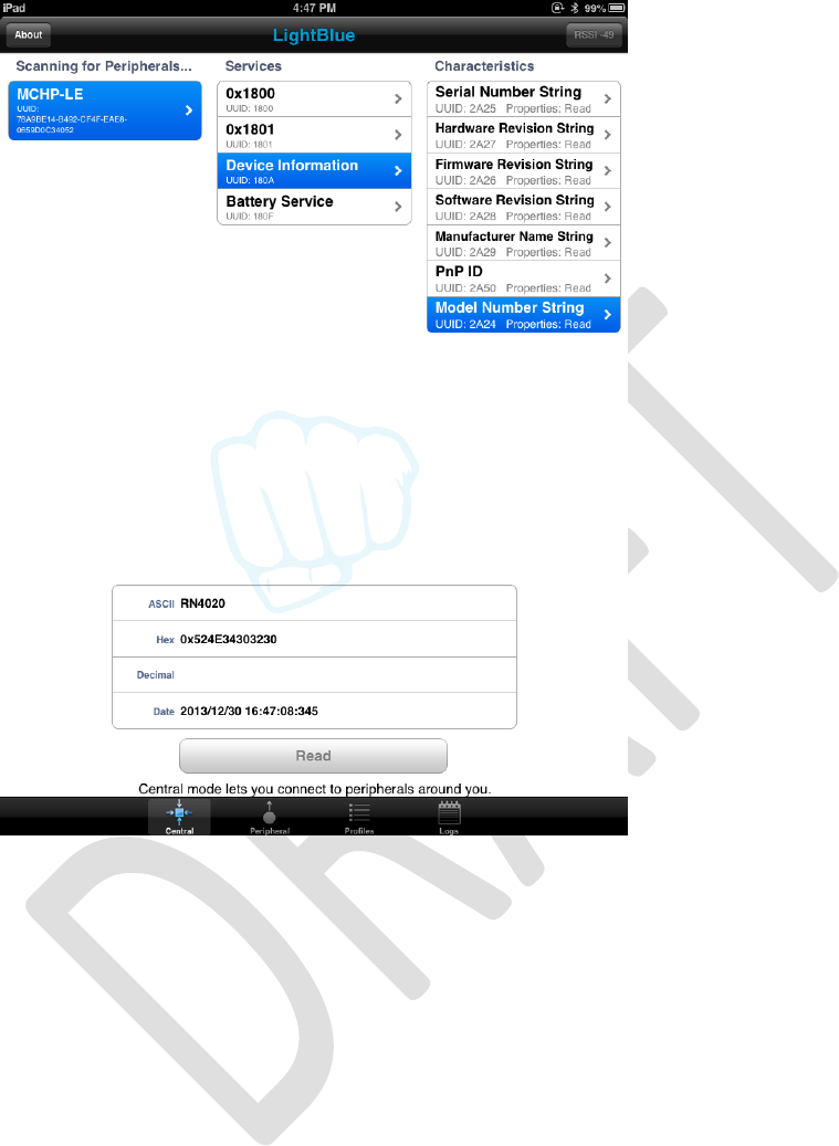
Now tap the UUID “180F” that will show one characteristic Battery Level with UUID
“2A19”. After tapping icon “2A19”, characteristic windows shows that this
characteristic’s property: readable and notification could be started.
Now go back to terminal emulator to control RN4020 directly. We need to set the
battery level to be 99% by either of these following commands:
SUW,2A19,63
SHW,001A,63
The first command sets value of characteristic Battery Level to be 99 (0x63) by
addressing its UUID 0x2A19.
The second command sets the value of characteristic Battery Level to be 99 (0x63)
by addressing its handle 0x001A. The match between handle and UUID could be
found by command “LS”. The handle value for each characteristic stays the same for
the same set of server service setting. As long as supported server services are not
changed by command “SS”, the handles of characteristics stay the same.
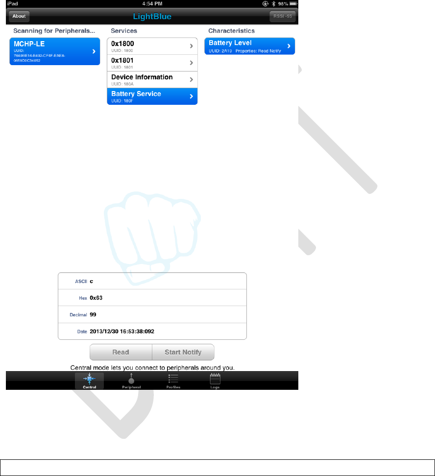
Now from LightBlue window, if we tap the “Read” button for UUID 0x2A19, the
returned value should show 63 in hex and 99 in decimal. Figure 5 shows the reading
of Battery Level in Battery Service:
Figure 5: Reading Battery Level in Battery Service
LightBlue could also start notification on Battery Level characteristic by click button
“Start Notify” within LightBlue window. On RN4020 side, a notification should be
output to the screen shows as follows:
WC,180F,2A19,0002,0100
It means that LightBlue tried to write 2 octets value 0x0001 (little endian over air
makes it 0100) to configuration handle of Battery Level characteristic with UUID
0x2A19 in Battery Service with UUID 0x180F, effectively enabling notification for
this characteristic. (Check Bluetooth Core Specification Volume 3, Part G, section
3.3.3.3 table 3.11 for details)
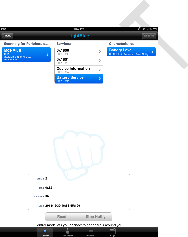
Now we could try to update the battery level to be 50% on RN4020 by typing either
of following commands:
SUW,2A19,32
SHW,0019,32
After issuing either of above commands, user could notice that the value of UUID
2A19 in LightBlue window, running on Apple device automatically updates to 0x32
(50 decimal). This is because with an active notification, any update to the value of a
characteristic on the server side will be notified to the client side. Figure 6 shows
automatic update results on LightBlue.
Figure 6: Notification Result of Battery Level

We could test the private services that user may define on RN4020. The command
procedures and their description could be found below:
SS,C0000001 //Enable private service support.
PZ // Clear the current private service and characteristics
PS,11223344556677889900AABBCCDDEEFF
// Set private service UUID to be 0x11223344556677889900AABBCCDDEEFF
PC,010203040506070809000A0B0C0D0E0F,02,05
// Add private characteristic 0x010203040506070809000A0B0C0D0E0F to
// current private service. The property of this characteristic is 0x02 (readable,
// check table 1) and has maximum data size 5 octets
PC,111213141516171819101A1B1C1D1E1F,18,02
// Add private characteristic 0x111213141516171819101A1B1C1D1E1F to
// current private service. The property of this characteristic is 0x18 (writable
// and could notify. Check table 1) and has maximum data size 2 octets.
U // Unbond to make Apple device discoverable
R,1 // Reboot RN4020 to make the changes effective
+ // Enable echo
LS // list the services on server side. Private service and
// characteristics could be found in the list
Following results should show up for server services:
180A
2A25,000B,V
2A27,000D,V
2A26,000F,V
2A28,0011,V
2A29,0013,V
2A50,0015,V
2A24,0017,V
180F
2A19,001A,V
2A19,001B,C
11223344556677889900AABBCCDDEEFF
010203040506070809000A0B0C0D0E0F,001E,02,05
111213141516171819101A1B1C1D1E1F,0020,08,02
111213141516171819101A1B1C1D1E1F,0021,10,02
END
Since we change the service settings, but LightBlue still caches the old settings, it is
very likely that Apple device needs a complete power cycle to show the new
configuration. Press and hold POWER and HOME button of iOS devices for a few
seconds to perform a complete power down. Press POWER button to power it on
again. After power cycling and launch LightBlue app, the private service and
characteristics could be seen. Figure 7 shows the LightBlue that discovered private
services that we just defined.
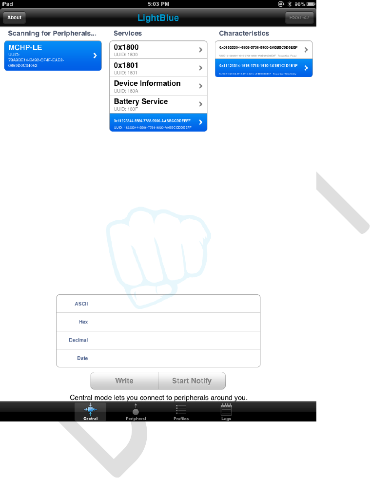
Figure 7: Private Service Discovered by BlueLight
The same as public services such as Device Information and Battery service, those
characteristics could be read, write and get notification by issuing commands as
follows:
SUW,010203040506070809000A0B0C0D0E0F,1234
// Set value 0x3412 to characteristic
// 0x010203040506070809000A0B0C0D0E0F
SHW,001E,5678 // Set value 0x7856 to handle 0x001E, which is associated
// with characteristic
// 0x010203040506070809000A0B0C0D0E0F
LightBlue could then read the value of characteristic
0x010203040506070809000A0B0C0D0E0F, as show in Figure 8
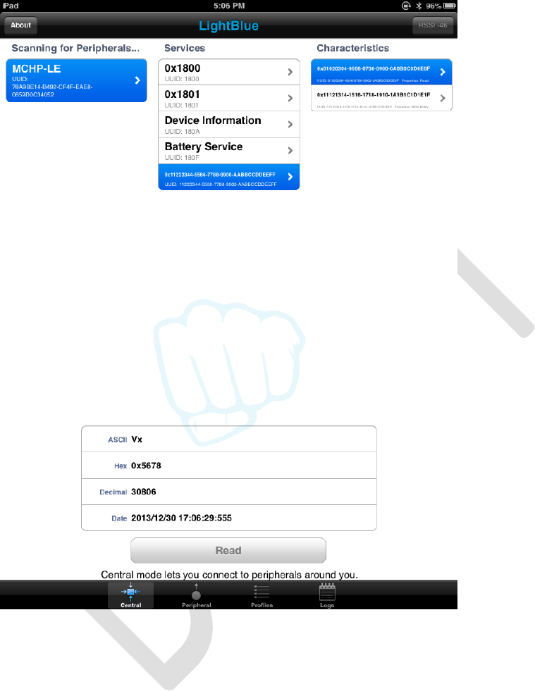
Figure 8: Reading Private Characteristic
LightBlue could also write or start notification on characteristic
0x111213141516171819101A1B1C1D1E1F. The effect is the same as operating on
a public characteristic. The only difference to RN4020 user is that public
characteristic has short 16-bit UUID, while private characteristic has long 16-byte
UUID.
Figure 9 shows writing value 0x3412 (little endian) to private characteristic
0x111213141516171819101A1B1C1D1E1F from LightBlue. On terminal emulator
of RN4020 module, following status message will show up, which means the value of
characteristic 0x111213141516171819101A1B1C1D1E1F (with handle 0x0020)
has been written as 0x3412.
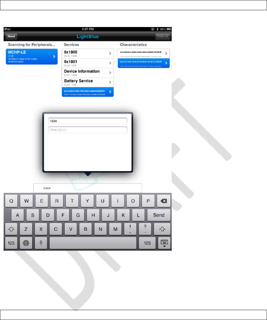
WV,111213141516171819101A1B1C1D1E1F,0020,1234.
Figure 9: Writing Values to Private Characteristics
Notification on private characteristic could also be enabled by pressing “Start
Notify” button within LightBlue window. RN4020 should notify the host the start of
notification by following status message, which means the configuration of
characteristic 0x111213141516171819101A1B1C1D1E1F has been written as
0x0001 (little endian), therefore, notification has been started.
WC,111213141516171819101A1B1C1D1E1F,0021,0100.
Once notification has been started, value of private characteristic could be updated
from RN4020 and the updated value will be shown on LightBlue automatically. Try
following command to update the value of private characteristic:
SUW, 111213141516171819101A1B1C1D1E1F,AB90
// Set value 0x90AB to characteristic
// 0x111213141516171819101A1B1C1D1E1F
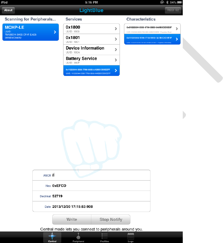
SHW,0020,EFCD // Set value 0xCDEF to handle 0x0020, which is associated
// with characteristic
// 0x111213141516171819101A1B1C1D1E1F
User should see that the value of private characteristic
0x111213141516171819101A1B1C1D1E1F is updated automatically to 0x90AB
and 0xCDEF respectively, as shown in snapshot in Figure 10.
Figure 10: Notification to Private Characteristic
4.3 Demonstration between two RN4020 Modules
BTLE functionality could also be demonstrated between two RN4020 modules. In
this setting, one RN4020 must act as central role and other as peripheral role. We
are also going to demonstrate the services as server and client roles.

First we need to configure a RN4020 module to be in central role. For simplicity, we
call it Module A. Following commands are issued to configure such device:
Assert GPIO 3 to be low to enter command mode
Open a terminal emulator that connects to the serial port of Module A with
following parameters:
o baud rate: 115200
o data bits: 8
o parity: none
o stop bits: 1
o flow control: hardware
+ // turn echo on
SF,1 // factory reset
SS,C0000000 // Support Device Info and Battery as server
SR,D200 // Set device as central, buffered read and support MLDP and
// UART flow control
R,1 // reboot to make changes effective
Then, we need to configure another RN4020 module to be in peripheral role. For
simplicity, we called it Module B. Following commands are issued to configure such
device:
Assert GPIO 3 to be low to enter command mode
Open a terminal emulator that connects to the serial port of Module A with
following parameters:
o baud rate: 115200
o data bits: 8
o parity: none
o stop bits: 1
o flow control: hardware
+ // turn echo on
SF,1 // factory reset
SS,30000000 // Support Heart Rate and Health Thermometer services as
// server. Notice that server services in module B overlaps
// client services in module A
SR,7200 // Set device as peripheral, buffered read, automatic
// advertisement, support MLDP and flow control features
R,1 // reboot to make changes effective
When module B is powered up, it automatically starts advertisement since auto
advertisement feature is enabled with command “SR”. Module A then could try to
connect to module B by following way:
F // Start scan
The scan result should be shown up quickly as following, where the three
elements are MAC address, MAC address type and device name respectively.

00035B0358E6,Public,MCHP-LE
X // Stop scanning
E,0,00035B0358E6 // try to establish connection with device of public MAC
// address 0x00035B0358E6. See section 3.3.2.5 for
// details of command “E”.
Once connected, message “Connected” will be shown on the terminal emulators of
both devices. Then we can check the server and client services on both modules:
From Module A:
LS // List server services
LC // List client services
Server Services
Client Services
180A
2A25,000B,V
2A27,000D,V
2A26,000F,V
2A28,0011,V
2A29,0013,V
2A50,0015,V
2A24,0017,V
180F
2A19,001A,V
2A19,001B,C
END
180D
2A37,000B,00
2A37,000C,10
2A38,000E,02
2A39,0010,08
1809
2A1C,0013,00
2A1C,0014,20
2A1D,0016,02
END
From Module B:
LS // List server services
LC // List client services
Server Services
Client Services
180D
2A37,000B,V
2A37,000C,C
2A38,000E,V
2A39,0010,V
1809
2A1C,0013,V
2A1C,0014,C
2A1D,0016,V
END
180A
2A25,000B,02
2A27,000D,02
2A26,000F,02
2A28,0011,02
2A29,0013,02
2A50,0015,02
2A24,0017,02
180F
2A19,001A,02
2A19,001B,10
END

User should notice that the server services on Module A match client services on
Module B and vice versa. So that data exchange between Module A and B could
follow client-server module where server maintains the data and client access to the
data.
From Module A, Battery Service is server service, so we could set battery level to be
100% by either of following commands as server services access:
SUW,2A19,64 // Set Battery Level (UUID 0x2A19) to be 100
SHW,001A,64 // Set Battery Level (handle 0x001A) to be 100
From Module B, Battery service is client role, we could read battery level from
server service on module A by following commands as client access:
CURV,2A19
CHR,001A
Both commands will return the value of Battery Level characteristic 0x2A19 to be
100 as follows:
R,64.
The output means the characteristic read returns data of 1 octet in length and value
of 0x64.
From Module B, notification could be started by issuing either of following
commands:
CUWC,2A19,1
CHW,001B,0100
Client service command “CUWC” writes configuration of UUID 0x2A19 to be
notification enabled. Client service command “CHW” writes value 0x0001 (little
endian format) to handle 0x001B, which corresponds to characteristic UUID of
0x2A19. According to Bluetooth Core Specification Volume 3, Part G, section 3.3.3.3
table 3.11, value 0x0001 means start notification.
Once notification is successfully started, Module A will notify host the event with
following format:
WC,180F,2A19,0002,0100.
It means the configuration for primary service 0x180F (Battery Service),
characteristic 0x2A19 (Battery Level) has been written by 2 octets with value
0x0001 (little endian format), or means notification has started. If Battery Level

characteristic has been set value before, a notification will be sent to Module B
automatically.
Once notification is successfully started, and Battery Level characteristic has been
set value before, a notification will be received by Module B with following format:
Notify,180F,2A19,64.
It means that the value of characteristic 0x2A19 (Battery Level) in primary service
0x180F (Battery Service) has been updated to be 0x64.
After notification starts, value change on Battery Level on Module A will be updated
on Module B. Try either of following commands on Module A and check automatic
updates on Module B.
SUW,2A19,5A // Set Battery Level to be 90% on Module A
SHW,001A,50 // Set Battery Level to be 80% on Module A
Similar operations could be performed on Heart Rate or Health Thermometer
services, where Module B sets the values and Module A reads values.
Once access of characteristics in public services has been verified, then we could
start MLDP service. Microchip MLDP service is built on top of private service but
acts transparently to the user. To use MLDP service between two RN4020 devices,
both devices must enable MLDP with proper parameters in command “SR” (Check
section 3.2.1.12 for details of command “SR”). MLDP mode could only be started
when two RN4020 modules both have MLDP enabled and are connected together.
To start MLDP mode, simply assert GPIO 4 to be high. RN4020 will output “MLDP” to
indicates the start of MLDP mode. Once in MLDP mode, any data from UART will be
sent to the peer device. When receiving MLDP data from the peer, if
AUTO_MLDP_DISABLE feature is not enabled (Check section 3.2.1.12 for command
“SR”), RN4020 will automatically enter MLDP mode; otherwise, all data will be
ignored until GPIO 4 is set high to enter MLDP mode.
From Module A, assert GPIO 4 to be high and wait until “MLDP” output to the
terminal emulator. Type anything on the terminal emulator of Module A, you should
see that terminal emulator of Module B output “MLDP” first to enter MLDP mode
and then output whatever user typed on terminal of Module A. User could also try to
type on terminal emulator of Module B and expects the same output on terminal
emulator of Module A.
To exit from MLDP mode, set GPIO 4 to be low and “CMD” should show on the
terminal emulator to indicate that RN4020 is put into command mode again. Now,
set GPIO 4 to be low on Module B (GPIO3 and GPIO4 have weak pull down resistors,

so they will stay low if not pull high). Then try to disable notification on Battery
Level by either of following commands:
CHW,001B,0000
CUWC,2A19,0
On Module A, status change should be notified to the host. However, Module A
currently is in MLDP mode, only output MLDP data to the UART. Instead, GPIO 6 will
be set high (Red LED lights up on RN4020 EVB board) to indicate status message
pending to output. Once GPIO 4 is put to be low to enter command mode, the status
message will be output to the UART. Maximum status message that could be hold is
256 octets.
4.4 Demonstration of RN4020 Scripting Capability
In this section, a step-by-step guide is provided to demo the capability of scripting
on RN4020.
4.4.1 Setting up Private Service and Characteristics
Scripting function is best to work with private service and characteristics. The main
input/output peripherals in scripting are analogue or digital ports. Public services
and characteristics pre-defined data format that may not always work with the
reading or outputting of RN4020 ports. Private service and characteristics, on the
other hand, could define data format freely, therefore, peer device of the BLE
connection is able to take over data interpolation functionality without evolvement
of device that runs scripts.
Following AT commands over UART set up the private service and characteristics
+ // Echo on
SF,1 // Factory Reset
SS,00000001 // Enable private service
SR,4000 // Enable buffer read
PZ // Clean private Service
PS,123456789012345678901234567890FF // Set private service uuid
PC,12345678901234567890123456789011,12,02 // Set private characteristic to
be readable, notifiable and 2 octets in length
PC,12345678901234567890123456789022,02,02 // Set private characteristic to
be readable and 2 octets in length
R,1 // Reboot
After rebooting, we could use command “LS” to check the server characteristics:

123456789012345678901234567890FF
12345678901234567890123456789011,000B,02,02
12345678901234567890123456789011,000C,10,02
12345678901234567890123456789022,000E,02,02
4.4.2 Script Input
Then we start to write the script by clearing the script and enter script input mode
with following commands:
WC // Clean script
WW // Enter script input mode
We need to input following script. After finish entering script, type “ESC” key to exit.
@PW_ON
# start advertisement
A
# define range of variable $VAR1
$VAR1 < “0300”
# associate handle 0x000E to reading of AIO1
%000E = G@,1
@CONN
# set timer 1 to be around 5 seconds
SM,1,00500000
@TMR1
# read AIO0
$VAR1 = G@,0
# set handle 0x000B to the AIO0 value
SHW,000B,$VAR1
# restart timer
SM,1,00500000
After powering on, event @PW_ON is generated. The script will first start
advertisement. Then it defines the range of $VAR1 to be less than 0x0300. Finally, it
associates handle 0x000E to the analogue port AIO1, which is the temperature
sensor.
Once connection is established, event @CONN is generated. The script sets up timer
1 to expire in roughly 5 seconds.

Once timer 1 is expired, event @TMR1 is generated. AIO0, which is the light sensor,
is read and the value is assigned to $VAR1. If the reading is within the predefined
range (less than 0x0300), then the value is written to handle 0x000B; otherwise,
handle 0x000B is not updated.
If user would like to debug the script, command “WR,<0-6>” could be used.
4.4.3 Running Script
Now, let’s run this script by enabling script after power on with following command:
SR,4100 // Run script after power on
R,1 // Reboot
After rebooting, the script should be running. User could open LightBlue app and
connect to RN4020 module. Click the characteristic
0x12345678901234567890123456789011 and start notify.
For every five seconds, AIO0 (the light sensor) will be read. If the light sensor is
exposed to light, the reading is around 0x0500, outside the range of $VAR1.
Therefore, handle 0x000B is never updated and notification is never sent. However,
if user block the light sensor, the reading should be within the range of $VAR1,
therefore, the value of the characteristic in LightBlue will be updated every 5
seconds.
On the other hand, for characteristic 0x12345678901234567890123456789022,
user could read its value from LightBlue app. Since the corresponding handle
0x000E has been associated with AIO1, so reading on handle 0x000E will return the
reading of AIO1 (the temperature sensor) without involvement of a host MCU.
In this demo, the script runs the RN4020 module and performed tasks
independently. It shows that for a simple application like this, RN4020 module could
run stand-alone and a host MCU could be saved.
All transmitters regulated by FCC must comply with RF exposure requirements. KTB
447498 General RF Exposure Guideline provides guidance in determining whether
proposed or existing transmitting facilities, operations or devices comply with limits
for human exposure to Radio Frequency (RF) fields adopted by the Federal
Communications Commission (FCC).
