MINEW TECHNOLOGIES MS49SF2 BLE Module User Manual
SHENZHEN MINEW TECHNOLOGIES CO., LTD. BLE Module
User Manual
TEL: +86-755-8886 8480 FAX: +86-755-2982 5342 EMAIL: sales@minewtech.com URL: wwwminewtech.com
Page 1
Minew Technologies
Bluetooth 4.0 Module
Instructions V1.0
Description
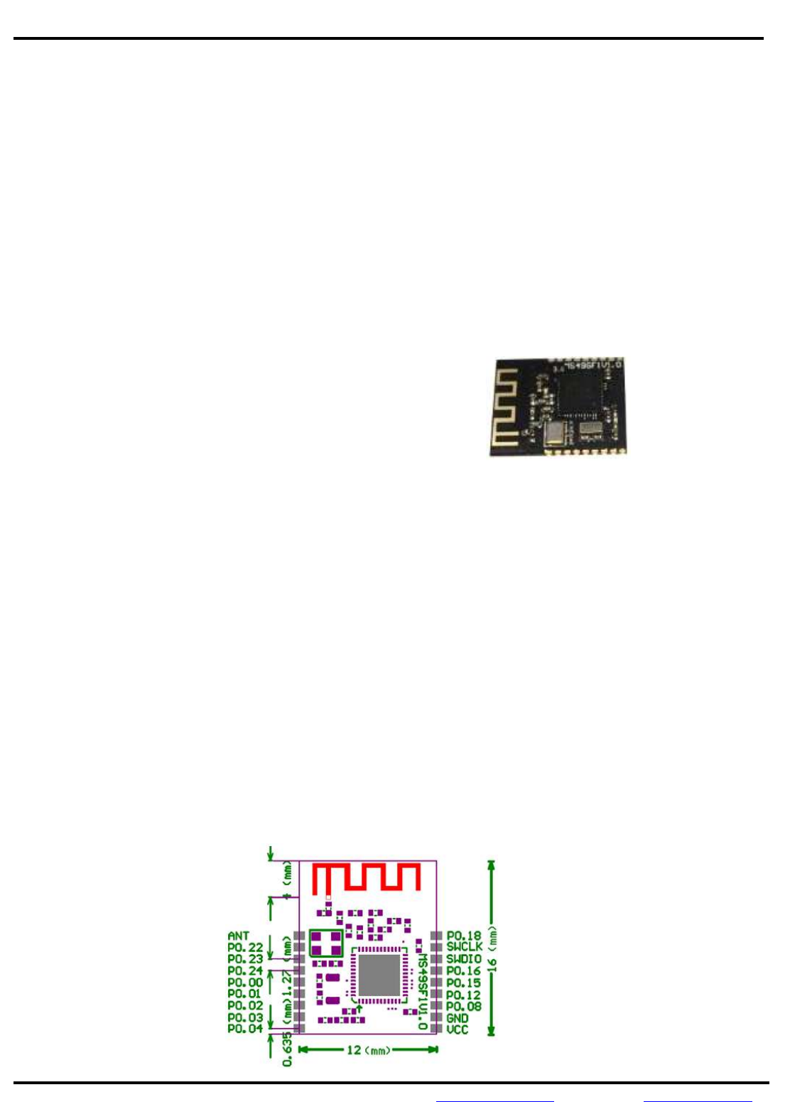
The MS49SF2 Bluetooth 4.0 low energy module is a SMD package module basis Nordic nRF51822 chip, it is a
smart module with cost-effective, ultra low power, true system-on-chip (SoC) for Bluetooth low energy
applications. It enables robust BLE master or salve nodes to be built with very low total bill of material costs.
The MS49SF2 smart BLE 4.0 module combines an excellent RF transceiver with an ultra low energy ARM
Cortex0, in-system programmable 256KB flash memory and many powerful supporting features and peripherals.
It is suitable for systems where ultra low power consumption is required.
Features
- Bluetooth low energy technology compatible
- Excellent link budget (up to 97dB)
- Enable long range applications
- Accurate digital RSSI
- Compatible with CE and FCC regulation
- Ultra low energy ARM core chip
- Battery monitor and temperature sensor
- Samples application and profiles
- Full speed USB interface
- AES security coprocessor
Application
- 2.4GHz Bluetooth low energy systems
- Mobile phone accessories
- Sports and leisure equipment
- Consumer electronics
- Human interface devices (keyboard, mouse, remote control and etc.)
- USB dongles
- Healthcare and medical
Mechanical Footprint (Unit: mm)
MS49SF2
TEL: +86-755-8886 8480 FAX: +86-755-2982 5342 EMAIL: sales@minewtech.com URL: wwwminewtech.com
Page 2
Minew Technologies
Bluetooth 4.0 Module
Instructions V1.0
Pin Description
Pin Symbol
Definition Description Remark
VDD --- Positive of power supply 1.8~3.6Vdc
GND --- Negative of power supply ---
P0.01 CMD Data / Command Data=1, Command=0
P0.02 SLP Sleeping / Waken Sleeping=1, Waken=0
P0.03 BTX Send the data to external MCU MS49SF2’s TX
P0.04 BRX Receive the data from external MCU MS49SF2’s RX
P0.08 LED1 Connection status indication Active Low
P0.12 LED2 Command status indication Active Low
P0.15 RST Reset Active Low
Electronic Parameters
Item Test Data Remarks
Operation Voltage 1.8~3.6V DC
Operation Frequency 2400-2483.5MHz Programmable
Frequency Error +/- 20KHz ---
Transmission Power -30~+4dBm Adjustable
Receiving Sensitivity -93dBm ---
Receiving Current 13mA Standard mode
Transmission Current 16mA @+4dBm
7mA @-8dBm
Sleep consumption 0.4uA Power mode 3, connection-less state
Transmission distance 50 meters BER<0.1%, Open space
Antenna 50ohm Null
Dimension 16*12*2.0mm Null
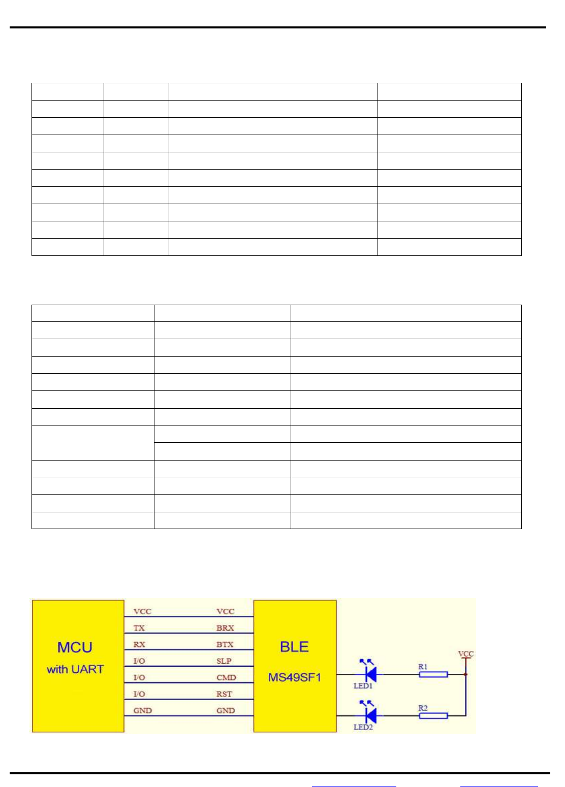
Typical Application

TEL: +86-755-8886 8480 FAX: +86-755-2982 5342 EMAIL: sales@minewtech.com URL: wwwminewtech.com
Page 3
Minew Technologies
Bluetooth 4.0 Module
Instructions V1.0
Default Setting
Role of Module: Slave; Module Name: Minew;
Baud Rate: 9600bps, 8N1; Broadcasting time: 1 Second;
Minimum circle of connection: 7.5mS; Maximum circle of connection: 60mS;
Transmission Power: 0dBm; Maximum disconnection time: Disable
Command Format
Format: Head (1 byte) + Data Length (1 byte) + Command code (1 byte) + Data
Head: 0x88, it is a fixed value.
Data Length: It doesn’t include the length of head, data length and command code.
Data: All the parameters’ value.
When CMD is low, the BLE module works on the Command Mode and UART sends the command code.
When CMD is high, the BLE module works on the Data Mode and UART sends transparent data.
Moreover, when CMD and SLP are low, the command code will be available.
1. Set Module Name (Command code: 0x01)
The maximum length of module name is 15 bytes.
For example, let’s change the module name to ABCD.
Then, the correct command code is 88 [04] 01 [41 42 43 44].
88: Head;
04: Data length, 4 bytes (ABCD);
01: Command code;
41 42 43 44: Data “ABCD” in hex;
If the setting is successful, the BLE module will send back the command code 88 04 01 41 42 43 44 to the MCU,
and the LED2 will flash one time. Otherwise, the setting was failure.
2. Set Broadcasting Time (Command code: 0x02)
The maximum broadcasting time is 1500mS, the minimum step is 100mS.
0x01: 100mS, 0x02: 200mS, 0x03: 300MS…..0x0F: 1500mS.
For example, let’s change the broadcasting time to 1200mS.
Then, the correct command code is 88 02 02 [0C] AA.
If the setting is successful, the BLE module will send back the command code 88 02 02 0C AA, and the LED2 will
flash one time. Otherwise, the setting was failure.
TEL: +86-755-8886 8480 FAX: +86-755-2982 5342 EMAIL: sales@minewtech.com URL: wwwminewtech.com
Page 4
Minew Technologies
Bluetooth 4.0 Module
Instructions V1.0
3. Set Disconnection Time (Command code: 0x03)
The default disconnection time is disabled; the range is from 0 to 250 seconds.
0x01: 1 second, 0x02: 2 seconds, 0x03: 3 seconds...0x0A: 10 seconds…0x1E: 30 seconds…
If it is disabled, the corresponding command code is 88 02 03 [00] AA.
For example, let’s change the disconnection time to 10 seconds.
Then, the correct command code is 88 02 03 [0A] AA.
If the setting is successful, the BLE module will send back the command code 88 02 03 0A AA, and the LED2 will
flash one time. Otherwise, the setting was failure.
4. Set Transmission Power (Command code: 0x04)
The default transmission power is 0dBm; the range is from -20dBm to +4dBm.
Please refer to the below table.
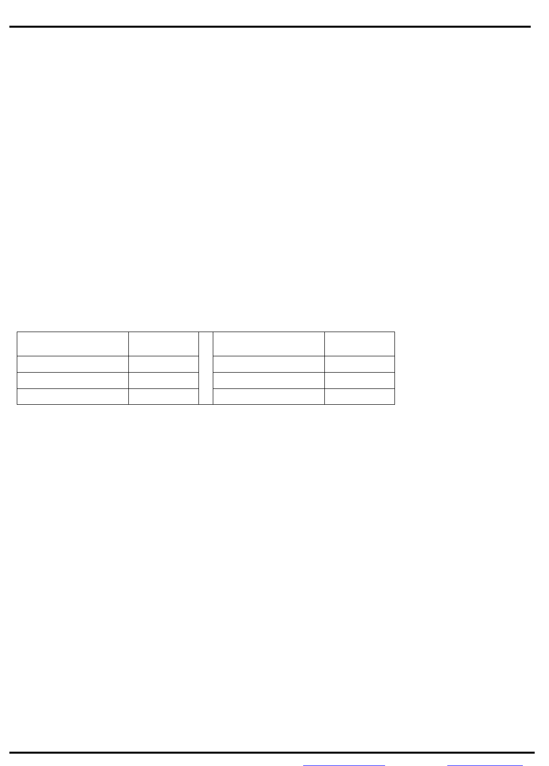
Transmission Power Value
Transmission Power Value
+4dBm 0x01 -8dBm 0x04
0 0x02 -12dBm 0x05
-4dBm 0x03 -20dBm 0x06
For example, let’s change the transmission power to -8dBm.
Then, the correct command code is 88 02 04 [04] AA.
If the setting is successful, the BLE module will send back the command code 88 02 04 04 AA, and the LED2 will
flash one time. Otherwise, the setting was failure.
5. Query Module Name (Command code: 0x11)
Command Code: 88 04 11 AA AA.
If the command is executed successful, the module will send back the command code 88 04 11 [41 42 43 44] and
the LED2 will flash one time. Otherwise, the command was failure.
5. Query Broadcasting Time (Command code: 0x12)
Command Code: 80 02 12 AA AA.
If the command is executed successful, the module will send back the command code 88 02 12 [xx] AA and the

TEL: +86-755-8886 8480 FAX: +86-755-2982 5342 EMAIL: sales@minewtech.com URL: wwwminewtech.com
Page 5
Minew Technologies
Bluetooth 4.0 Module
Instructions V1.0
LED2 will flash one time. Otherwise, the command was failure.
6. Query Disconnection Time (Command code: 0x13)
Command Code: 80 02 13 AA AA.
If the command is executed successful, the module will send back the command code 88 02 13 [xx] AA and the
LED2 will flash one time. Otherwise, the command was failure.
7. Query Transmission Power (Command code: 0x14)
Command Code: 80 02 14 AA AA.
If the command is executed successful, the module will send back the command code 88 02 14 [xx] AA and the
LED2 will flash one time. Otherwise, the command was failure.
8. Query MAC Address which connected with BLE Module (Command code: 0x14)
Command Code: 80 02 15 AA AA.
If the command is executed successful, the module will send back the command code as following:
88 06 15 [xx xx xx xx xx xx ] AA, and the LED2 will flash one time. Otherwise, the command was failure.
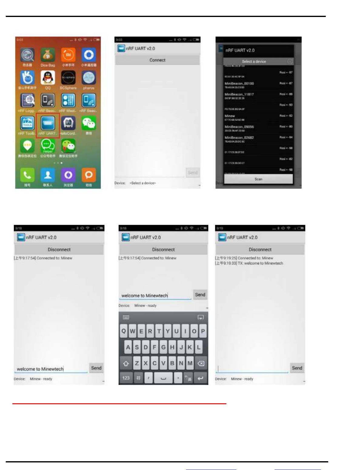
DEMO APP (Android version)
1. Please set the BLE module to Data Mode (CMD=1, SLP=0);
2. Then, run the nRF UART demo APP on the smart phone (Android 4.3+) like below image;
TEL: +86-755-8886 8480 FAX: +86-755-2982 5342 EMAIL: sales@minewtech.com URL: wwwminewtech.com
Page 6
Minew Technologies
Bluetooth 4.0 Module
Instructions V1.0
3. Click the “Connect” and select the BLE module “Minew”;
4. Then, we can send the data from smart phone to the BLE module;
5. You can also use the Serial Port Assistant to debug the BLE module.

TEL: +86-755-8886 8480 FAX: +86-755-2982 5342 EMAIL: sales@minewtech.com URL: wwwminewtech.com
Page 7
Minew Technologies
Bluetooth 4.0 Module
Instructions V1.0
Reference Source Code for the UART Module MS49SF2
void main (void)
{
UartInit(); //UART Initial
MS49SF2Init(); //Transparent Data Mode Initial
while(1)
{
Send_String("minew"); //Send the characters
}
}
void MS49SF2Init(void)
{
unsigned char Set_Name[8]={0x88,0x05,0x01,0x4D,0x69,0x6E,0x65,0x77};
//Set BLE module name: Minew
unsigned char Set_Broadcast_Time[5]={0x88,0x02,0x02,0x0A,0xAA};
//Set Broadcasting time: 1000mS
unsigned char Set_Disconnect_Time[5]={0x88,0x02,0x03,0x0A,0xAA};
//Set Disconnection Time: 10 seconds
unsigned char Set_Send_Power[5]={0x88,0x02,0x04,0x02,0xAA};
//Set Transmission Power: 0dBm
Send_String_Data(Set_Name,8);
Send_String_Data(Set_Broadcast_Time,5);
Send_String_Data(Set_Disconnect_Time,5);
Send_String_Data(Set_Send_Power,5);
}
FCC Caution:
Any changes or modifications not expressly
approved by the party responsible for compliance could void the user's
authority to operate this equipment.
This device complies with Part 15 of the FCC Rules.
Operation is subject to the following two conditions: (1) This device may not
cause harmful interference, and (2) this device must accept any interference
received, including interference that may cause undesired operation.
This device and its antenna(s) must not be co-located or operating in conjunction
with any other antenna or transmitter.
15.105 Information to the user.
(b) For a Class B digital device or peripheral, the instructions furnished the
user shall include the following or similar statement, placed in a prominent
location in the text of the manual:
Note: This equipment has been tested and found to comply
with the limits for a Class B digital device, pursuant to part 15 of the FCC Rules.
Tel:86-755-26066032 Fax:26002892 Web site:www.netopsun.com 8 / 8
These limits are designed to provide reasonable protection against harmful
interference in a residential installation. This equipment generates, uses and
can radiate radio frequency energy and, if not installed and used in
accordance with the instructions, may cause harmful interference to radio
communications. However, there is no guarantee that interference will not
occur in a particular installation. If this equipment does cause harmful
interference to radio or television reception, which can be determined by
turning the equipment off and on, the user is encouraged to try to correct the
interference by one or more of the following measures:
—Reorient or relocate the receiving antenna.
—Increase the separation between the equipment and receiver.
—Connect the equipment into an outlet on a circuit different from that to which
the receiver is connected.
—Consult the dealer or an experienced radio/TV technician for help.
This equipment complies with FCC radiation exposure limits set forth for an uncont
rolled environment.
Radiation Exposure Statement:
This equipment complies with FCC radiation exposure limits set forth for an
uncontrolled environment.
This transmitter must not be co-located or operating in conjunction with any other
antenna or transmitter.
The availability of some specific channels and/or operational frequency bands
are country dependent and are firmware programmed at the factory to match
the intended destination.
The firmware setting is not accessible by the end user.
The final end product must be labelled in a visible area with the following:
“Contains Transmitter Module 2ABU6-MS49SF2”
In the event that these conditions can not be met (for example certain laptop configurations
or co-location with another transmitter), then the FCC authorization is no longer considered
valid and the FCC ID can not be used on the final product. In these circumstances, the OEM
integrator will be responsible for re-evaluating the end product (including the transmitter) and
obtaining a separate FCC authorization