MIP Telecom COMBOX VoIP Gateway User Manual Combox Eng ver1
MIP Telecom Inc. VoIP Gateway Combox Eng ver1
Users Manual
WWW.MIPTEL.COM
MIP0201000B
1
Combox™User Manual
(Preliminary Release)
Multi-services over Internet Protocol

WWW.MIPTEL.COM
MIP0201000B
2
MIP Telecom Standalone VoIP Gateway
Model Combox™
H.323 / SIP Dual Mode
Quick Start Guide
MIP Telecom Combox™
This publication may not be reproduced, in whole or in part, without prior expressed
written permission from MIP Telecom, Inc. All rights reserved.
Copyright ©2002, by MIP Telecom, Inc.
MIP Telecom, Inc. makes no representations or warranties withrespect to the contents
hereof and specifically disclaims any implied warranties of merchantability or fitness for
any particular purpose.
Furthermore, MIP Telecom, Inc. reserves the right to revise this publication and to make
changes from time to time in the content hereof without obligation of MIP Telecom, Inc.
to notify any person or organization of such revisions or changes.
Record of Revisions
Revision Description
A Initial Release.
(04/15/02)
TRADEMARK
Trademarks of MIP Telecom, Inc. are the MIP Telecom and MIP Telecom Combox™
logo.
Windows is registered trademarks of Microsoft.
MIP Telecom, Inc.
2F KMIT Building 829-1 Yeoksam 1 Dong Gangnam Gu, Seoul
Korea, 135-936
Phone: (82) 2-557-3399
Fax: (82) 2-554-3303
http://www.miptel.com

WWW.MIPTEL.COM
MIP0201000B
3
Contents
Introduction ……………………............................................. 4
Related Documentation ............................................................ 5
Installing Your Combox™ ....................................................... 5
Installing and Configuring Your Combox™............................ 5
Unpacking Your Combox™..................................................... 6
Cabling Your Combox™.......................................................... 6
Cabling Procedure ……............................................................ 6
Configuring Your Combox™................................................... 8
Combox™Configuration........................................................ 10
Limited Warranty ................................................................... 15
Technical Support ................................................................... 15
FCC Declaration …................................................................. 16
WWW.MIPTEL.COM
MIP0201000B
4
Combox™Quick Start Guide
Introduction
Welcome to MIP Telecom's stand-alone VoIP Gateway, the Combox™ .
The Combox™allows analog voice and fax communication over an IP network.
MIP Telecom’s voice/fax gateway technology allows voice/fax communication
to be transmitted, with no additional expense, over your existing IP network,
which has traditionally been data-only. To access this free voice and fax
communication, all you have to do is connect the Combox™to your telephone
equipment, and then to your existing Internet connection. Once configured, the
Combox™then allows voice and fax to travel down the same path as your
traditional data communications.
The Combox™ supports the H.323 and SIP standards-based protocolenabling
your Combox™to communicate with other third-party VOIP Gateways or other
endpoints that support the H.323/SIP protocols, such as Microsoft MSN
Messenger.
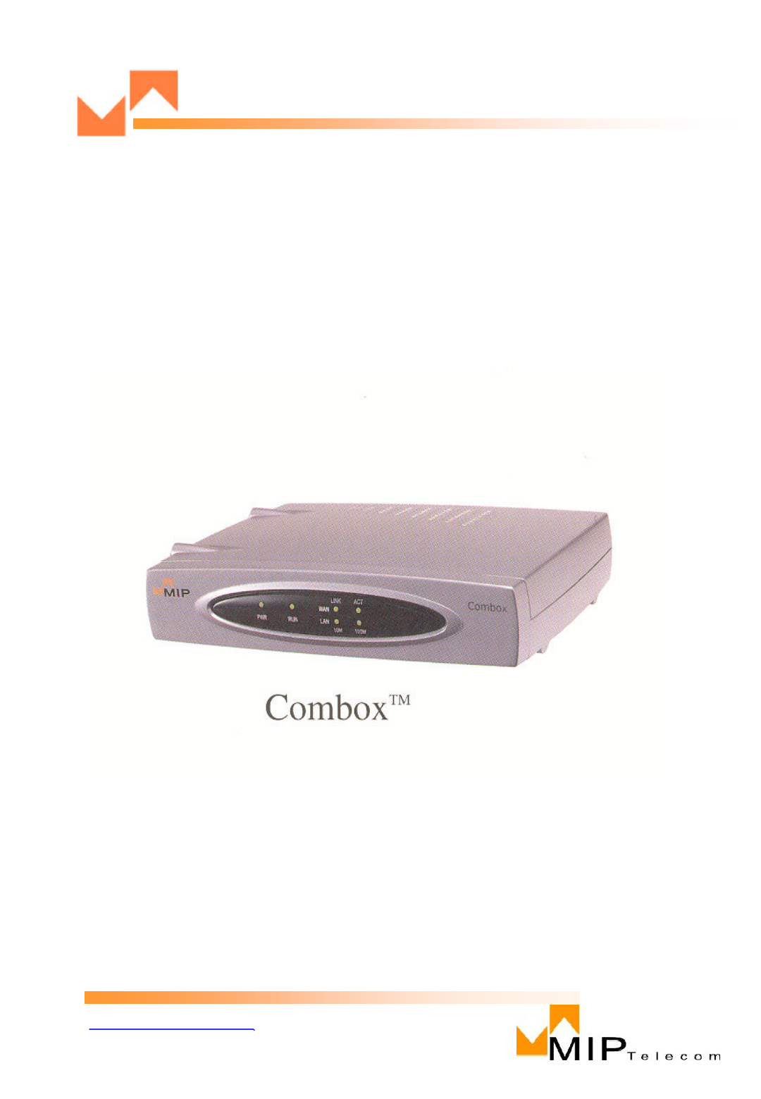
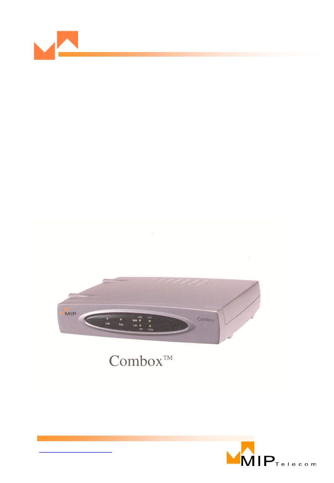
< Figure 1. Combox™ >

WWW.MIPTEL.COM
MIP0201000B
5
Introduction
The Combox™has one PSTN, one Phone Line, a 10 Mbps Ethernet LAN interface, and an
WAN port.
Related Documentation
The Combox™Quick Start Guide is intended to be used by General users.
This Quick Start Guide provides the necessary information for an end user to unpack, cable,
load, and configure the unit for proper operation.
The detailed MIP Telecom Combox™User Guide which provides in-depth information on the
features and functionality of MIP Telecom’s Combox™. is available from MIP Telecom’s
Web site:
http://www.miptel.com
Viewing and printing a user guide from the Web also requires that you have the Acrobat
Reader loaded on your system. To select the Combox™User Guide from the MIP Telecom
home page.
VOIP Quick Start Guide
Installing Your Combox™
The basic steps of installing your Combox™network involve unpacking the units, connecting
the cables, and configuring the units thru web browser. This process results in a fully
functional Voice Over IP network. A brief description is provided below withdetailed
instructions provided later.
Installing and Configuring Your Combox™
The user must first configure each Combox™for its specific function.
During the configuration process, it’s important to note that the Phone Directory is configured
differently depending onwhether or not you have Gatekeeper support on your VOIP network.
If your VOIP network supports a H.323 Gatekeeper, you must register all H.323 endpoints
with the Gatekeeper. If your VoIP network supports a SIP server, you must register all SIP
UAs with the SIP server.
WWW.MIPTEL.COM
MIP0201000B
6
Cabling
Cabling Your Combox™
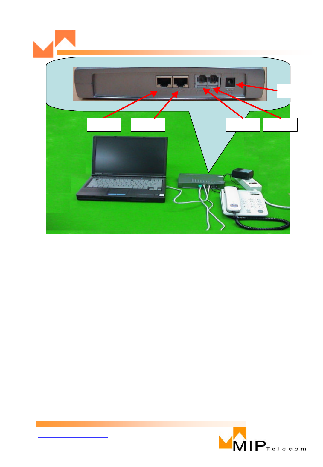
Cabling your Combox™involves making the proper Power,
WAN Port, LAN connection, PSTN and Phone. Figure 2.2 shows the back panel
connectors and the associated cable connections.
The Cabling Procedure section provides step-by-step instructions for cabling
your Combox™ .
Cabling Procedure
1. Using the supplied cable, connect the power supply to a live AC outlet, then
plug the power supply into the Combox™as shown in Figure 2.2.
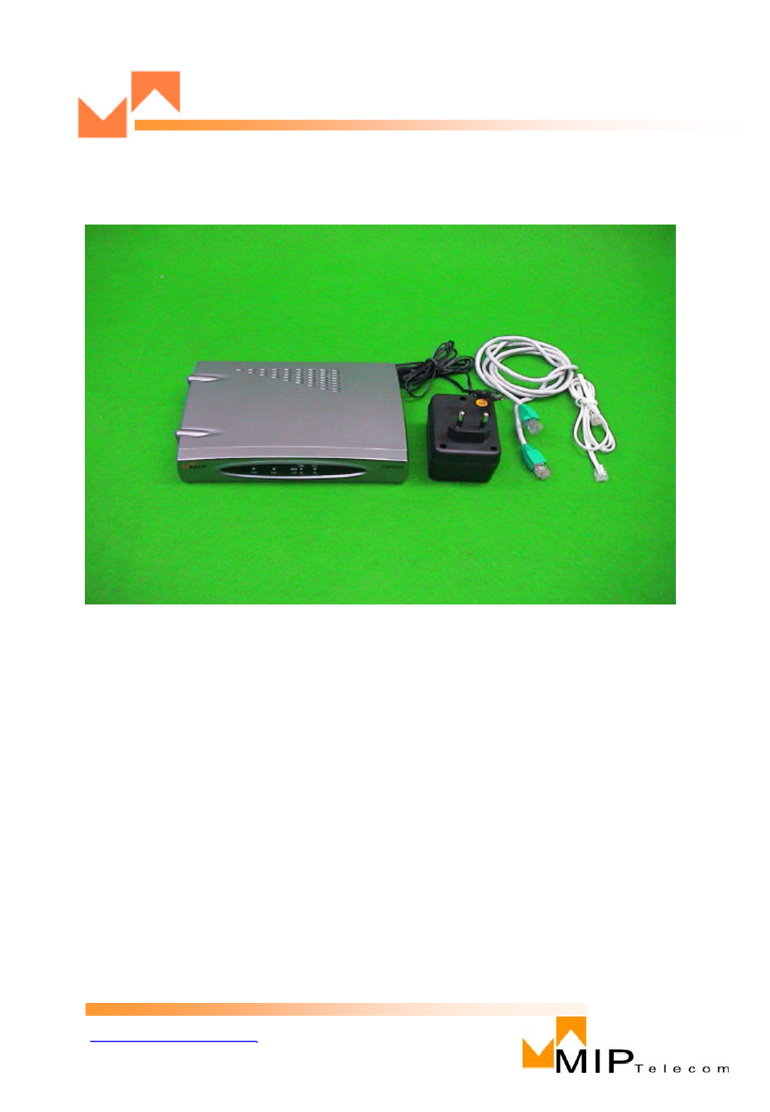
< Figure 2. Unpacking >
Unpacking Your Combox™
Remove all items from the box. (See Figure 2.)
WWW.MIPTEL.COM
MIP0201000B
7
2. Connect the Combox™to a PC using the RJ-45 cable provided with your unit. Plug the
RJ-45 end of the cable into the LAN port of the Combox™and connect the other end to
the PC’s LAN port (Figure 2.2).
3. Connect a network cable to the WAN connector on the back of the Combox™. Connect
the other end of the cable to your network.
4. Connect a RJ-11 cable to the Line and the other end to the PSTN. If you are connecting a
station device such as an analog telephone, fax machine, or Key Telephone System (KTS)
to your Combox™, connect an RJ-11cable to the Phone connector on the back of the
Combox™and the other end to the station device.
5. Turn on power to the Combox™by plugging-in the adaptor. Wait for the Boot LED onthe
Combox™to go off before proceeding. This may take a couple of minutes.
WAN LAN LINE PHONE
POWER
<Figure 2.2. Cable Connections>
WWW.MIPTEL.COM
MIP0201000B
8
Configuring Your Combox™
Windows XP
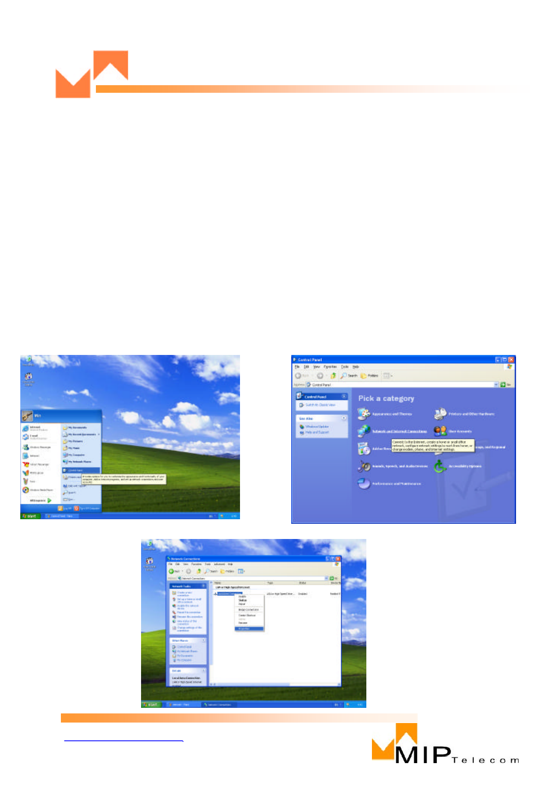
1. Choose Start, Control Panel. ( Figure 3.3.1)
2. Choose Network and Internet Connections (Figure 3.3.2)
3. Choose Network Connections (Figure 3.3.3)
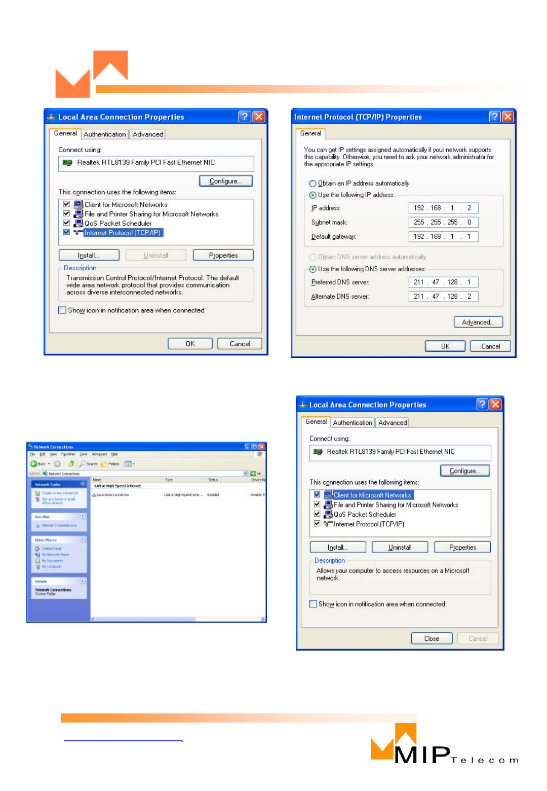
4. Click Local Area Connection(Figure 3.3.4)
5. Click property
Select Internet protocol (TCP/IP) under General Tap. (Figure 3.3.5)
6. Click Property
Select “Use the following IP Address”. Then type in below. (Figure 3.3.6)
IP Address: 192.168.1.2
Subnet Mask: 255.255.255.0
Default Gateway: 192.168.1.1
7. Click OK ( Figure 3.3.7)
Go to Combox™Configuration
<Figure 3.3.1> <Figure 3.3.2>
<Figure 3.3.3>
WWW.MIPTEL.COM
MIP0201000B
9
<Figure 3.3.4> <Figure 3.3.5>
<Figure 3.3.6>
<Figure 3.3.7>

WWW.MIPTEL.COM
MIP0201000B
10
Combox™Configuration
You can configure your MIP Telecom Combox™by using the web configuration page.
Follow these steps:
Step 1 Make sure that the PC and the MIP Telecom Combox™are already networked
and visible to one another.
Step 2 Open your web browser.
Step 3 Enter the URL of your configuration page.
For example, the configuration page for a MIP Telecom Combox™ with the
IP address 192.168.1.1 is:
http://192.168.1.1
WWW.MIPTEL.COM
MIP0201000B
11
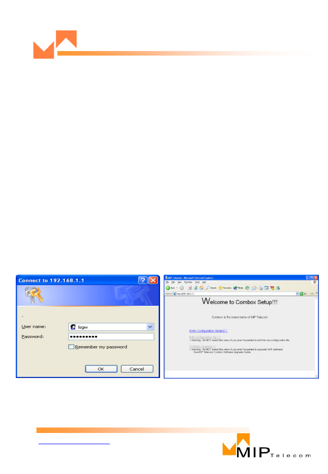
<Figure 4.1> <Figure 4.2>
Step 4 Select the values for the items that you want to configure.
1. Key in ID:lsgw and Password:lsgw11111 (Figure 4.1)
2. Click Enter Configuration on Configuration Wizard ( Figure 4.2)
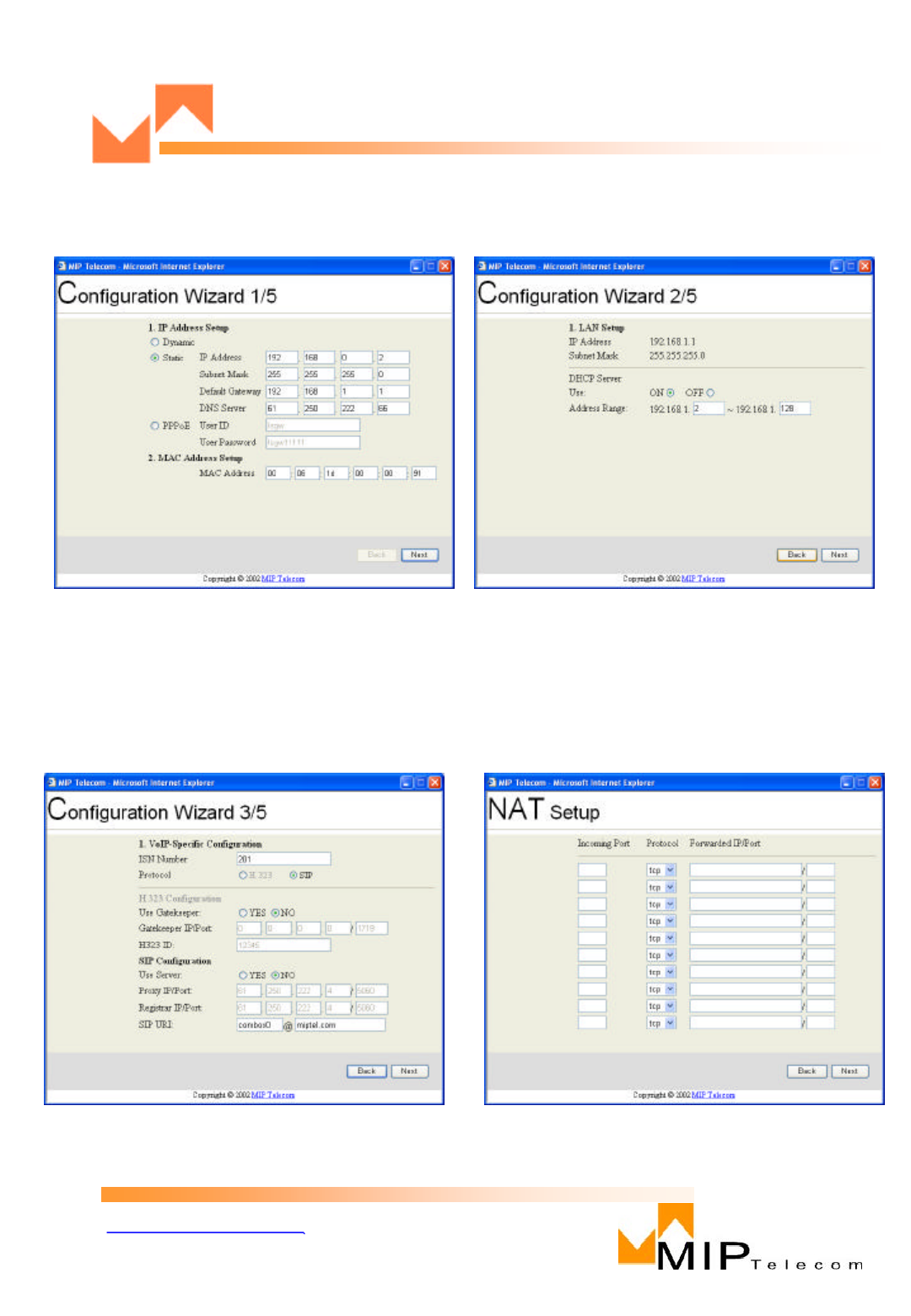
3. Provide required info based on your Internet Connection on Configuration
Wizard 1/5. Click Next ( Figure 4.3)
4. Provide required info on Configuration Wizard 2/5. Click Next ( Figure 4.4)
5. Enter “ISN Number”and Protocol specification provided by your ITSP on
Configuration Wizard 3/5. If you make an Point-to-point call without an ITSP,
Select No on H.323/SIP Configuration. (Figure 4.5)
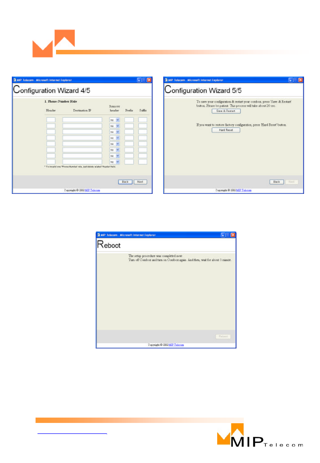
6. Numbering rule is available if you don’t want to go thru gatekeeper and SIP server.
Click next ( Figure 4.6)
7. NAT Setup function is an option. Please contact application service providers to get
more info. Otherwise, click next. ( Figure 4.7)
8. Click “Save & Restart”on Configuration Wizard 5/5. Click Next( Figure 4.8)
9. Reboot. ( Figure 4.9)
Step 5 Click Reboot to save your changes.
WWW.MIPTEL.COM
MIP0201000B
12
<Figure 4.3> <Figure 4.4>
<Figure 4.5> <Figure 4.6>
WWW.MIPTEL.COM
MIP0201000B
13
<Figure 4.7> <Figure 4.8>
<Figure 4.9>

WWW.MIPTEL.COM
MIP0201000B
14
Making a Call
Note :The dial plan described in these instructions is the default plan. You
can configure your MIP Telecom Combox™to use a different plan.
Follow these steps to make a call:
Step 1 Lift the telephone handset.
Step 2 Dial as you normally do.
Tips If you want to send the dial string out immediately, without waiting for the 2-to 4-
second timeout, press # after the last digit.
If the called party is available, you will hear ringing.
Step 3 When the called party answers, speak normally.
Step 4 Hang up when finished.
You can cancel or discontinue your call at any time by hanging up the handset.

WWW.MIPTEL.COM
MIP0201000B
15
Limited Warranty
MIP Telecom, Inc. (“MIP”) warrants that its products will be free from defects in
material or workmanship for a period ofone years from the date of purchase, or
if proof of purchase is not provided, one years from date of shipment.
MIP MAKES NO OTHER WARRANTY, EXPRESSED OR IMPLIED, AND
ALL IMPLIED WARRANTIES OF MERCHANTABILITY AND FITNESS
FOR A PARTICULAR PURPOSE ARE HEREBYDISCLAIMED.
This warranty does not apply to any products which have been damaged by light
ning storms, water, or power surges or which have been neglected, altered,
abused, used for a purpose other than the one for which they were manufactured,
repaired by the customer or any party without MIP’s written authorization, or use
d in any manner inconsistent with MIP’s instructions.
MIP’s entire obligation under this warranty shall be limited (at MIP’s option) to
repair or replacement of any products whichprove to be defective within the war
ranty period, or, at MIP’soption, issuance of a refund of the purchase price.
Defective products must be returned by Customer to MIP’s factorytransportation
prepaid.
MIP WILL NOT BE LIABLE FOR CONSEQUENTIAL DAMAGES
AND UNDER NO CIRCUMSTANCES WILL ITS LIABILITY EXCEED THE
PURCHASE PRICE FOR DEFECTIVE PRODUCTS.
Technical Support
MIP Telecom, Inc, Systems has an excellent staff of technical support
personnel available to help you get the most out of your MIP product. If you ha
ve any questions about the operation of this unit, or experience difficulty
during installation you cancontact Tech Support via the following:
Phone:
(82)2-557-3399
Internet: http://www.miptel.com
Please have your product information available, including model and serial
number.

WWW.MIPTEL.COM
MIP0201000B
16
FCC Declaration
NOTE: This equipment has been tested and found to comply withthe limits for
a Class A digital device, pursuant to Part 15 of the FCC Rules. These limits are
designed to provide reasonable protection against harmful interference when the
equipment is operated in a commercial environment. This equipment generates,
uses and can radiate radio frequency energy, and if not installedand used in
accordance with the instructions, may cause harmful interference to radio
communications. Operation of this equipment in a residential area is likely to
cause harmful interference in whichcase the user will be required to correct the
interference at his own expense.
Warning: Changes or modifications to this unit not expressly approved by the
party responsible for compliance could void the user’s authority to operate the
equipment.