MIPAC CVM-AP MODEM FOR CONNECTING TO WIRELESS SENSOR NETWORK User Manual Appendix F CVM AP R02 USERMAN
MIPAC Pty Ltd MODEM FOR CONNECTING TO WIRELESS SENSOR NETWORK Appendix F CVM AP R02 USERMAN
UserManual.wiki
>
MIPAC
>
CVM AP User Manual
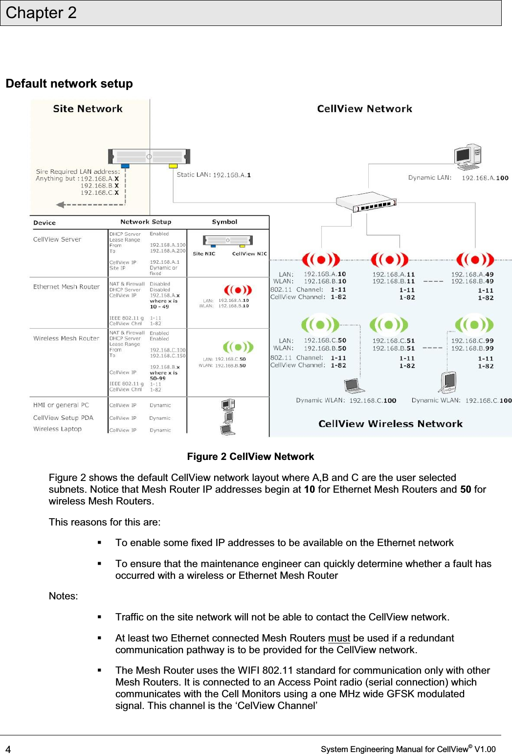
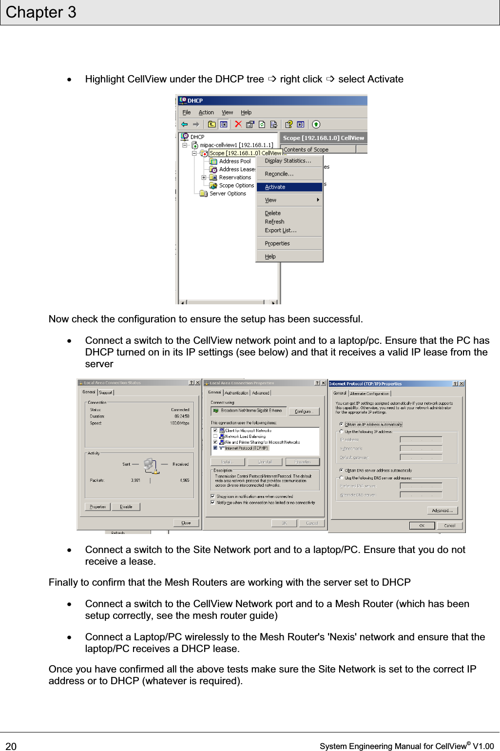
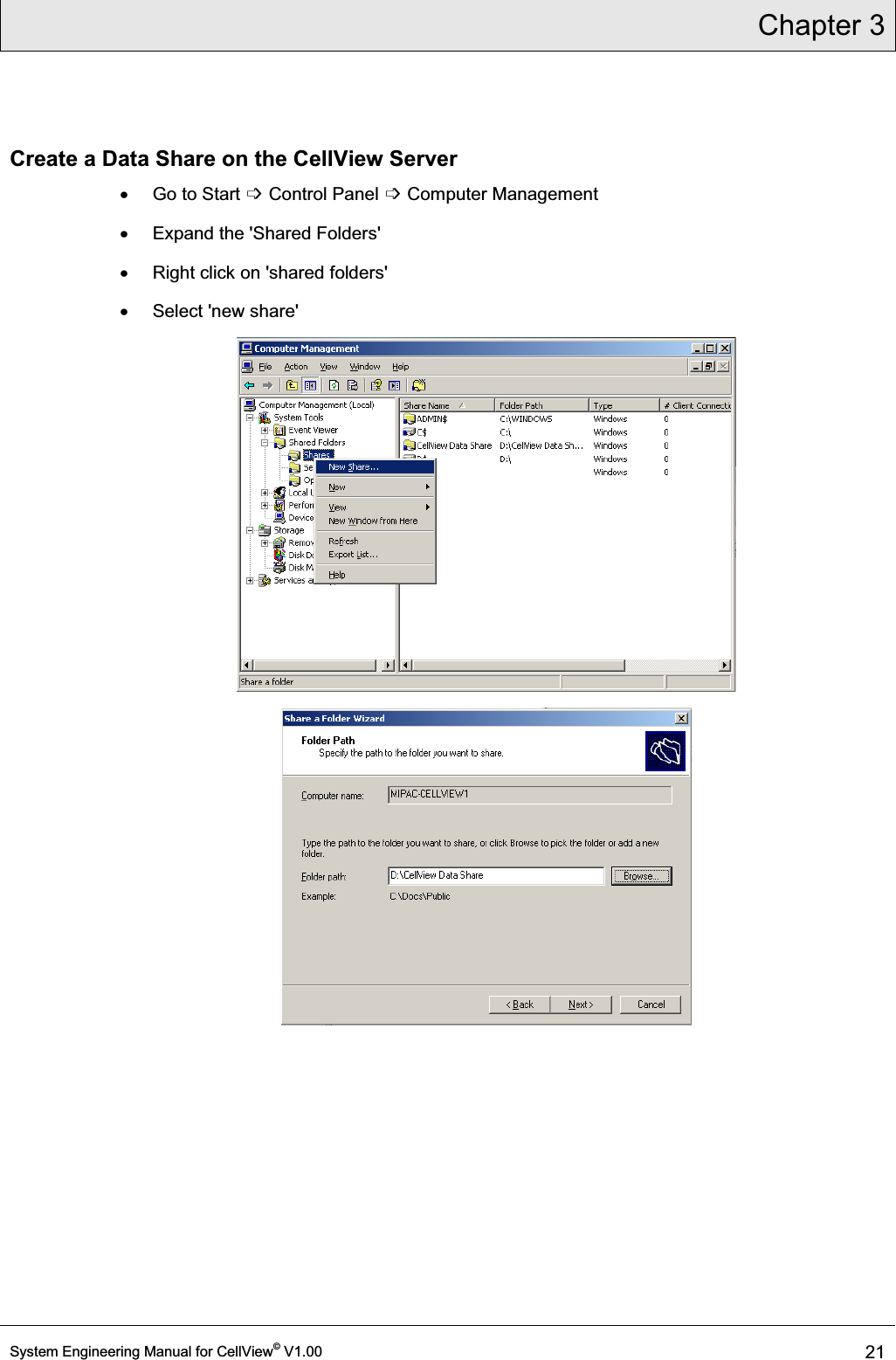
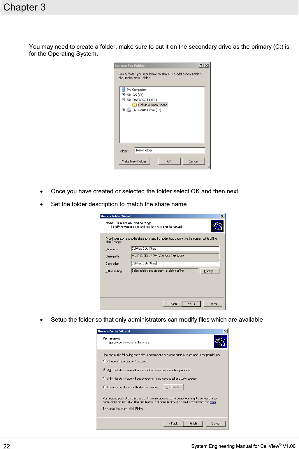
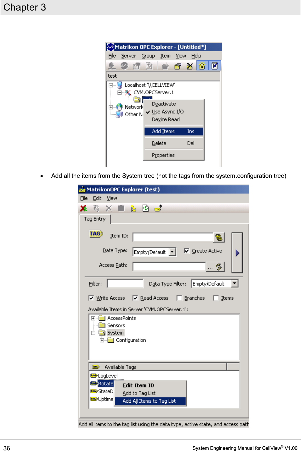
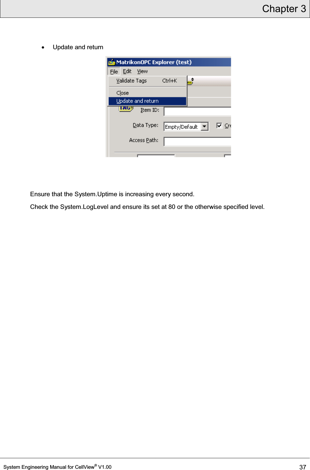
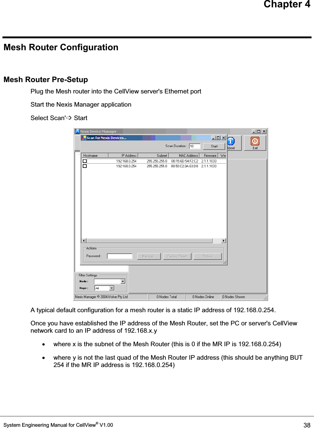
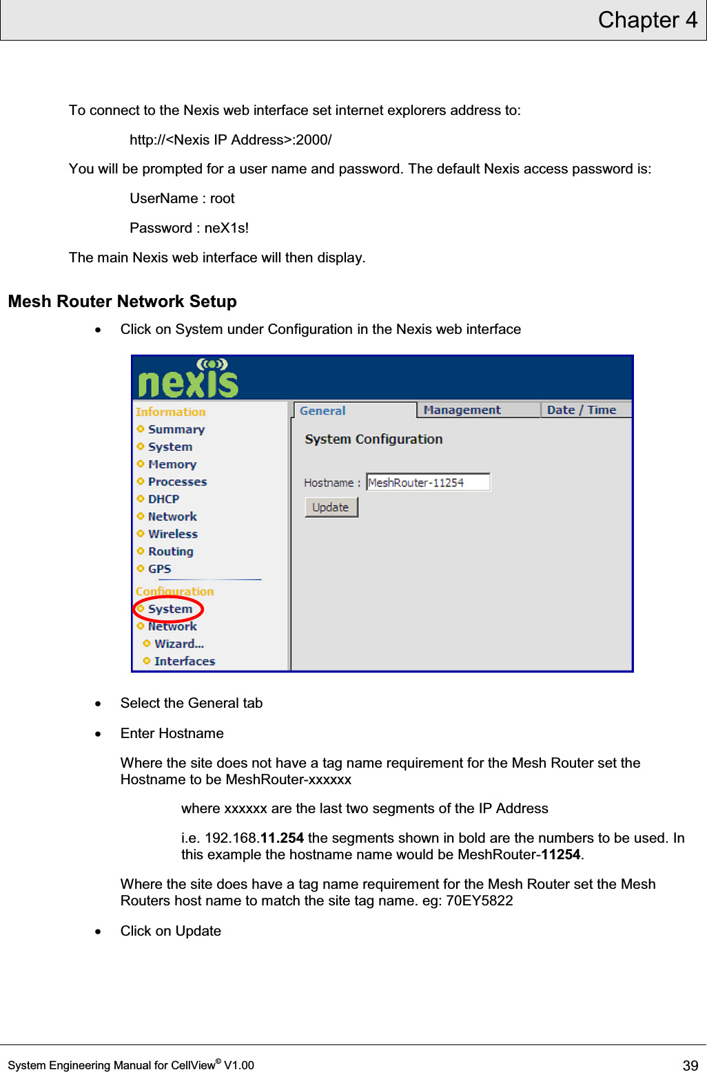
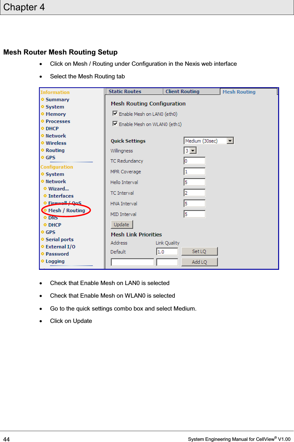
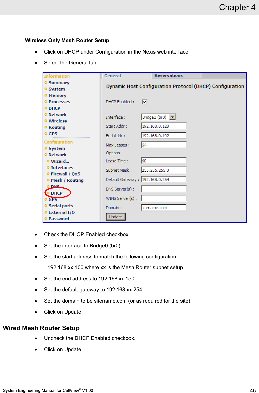
USERS MANUAL
Navigation menu
Upload a User Manual
Namespaces
Wiki Guide
HTML
PDF
Info
Views
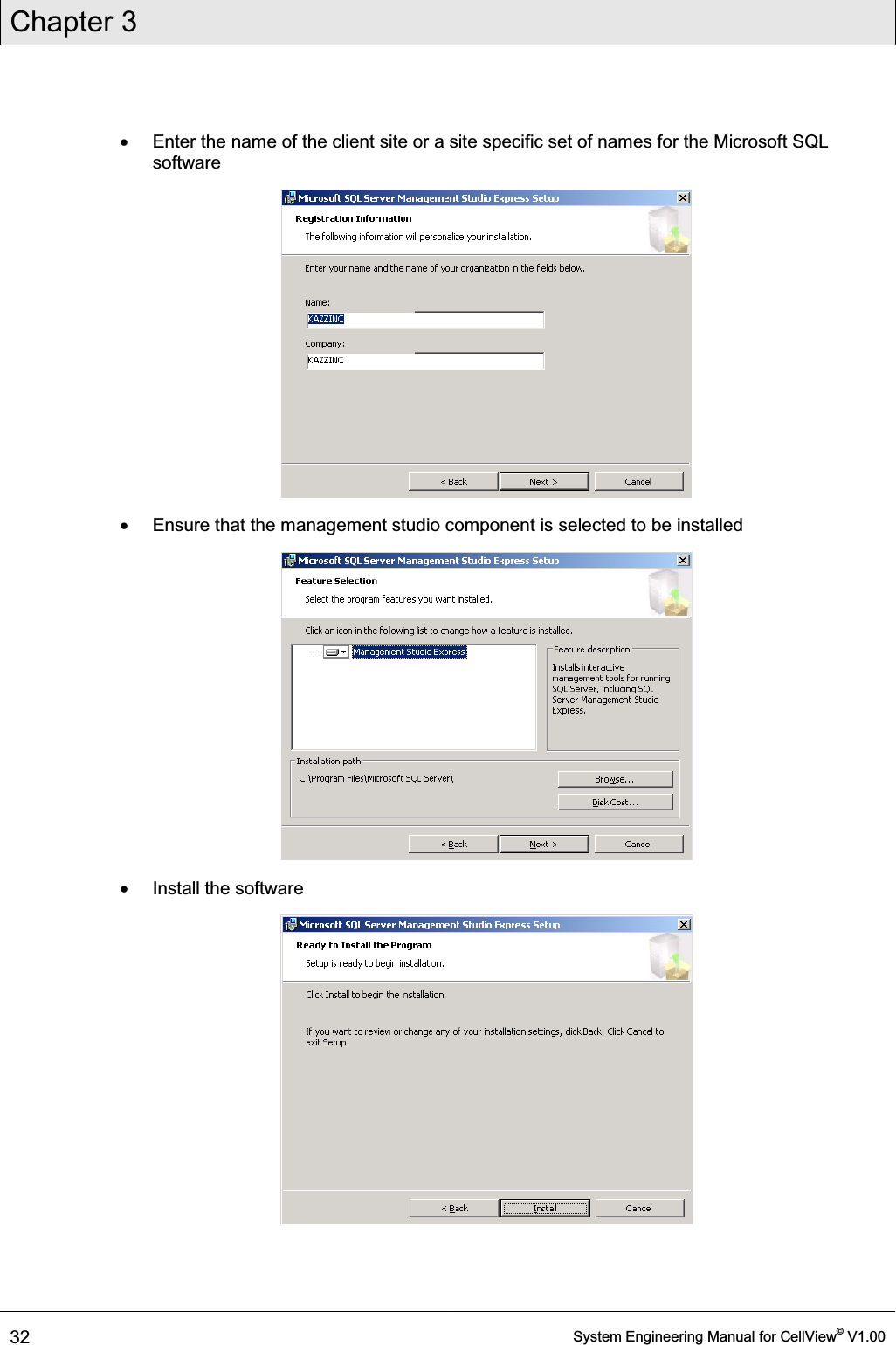
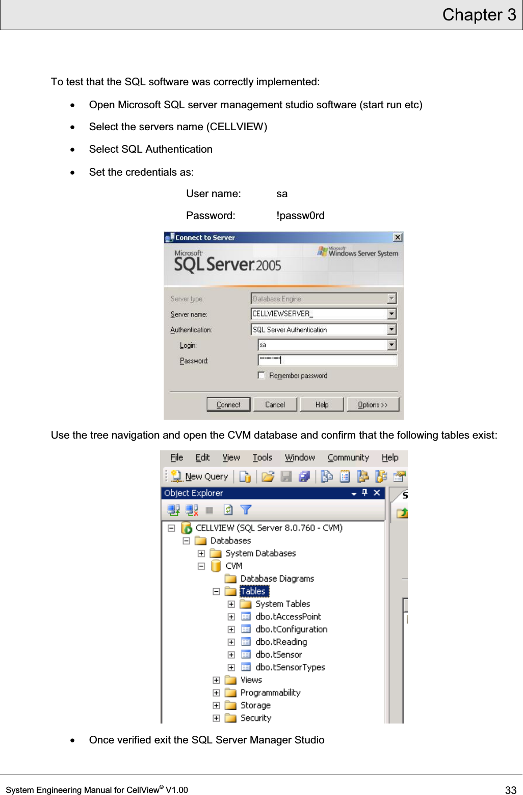
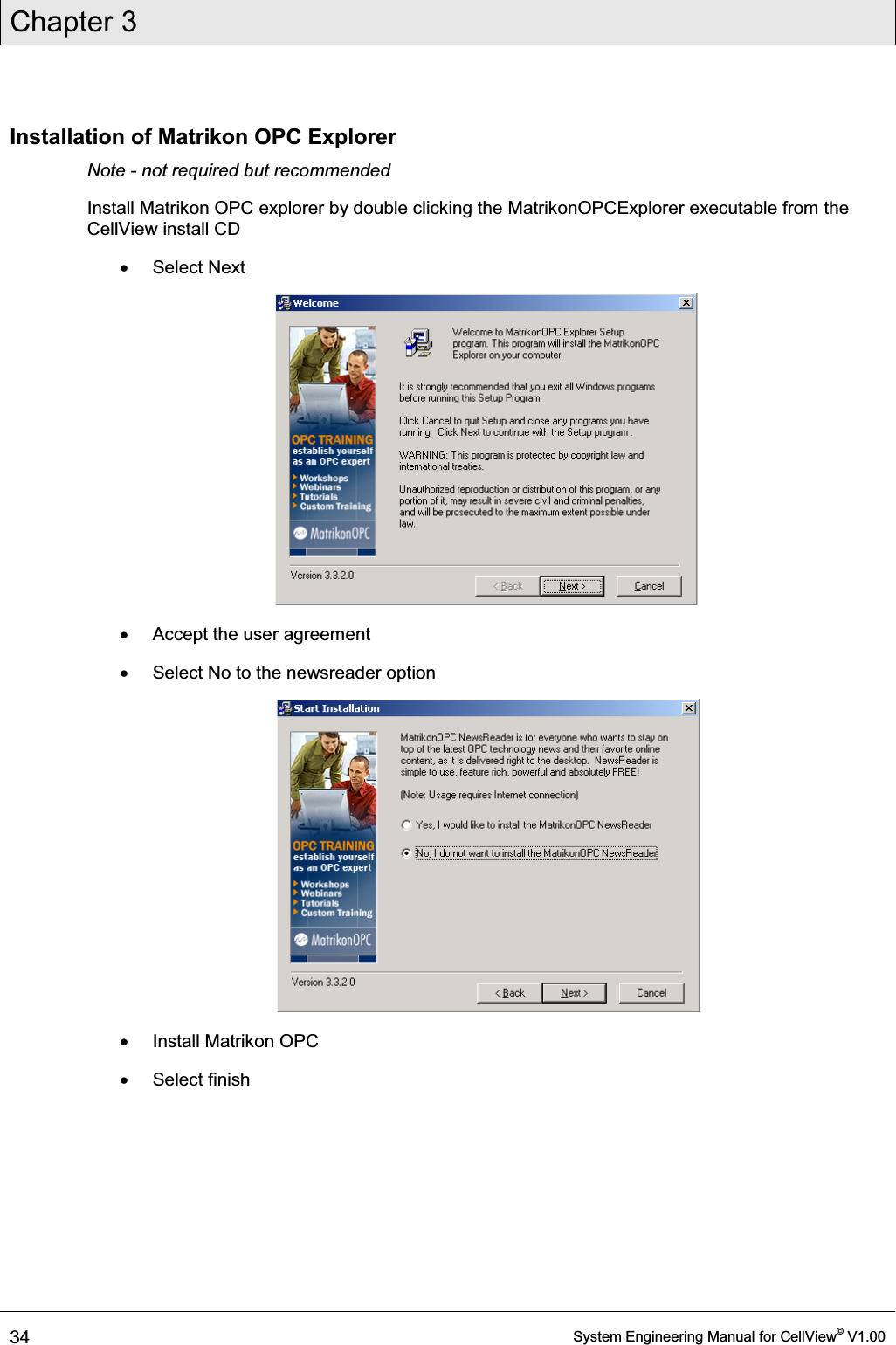
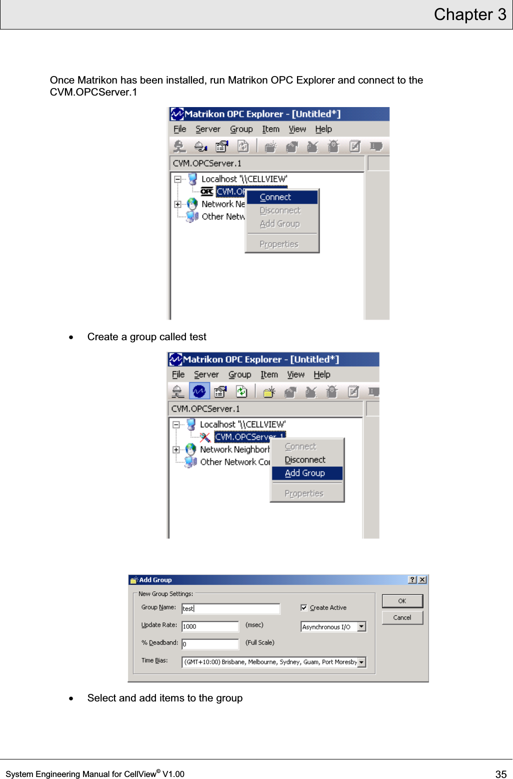
User Manual
Discussion / Help
Navigation