MOBASE ELECTRONICS SYECLWPC1707 Wireless Charging System User Manual
SEOYON ELECTRONICS CO., LTD. Wireless Charging System
User Manual
U S E R M A N U A L
Page
1/11
Established By
W.P.C SYSTEM
Spec No.
Seoyon Electronics
I N D E X
1. PURPOSE
2. SCOPE
3. ABBREVIATIONS AND DEFINITIONS
4. SYSTEM OVERVIEW
-
RELEASED
ALL
2017.05.26
W.C NO
Rev.NO
DESCRIPTION OF CHANGED
CHANGE PAGE
REV. DATE
REV. BY
REV. DATE
2017.05.26
SORT
PREPARED
CHECKED
APPROVED
A
P
P
R
O
V
A
L
WON CHUL
NO
HO NAM
KIM
GYEONG HEUM
CHOI
(PLM MANAGEMENT
SYSTEM)
DSF-4-02-01A-1 SEOYON ELECTRONICS A4(210x297)
U S E R M A N U A L
SPEC NO
(SHT/SHTS) 2/11
Document Change History
Date
Ver.
Editor
Chap.
Description
CR#

U S E R M A N U A L
SPEC NO
(SHT/SHTS) 3/11
Contents list page
1. PURPOSE ............................................................................................................................................... 3
2. SCOPE ................................................................................................................................................ 4
3. ABBREVIATIONS AND DEFINITIONS .......................................................................................... 4
4. SYSTEM OVERVIEW ........................................................................................................................ 6
4.1. SYSTEM DESCRIPTION ........................................................................................................................................6
4.2. OPERATION PRINCIPLE .......................................................................................................................................6
4.3. ROLE AND CHARATERISTICS OF W.P.C PING ................................................................................................8
4.4. W.P.C COMMUNICATION AND CHARGING CHARACTERISTICS ................................................................9
4.5. PACKET LIST OF W.P.C CONTROLLER ..............................................................................................................9
4.6. W.P.C FLOW CHART ......................................................................................................................................... 10
4.7. HARDWARE CONFIGURATION ....................................................................................................................... 10
4.8. SYSTEM CONFIGURATION .............................................................................................................................. 11
4.9. W.P.C OPERATION CONDITION ..................................................................................................................... 11
4.9.1. W.P.C OPERATING VOLTAGE .......................................................................................................................... 11
4.9.2. W.P.C INPUT/OUTPUT SPECIFICATIONS ...................................................................................................... 12
4.9.2.1.UNIT Input/Output Interface ........................................................................................................................................................... 12
1. PURPOSE
This specification specifies general functional requirements, quality requirements and
constraints applicable to the wireless charging system. If there is a difference between this
specification and the drawings, the drawings take precedence.
U S E R M A N U A L
SPEC NO
(SHT/SHTS) 4/11
2. SCOPE
This specification specifies general functional requirements, quality requirements and
constraints applicable to the wireless charging system. If there is a difference between this
specification and the drawings, the drawings take precedence.
3. ABBREVIATIONS AND DEFINITIONS
Item, abbreviation,
acronym
Description
WPC
Wireless Power Charger
Active Area
An interface surface portion through which magnetic flux penetrates
sufficiently when the base station provides power to the mobile device
Power Transmitter
Wireless power transmission system Subsystem of base station that
generates inductive power in Active Area and controls power transmission
to RX
Base Station
Devices that transmit power wirelessly
Digital Ping
Application of Power Signal for RX Detection and Device Identification
Free Positioning
Place the mobile device on the interface surface of the base station.
The user does not need to align the active area of the mobile device
with the active area of the base station.
Guided Positioning
One way to locate a mobile device on the interface surface of the base
station is to provide feedback for the user to align the active area of
the mobile device to the active area of the base station
Interface Surface
Base station and mobile device Connected surface
Mobile Device
Devices that can consume inductive power in active area in wireless power
transmission system
Packet
Data structure that RX uses to communicate messages to TX
Power Receiver
Wireless Power Transmission System Subsystem of Mobile Device that
acquires inductive power in Active Area and controls the validity of its
output power
Power Signal
Vibrating flux surrounded by primary cell and secondary coil
Power Transfer
Contract
A set of boundary conditions with parameters having characteristics for
power transmission from TX to RX

U S E R M A N U A L
SPEC NO
(SHT/SHTS) 5/11
Primary Cell
A single Primary Cell or Primary Cell used to provide high magnetic flux
through the Active Area
Secondary Coil
Parts of RX that switch from magnetic flux to electromotive force
Table 1 : ABBREVIATIONS
U S E R M A N U A L
SPEC NO
(SHT/SHTS) 6/11
4. SYSTEM OVERVIEW
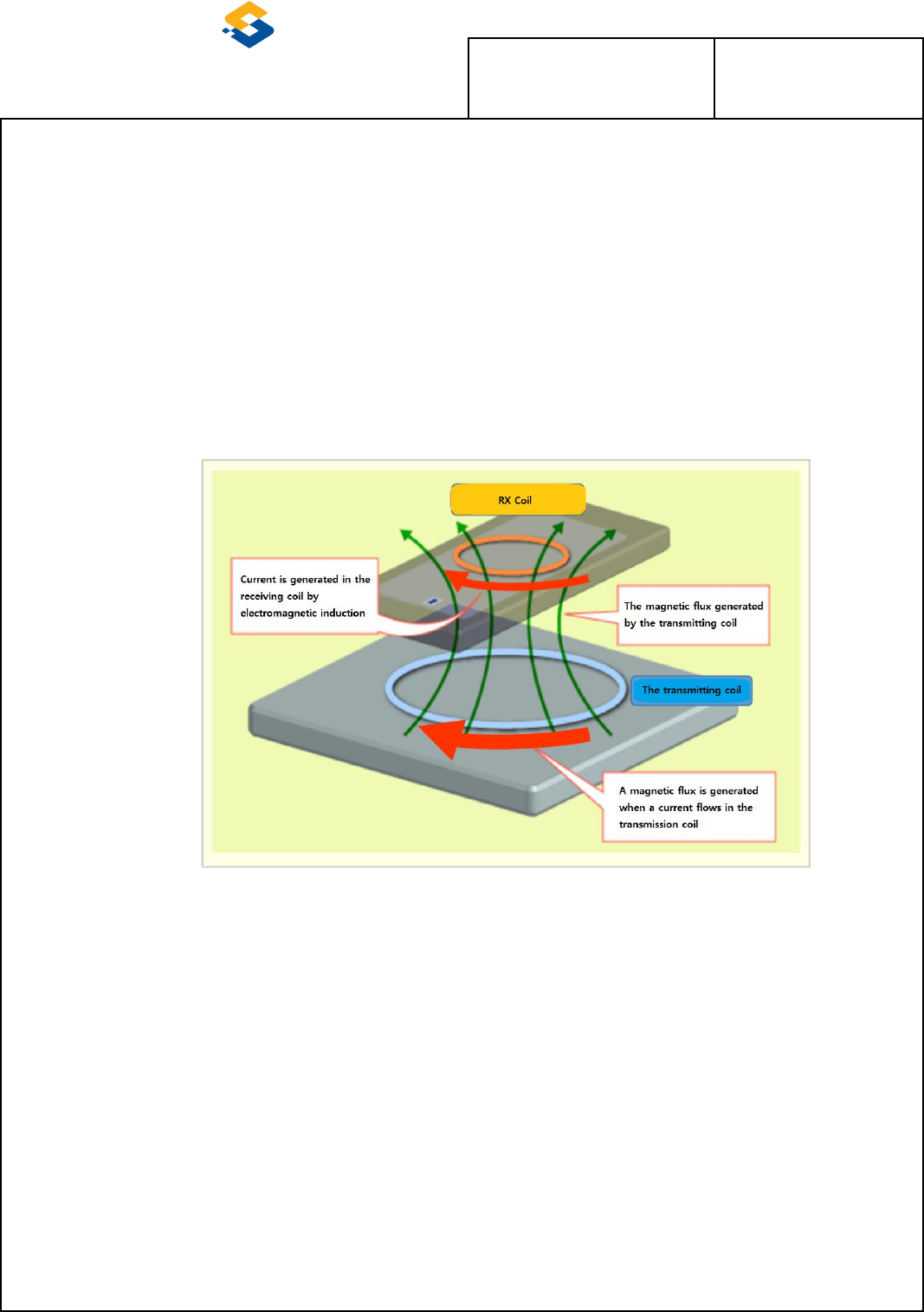
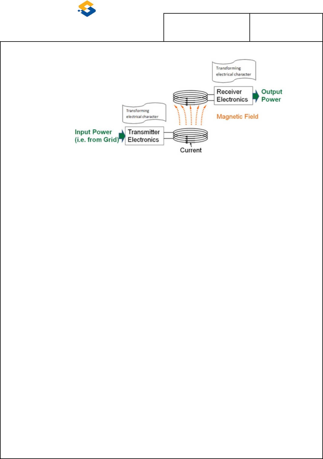
4.1. SYSTEM DESCRIPTION
A wireless charger (WPC) installed in a vehicle is a system that transmits power to a mobile
phone or a power receiver by power transmission by magnetic induction of a WPC coil and a cell
phone coil without a USB connection.
Picture 1 :OPERATION PRINCIPLE
4.2. OPERATION PRINCIPLE
WPC transmits power by magnetic induction to the overlapping area of the coil inner diameter of WPC and
the coil inner diameter of WPC with LC resonance (111KHZ).
U S E R M A N U A L
SPEC NO
(SHT/SHTS) 7/11
Picture 2 : POWER FLOW
U S E R M A N U A L
SPEC NO
(SHT/SHTS) 8/11
4.3. ROLE AND CHARATERISTICS OF W.P.C PING
- Analog Ping : Meter reading on wireless charge controller
- Digital Ping : Verify that the meter reading is a wireless charger WPC receiver
Packet
Input
Sequence
Packet
Purpose
Division
1
Signal Strength
Receiver Type
Digital Ping
2
Identification
Information such as the
receiver manufacturer
3
Configuration
Receiver internal
information
4
End Power Transfer
Stop power transmission
Digital Ping
Table 2 : Digital Ping Packe
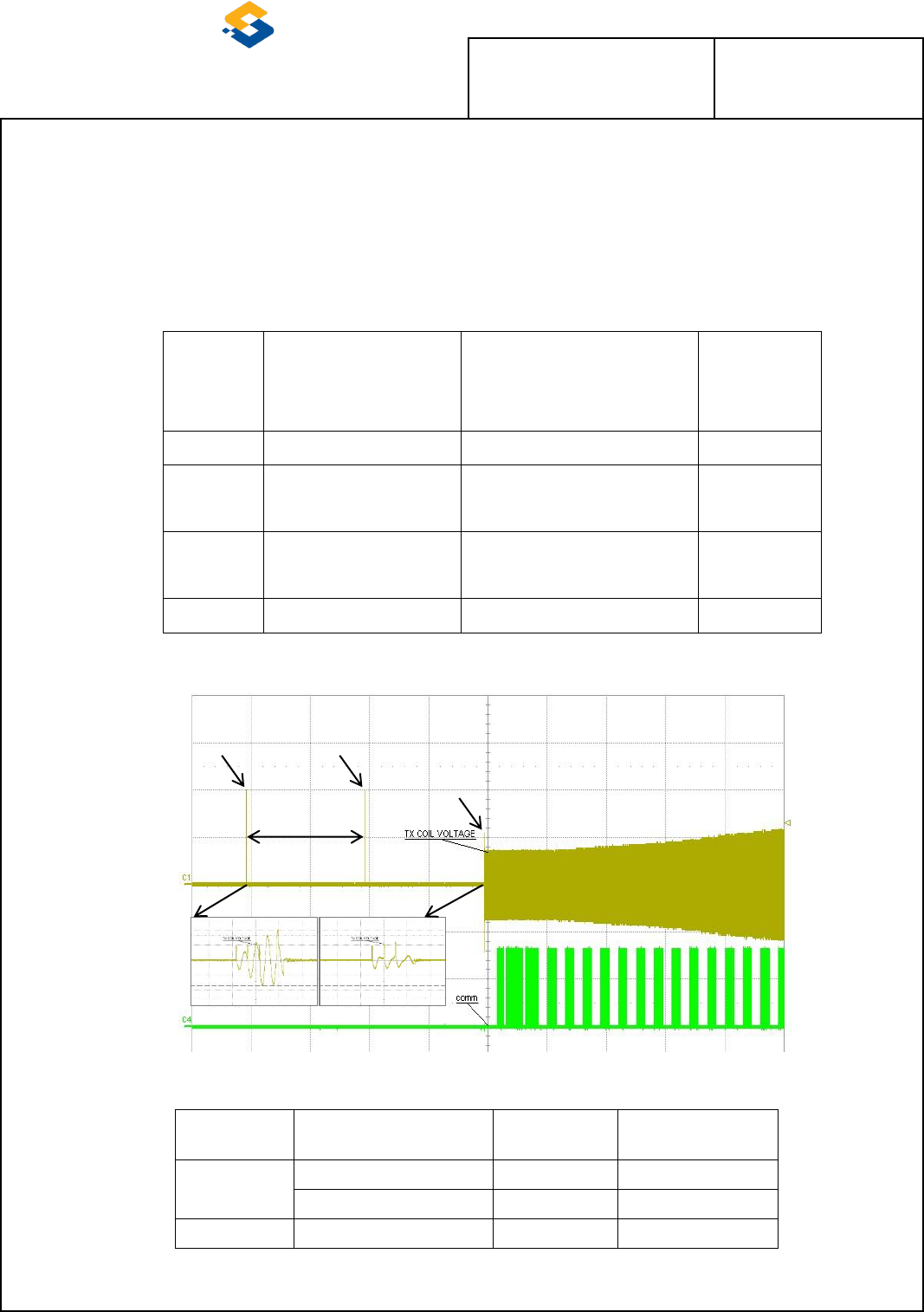
Picture 3 : Receiver Recognition (Ping) Phase and Power Transfer Phase
Ping
Division
Voltage
Timing
Frequency
Analog
SIDE : 3.5V±0.5V
500ms
111kHz±5kHz
Center : 3.0V±0.5V
500ms
111kHz±5kHz
Digital
-
64ms
111kHz±5kHz
Table 3 : Ping Specification
500msec
Within
Analog Ping
(Pad No object)
above)
Analog Ping-Pad After detection of
upper object Digital Ping and receiver
information recognition
U S E R M A N U A L
SPEC NO
(SHT/SHTS) 9/11
4.4. W.P.C COMMUNICATION AND CHARGING CHARACTERISTICS
Wireless Charging Transmits messages with uni-directional in-band (ASK) communication using a
specific frequency between the transmit coil and the receive coil.
The wireless charger transmit coil transmits the power of the MAX15W and the operating
frequency is 111KHZ.
Confidential
Picture 4 : Wireless charging controller communication method
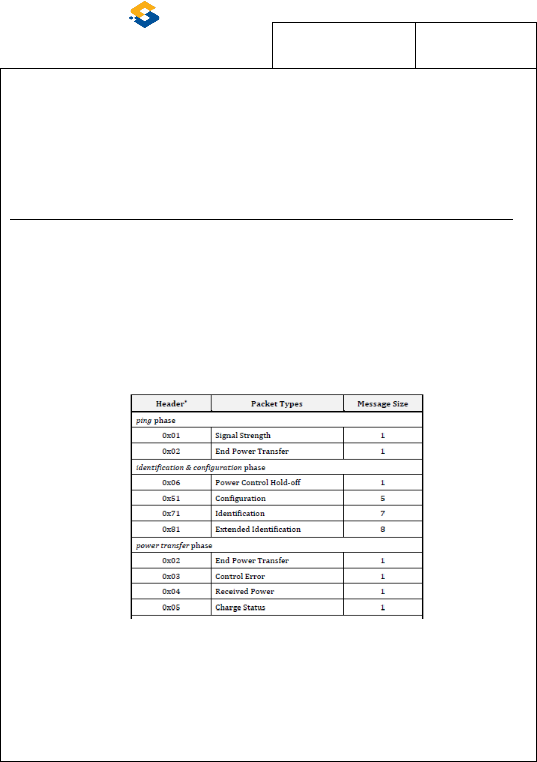
4.5. PACKET LIST OF W.P.C CONTROLLER
Table 4 : W.P.C Packet List
U S E R M A N U A L
SPEC NO
(SHT/SHTS) 10/11
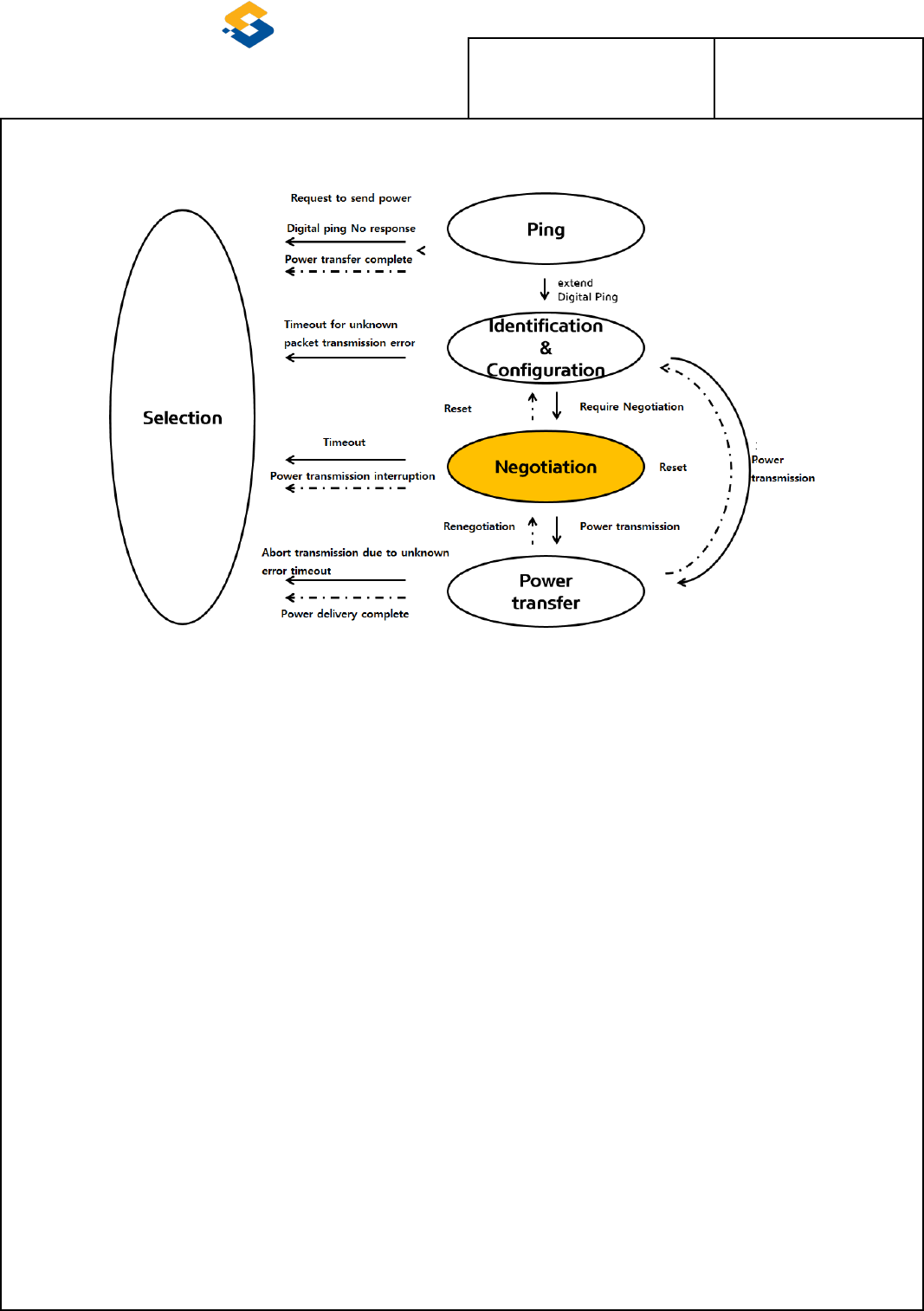
4.6. W.P.C FLOW CHART
Picture 5 : W.P.C Flow Chart
4.7. HARDWARE CONFIGURATION
The hardware configuration consists of Conrtoll, wireless charging, and wireless charging
antenna coils.
- CONRTOLL CIRCUIT
1. Control of wireless charger operation
2. INDICATOR operation controll
3. CAN communication controll
- W.P.C CIRCUIT
1. Wireless Charging Antenna Coil transfers the power received from BATTEY
2. Check the unidirectional Inventory (ASK) data received from the mobile phone to
control the transmission power
3. Control the amount of transmission power through voltage variation
4. Control of rechargeable coil selection function among 3 coils
- Wireless Charging Antenna Coil
1. Delivered power from wireless charging circuit to mobile phone
U S E R M A N U A L
SPEC NO
(SHT/SHTS) 11/11
4.8. SYSTEM CONFIGURATION
Confidential
Picture 6 : WPC BLOCK DIAGRAM
4.9. W.P.C OPERATION CONDITION
4.9.1. W.P.C OPERATING VOLTAGE
OPERATION
Signal
Value
Protection
Chattering
Time
Re
marks
LOW
HIGH
Under
Over
Detect
Release
Detect
Release
CAN
B+
6.8V
7V
7.0V
7.5V
18V
17.5V
30ms
WPC
B+
8.5V
9V
9.0V
9.5V
16.5V
16.0V
30ms
A_ACC
7.1V
7.8V
-
-
-
-
30ms
LF_Searching
3.0V
5.6V
-
-
-
-
10ms
LED_AMBER
8.5V
9V
-
-
-
-
-
500ms
LED_GREEN
8.5V
9V
-
-
-
-
-
500ms
Table 5 : W.P.C OPERATING VOLTAGE
U S E R M A N U A L
SPEC NO
(SHT/SHTS) 12/11
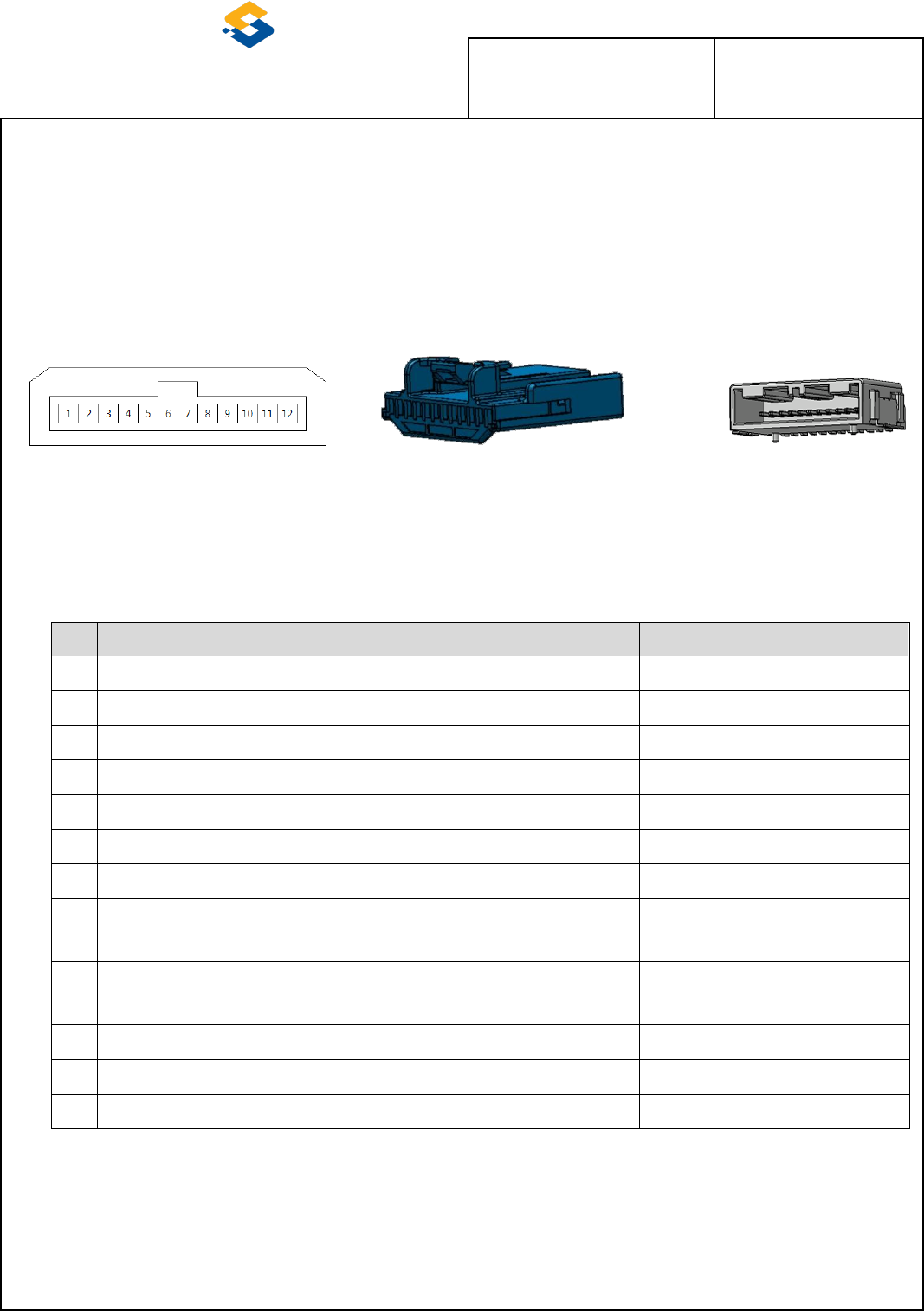
4.9.2. W.P.C INPUT/OUTPUT SPECIFICATIONS
- UNIT CONNECTOR : KET MG645877
- UNIT WIRING CONNECTOR : KET MG655823
Picture 7 : UNIT CONNECTOR (12PIN)
4.9.2.1.UNIT Input/Output Interface
Pin
Designation
PIN Description
Diagnosis
Short circuit proof
1
B+
BATTERY Voltage Input
N/A
2
A_ACC
ACC Voltage Input
N/A
3
N.C.
NO.CONNECT
N/A
4
L_LFSearchingOn_IN
SMK Searching State Input
Pull-up resistor/diode
5
B-CAN_HI
LS-CAN High Level Signal
IC self protection
6
B-CAN_LO
LS-CAN Low Level Signal
IC self protection
7
N.C.
NO.CONNECT
N/A
8
P_LED_GREEN
Charging State Output
Current limit circuit applied
(PWM operation)
9
P_LED_AMBER
Charging State Output
Current limit circuit applied
(PWM operation)
10
GND_ECU
Ground CONNECT INDICATOR
N/A
11
N.C.
NO.CONNECT
N/A
12
GND_POWER
Ground
N/A
Table 6 : UNIT Input / Output Inerface
<UNIT >CONNECTER
<WIRING CONNECTOR>
<PIN MAP>

U S E R M A N U A L
SPEC NO
(SHT/SHTS) 13/11
FCC
This device complies with part 15 of the FCC Rules. Operation is subject to the following two conditions:
(1) This device may not cause harmful interference, and (2) this device must accept any interference
received, including interference that may cause undesired operation.
This equipment has been tested and found to comply with the limits for a digital device, pursuant to part
15 of the FCC Rules. These limits are designed to provide reasonable protection against harmful
interference in a residential installation. This equipment generates, uses and can radiate radio
frequency energy and, if not installed and used in accordance with the instructions, may cause harmful
interference to radio communications. However, there is no guarantee that interference will not occur in
a particular installation. If this equipment does cause harmful interference to radio or television
reception, which can be determined by turning the equipment off and on, the user is encouraged to try to
correct the interference by one or more of the following measures:
Reorient or relocate the receiving antenna.
Increase the separation between the equipment and receiver.
Connect the equipment into an outlet on a circuit different from that to which the receiver is connected.
Consult the dealer or an experienced radio/TV technician for help.
Changes or modifications not expressly approved by the party responsible for compliance could void the
user's authority to operate the equipment.
This device complies with RF exposure requirement.

U S E R M A N U A L
SPEC NO
(SHT/SHTS) 14/11
IC
This device complies with Industry Canada license-exempt RSS standard(s).
Operation is subject to the following two conditions:
(1) this device may not cause interference, and
(2) this device must accept any interference, including interference that may cause undesired
operation of the device.
Le present appareil est conforme aux CNR d'Industrie Canada applicables aux appareils radio exempts
de licence. L'exploitation est autorisee aux deux conditions suivantes :
(1) l'appareil ne doit pas produire de brouillage, et.
(2) l'utilisateur de l'appareil doit accepter tout brouillage radio electrique subi, meme si le
brouillage est susceptible d'en compromettre le fonctionnement.
This device complies with RF exposure requirement.
Cet appareil est conforme à l'exigence d'exposition RF.