MOBILE CREATE SL8090 Wireless Module User Manual
Mobile Create Co., Ltd. Wireless Module
User Manual
Rev. 1.0
–
2015
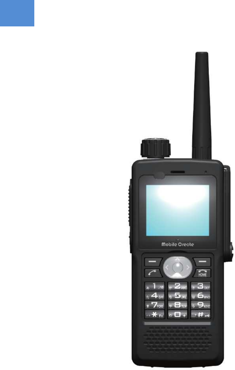
MPT-H1
Mobile Create Co., Ltd.
INSTRUCTION MANUAL
- 2 -
PLEASE OBSERVE FULLY
Be sure to observe the following precautions fully for the safe and proper use of this product:
■ Explanations of safety alert signs
This sign indicates a hazardous situation which could significantly result in serious injury
or death.
This sign indicates a hazardous situation which could result in serious injury or death.
This sign indicates a hazardous situation which could result in physical or property
damage.
■ Explanations of symbols
This symbol indicates precautions which need to be fully observed.
This symbol indicates notes which are requested to be considered.
■
Do not operate this product while driving a car. Before operating this product, a driver shall stop the car in a safe
place.
■
Do not install or operate this product in airplanes and hospitals, or it could affect electronic and medical devices.
■
Do not install or operate this product in places where inflammable gas is generated, or it could cause an ignition
accident.
■
Cardiac pacemaker users shall not use this product, because it could affect pacemakers, causing an accident due
to the malfunction of such devices.
■
Use this product away from automatic control equipment such as automatic door and fire alarm systems, or the
radio waves generated by this product could affect such equipment, causing an accident due to malfunction.
■
Do not install or operate this product in a place which may obstruct the operator’s front vision or interfere with the
operation, or it could cause an injury, an accident, or a failure.
■
Pay attention to the speaker volume while driving so that the sound outside the car can be heard. Failure to do so
could cause an injury or accident.
■
Do not disassemble or modify this product, or it could cause an injury, an accident, or a failure.
■
Do not install or operate this product in places which are subject to direct sunlight, or it could cause resin deformation
or discoloration, or a failure.
■
Do not give an impact to or throw this product, or it could cause a failure.
■
Do not connect this product to any devices other than the specified ones, or it could cause a failure.
■
Keep this product away from magnetic cards such as cash cards, or the data on them may be lost.
■
Do not use thinner or alcohol when cleaning this product, or it could cause resin deformation or discoloration, or a
failure.
Safety Precautions
DANGER
WARNING
CAUTION
WARNING
CAUTION

- 3 -
Matters prohibited when handling the battery pack
■
Do not disassemble or modify the battery pack, because it incorporates a safety mechanism and protective device
for preventing danger. Damaging such mechanism or device could cause heat or smoke generation from or
explosion or ignition of the battery pack.
■
Do not connect the positive electrode to the negative electrode using metal such as wire. Also do not carry or store
this product with metal goods such as necklaces or hairpins. Failure to do so could short-circuit the battery pack and
generate an excessive amount of electricity, causing heat or smoke generation, explosion or ignition of the battery
pack, as well as heat generation of metal goods such as necklaces and hairpins.
■
Do not put the battery pack in open flame or heat it, or it could melt insulators, damage the gas blowdown valve or
the safety mechanism, or ignite the electrolyte solution, causing heat or smoke generation, explosion, or ignition.
■
Do not use or install the battery pack in hot places (80°C or higher) such as by open flame or a heater. If the resin
separator is damaged by the heat, the battery pack may be short-circuited internally, causing heat or smoke
generation, explosion or ignition.
■
Do not soak the battery pack in or make it wet with water or seawater. The protective device incorporated in the
battery pack could cause heat or smoke generation, explosion, or ignition of the battery pack.
■
Do not recharge the battery pack by open flame or in the hot sun. If the battery pack becomes hot, the protective
device for preventing danger is activated to stop recharging or the protective device may break to recharge the
battery pack at an abnormal current or voltage, causing heat or smoke generation, explosion, or ignition due to
abnormal chemical reaction inside the battery pack.
■
Recharging the battery pack under any condition other than the specified ones (such as at higher temperature,
voltage, or current than the specified ones, or with a modified recharging cradle). In addition, the battery pack is
recharged with abnormal current, leading to abnormal chemical reaction inside it which could cause heat or smoke
generation, explosion, or ignition.
Note: Working temperature and humidity ranges of the recharging cradle: 0 to 40°C / 45 to 85%RH
■
Do not drive a nail into, hammer, or step upon the battery pack, or it may be disrupted or deformed to be short-
circuited internally, causing heat or smoke generation, explosion, or ignition.
■
Do not give a strong impact to or throw the battery pack, or it could cause liquid leakage, heat or smoke generation,
explosion, or ignition. In addition, if the protective device incorporated in the battery pack is broken, the battery pack
may be recharged with abnormal current or voltage, leading to abnormal chemical reaction inside the battery pack
which could cause heat or smoke generation, explosion, or ignition.
■
Do not use a battery pack with an external surface that is damaged or an external appearance that is significantly
changed, or it could cause heat or smoke generation, explosion, or ignition.
■
Do not solder the battery pack directly, or the insulator may melt from the heat or the gas blowdown valve or the
safety mechanism may be damaged, causing heat or smoke generation, explosion, or ignition.
■
Do not mix up the positive electrode and negative electrode. The battery may be recharged reversely to cause
abnormal chemical reaction inside the battery pack or may discharge unexpectedly abnormal current to cause heat
or smoke generation, explosion, or ignition.
■
The orientation of the positive and negative electrodes of the battery pack is predetermined. If it is difficult to connect
the battery pack to a recharging cradle or equipment, check the orientation of the positive and negative electrodes
without connecting forcefully. Reverse connection causes reverse recharging of the battery pack, causing abnormal
chemical reaction inside it which could lead to heat or smoke generation, explosion, or ignition.
■
Do not connect the battery pack to an electric outlet or in-vehicle power port socket, or the high voltage applied may
generate an excessive amount of current which could cause heat or smoke generation, explosion, or ignition of the
battery pack.
■
Do not use this battery pack for any devices other than the specified ones, or the performance or life of the battery
pack may be reduced or abnormal current may flow depending on the type of device, causing breakage, heat or
DANGER
- 4 -
smoke generation, explosion, or ignition of the battery pack.
■
If liquid leaked from the battery pack gets in the eyes, rinse thoroughly with clean water such as tap water without
rubbing it and seek medical treatment immediately. Any liquid left in the eyes could cause damage to the eyes.
■
Do not mix primary batteries such as dry cells and batteries with different capacity, type, or brand, or excessive
discharge during use or excessive recharge may occur, causing abnormal chemical reaction inside the battery pack
which could lead to heat or smoke generation, explosion, or ignition.
■
If the recharge is not completed even after the predetermined recharge time, stop recharging. Failure to do so could
cause heat or smoke generation, explosion, or ignition of the battery pack.
■
Do not put the battery pack in a microwave oven or high-pressure container. Sudden heat-up or loss of airtight
condition could cause heat or smoke generation, explosion, or ignition.
■
In the event of a liquid leakage or an unusual odor from the battery pack, immediately move it away from fire. The
electrolytic solution leaked from the battery pack may catch fire, causing heat or smoke generation, explosion, or
ignition.
■
In the event of any abnormality such as unusual odor, heat generation, discoloration, or deformation during use,
recharge, or storage of the battery pack, remove the battery pack from the device or recharging cradle and
discontinue use. Continuing use could cause heat or smoke generation, explosion, or ignition of the battery pack.
■
Do not use or leave the battery pack in hot places such as under strong direct sunlight or in a car under the hot sun,
or it could cause liquid leakage or heat or smoke generation and also reduce the performance and life of the battery
pack.
■
Do not use the battery pack in places where static electricity (100 V or higher) is generated, because the battery
pack incorporates a protective device for preventing danger. Failure to do so could break the protective circuit,
causing liquid leakage from, heat or smoke generation, explosion, or ignition of the battery pack.
■
The recharge temperature range of the battery pack is from 0°C to 40°C. Recharging the battery pack outside of
this temperature range could not only cause liquid leakage from, heat or smoke generation from, or breakage of the
battery pack, but also reduce the performance and life of the battery pack.
■
Be sure to read the instruction manual or written instructions carefully before use. In addition, keep the manual at
hand after reading it and refer to it when needed.
■
If any abnormality such as rust, unusual odor or heat generation is observed when you use this product for the first
time after purchase, discontinue use and take it to the shop where it was purchased.
■
Store the battery pack out of the reach of infants. In addition, during use, be sure that they do not remove the battery
pack from a recharging cradle or device in which it is used.
■
If liquid leaked from the battery pack comes into contact with the skin or clothes, immediately rinse thoroughly with
clean water such as tap water to prevent skin irritation.
The battery pack (lithium-ion battery) is recyclable.
In order to reuse rare metals, drop unneeded battery packs off to be recycled,
without disposing of them.
Recycling the battery pack
WARNING
CAUTION

- 5 -
For the proper use of this product
■
This product performs communication using a cellular phone communication network. The scope of the
warranty of this product does not include cellular phone communication networks. Be sure to understand
the properties of this system and harness its benefits under the responsibility of the user.
■
Use only accessories sold by Mobile Create. Do not use commercially-available or self-built accessories,
or the product will not be covered under warranty.
■
The housing is made of PC + ABS resin. Do not throw or drop this product during transportation, or it may
break. In addition, do not remove screws from this product to disassemble it, or it could cause performance
degradation or failure which is not covered under the product warranty.
■
Consult us if special quality or reliability is required for this product and it is used as a medical, disaster-
prevention, or security device, for which failure or malfunction affects life support or property significantly.
■
Do not install this product in places which are subject to direct sunlight, or it could cause performance
degradation or failure.
Note: Recommended usage environment temperature: 0°C to +45°C
■
Leaving stains on this product for a long time may cause flaking of the plating or paint. Wipe with a dry
soft cloth periodically.
■
When talking, keep this product approximately 5 cm away from the mouth. Talking at a close distance to
this product could cause cracking or distortion of the voice transmitted to the other party.
■
Using this product in places where cellular phone reception is poor such as in a tunnel or garage and the
influence of communication line conditions (such as network line construction and crossed lines) may
cause the interruption of the flow of conversing voices during a call.
■
The firmware of this product cannot be reverse-engineered, reverse-assembled, or reverse-complied. It
also cannot be modified or revised.
■
No notices of intellectual property rights such as copyright, patent, utility model, and trademark described
for this product can be deleted or modified.
Points to be noted before using this product
We assume no responsibility whatsoever for any direct, indirect, or incidental damage to you or a third party
caused by the use of this product under your own responsibility.
When using this product, be sure to take all possible measures such as by paying sufficient attention to the
usage environment and conditions and by taking safety and reliability measures including malfunction
prevention and preventing the spread of fire.

- 6 -
Matters concerning waterproof and dustproof
performances
■
For the proper use of this product, read the matters concerning “waterproof and dustproof performances”
before use. Using this product without observing the matters described could cause water exposure or sand
or foreign matter contamination leading to heat generation, ignition, electric shock, damage, and failure.
This product achieves dustproof and waterproof performances equivalent to IP6X (Former JIS IP code 5)
(Note 1) and IPX7 (Former JIS IP code 6) (Note 2) with the rear cover, external connection terminal caps,
and hook attached securely.
Note 1: IP6X refers to the protection which prevents the entry of powder dust for dust test (75 µm in diameter).
Note 2: IPX7 refers to the protection which is not affected by water exposure.
● In the practical use of this product, this does not mean that operation under all conditions is assured. In
addition, if a failure is determined to be due to your mishandling of this product as a result of an
investigation, it is not covered under the warranty.
■
Do not recharge while this product is wet, or it could cause electric shock or short circuit or circuit corruption,
leading to fire or failure due to heat generation.
■
Although this product is waterproof, discontinue use if liquid such as water gets into it when the rear cover is
attached or detached to remove the battery pack. Continuing to use this product with liquid in it could cause
heat generation, ignition, and failure.
■
The provided recharging cradle is not waterproof or dustproof. Use the recharging cradle in places which are
not splashed with water directly. If this product is splashed with liquid, unplug it immediately.
■
In order to fulfill the waterproof and dustproof functions of this product, be sure to use this product with the
accessory cover, rear cover, and USB cap attached securely.
CAUTION
- 7 -
Matters to be noted about wireless products
This device complies with part 15 of the FCC Rules. Operation is subject to the condition that this device
does not cause harmful interference. FCC Caution: Any changes or modifications not expressly approved
by the party responsible for compliance could void the user's authority to operate this equipment. Federal
Communication Commission (FCC) Radiation Exposure Statement This EUT is compliance with SAR for
general population/uncontrolled exposure limits in ANSI/IEEE C95.1-1999 and had been tested in
accordance with the measurement methods and procedures specified in OET Bulletin 65 Supplement C.
This equipment should be installed and operated with minimum distance 1.5cm between the radiator & your
body.
contains module FCC ID: 2AHUQSL8090 information
Label information
1. Images of the e‐label screen are provided below:
Contains FCC ID:
2AHUQSL8090
This device complies
with part 15 of the
FCC Rules.
Operation is Subject
Contains FCC ID:
2AHUQSL8090
This device complies
with part 15 of the
FCC Rules.
Operation is Subject
to the condition that
this device does not
cause harmful
interference.
Scroll key
Scroll key
Select Menu > Utilities > FCC
20 sentence x 6 line is
displayed.
Full-text information
Scroll display
Menu key
2. Users are able to access the information in no more than four steps in a device’s menu.
The actual Steps are: Select Menu > Utilities > FCC
3. The information is stored on the device, no special accessories or supplemental plug‐ins
(e.g., a SIM/USIM card) are required to access the information.
Yes.
CAUTION

- 8 -
4. Users are provided specific instructions on how to access the information.
Yes.
5. The above information must be programmed by the responsible party and the information must be
secured in such a manner that third‐parties cannot modify it.
The e‐label information is pre‐programmed by the grantee.
The user cannot modify the e‐label formation.
This MPT-H1 model conforms to the technical standards for the absorption of radio waves into the human
body established by the government, as well as international guidelines for radio-radiation protection.
These guidelines, established on scientific grounds to prevent radio waves emitted from wireless devices
such as cellular phones, which are used close to the human head, from affecting human health, stipulates
that the Specific Absorption Rate (SAR) representing the average energy amount of radio waves absorbed
into the human head shall not exceed the guideline value of 2 W/kg. This guideline value, which includes
sufficient safety factor regardless of the age and body size of the user, is equivalent to the international
guidelines established by the International Commission on Non-Ionizing Radiation Protection (ICNIRP),
which is in a cooperative relationship with the World Health Organization (WHO).
The highest SARs of this wireless device on the temporal region of the head and when this device is worn
on the body are 0.634 W/kg and 0.742 W/kg respectively. Although SARs may vary slightly depending on
each product, they all satisfy the permitted value.
For detailed information on SAR, refer to the following websites:
The Radio Use Website of the Ministry of Internal Affairs and Communications of Japan
http://www.tele.soumu.go.jp/j/sys/ele/index.htm
Association of Radio Industries and Businesses of Japan
http://www.arib-emf.org/index02.html
■
Do not disassemble, modify or repair this product, or it could cause a failure, ignition, electric shock, and
damage. We assume no responsibility for problems with the main unit and peripheral devices caused by
such modification. Modifying this product violates the Radio Act.
WARNING
- 9 -
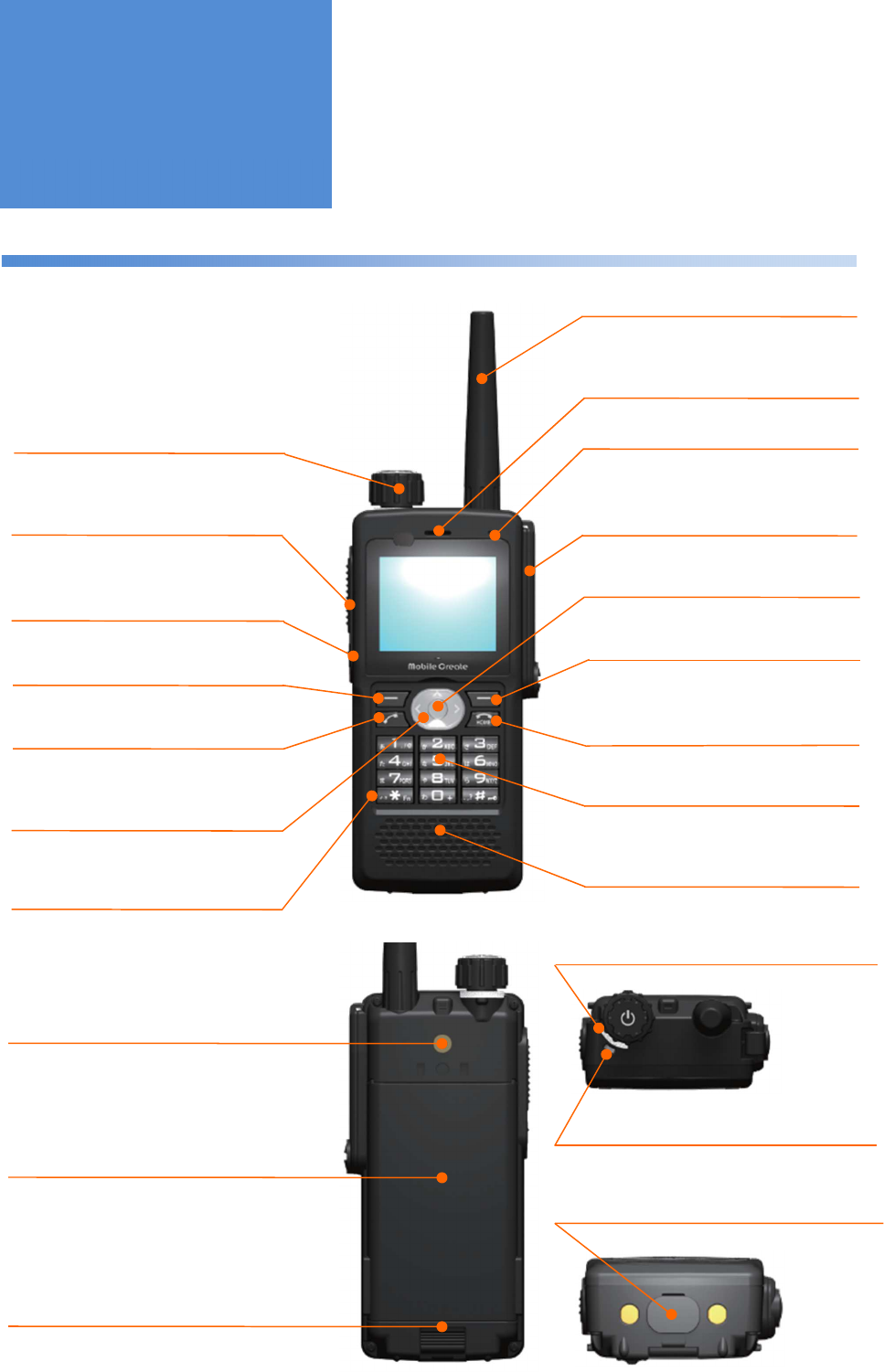
Main unit
OK Button
This button is used when finalizing a choice
and making a call.
Top Microphone
Talk toward this port during a call.
Ear Speaker
The sound transmitted from a counterpart
radio as well as sound effects are played
in silent mode
.
PTT Button
Pressing this PTT Button during a call
transmits sound to a counterpart radio.
Short
-
cut Button
Pressing this button enables
registered call modes or menus.
Upper Right Button
This button is used when selecting
menu functions.
Home Button
Pressing this button returns to the call mode
which was determined by call back mode
selection.
Front
Power/Volume Knob
Moving this knob up and down turns the
power on and off, turning it left and right
adjusts the sound volume.
Accessory Port
Remove the accessory cover and connect
a wired microphone to this port.
3G Antenna
Upper Left Button
Pressing this button enables switching
of
call modes.
Lower Left Button
This button is used mainly when
receiving a call.
Up,
Down, Left, Right Button
This button is used when adjusting
sound volume and selecting menu
functions.
Numeric Keypad
This keypad is used when entering a
number during individual cal
ls
.
Main Speaker
The sound transmitted from a counterpart
radio as well as sound effects are played.
2nd
Microphone
Talk toward this port during a call in
silent mode.
Functions of Parts
Rear
USB
P
ort
Remove the USB cap to connect a USB cable
to this port.
Rear
C
over
H
ook
This hook is used when removing the
battery pack.
Rear
C
over
This cover can be separated from the main
unit when removing the battery pack.
Charger LED
This LED displays the recharging status.
Belt Clip Attaching Port
This port is used when attaching the
belt clip.
Bottom
Status LED
This LED displays the current system
condition.
Top
- 10 -
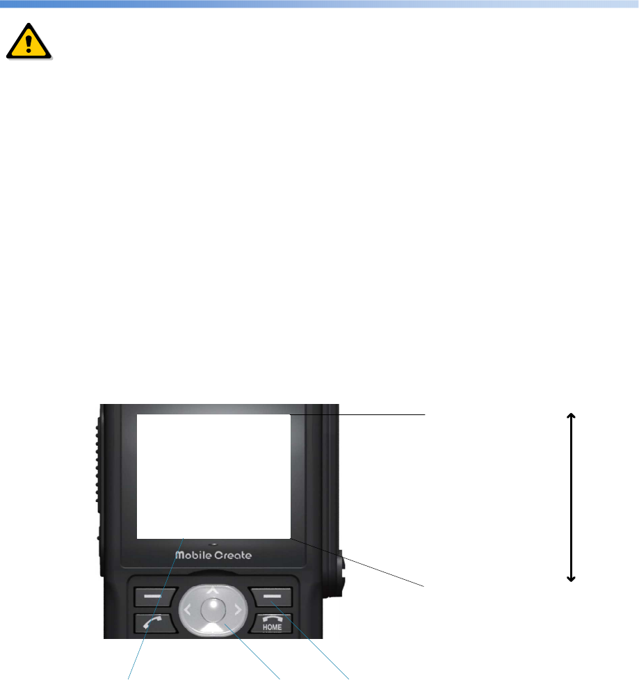
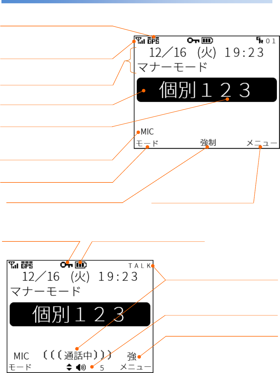
Display screen
Function of the Upper Left Button
The function of the upper left button is displayed.
Call Status
These are displayed during a call.
(Screen during a call)
Battery Status
The remaining battery level and external
power supply are displayed.
Function of the Up and Down/OK Button
The function of the up and down/OK button is displayed.
Function of the Upper Right Button
The function of the upper right button is
displayed.
Sound Volume
The sound volume of the speaker which is set to be
output is displayed.
During a call, pressing the up or down button changes
the sound volume
.
3G RSSI
The antenna reception level of the packet
communications network is displayed on a scale
of one to four.
Call Mode
The current call mode is displayed.
Selected Radio ID
The number of the radio ID which is selected
for the current call mode is displayed.
(Home screen)
External Microphone Connection
Status
The external microphone connection status is
displayed.
Key Lock Icon
This icon represents the status
when the keys are locked.
Break-in Call Status
This is displayed during a break-in call.
Ticker Function
Information such as time, manner mode, and
incoming call is displayed.
GPS RSSI
The reception level of the GPS receiving antenna is
displayed.
- 11 -
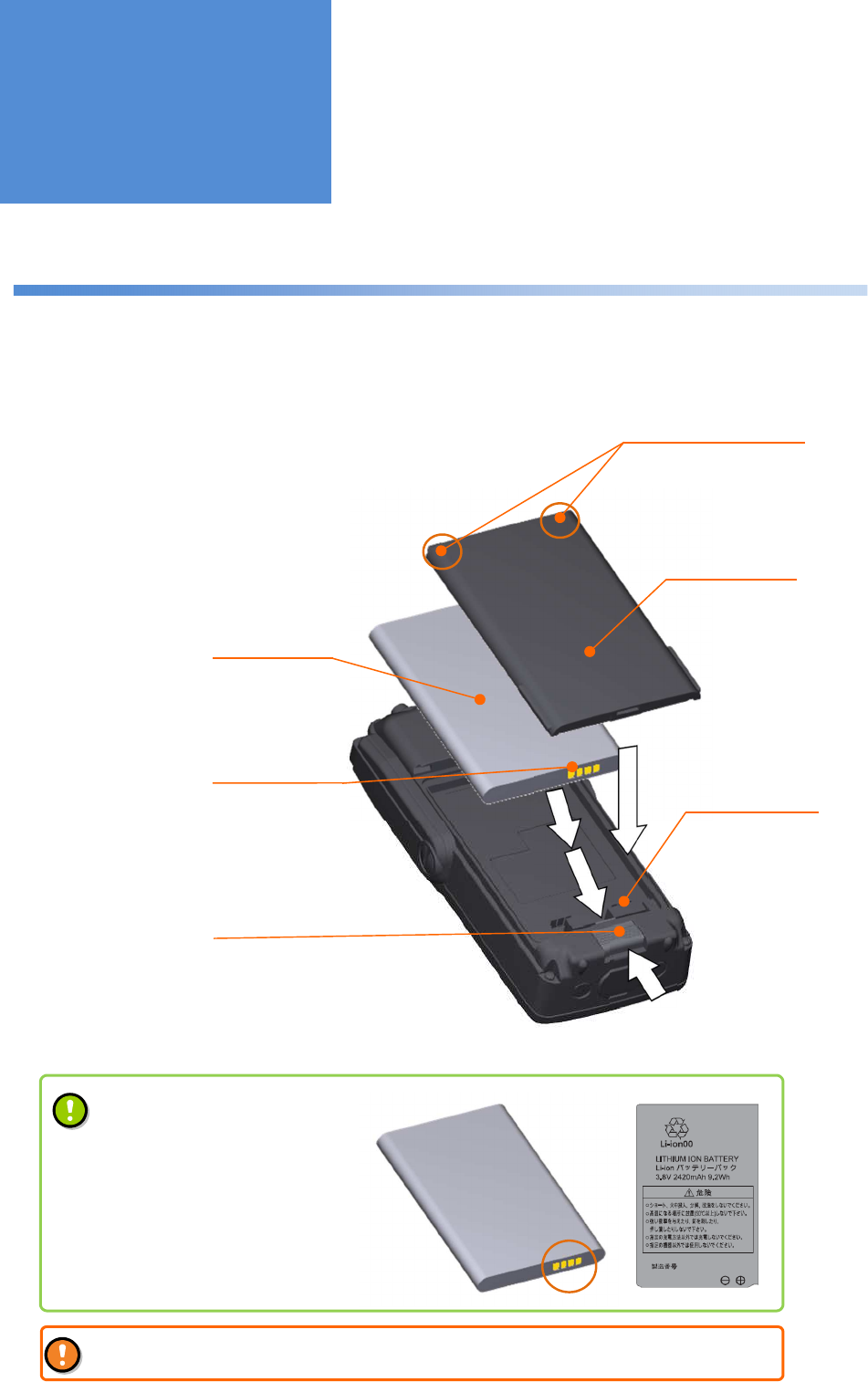
Attaching and detaching the battery pack
1:
2:
Attaching and
Detaching the
Battery Pack
Rear cover
Battery pack
Rear cover hook
Move the rear cover hook on the bottom down
to remove the rear cover.
Slide the battery pack down into the main unit with
the upper claw on the rear cover fit in the groove on
the rear cover hook of the main unit.
Upper claws on the
rear cover
Power supply terminal
on the main unit
Battery pack
terminal
Pay attention to the orientation
of the battery pack
The battery pack shall be attached in
such a way that the gold color terminal
on the bottom faces the lower right (as
shown in the figure on the left side) and
the letters can be seen as shown in the
figure on the right side.
Incorrect attachment of the battery pack could cause a failure or an unexpected accident.
- 12 -
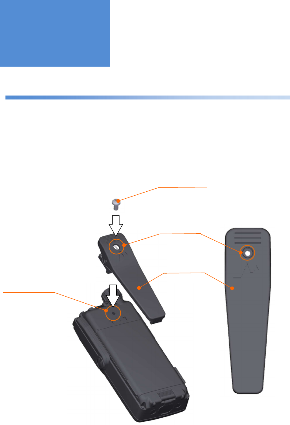
Attaching and detaching the belt clip
1:
2:
Loosen the belt clip screw to detach the belt clip.
With the belt clip hole aligned with the belt clip screw hole, put
the belt clip screw into the belt clip hole and tighten it.
Belt clip screw
Belt clip
Belt clip screw hole
Belt clip screw hole
Attaching and
Detaching the Belt
Clip
- 13 -
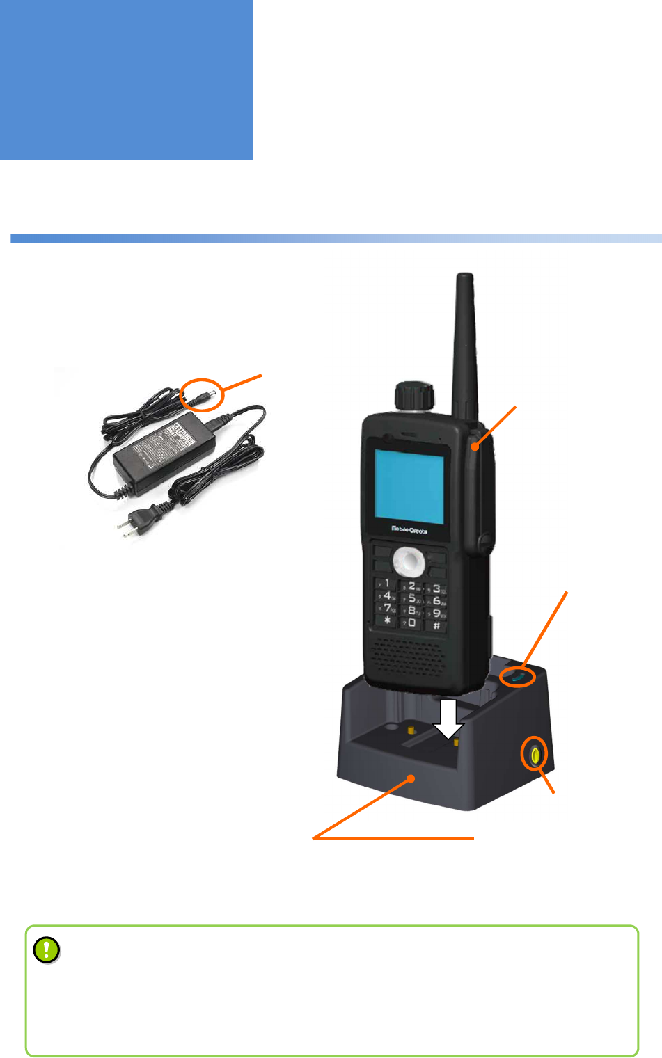
How to recharge the battery using a recharging cradle
1:
2:
3:
Recharging cradle
Connect the recharging cradle to the AC
adapter and then plug the AC adapter in a
100 V AC outlet.
On the recharging
cradle side
Dedicated AC adapter
AC adapter insertion port
Spare battery LED*
Off : The battery is not attached
: Recharging is completed
Red light : During recharging
Insert the main unit into the recharging
cradle with the guide on the recharging
cradle fit in the groove on the side of the
main unit.
The red charger LED on the main unit
lights up and then goes out when
recharging is completed.
* Used when the spare battery is
attached.
Recharging the
Battery
MPT-H1 (Main unit)
• It takes approximately 180 minutes to recharge the battery (when the main unit is off).
• Although communication can be performed during recharging, it takes longer to recharge the
battery depending on the communication conditions.
• Remove the power cord from the outlet after recharging is completed.
• For more details about the spare battery, please contact our distributor.
- 14 -
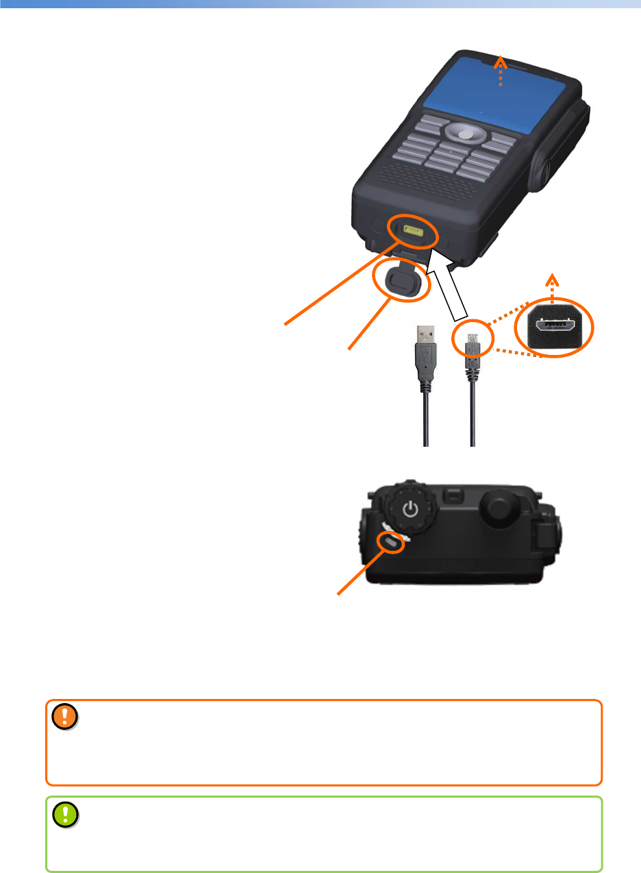
Recharging the battery through the micro-USB port
1:
2:
3:
Micro-USB connector
USB cap
The red charger LED on the top of the main
unit lights up and then goes out when
recharging is completed.
Male micro-USB
(Male micro-B)
Charger LED
Off : When the battery is not attached or
recharging is completed
Red light : During recharging
Open the cap (USB cap) on the bottom to find the
micro-USB connector (Female micro-B).
With the main unit facing front, connect a
general-purpose micro-USB cable to the
micro-USB connector.
Then, connect the opposite side of the
cable to a power supply (such as PC).
Front
Front
• Do not recharge without the battery pack in the main unit.
• Be sure to meet the following recharging conditions.
Operating temperature and humidity range of the charger:
0 to 40°C / 45 to 85% RH
• It takes approximately 360 minutes to recharge the battery (when the main unit is off).
• Although communication can be performed during recharging, it takes longer to
recharge the battery depending on the communication conditions.
- 15 -
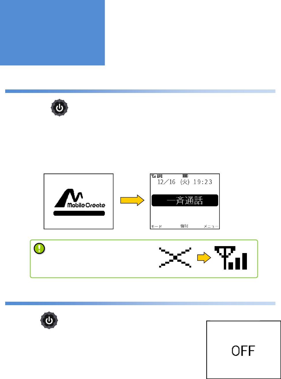
Turning the power on
1: Pressing the long until the status LED lights up vibrates the main unit and turns the power on.
2: The screen lights up and the start screen is displayed.
After a system check, the home screen is displayed.
Turning the power off
1: Press the long.
2: The main unit vibrates and displays the “OFF” message on the screen
before the power is turned off.
Turning the
Power On/Off
Start screen Home screen
Power-off screen
Power button
Power button
•
It requires some time to make a call after
the main unit is started up.
Check the RSSI displayed on the screen
before making a call.
- 16 -
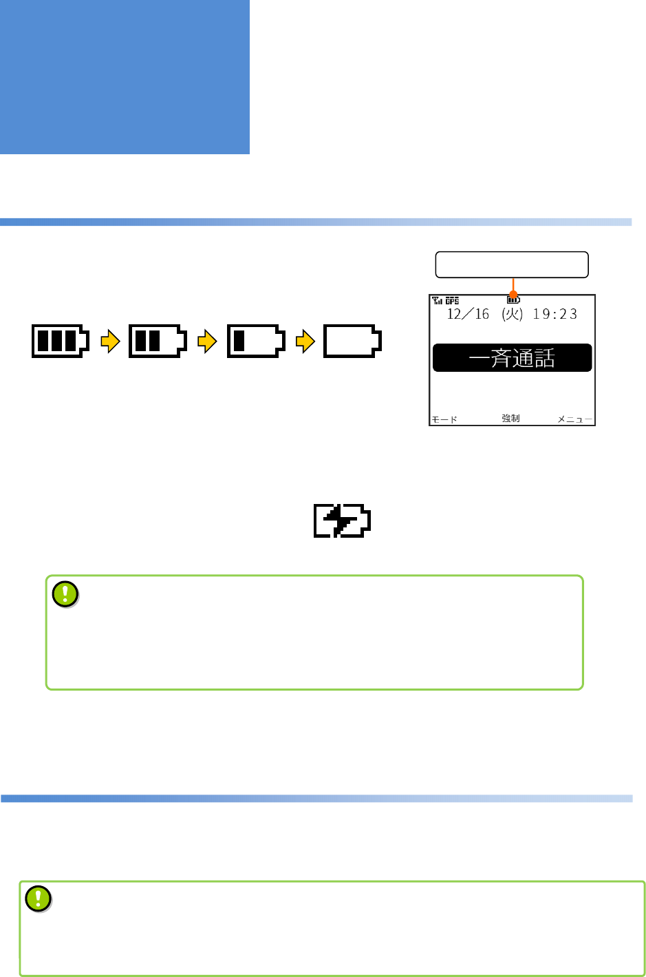
How to check the remaining battery level
During use, the remaining battery level is displayed on top of the
home screen.
The more the scale marks, the more of the battery remains.
When no scale marks are displayed and the red charger LED starts
flashing, recharge the battery with it mounted in the main unit or replace it
with a new one.
During recharging, the remaining battery level icon shows that recharging is underway.
Standby mode
Standby mode is a mode which cuts electric power consumption.
Remaining battery level
• The battery pack deteriorates after repeated electric recharge and discharge.
If the battery life is extremely shorter than before, replace with a new battery pack.
• Under low-temperature environment, the remaining battery level displayed may be
lower than the actual level.
Remaining
Battery Level
Home screen
• When Standby mode is on, the product is
switched to this mode if it is not operated for a preset
period of time.
How to set Standby mode [Menu] > [09:機能設定 (Utilities)] > [01:一般設定
(General Settings)] >
[05:エコモード設定 (Standby Setting)]
- 17 -
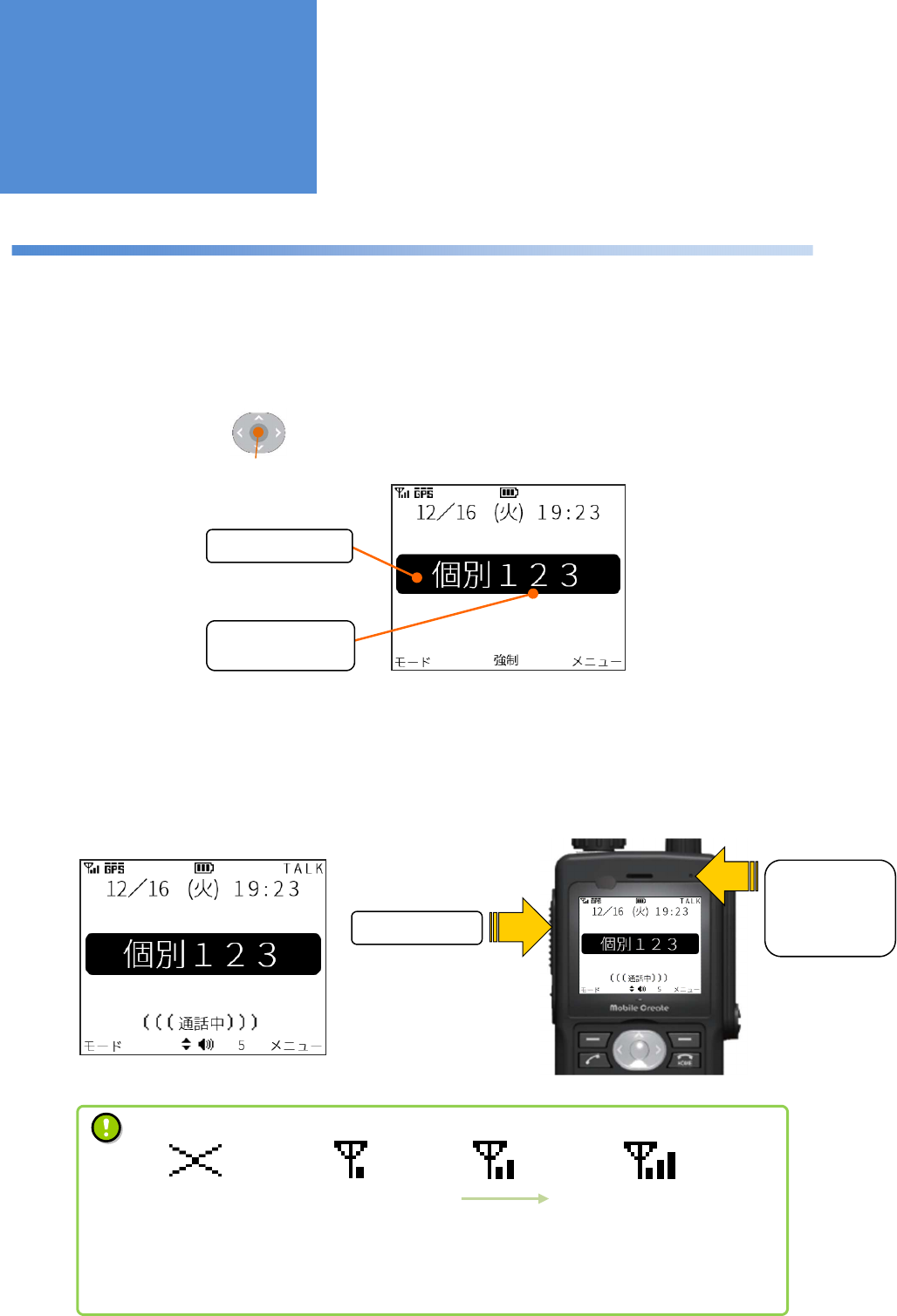
Making a call (outgoing)
A call can be made in the call mode selected on the screen.
For how to switch call modes, refer to “Switching call modes” on page 21.
1 : Check if the call mode and counterpart radio that you want to make a call to are correct and then press the
PTT button or the .
2 : After the “beep, beep, …” dialing tone, a blip sound is produced when the connection is completed.
3 : Speak into the microphone sound collecting port while pressing the PTT button.
Selected Radio ID
screen
Call mode
Counterpart radio
• RSSI is just a rough indication and does not assure the call quality.
The flow of conversing voices may be interrupted during a call even when the radio
wave signal is strong.
RSSI
No service Weak radio wave signal Stronger radio wave signal
(Before connection)
PTT Button
Top
microphone
sound
collecting port
OK button
Screen displayed during a call
Making/Receiving
a Call
- 18 -
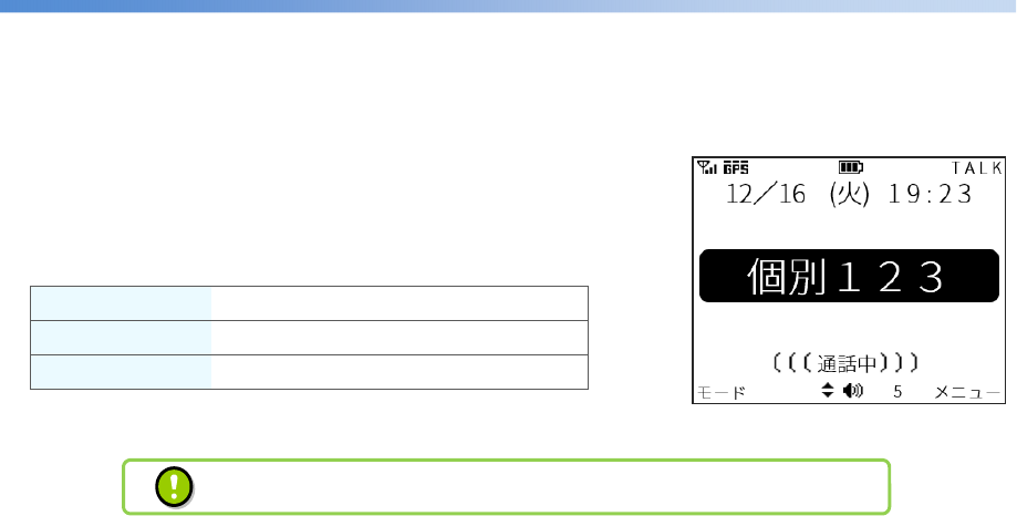
Receiving a call (incoming)
1: After a blip ring tone, the call mode is displayed on the screen.
2: You can talk while long-pressing the PTT button.
■
Ring tones for different call modes
Individual Call Ring tone “Boop blip”
Break-in Calls Ring tone “Boop boop blip”
Group Calls Ring tone “Blip
Incoming call screen
Other kinds of group calls: Group call, all call, and dispatcher call, etc.
- 19 -
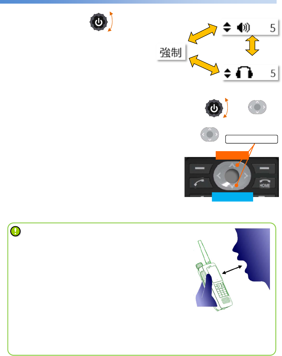
Changing the sound volume
On the home screen, turning the switches the “Break-in” message
displayed at the bottom of the screen to “Main speaker”
or “Ear speaker” icons as shown in the Figure on the
right to enable the volume to be changed.
While the main speaker icon is displayed, the volume can be changed with the or the .
While the ear speaker icon is displayed, the volume can be changed with the .
Setting the volume to zero activates silent mode.
The volume can also be changed during a call or on the volume
settings screen in the menu
Break-in call setting display
Turn up
Turn down
Ear speaker icon
Volume knob
Up/down
button
Volume knob
Up/down button
The
change in screen when the
volume is changed
Up/down button
Main speaker icon
To talk with better sound
When talking, keep the product approximately 5 cm away
from the
mouth.
Talking very close to the product
may crack or distort the voice sound
delivered to the counterpart.
The
sensitivity of the microphone can be changed from the Menu as
follows:
How to change the microphone sensitivity:
[Menu] > [09:機能設定 (Utilities)] > [03:音質設定 (Voice Qualities
)] >
[02:マイク感度 (Mic Sensitivity)]
According to the voice volume, change the quality o
f voice to one
which is friendly to the counterpart.
- 20 -
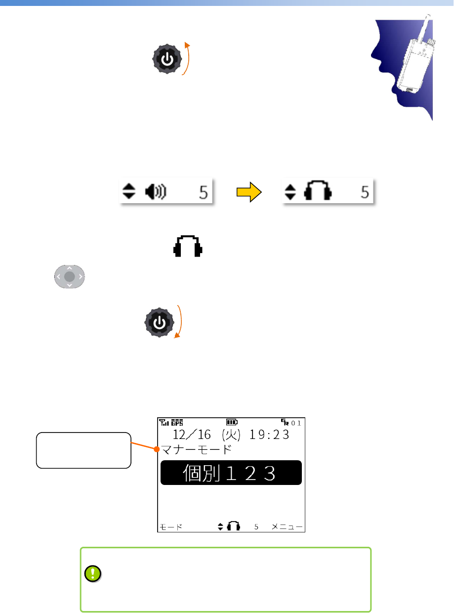
Silent mode
Silent mode is a mode which makes call with next to the ear.
On the home screen, turning the counterclockwise changes from
the main speaker icon to the ear speaker icon as shown in the Figure below
and silent mode is activated. In silent mode, the top microphone input
and main speaker output are switched to the 2nd microphone input and ear speaker output, respectively.
While the volume is displayed with the icon, the ear speaker volume can be turned up and down
using the .
To cancel silent mode, turn the clockwise on the home screen.
On the home screen during silent mode, the “silent mode” ticker is displayed.
Volume knob
Home
screen during
silent mode
Displaying the
silent mode ticker
Up/down button
Volume knob
Switched to silent mode
When the vibrator is enabled,
• The vibrator operates when switched to silent mode.
•
When a call is incoming, the vibrator operates according to a
preset vibrating pattern.
Call position on silent mode
- 21 -
A wide variety of call modes
■
Standard call modes
Individual call This mode enables talking to an another radio on a one-to-one basis.
Dispatcher call This mode enables talking to all dispatchers in the group simultaneously.
All call This mode enables talking to all radios together.
Group call This mode enables talking to all radios in the group simultaneously.
Channel call This mode enables talking to radios registered with the same channel number.
Talkaround call This mode enables talking to radios in a user who exist within a predetermined
distance centering around the mobile radio of the caller.
■
Interrupt call modes
Break-in individual call This mode forcibly terminates a radio during a call and makes it join an
individual call.
Break-in dispatcher call
This mode forcibly terminates a dispatcher during a call and makes it join a
dispatcher call.
Break-in all call This mode forcibly terminates radios during a call and makes them join an all
call.
Break-in group call This mode forcibly terminates radios in the group during a call and makes
them join a group call.
Break-in channel call This mode forcibly terminates radios within the same channel number during
a call and makes them join a channel call.
Break-in all dispatcher
call
This mode forcibly terminates all dispatchers during a call and makes them
join an all dispatcher call.
■
Special-purpose call mode
All dispatcher call This mode enables talking to all dispatchers including those in different
groups.
• Adding or changing call modes requires setting by a
dealer.
C
ontact a dealer
for details
.
Making a Call
- 22 -
Switching call modes
■
In the case of an individual call
1: Entering a radio ID with the numeric keypad on the home screen switches to individual call mode.
However, if the home screen is in channel call mode, enter a channel number.
■
In the case of other call modes
1: Pressing the on the home screen switches among call modes.
Call modes are switched in the order they are registered.
Upper left button
Numeric keypad Individual call mode
How to switch between call modes
• The call modes that you want to use need to be registered in advance.
•
Contact a dealer if you want to change the order in which call modes are switched or to add or
change call modes.
Dispatcher call
mode
Channel call mode
All call mode
Every time the upper left button is pressed, call modes are switched in the order
they are registered.
Press
buttons
Press the button
- 23 -
Register group ID function
■
How to set this function
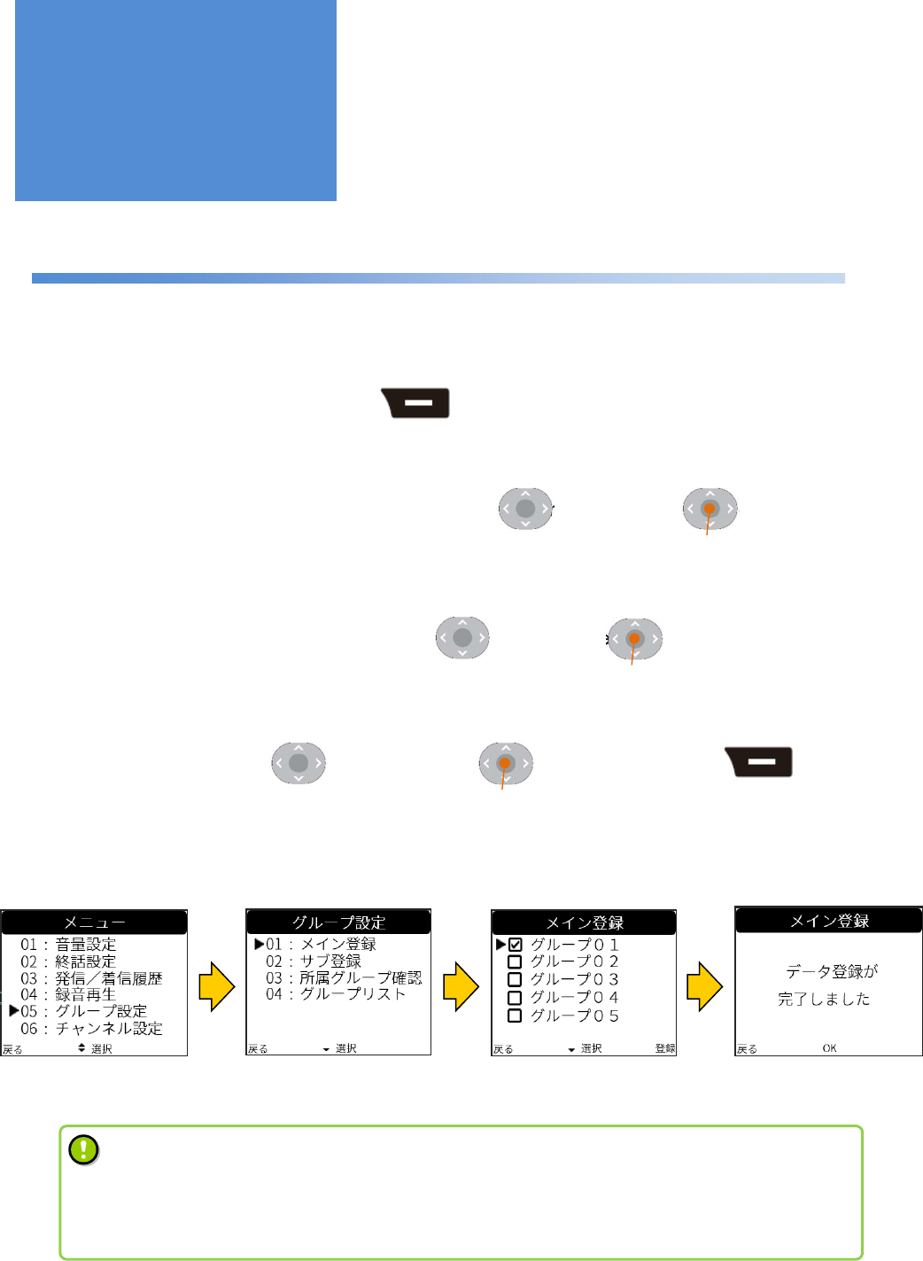
1: Switch to the [Menu] screen using the .
2: Choose [05:グループ設定 (Group Settings)] using the and press the to go to the setting
screen.
3: Choose [01:メイン登録 (Main Group)] using the and press the to go to the registration
screen.
4: Choose a group using the , check it using the , and register it using the .
Group ID registration
screen
Main group ID registration
screen
Registration completion
screen
Upper right button
Useful Functions
Menu screen
Up/down button OK button
Up/down button OK button
Up/down button OK button Upper right button
•
Since group ID registration requires packet transfer communication, registration may fail if radio
wave signals are weak. If it fails, try the registration again.
• This function may not be usable depending on the type of system you use.
Contact a dealer for details.
- 24 -
Channel selection function
■
How to set this function
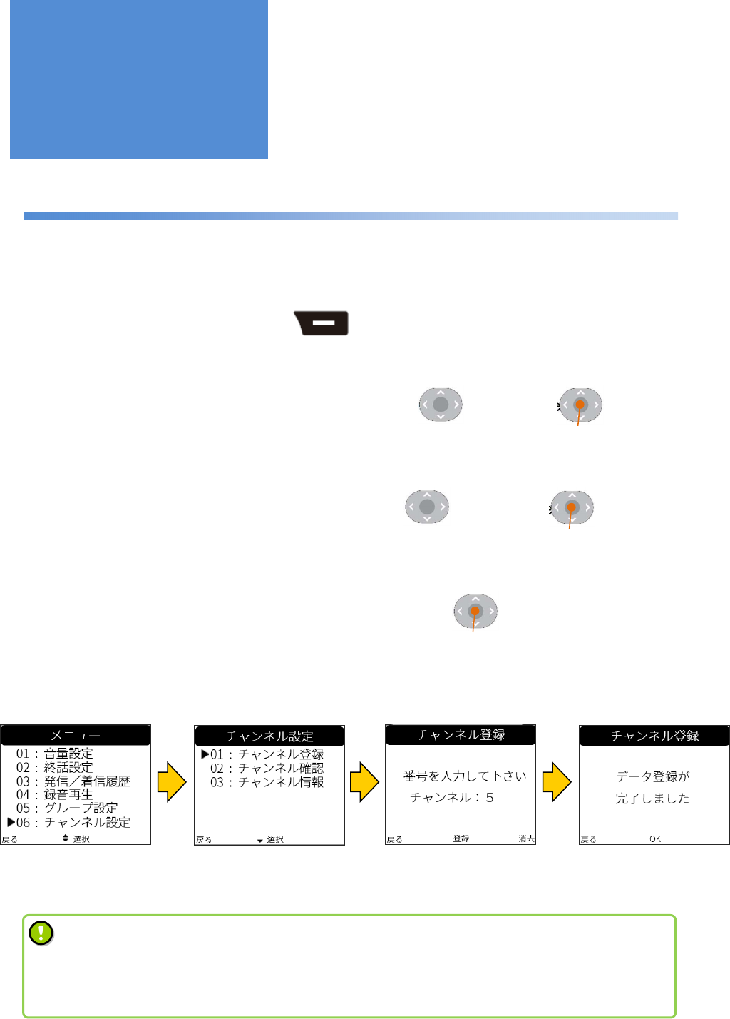
1: Switch to the [Menu] screen using the .
2: Choose [06:チャンネル設定 (Channel Settings)] using the and press the to go to the
setting screen.
3: Choose [01:チャンネル登録 (Set Channel)] using the and press the to go to the
registration screen.
4: Enter a channel number using the numeric keypad and press the to register it.
Menu screen
Register button
Up/down button OK button
Up/down button OK button
Upper right button
•
Since channel selection requires packet transfer communication, selection may fail if radio wave
signals are weak. If it fails, try the selection again.
• This function may not be usable depending on the type of device you have.
Contact a dealer for details.
Channel number
registration screen
Registration
completion
screen
Channel selection
screen
Useful Functions
- 25 -
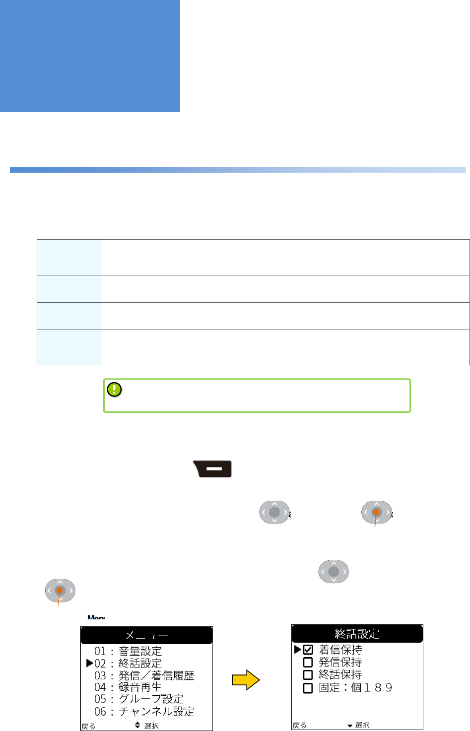
Call back mode selection function
The radio displayed on the home screen after a call can be changed according to the following procedure:
■
Call back mode selection
Received
call mode The mode of the call received from a counterpart radio is retained after a call.
In the case of an individual call, the radio ID is also retained.
Transmitted
call mode The radio ID and mode of the call that you made are retained after a call.
Previous call
mode Irrespective of whether an incoming or outgoing call, the radio ID and mode of the last
call are retained after a call.
Initial call
mode After a call, the radio ID and call modes are switched to those set here.
Any individual radio and call mode which are already registered can be chosen.
■
How to set this function
1: Switch to the [Menu] screen using the .
2: Choose [02:終話設定 (Call Back Mode)] using the and press the to go to the call back
mode selection screen
3: Choose the call back mode selection that you want to set using the and check it with the
to complete the selection.
The call mode which is set as the
initial call mode needs to be
registered in advance. Contact a dealer for details.
Menu screen Call back mode selection screen
Upper right button
Up/down button OK button
Up/down button
OK button
Useful Functions
- 26 -
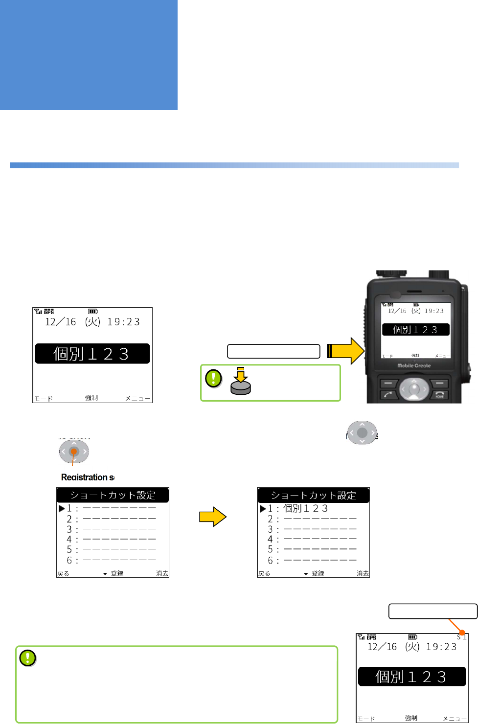
Short-cut function
Registering short-cuts for call modes, individual radios, and menus which are frequently used enables them to
be easily invoked. Up to ten short-cuts can be registered.
■
How to register a short-cut
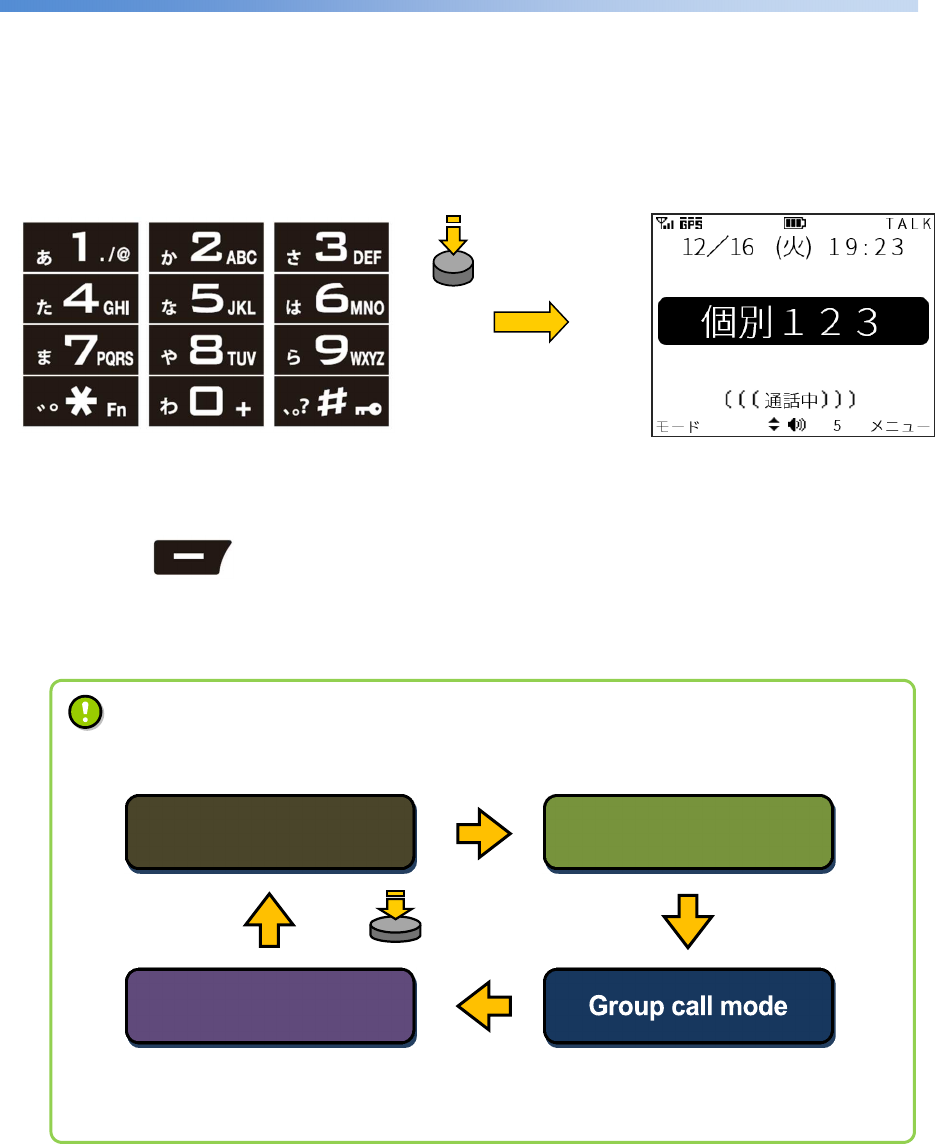
(Example: Registering a short-cut for the No. 123 individual radio)
1: Long-press the short-cut button while the No. 123 individual radios is selected.
2: When the short-cut registration screen is displayed, choose with the and register with the .
■
How to invoke a short-cut
1: Pressing the short-cut button switches the screens in the order they are
registered.
Short-cut screen
Short-cut button
Registration screen Registration screen
Individual call selection screen
S
hort
-
cut
display
Up/down button
OK button
• If multiple numbers of short-
cuts are registered, they are invoked in
ascending order.
• Short-cuts may not be usable depending on the type of
device
used.
Contact a dealer for details.
Useful Functions
Long-press this
button
- 27 -
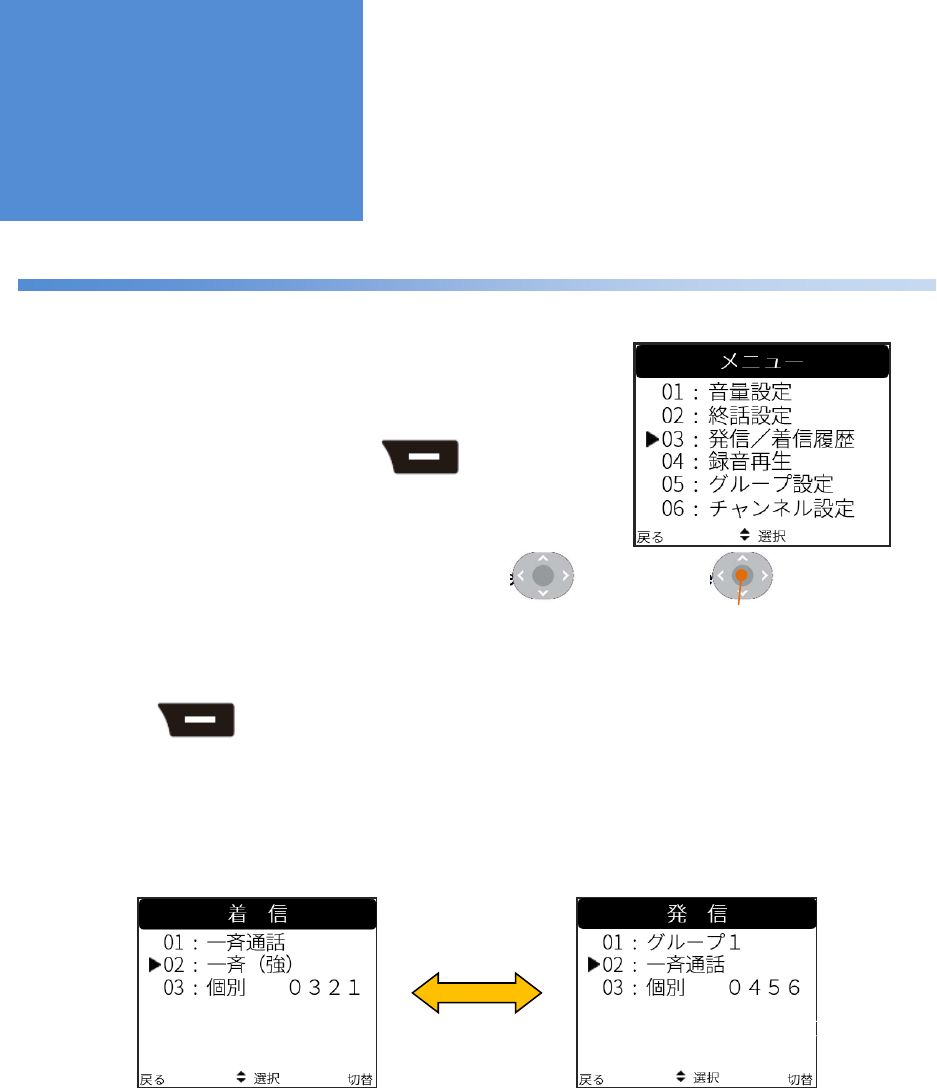
Talk history function
Up to ten received and transmitted calls are saved, respectively.
■
How to display the talk history
1: Switch to the [Menu] screen using the .
2: Choose [03:発信/着信履歴 (Talk History)] using the and press the to switch between
screens.
3: Press the to switch between the received call history and the transmitted call history.
Switch with the upper
right button
Menu screen
Received call history
Transmitted
call
history
Upper right button
Upper right button
Up/down button OK button
Useful Functions
- 28 -
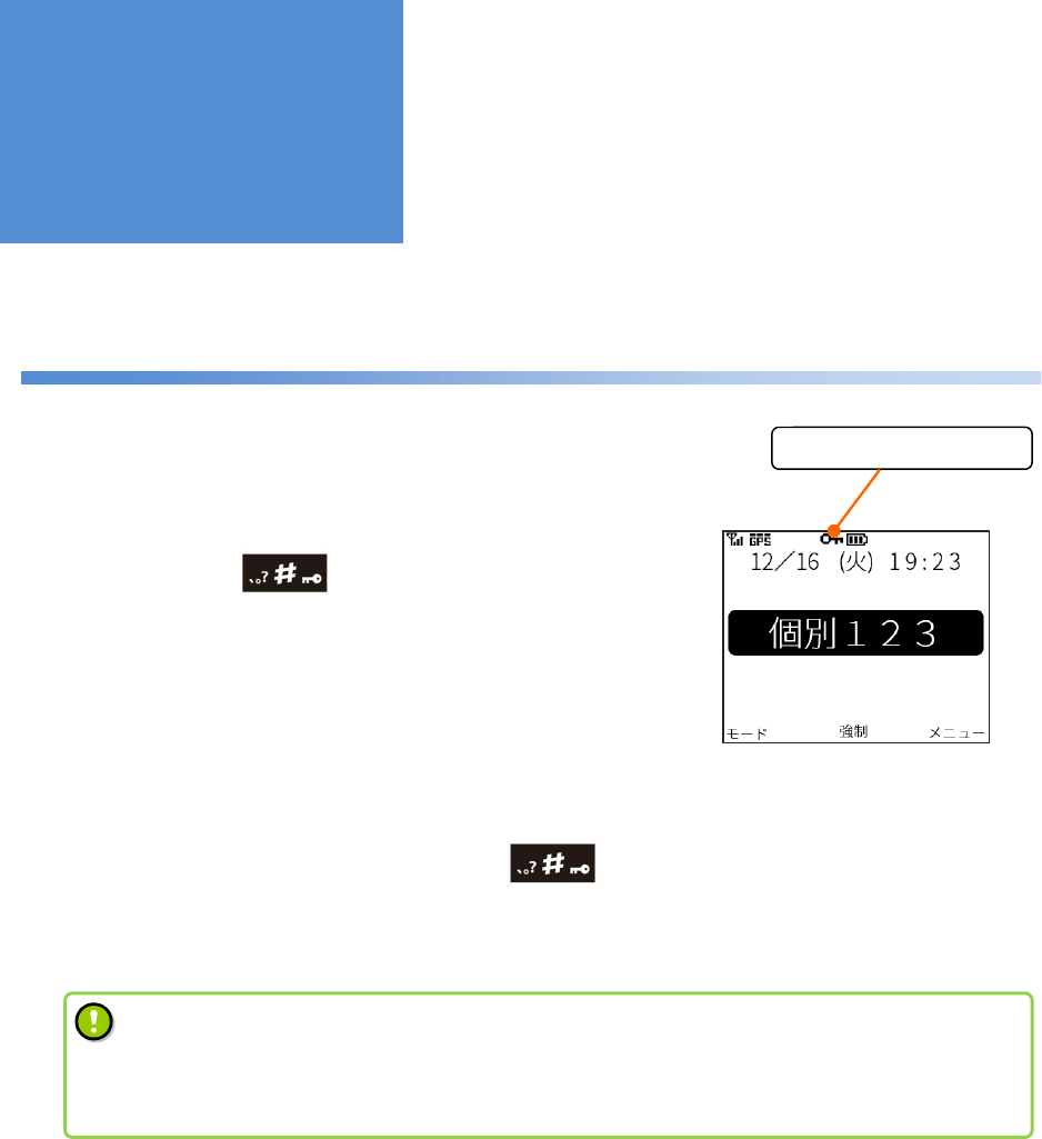
Key-lock function
This function disables key input to prevent malfunction during transportation.
■
How to set this function
1: Long-pressing the included in the numeric keypad
on the home screen activates the key-lock function.
However, the power/volume knob is kept enabled even in the key-
lock state.
■
How to cancel this function
2 : To cancel the key-lock function, long-press the included in the numeric keypad again.
Key-lock screen
# button
Display of key-lock state
# button
• Calls can be received even in the state where the keys are locked.
• Although the key-
lock function is cancelled temporarily when a call is received, it is enabled
again after the call.
Useful Functions
- 29 -
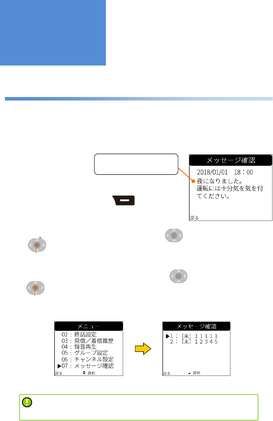
Text message function
If the dynamic control service has been introduced, text messages can be sent to individual radios from a
computer.
The text messages received can be checked again from the menu.
■
How to check text messages again
1: Switch to the [Menu] screen using the .
2: Choose [07:メッセージ確認 (Text Message)] using the and switch among screens using
the .
3: Choose the text message that you want to check using the and switch among screens using
the .
Text message receipt screen
Menu screen Test message selection screen
Upper right button
べんりな機能
Up/down button
OK button
Up/down button
OK button
• The dynamic control service needs to be applied for. Contact a dealer for details.
• Up to ten text messages received are stored and can be checked from the menu.
Useful Functions
It is nighttime now. Please
take care when driving.
- 30 -
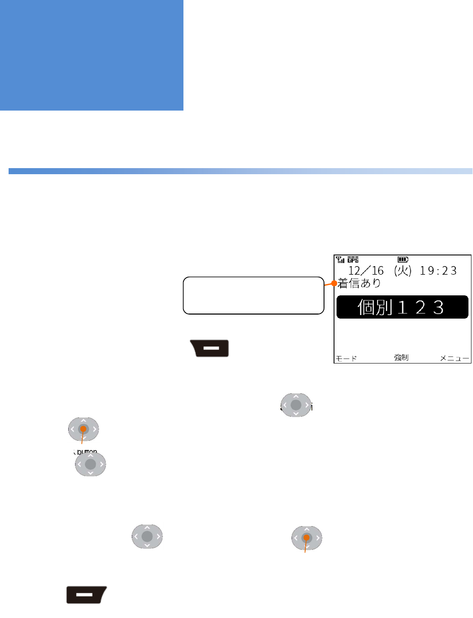
Call back function
If the main unit is not operated during an individual call, the “着信あり” message is displayed on the home screen.
To make a call to a caller, press the PTT button or the OK button.
■
How to set this function
1: Switch to the [Menu] screen using the .
2: Choose [08:コールバック (Call Options)] using the and switch among screens using the .
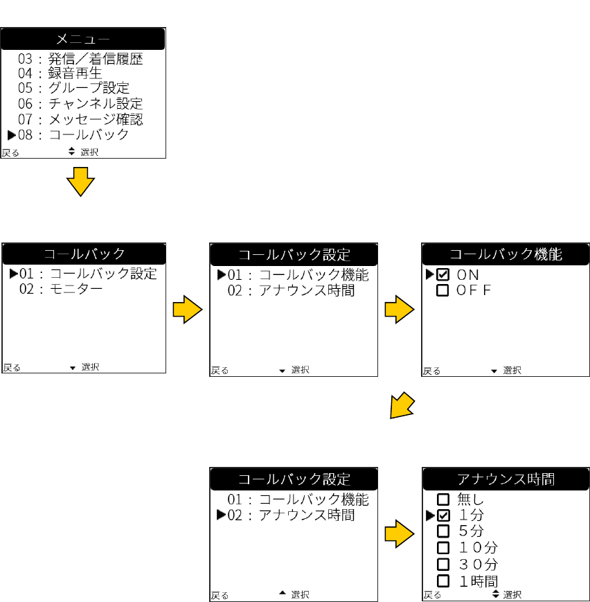
3: Press the to select [01:コールバック設定 (CallBackSettings)] and [01:コールバック機能
(On/Off)] and switch between screens.
4: Choosing “ON” with the and checking a call with the set this function.
5: Press the to switch the screen and choose [02:アナウンス時間 (Alert Timer)] to set
the notification timer using the announce sound effect. The [アナウンス時間 (Alert Timer)] setting is disabled
when the main unit is switched to standby mode.
Home
screen: If you had a call
Upper left button
Upper right button
べんりな機能
“The “You have a missed
call.” message is displayed
Up/down button
OK button
Up/down button
Up/down button OK button
Useful Functions
- 31 -
Call back selection
screen
Menu screen
Call back setting screen
(Selecting 01)
Call back function
screen
Call back setting screen
(Selecting 02) Alert timer screen
- 32 -
Vibration function
The vibrator operates when a call is received and a mode is changed.
• If the vibration function is on, a vibration pattern is executed once in the event of “power on,”
“power
off,” “receipt of call,” “call back,” and “no battery remained.”
How to set this function
[Menu] > [09:機能設定 (Utilities)] > [01:一般設定 (General Settings)] > [02
:バイブ設定
(Vibration)]
• Different vibration patterns can be set depending on the type of call:
Individual Call : No vibration + three vibration patterns
Break-in Calls : No vibration + three vibration patterns
Group Calls : No vibration + three vibration patterns
How to set a vibration pattern when a call is received
[Menu] > [09:機能設定 (Utilities)] > [01:一般設定 (General Settings)] > [04
:着信設定
(Receiving Call)] > [01:着信バイブ設定 (Vibration)]
• The vibrator operates when the main unit is switched to silent mode with the vibration function on.
Useful Functions

- 33 -
Menu function
■
Menu
01:音量設定 (Volume Settings) The speaker volume can be changed (0 to 20).
01:メイン (Main) The main speaker volume can be set.
02:イヤー (Ear) The ear speaker volume can be set.
03:ハンド (Remote Speaker) The speaker volume of the speaker microphone can be set.
04:イヤホン (Headphone) The head set speaker volume can be set.
02:終話設定 (Call Back Mode) The call mode displayed on the home screen after a call can be changed
□ 着信保持 (Received call) The mode of the call received from a counterpart radio is retained after a call.
In the case of an individual call, the radio ID is also retained.
□ 発信保持 (Transmitted call) The radio ID and mode of the call that you made are retained after a call.
□ 終話保持 (Previous call) Irrespective of whether an incoming or outgoing call, the radio ID and mode
of the last call is retained after a call.
□ 固定 (Fixed): グループ (Group) After a call, the radio ID and call modes are switched to those set here.
Any individual radio and call mode which are already registered can be
chosen.
03:発信 / 着信履歴 (Talk History) The talk history of each of ten past incoming and ongoing calls can be
checked.
04:録音再生 (Record Settings) The ten most recent calls are recorded (the voice sound of the counterpart
radio only).
01:音声メモ (Save) The ten most recent recorded calls can be displayed, played, and saved.
02:保存録音 (Play) Saved calls can be displayed and played.
05:グループ設定 (Group Settings) The call group that you want to belong to can be set.
01:メイン登録 (Main Group) The main group that you want to belong to can be set.
02:サブ登録 (Sub Group) The sub group that you want to belong to can be set.
03:所属グループ確認 (My Group) The main and sub groups that you now belong to can be displayed.
04:グループリスト (Group List) The list of all groups can be displayed.
06:チャンネル設定 (Channel Settings) Channels can be set.
01:チャンネル登録 (Set Channel) The channel that you want to belong to can be set.
02:チャンネル確認 (My Channel) The channel that you now belong to can be displayed.
03:チャンネル情報 (Channel List) The list of up to 50 radio IDs for the channels that you now belong to can be
displayed.
07:メッセージ確認 (Text Message) The ten most recent text messages received can be checked.
08:コールバック (Call Options) The call back function and the remote monitor can be set.
01:コールバック設定 (CallBackSettings) The call back function can be set.
02:モニター (Remote Monitor) The remote monitor can be set.
Useful Functions

- 34 -
09:機能設定 (Utilities) A wide variety of functions can be set.
01:一般設定 (General Settings) Settings can be reset.
01:ホーム設定 (Home setting) The call or location display of the home screen can be selected.
02:バイブ設定 (Vibration) The vibrator can be enabled/disabled.
03:マイク接続設定 (Multi Point CN) Any one of “no microphone connection”, “Top microphone”, and “2nd
microphone” can be selected.
04:着信設定 (Receiving Call) The blocking of incoming calls and vibration in the event of the receipt of
a call can be set.
01:着信バイブ設定 (Vibration) Vibration patterns for each call mode can be set.
01:個別通話 (Individual Call) Any one of “no vibration” and patterns 1-3 can be selected.
02:強制系通話 (Break-in Calls) Any one of “no vibration” and patterns 1-3 can be selected.
03:その他同報系通話 (Group Calls)
Any one of “no vibration” and patterns 1-3 can be selected.
02:拒否通話モード (Block Incoming) The blocking of incoming calls can be set.
05:エコモード設定 (Standby Setting) The starting time of standby mode can be set.
06:USB 接続設定 (USB Setting) USB communication can be selected.
07:設定リセット (ResetAllSettings) All settings can be returned to default values.
02:ショートカット (Short Cuts) The list of registered short-cuts can be displayed or cancelled.
03:音質設定 (Voice Qualities) The equalizer function and microphone sensitivity can be adjusted.
01:スピーカ音質 (Speaker Quality) The sound equalizer function can be selected.
02:マイク感度 (Mic Sensitivity) Microphone sensitivity can be changed.
04:表示・照明設定 (Display Settings) The screen display and light can be set.
01:コントラスト (Contrast) The screen contrast can be adjusted.
02:キーバックライト (Key Back Light) The key back light can be turned on/off.
03:バックライト (LCD Back Light) The LCD back light can be turned on/off.
04:バックライト色 (LCD BL Color) The LCD back light color can be set.
05:照度センサ (Illuminance) The illuminance sensor can be turned on/off.
05:効果音設定 (Sound Effects) Effective sounds can be enabled/disabled.
01:起動音 (Boot Sound) The boot sound can be enabled/disabled.
02:キータッチ音 (Key Touch Tone) The key touch sound can be enabled/disabled.
03:メッセージ受信音 (Message Tone) Whether the test message receipt sound is produced only once or
continuously can be selected.
04 : 通 話 モ ー ド 選 択 音 (CallMode
Announce)) The call mode announce sound can be enabled/disabled.
05:効果音音量 (Volume) The volume balance of effective sounds can be set.
06:通話関連 (Call) The call-related sounds can be turned on/off.
01:コール音 (Call Tone) Can be turned on/off.
02:プレス音 (PTT Tone) Can be turned on/off.
03:プレス解放音・ザ(Talk Permit
Tone) Can be turned on/off.
04:接続音 (Connect Tone) Can be turned on/off.
05:切断音 (Disconnect Tone) Can be turned on/off.
06:機器状態確認 (System Status) The status of the network and system can be checked.
01:システム時刻 (System Clock) The time of receipt can be displayed.
02:GPS 状態 (GPS status) The GPS receiving status can be displayed.
01:測位状態 (Receiving Status) The status can be displayed.
02:緯度経度 (Lat/Lon) The status can be displayed.
- 35 -
03:速度/方位/高度 (Spd/Deg/Alt) The status can be displayed.
04:GPS 時刻 (GPS Time) The time can be displayed.
05:受信レベル (GPS RSSI) The level can be displayed.
03:ネットワーク状態 (Network Status) The RSSI and communication status of 3G packet communication can
be displayed.
01:アンテナレベル (3G RSSI) The status can be displayed.
02:通信状態 (3G Condition) The status can be displayed.
03 : モ ジ ュ ー ル 状 態 (Module
Condition)
The status of the 3G module can be displayed.
04:電源電圧・電流 (Voltage/Current) The status of the power voltage and current which are supplied to the
main unit can be displayed.
05 : 外 部 接 続 機 器 状 態 (Device
Condition) The current status of the device can be displayed.
01:各種キー (Key Checker) The keys which are pressed can be displayed.
02:USB 接続状態 (USB) The USB connection status can be displayed.
03:充電状態 (Charge) The status of power supply and charge can be displayed.
06:マイクテスト(Microphone Test)
Pressing the PTT button can start recording and releasing it can
play the recorded sound.
07:IP アドレス (IP Address) The IP address of this system can be displayed.
08:バージョン情報 (System Info)
The software version and serial number can be displayed.
01:ソフトバージョン (Software
Ver.) The firmware version of this radio can be displayed.
02:シリアルナンバー (Serial
Number)
The serial number of this radio can be displayed.
03:認証情報 (Regulatory) The technology conformance mark can be displayed.
04:3G ファーム (3G Firmware)
The firmware version of the 3G module can be displayed.
07:メンテナンス This function is used by a retailer when various settings are
configured and requires a password.
Some functions may not be used depending on the type of system used. Contact a dealer for details.

- 36 -
If you suspect a failure
If you suspect a failure, check the following.
If the problem still cannot be solved, contact a dealer.
The power cannot be
turned on
■ If the length of time of pressing the power button is too short, the system does not start
up. Long-press the power button until the status LED lights up.
■ Check if the battery pack is attached properly.
■ If the remaining battery level is insufficient, the system cannot start up. Recharge the
battery or replace it with a new one.
The buttons cannot be
operated
■ If the key-lock function is enabled, the buttons cannot be operated. Check whether the
key-lock function is enabled.
In spite of trying to
make a call, you have
trouble getting through
to a counterpart
■ If any of the following messages are displayed on the screen, take the following actions:
「通話中です。 しばらくしてからかけ直してください。」
“Receiver is on another session.Call back later. ”
This message is displayed when the counterpart radio is on the line. Make a call again later.
「電源が入っていないか電波がとどかないためつながりません。」
“
No reply.Receivers are out of range or powered off.
”
The counterpart radio is switched off or out of the service area.
Make a call again later.
「該当する無線局が存在しません。」
“
Error.Wrong Number.
”
This wireless radio ID is not registered with the system. Check if the number of the counterpart
radio is correct.
「電波状況が悪いため発信できませんでした。」
”Out of range.Can't connect to voice server. ”
Check the RSSI of the microphone and make a call again in a place where the radio wave signal
is strong.
「接続できませんでした。 しばらくしてからかけ直してください。」
「現在、通話できません。 しばらくしてからかけ直してください。」
“Out of range.Can't connect to voice server. ”
“Can't call now.Call back later. ”
There is the possibility of a network failure. Make a call again later.
Troubleshooting

- 37 -
You have trouble
transmitting your voice
■ The sound quality may be deteriorated if your mouth is too close to the microphone sound
collecting port. Keep the product approximately 5 cm away when you talk.
■ Be careful not to put your fingers on the microphone sound collecting port.
■ The microphone sensitivity can be changed from Utilities in the menu. Adjust the
microphone sensitivity according to the loudness of the voice.
How to adjust the microphone sensitivity: [Menu] > [09:機能設定 (Utilities)] > [03:音質設定 (Voice
Quality)] > [02:マイク感度 (Mic Sensitivity)]
You have trouble
hearing the voice of a
counterpart
■ Check to see if the volume setting is too small.
■ Be careful not to put your hand on the speaker.
■ The sound quality of the speaker can be changed from Utilities in the menu. You can
change to an ear-friendly sound quality according to the surrounding environment.
How to adjust the sound quality: [Menu] > [09:機能設定 (Utilities)] > [03:音質設定 (Voice Quality)]
> [01:スピーカ音質 (Speaker Quality)]
The battery cannot be
recharged
■ Check if the power cord is properly connected to the recharging cradle and the electric
outlet.
■ Check if the USB cable is properly connected (at the time of recharging through USB).
■ Check if the battery pack is attached properly.
■
Principal Specifications
Dimensions
W 54 × D 30 × H 123 mm (excluding projections)
Weight
240 g (with the battery pack)
Power-supply voltage
Power supplied from the recharging cradle: 5.5 V DC (Maximum current: 2 A)
Power supplied from USB: 5.0 V DC (Maximum current: 500 mA)
Provided battery pack: 3.8 V DC (2,420 mAh)
Consumption current
During transmission/reception: 350 mA (Up to 500 mA)
During standby: 260 mA
Serviceable time
[Normal mode] Approximately 9 hours (if the ratio of reception : transmission :
standby is 1:1:8)
[Standby mode] Approximately 13 hours (Same as above)
Note: Recharging time: Approximately 180 minutes (when the power is off and
the cradle is used)
Surrounding
environment
Operational temperature: - 20°C to 60°C (During recharge: 0 °C – 40 °C)
Communication
method
3G (HSPA) 800 / 2100 MHz
Transmission output
Up to 0.25 W
Transmission rate
Receiving: 14.4 Mbps (HSDPA) / 384 kbps (W-CDMA) (Maximum)
Sending: 5.7 Mbps (HSUPA) / 384 kbps (W-CDMA) (Maximum)
GPS
Equipped
Speaker output
2 systems: Main speaker of 1W, ear receiver of 0.01 W
Water-proof and dust-
proof properties
Equivalent to IP67
Mobile Create USA, Inc.
#658, 2033 Gateway Place, San Jose, California, U.S.A. 95110
■ Reproducing, copying, or modifying this document, in whole or in part, without permission is prohibited.
■ The specifications, design, and other information contained in this document are
subject to change for improvement
without prior notice.