MS Sedco 608 Manual 102017 Series Installation Instructions
User Manual: MS Sedco MS Sedco 608 Series Installation Instructions Installation Instructions
Open the PDF directly: View PDF ![]() .
.
Page Count: 2
608 Series
Heavy Duty Switch Bollard INSTALLATION INSTRUCTIONS
Page 1
(/MANU) 608v1017
SURFACE MOUNT INSTALLATION
IN GROUND INSTALLATION
FIGURE 1a
FIGURE 1b
Section 1
General Description
The 608 Series switch bollard is designed to provide a
freestanding, self-contained automatic door activation
device that can be installed at any location. While
numerous options are available from the factory, this
manual covers installation steps for our most common
versions.
Section 2
Basic Installation
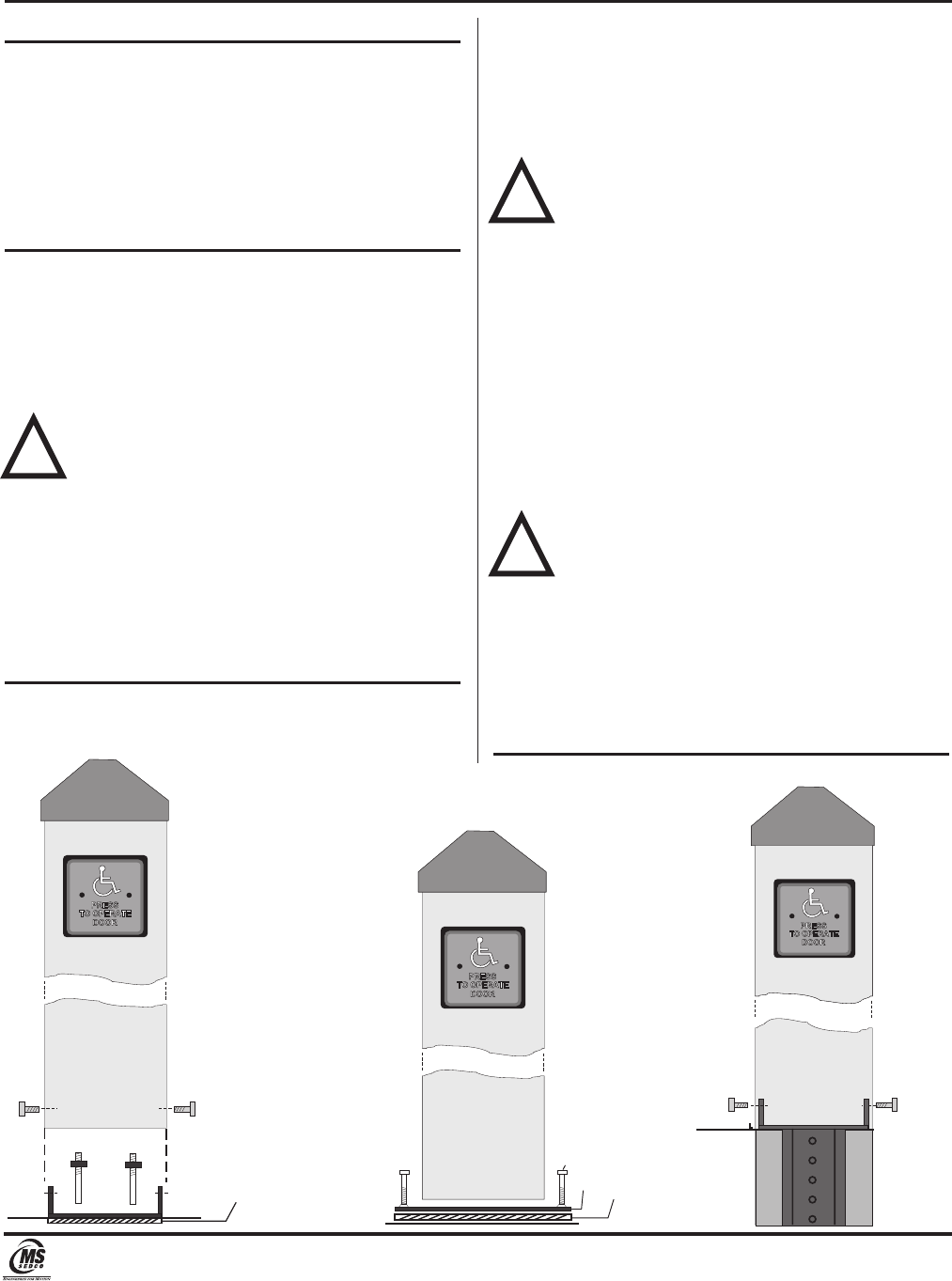
SURFACE MOUNT INSTALLATION WITH INTERNAL SHOE
(see Figure 1a)
1) Drill concrete for two 3/8" x 3" anchor bolts provided
using the mounting shoe as a template.
2) Place plastic rust shield provided over holes in the
concrete, set mounting shoe onto the rust shield.
NOTE: If bollard switch is to be hardwired, pull
conduit through holes in the center of the rust
shield and mounting shoe. Pull electrical wires
long enough to be accessible from the top of the
bollard once mounted (approximately 42”).
3) Hammer anchor bolts into holes in concrete
shimming as necessary to level bollard. Securely
tighten anchor bolts.
4) Slide bollard over mounting shoe and secure with the
four 1/4"-20 x 1/2" bolts provided. Caulk around
base of bollard as needed.
PROCEED TO SECTION 3-WIRING
SURFACE MOUNT INSTALLATION WITH EXTERNAL SHOE
(see Figure 1b)
1) Drill concrete for four 5/16” x 2 1/2” power bolts
provided using the mounting shoe as a template.
2) Place plastic rust shield provided over holes in the
concrete, set bollard onto the rust shield.
NOTE: If bollard switch is to be hardwired, pull
conduit through holes in the center of the rust
shield and mounting shoe. Pull electrical wires
to top of bollard so they are accessible.
3) Hammer power bolts into holes in concrete
shimming as necessary to level bollard. Securely
tighten power bolts.
4) Caulk around base of bollard as needed.
PROCEED TO SECTION 3-WIRING
IN-GROUND MOUNT INSTALLATION (see Figure 1c)
1) Core a 3” diameter hole in the concrete 12” deep. If
no concrete exists, dig a hole 12” deep.
2) Secure the in-ground mounting shoe to the bollard
with the four 1/4-20 x 1/2" bolts provided.
3) Place the entire bollard assembly into prepared hole.
NOTE: If bollard switch is to be hardwired, pull
conduit through hole in the center of the
mounting shoe. Pull electrical wires to top of
bollard so they are accessible.
4) Pour concrete into hole.
5) Push bollard further into the hole until base is at
proper height.
6) Level and brace bollard.
7) Once all concrete has cured, caulk around base of
bollard as needed.
PROCEED TO SECTION 3-WIRING
!
!
!
5"
GROUND LEVE L
1/4-20 x 1/2” Bolt
MOUNTING
SURFACE
RUST SHIELD
3/8" x 3" ANCHOR
BOL TS & BRACKET
1/4-20 x 1/2” Bolt
MOUNTING
SURFACE
RUST SHIELD
5/16” x 2 1/2”
Power Bolts
9“ SQUARE
WELDED FOOT
FIGURE 1c
7898 Zionsville Road Indianapolis, Indiana 46268
Telephone: (317) 842-2545 www.mssedco.com custsvc@mssedco.com
608 Series
Heavy Duty Switch Bollard INSTALLATION INSTRUCTIONS
Page 2
(/MANU) 608v1017
Section 3
Wiring
HARDWIRED
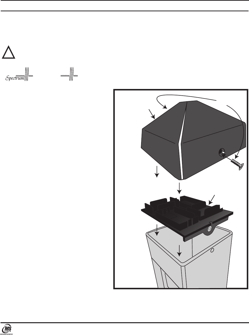
1) Connect the two signal wires to the appropriate contacts on the switch. (Standard connections are COM and N.O.)
2) Set the cap platform (provided) in the top of the switch bollard aligned with the mounting holes.
3) Install the cap and fasten with the two 1/4-20 screws provided.
NOTE: Two signal wires are required per switch on vestibule models.
RADIO CONTROL (WIRELESS)
When one of the ClearPath Transmitter or ClearPath
Spectrum Transceiver options are ordered from the
factory, the 608 Bollard will come complete with all
the necessary Transmitter/Transceiver components
installed in the integrated Cap assembly that
attaches to it and programming instructions. The
ClearPath Receiver (CP/RX) or ClearPath Spectrum
Coordinator (S-COR) must be ordered separately.
!
hClearPat
™
CAP
Transmitter/Transceiver
Housing
1/4-20
Screw
hClearPat
™
7898 Zionsville Road Indianapolis, Indiana 46268
Telephone: (317) 842-2545 www.mssedco.com custsvc@mssedco.com
