MSA Innovation 10058539 RFID Tag Writer User Manual 10024089 10 22
Mine Safety Appliances Company RFID Tag Writer 10024089 10 22
User Manual
TAL 507 (L) Rev. 0 © MSA 2005 Prnt. Spec. 10000005389(A) Mat. 10067066
Doc. 10067066
The warranties made by MSA with respect to the product are voided if the product is
not used and maintained in accordance with the instructions in this manual. Please
protect yourself and your employees by following the instructions. Please read and
observe the WARNINGS and CAUTIONS inside. For any additional information relative
to use or repair, write or call 1-800-MSA-2222 during regular working hours.
This device complies with Part15 of the FCC Rules. Operation is subject to the follow-
ing two conditions; (1) this device may not cause harmful interference, and (2) this
device must accept any interference received, including interference that may cause
undesired operation. Changes or modifications not expressly approved by the manu-
facture could void the user's authority to operate the equipment.
NOTE: This equipment has been tested and found to comply with the limits for a Class
Adigital device, pursuant to Part 15 of the FCC Rules. These limits are designed to pro-
vide reasonable protection against harmful interference when the equipment is oper-
ated in a commercial environment. This equipment generates, uses, and can radiate
radio frequency energy and, if not installed and used in accordance with the instruc-
tion manual, may cause harmful interference to radio communications. Operation of
this equipment in a residential area is likely to cause harmful interference in which case
the user will be required to correct the interference at his own expense.
THIS MANUAL MUST BE CAREFULLY READ AND FOLLOWED BY ALL PERSONS WHO
HAVE, OR WILL HAVE, THE RESPONSIBILITY FOR UPGRADING THE AIR MASK. This
Air Mask will performas designed only if upgrading according to the Instructions.
OTHERWISE IT COULD FAIL TO PERFORM AS DESIGNED, AND PERSONS WHO RELY
ON THE AIR MASK COULD SUSTAIN SERIOUS PERSONAL INJURY OR DEATH.
SOFTWARE INSTRUCTIONS
ICM®Tx Unit Data
Program
ICM TX
CONTENTS
CD Rom
ICM Tx Reader / ID Tag Writer
User’s Instructions
USB cable
System Requirements
Operating System: Windows 98 or higher
PC requirements: 200 Mhz CPU, 64 MB RAM, 50 MB
Free HardDisk Space, USB 1.1 port.
This PC software for the ICM was prepared and tested
carefully and conscientiously. Because of the great
variety of hardware and software that exists, it is not
possible to check all applications. Therefore the use of
the CD-ROM on a PC workplace or in a network shall
take place solely at the user’s risk. MSA shall assume
no guarantee or liability whatsoever for the use of the
softwareon a PC workplace or for implementation
and use in a network or any direct, indirect or remote
consequential damage arising from this.
1. Connect the ICM Tx Reader/ ID Tag Writer to an avail-
able USB porton the PC.
2. Insert CD-ROM into computer. An instructions screen
will automatically appear. Follow instructions on
screen.
ID Tag
The ID Tag (P/N10058545) is not provided as a part of the
ICM Tx Reader / ID Tag Writer Kit.
The purpose of the ID Tag is to associate a user ID or
jump seat location with the ICM Tx Unit. Once the ICM
Tx Unit has read the ID data from a tag, that ID will remain
associated with the ICM Tx Unit until another ID Tag has
been read or enough time has elapsed.
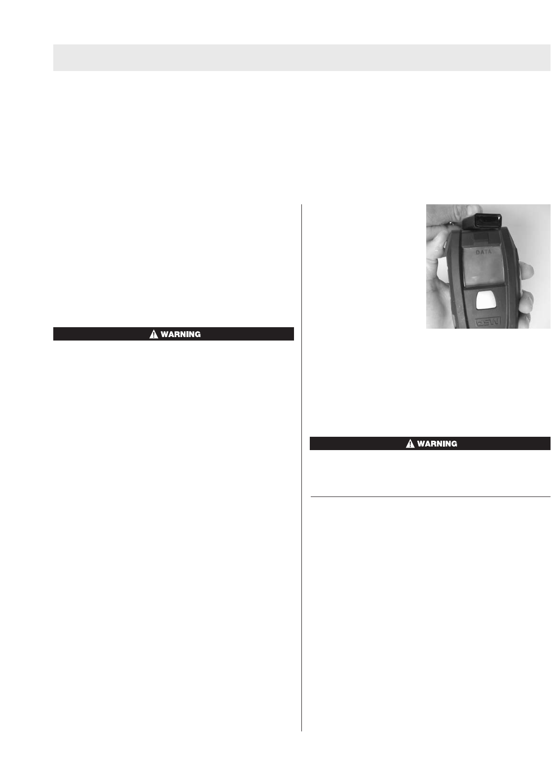
Prior to pressurization of
the SCBA and during
inspection, the user can
“tag in” by depressing and
holding the top mode but-
ton (green) until the word
“DATA” appears in the dis-
play. While “data” is dis-
played, position the ID tag
as shown in the picture
below.The ICM will sound
asingle beep confirming
that the ID data has been read.
Correct ID Tag orientation.
The ID Tag has a space for the user to place a label in
which the ID information can be written on the outside of
the ID Tag for easy identification. This space is located
on the side of the ID Tag opposite the approval label.
Tomaintain the ID Tag’sIntrinsic Safety Approval, any
label that the user attaches to the ID tag must be less
than 4 squarecentimeters in total area.
FIRST SCREEN – ICM TX READER / ID TAG WRITER
Note: The ICM Tx Reader/ ID Tag Writer must be con-
nected and recognized by the PC beforestarting ICM
software program. A green LED should light on the ICM
Tx Reader / ID tag writer box.
1. Two icons will appear, one showing the ICM Tx Unit
and one showing the ID Tag. This softwareallows for
downloading of the ICM Tx Unit or storing ID informa-
tion on the ID Tag.
2. Choose the desired function by clicking on the appro-
priate picture.
Note: This selection can also be made by clicking “File”
and then selecting either “ICM Link” or “Tag Writer”.
3. Refer to the appropriate section below for further
details and instructions.
2
TAL 507 (L) Rev. 0 - 10067066
TABLE OF CONTENTS
Contents..................................................................................................................................................................................2
First Screen .............................................................................................................................................................................2
ICM Link ..................................................................................................................................................................................3
ID Tag Writer............................................................................................................................................................................4
ICM TX
ICM LINK
Reading ICM settings
1. To retrieve the ICM’s settings (serial ID, date, time,
duration of ID tag memory, and time remaining calcu-
lation setpoint), first press and hold the mode button
(green) on ICM until the “data” appears on the LCD
screen.
2. Quickly align ICM with ICM Tx Reader/ ID Tag Writer
as shown on the label.
3. Click “read settings”. (If the “read settings” button
appears grey and inactive, be sure that the ICM Tx
Reader / ID Tag Writer is properly connected and rec-
ognized by the computer)
4. The data should appear on the screen within a few
seconds. An amber LED will light on the ICM Tx
Reader/ ID Tag Writer while information is being trans-
ferred from the ICM.
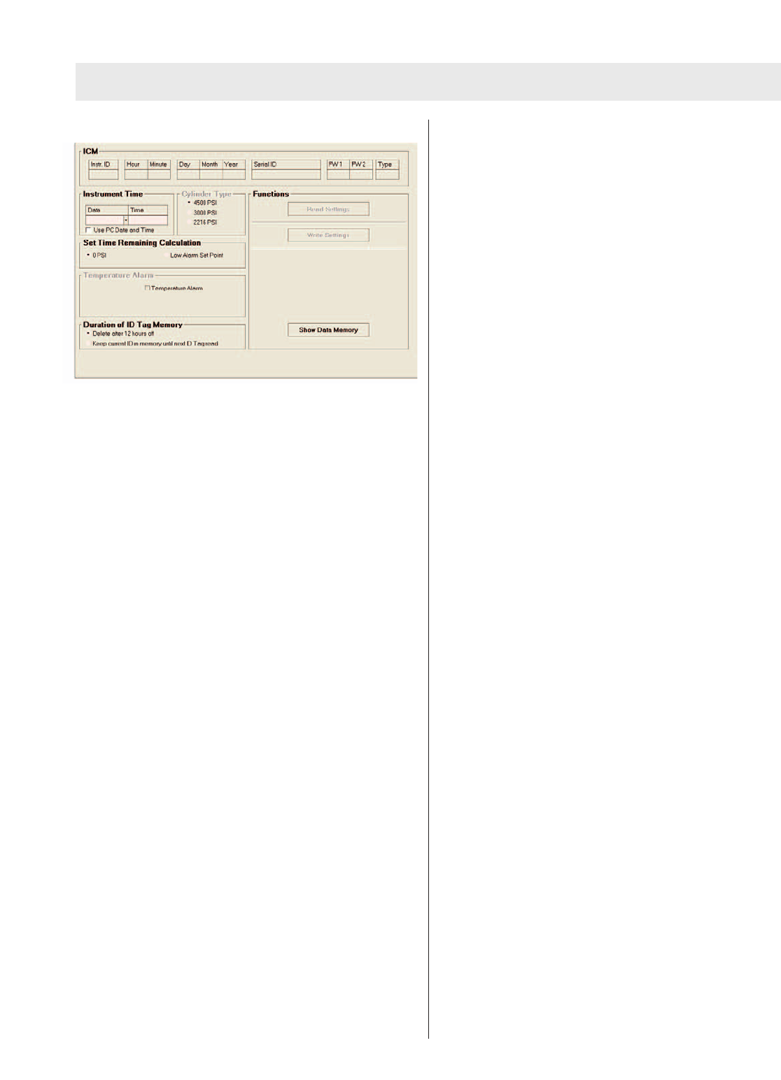
Changing ICM settings
1. The instrument time and date can be reset or edited
by entering the desired date in time in the fields
labeled “Date” and “Time”.
Note: By default, the ICM Tx Unit internal clock is set to
Eastern Standard Time. The ICM Tx Unit contains an
internal battery used to maintain the time on the clock
when the AA batteries arenot installed. The clock should
maintain it’s time keeping ability when the AA batteries are
not installed.
2. By clicking “Use PC Date and Time” the PC clock
time and date will be used to set the ICM clock.
3. The ICM Tx Unit can be set to give the time remaining
display in 2 modes. It counts down to 0 psi cylinder
pressure (default) or it can be set to count down to the
low pressurealarmpoint. This mode can be toggled
by selecting either “0 PSI” or “Low Alarm Set Point”.
4. Under the heading “Duration of ID Tag Memory”, there
are2options: “Delete after 12 hours off” (default) and
“Keep current ID in memory until next ID tag read”.
“Delete after 12 hours off” means that the ICM will
only retain the last read ID tag data for 12 hours after
the ICM Tx Unit has been turned off (sleep mode).
After 12 hours, the ICM Tx Unit will default back to the
serial number. “Keep current ID in memory until next
ID tag read” means that the ICM Tx Unit will retain the
last read ID tag information until another ID tag has
been read into the ICM Tx Unit.
Writing ICM settings
Note: The ICM Tx Unit data must be read before settings
can be written to the unit. After making all settings
changes on the screen, the changes must then be written
to the ICM Tx Unit.
1. To write changes made, press and hold the mode but-
ton (green) until “DATA” is displayed on the LCD
screen.
2. Quickly align ICM Tx Unit with ICM Tx Reader/ ID Tag
Writer as shown on the label.
3. Click “write settings”. (If the “write settings” button
appears grey and inactive, be sure that the ICM Tx
Reader / ID Tag Writer is properly connected and rec-
ognized by the computer)
4. The data should be written within a few seconds. An
amber LED will light on the ICM Tx Reader/ ID Tag
Writer while information is being transferred to the
ICM Tx Unit.
Todisplay ICM data log
1. To display the data log memory of the ICM Tx Unit,
press and hold the mode button (green) until “data” is
displayed on the LCD screen.
2. Quickly align ICM with ICM Tx Reader/ ID Tag Writer
as shown on the label.
3. Click “Show Data Memory”.
4. A dialog box will appear asking “Load New Data?”.
Click “Yes” to proceed with downloading the data log
from the ICM Tx Unit. (By clicking “No”, you can
search for previously downloaded data log files and
review them.)
Note: To review previously downloaded data log files,
steps 1 and 2 of this section may be skipped.
5. After clicking “Yes” the data will begin downloading.
This may take up to 2 minutes to complete the data
transfer.An amber LED will light on the ICM Tx
Reader/ ID Tag Writer while information is being trans-
ferred from the ICM Tx Unit.
6. When the data transfer is complete, a new window
should appear displaying session information.
3TAL 507 (L) Rev. 0 - 10067066
ICM TX
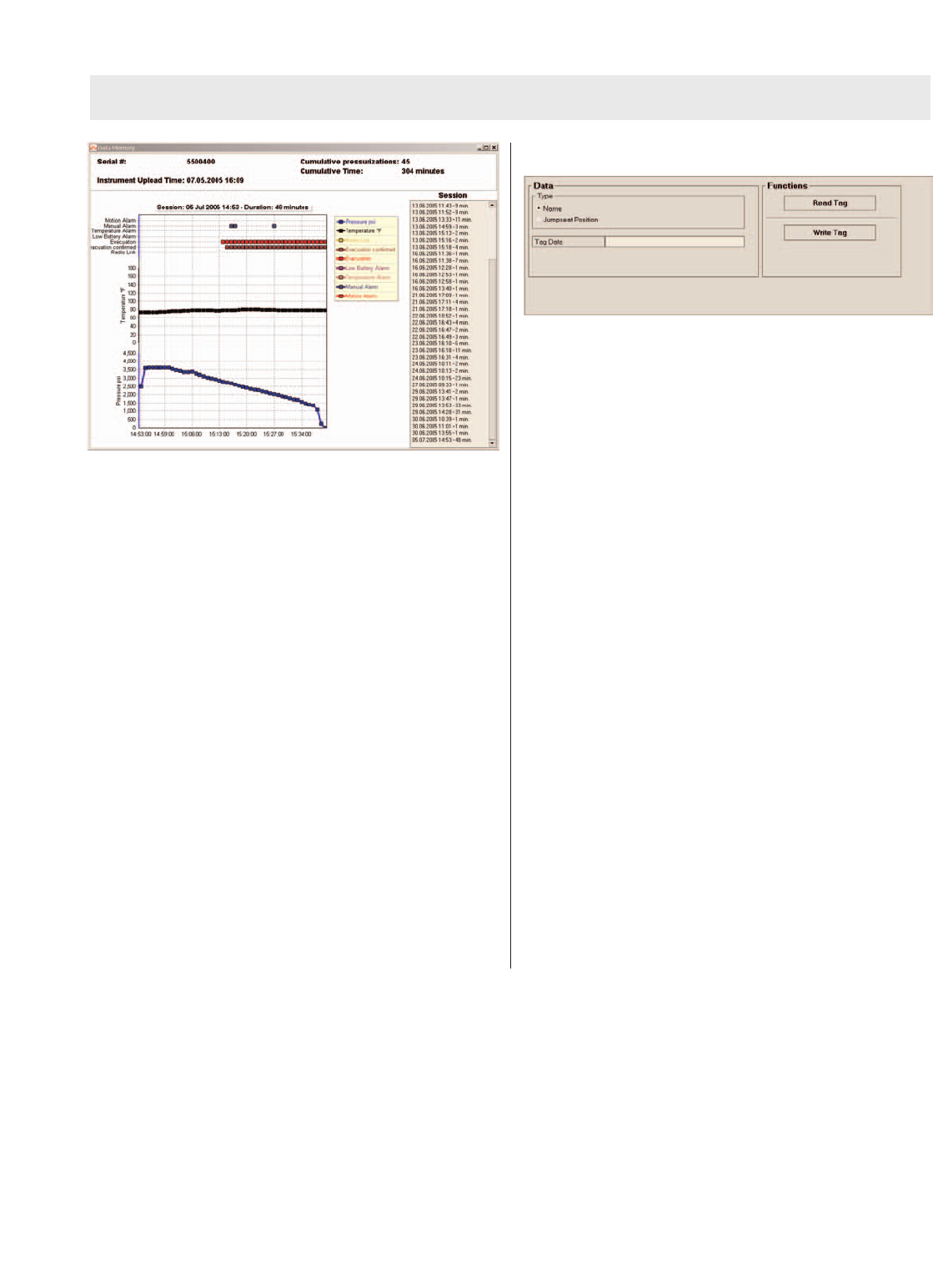
Navigating the Data Memory Window
1. The session displayed can be selected by clicking the
date and time of the desired session listed on the right
side of the screen under the heading “Session”. A
session begins everytime the ICM is powered on and
ends when it is turned off.
2. The top portion of the graph shows ICM functions that
activated during the session currently displayed.
3. The center black line portion of the graph shows the
temperature that the ICM Tx unit was reading. This is
only applicable if the ICM Tx Unit has the temperature
alarm function.
4. The bottom blue line portion of the graph shows the
pressure as read by the ICM.
5. The graph can be panned from left to right by placing
the cursor on the graph and holding the right mouse
button and dragging from side to side.
6. The graph can be zoomed in by placing the cursor at
the desired zoom location on the graph and holding
the left mouse button and simultaneously moving the
cursor at a 45 degree angle to the right of the cursor
position.
7. The graph can be zoomed out by placing the cursor at
the desired zoom location on the graph and holding
the left mouse button and simultaneously moving the
cursor at a 45 degree angle to the left of the cursor
position.
ID TAG WRITER
Writing information to the ID Tag
1. While in the ID tag writer portion of the program, first
select the type of ID information to be entered by
clicking either “Name” or “Jumpseat Position”.
2. Next, enter up to 30 characters of ID information in
the entry box titled “Tag Data”.
3. Insert the ID tag into the port in the front of the ICM
Tx Reader/ ID Tag Writer. The tag should be inserted
unit it bottoms out.
4. Click “Write Tag”.
Reading information stored in the ID Tag
1. Insert the ID tag into the port in the front of the ICM
Tx Reader/ ID Tag Writer. The tag should be inserted
unit it bottoms out.
2. Click “Read Tag”
3. After a few seconds, the stored data should appear in
the box titled “Tag Data”. If no ID information has
been written to the ID Tag, nothing will be displayed in
the Tag Data box.
4
TAL 507 (L) Rev. 0 - 10067066