MSA Innovation 10058545 RFID Tag User Manual
Mine Safety Appliances Company RFID Tag
User Manual
TAL 507 (L) Rev. 1 © MSA 2005 Prnt. Spec. 10000005389(A) Mat. 10058881
Doc. 10000020525
Use of this device must be consistent with the requirements of NFPA 1500 Fire Department Occupational Safety
and Health Programs.
The Nightfighter Heads-Up Display System is NIOSH and NFPAcertified as an accessory for the Ultra Elite
Facepiece for use with the MSA MMR, Firehawk MMR, and BMR breathing apparatus only.
The warranties made by MSA with respect to the product are voided if the product is not installed, used and ser-
viced in accordance with the instructions in this manual. Please protect yourself and your employees by following
the instructions. Please read and observe the WARNINGS and CAUTIONS inside. For any additional information
relative to use or repair,write or call 1-800-MSA-2222 during regular working hours.
Read this manual carefully if you have or will have the responsibility for using or servicing the product. These
instructions pertain only to the use of the version of the ICM Tx Unit and NightFighter Heads-up display System
which integrates with the SCBA. These instructions, in addition to the instructions supplied with the SCBA, must
be carefully read and followed by all persons who use or maintain this product. This includes those who have
any responsibility involving its selection or application. The ICM Tx Unit and NightFighter from MSA will per-
formas designed only if used and maintained according to the instructions. Otherwise it could fail to perform
as designed and persons who rely on the SCBA could sustain serious personal injury or death.
WARNING
ICM®Tx Unit
NightFighter®
Heads-Up Display
System
NOTICE
These instructions must remain attached to the ICM Tx Unit or NightFighter Heads-up display system. The end
user only is authorized to remove them from the device. – NFPA1982 (1998 Edition), par 3.2.3
OPERATION AND MAINTENANCE INSTRUCTIONS
The NightFighter Heads-Up Display System and ICM Tx Unit comply with Part 15 of the FCC Rules. Operation is
subject to the following conditions:
(1) This device may not cause harmful interference and (2) This device must accept any interference that may
cause undesired operation.
Changes and modifications not expressly approved by the manufacturer could void the user’s authority to oper-
ate the equipment.

NIOSH APPROVAL INFORMATION
CAUTIONS AND LIMITATIONS
I - Contains electrical parts which have not been evaluat-
ed as an ignition source in flammable or explosive
atmospheres by MSHA/NIOSH.
N - Never substitute, modify, add, or omit parts. Use only
exact replacement parts in the configuration as speci-
fied by the manufacturer.
S- Special or critical User's Instructions and/or specific
use limitations apply. Refer to User's Instructions
before donning.
Note: See NIOSH Approval Label, Inserted in the Users
Instructions for complete list of CAUTIONS and LIMITA-
TIONS for the Respirator.
S-SPECIAL OR CRITICAL USER'S INSTRUCTIONS
1. Misuse or abuse of the NightFighter Heads-Up Display
System, the ICM Tx Unit, or the equipment to which
they areattached, or using this equipment in a manner
or situation not intended by the manufacturers, may
result in damage to the equipment or may result in
personal injuryor death to user or persons dependent
on the user.
2. Always inspect the NightFighter Heads-Up Display
System and ICM Tx Unit for damage beforeuse. If
damage is found, immediately remove the device from
service.
3. When NightFighter Heads-Up Display System is used
as a gauge (Not in conjunction with standard pneu-
matic gauge) continuous operation mode must be
used to maintain NIOSH approval.
4. Do not alter these components. Altering will void the
Intrinsic-Safety rating and may affect the Intrinsic-
Safety of the device.
Note: The NightFighter Heads-Up Display System
Receiver is for use with an Ultra Elite®Facepiece only. It
cannot be used without the proper installation of the
Receiver, Facepiece Bracket and either NightFighter
Transmitter or ICM Tx Unit from MSA.
5. The NightFighter Heads-Up Display System allows a
user to clearly and easily see air cylinder content while
wearing an SCBA equipped with the Ultra Elite
Facepiece.
Note: The NightFighter Heads-Up Display can only be
used with an Ultra Elite Facepiece.
6. The NightFighter Heads-Up Display consists of three
(3) separate assemblies:
• Bracket assembly attached to an Ultra Elite
Facepiece.
• Receiver mounted on the bracket assembly.
• ICM Tx Unit or Transmitter assembled to the gauge
line. (See Installation Instruction P/N 10035581,
transmitter only).
7. The NightFighter Heads-Up Display System's Receiver
shows the user the air cylinder content in one quarter
cylinder increments, from a full cylinder to an empty
cylinder, by an LED light pattern.
8. The NightFighter Heads-Up Display System's
Transmitter is assembled to the gauge line hose. (The
ICM Tx Unit serves as the transmitter). The transmit-
ter sends a signal to the receiver (on the facepiece) of
the air cylinder content.
9. The NightFighter Heads-Up Display System's Receiver
has seven (7) LEDs that are used to form light pat-
terns.
10. The NightFighter Heads-Up Display System's
Receiver has a photo sensor for the LED lights to
automatically adjust the brightness of the LED based
on to the brightness as measured outside of the face-
piece.
11. The NightFighter Heads-Up Display System's
Receiver will indicate a low batteryby a Yellow LED
light for the receiver, ICM Tx Unit, or NightFighter
Transmitter.
The NightFighter Heads-Up Display System operates
using (4) standardAA alkaline batteries in the ICM Tx and
(2) standardAA alkaline batteries in the receiver.When
using a Nightfighter Heads-Up Display System with stan-
dard Transmitter (2) AAA alkaline batteries are needed.
The NightFighter Heads-Up Display System notifies the
user when the batteries need to be replaced.
Use only Duracell MN2400, Energizer E92, or Eveready
A92 AAA alkaline batteries in the TRANSMITTER. Use
of other batteries, or a combination of batteries from
different manufacturers, will affect the performance of
the unit and will void the Intrinsic Safety Approval.
TABLE OF CONTENTS
Description ..............................................................................................................................................................................2
System Operations..................................................................................................................................................................5
Using the ICM Tx Unit.............................................................................................................................................................9
During Use.............................................................................................................................................................................13
Cleaning and Maintenance ...................................................................................................................................................15
Quick-Fill®System Operation................................................................................................................................................17
URC Assembly Operation .....................................................................................................................................................21
Warranty ................................................................................................................................................................................24
DESCRIPTION
2
TAL 507 (L) Rev. 1 - 10058881

Use only Duracell MN1500 or Energizer E91 AA alka-
line batteries in the RECEIVER and ICM Tx. Use of
other batteries, or a combination of batteries from dif-
ferent manufacturers, will affect the performance of
the unit and will void the Intrinsic Safety Approval.
Intrinsically-Safe Rating
The NightFighter Heads-Up Display System and ICM Tx
Unit is certified Intrinsically-Safe in the United States for
use in Class 1, Div. 1, Groups A, B, C, D, and hazardous
locations, Temperature T1.
Note: The intrinsically-safe level of any system which
uses the NightFighter Heads-Up Display System or ICM
Tx Unit is that of the lowest intrinsically-safe rating of any
single component in the system.
DESCRIPTION
3TAL 507 (L) Rev. 1 - 10058881

4
TAL 507 (L) Rev. 1 - 10058881
NOTES
SYSTEM OPERATIONS
NIGHTFIGHTER HEADS-UP DISPLAY SYSTEM FUNC-
TIONALITY
• The NightFighter Heads-Up Display System allows a
user to clearly and easily see air cylinder pressure
while wearing an SCBA equipped with the
NightFighter Receiver and ICM Tx Unit or Nightfighter
transmitter, and the Ultra Elite Facepiece.
•The NightFighter Heads-Up Display System Receiver
is also a multi-mode, battery-powered, low-pressure
warning device which gives visible warning that air
cylinder pressure has reached approximately 25% of
rated cylinder pressure remaining. The receiver will
display one flashing red LED when this point has been
reached.
• The NightFighter Heads-Up Display System Receiver
has a photo sensor for the LED lights to automatically
adjust the brightness of the LEDs based on the light
level outside of the facepiece.
• The NightFighter Heads-Up Display System Receiver will
indicate a low battery by a flashing yellow LED light
for the receiver and ICM Tx Unit or Transmitter.See
the During Use section for Low Battery Warnings.
• The NightFighter Heads-Up Display System Receiver
operates using two standard AA alkaline batteries and
notifies the user when the batteries need to be
replaced.
Nightfighter Heads-UP Display System Receiver
Display:
•The ICM Tx Unit or Nightfighter transmitter sends a
signal to the NightFighter receiver (on the facepiece),
which displays the air cylinder pressurein one quarter
cylinder increments, by an LED light pattern. See
chart 1.
Assembly of Receiver to Facepiece Bracket
With the facepiece laying on its side:
1.Turn receiver so the thumbscrew is at the bottom of
receiver and MSA logo of the receiver is to the right.
2.Align the receiver's two slots with the bracket's guide
rails.
3. Slide receiver's slots onto bracket guide rail.
Thumbscrew of receiver should align with thumbscrew
hole in bracket.
4. Thread thumbscrew into bracket finger-tight.
Functional Tests
Always test the NightFighter Heads-Up Display
System Receiver and ICM Tx Unit to be sure the sys-
tem operates properly beforeentering any hazardous
atmosphere. Do NOT use this device unless it passes
all inspection and functional tests. Failure to follow
this warning can result in serious personal injury or
death.
NightFighter Receiver and ICM Tx Unit or Transmitter
must be within approximately 12 to 15 inches of each
other for the Receiver's LED lights to work properly.
5TAL 507 (L) Rev. 1 - 10058881
R
GG
G
Y
G
G
G
G
Y
76% to 100%
Full Cylinder, 4 Green LED
20 Sec. Steadily ON
75% to 51%
3/4 Full Cylinder, 3 Green LED
20 Sec. Steadily ON
26.1% to 50%
1/2 Full Cylinder, 2 Yellow LED
30 Sec. Flashing ON/OFF
25% to 0%
1/4 Full Cylinder, 1 Red LED
Flashing Continuously
Yellow Light
Low Battery LED for
Receiver/Transmitter
Orange Light
Pre-Alarm for
ICM Tx Unit
Y
O
NOT USED
Chart 1: NightFighter Heads-Up Display System Receiver Cylinder Pressure LED Pattern
CAUTION

6
TAL 507 (L) Rev. 1 - 10058881
NOTES

ICM TX UNIT FUNCTIONALITY
• The ICM Tx Unit is assembled to the gauge line hose
and serves as the transmitter for the NightFighter
Heads-Up Display System.
• The ICM Tx Unit turns on automatically when the user
opens the SCBA cylinder valve. As the pressure
reaches approximately 200 psig, both visible and
audible alarms activate automatically, indicating that
the unit is functional. When the system is pressurized
above 25% of the rated service pressure, the alarm
enters the Monitor (normal) Mode. The unit remains in
Monitor mode until the user shuts off the cylinder air
and presses the reset button twice in quick succes-
sion.
• If the user is motionless for approximately 20 seconds,
the ICM Tx Unit enters pre-alarm. During pre-alarm,
the device sounds 3 progressively louder tones and
the RED LED on the ICM Tx Unit flashes slowly. Also,
during pre-alarm, an ORANGE LED will be displayed
in the Nightfighter Receiver. Movement of the unit
cancels the pre-alarm.
• If the user remains motionless for 30 seconds
(approx.), the ICM Tx Unit enters full alarm. During full
alarm, the PASS repeatedly sounds two high-pitched
tones followed by a buzz. During full alarm the RED
LED on the ICM Tx Unit also flashes rapidly.
• The ICM Tx Unit can be set into full alarm at any time
(even without air pressure) by pressing the opaque
alarm button.
• The ICM Tx Unit has three control buttons.
o The RESET/OFF (yellow) button resets the device
from the full alarmmode. It also shuts the unit off
after the cylinder valve is closed and all air pressure
is bled from the unit.
o The center opaque lighted alarm button (green/red)
activates the full alarm mode with or without air
pressure.
o The top mode button (green) will refresh the receiver
display, set the receiver to continuous mode, and
change the ICM Tx Unit digital display mode
between pressure remaining and calculated service
life remaining. When the ICM Tx Unit is OFF, the
mode button (green) can be used to scan an ID Tag
into the ICM Tx Unit. See the “Using the ICM Tx
Unit” section for details.
•The PASS function uses RED and GREEN light-emit-
ting diodes (LEDs) behind the opaque alarm button to
display its status visually:
o GREEN LEDs start to flash when the cylinder valve
is opened and shows that the device is operational.
o RED LEDs flash slowly when the device is in pre-
alarm and flash rapidly when the device is in full
alarm.
• The ICM Tx Unit operates using four standard AA
alkaline batteries and notifies the user when the bat-
teries need to be replaced by emitting an audible beep
(1 beep every 5 seconds), displaying and empty bat-
tery icon on the LCD screen, and by flashing a YEL-
LOW LED on the Nightfighter Receiver Display.
• The ICM Tx Unit has a data logging feature that
records information about the SCBA while the ICM Tx
Unit is turned on. This data log memory can be
accessed using the ICM Tx Reader / ID Tag Writer
interface.
• The ICM Tx Unit contains an internal real time clock.
This clock can be reset using the ICM Tx Reader / ID
Tag Writer interface. By default, the internal clock is
set to EasternStandard Time.
7TAL 507 (L) Rev. 1 - 10058881

8
TAL 507 (L) Rev. 1 - 10058881
NOTES

Note: Refer to chart 2 for the various audible and visual
indicators.
ICM TX UNIT THERMAL ALARM (THERMISTOR)
DEVICE TECHNICAL SPECIFICATIONS
Although this thermal alarm provides an indication
that the time-temperature curve is exceeded, the
curve may not represent the threshold to injury due to
variations in individuals and the protective clothing
worn. Use this alarm as a reference only to increasing
time-temperature. Do not use as a substitute for stan-
dard operating procedures regarding escape from
time-temperature extremes. Failure to do so can result
in serious personal injury or death.
The ICM Tx Unit can monitor temperature conditions if the
Thermal Alarm option is purchased. If the wearer is
exposed to more than a pre-set limit of time/temperature,
the unit will sound a tone every 3 seconds.
USING THE ICM TX UNIT
9TAL 507 (L) Rev. 1 - 10058881
WARNING
AUDIBLE INDICATOR
ACTION VISIBLE INDICATOR
without Thermistor with Thermistor (ICM)
Automatic Activation (with air cylinder pres-
sureapplied)
Manual Activation
Sensor Mode (with or without Pressure)
PreAlarm
(with or
without
Pressure
Full Alarm(with or without Pressure)
Deactivation
of Full Alarm
Deactivation of PreAlarm (with Shake
or move Unit)
Low Battery
Thermal Alarm Activation (see Thermal
Alarm Activation Curve)
Single Rising Tone
with Bee-Bop
Startup - Single Rising
Tone with Bee-Bop
(also Full Alarm)
none
Low Volume Rising
Tone
Medium Volume Buzz
High Volume Rise Tone
Followed by Buzz
Two High Volume
Tones Followed by
Buzz
Bee
Bee-Bop-Bop
none
1Beep every5sec-
onds
N/A
Single Rising Tone
with Bee-Bop
Startup - Single
Rising Tone with Bee-
Bop (also Full Alarm)
none
Low Volume Rising
Tone
Medium Volume Buzz
High Volume Rise
Tone Followed by
Buzz
Two High Volume
Tones Followed by
Buzz
Bee
Bee-Bop-Bop
none
1Beep every5sec-
onds
1Beep every 3 sec-
onds
GREEN/RED Light
Flash Front Panel
GREEN/RED Lights
Flash Front Panel -
Red Light Flashing
GREEN Light
Flashes
RED Light Flashes
RED Light Flashes
RED Light Flashes
GREEN Light
Flashes
GREEN Light
Flashes
none
none
First 4 seconds (approx.)
Second 4 seconds (approx.)
Last 4 seconds (approx.)
1st push of rest button
2nd push of reset button
Chart 2: Audible/Visible Indicators
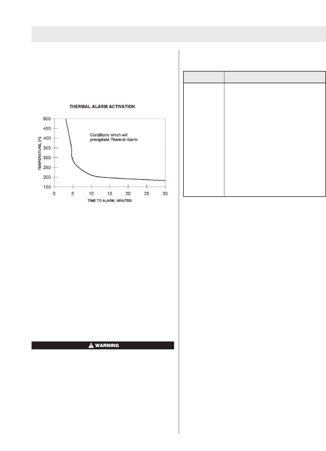
Chart 3 shows the ICM Tx Unit thermal alarm activation
curve. The time/temperature limits are based on the
curve. The thermal alarm sounds if the pre-set limit
exceeds the curve. The alarm will self-cancel depending
on the severity of conditions. This may occur even though
the temperature is above the thermal curve.
Chart 3: ICM Tx Unit Thermal Alarm Activation Curve
Note: This chart was generated from data obtained in a
laboratorysetting and is for reference only. Conditions
are highly variable in an actual use scenario. Users of the
ICM Tx Unit with the thermal alarmoption should develop
procedures for the use of this feature.
Optional ID Tag (PN 10058545), for use with ICM Tx
Unit
The purpose of the ID Tag is to associate a user ID or
jump seat location with the ICM Tx Unit. Once the ICM
Tx Unit has read the ID data from a tag, that ID will remain
associated with all future sessions of the ICM Tx Unit until
another ID Tag has been swiped.
The ID Tag has a space for the user to place a label in
which the ID information can be written on the outside of
the ID Tag for easy identification. This space is located
on the side of the ID Tag opposite the approval label.
Any label attached to the ID tag must be less than 4
squarecentimeters in total area, otherwise the intrin-
sic safety approval is void.
Before using the ID tag, inspect for damage or cracks
in the case. If damage is found, discardand replace
the ID tag.
Failureto follow these warnings can result in serious
personal injury or death.
SPECIFICATIONS
Chart 4 shows the specifications for the ICM Tx Unit.
Chart 4: ICM Tx Unit Specifications
Functional Check of the ICM Tx Unit
1. Don the SCBA following the instructions in the SCBA
User’sInstruction Manual.
2. When opening the cylinder valve to perform the SCBA
“system checks,” listen for the ICM Tx Unit automatic
activation indicator as described in table.
3. Look through the facepiece lens at the LED panel, the
LEDs should illuminate through the startup sequence
as the SCBA is pressurized. The startup sequence is
as follows:
a. Four Green LED’s ON/OFF.
b. Three Green LED’s ON/OFF.
c. Two Yellow LED’s ON/OFF.
d. One Red LED ON/OFF.
e. One Yellow LED ON/OFF.
f. Current cylinder pressure.
4. Look to verify that the GREEN light on the ICM Tx Unit
is slowly flashing.
5. Stand motionless for approximately 20 seconds.
Listen for the pre-alarm to sound the low volume
repeated tones. Look for the RED light on the ICM Tx
Unit to alternately flash slowly.
6. Remain motionless until the full alarmactivates. Listen
for the alarm to sound the increasing loud repeated
tones. Look for the light to flash RED rapidly.
7. Reset the ICM Tx Unit by pushing the RESET button
on the side of the unit 2 times within approximately 1
second.
8. To check manual activation of the full alarm, push and
HOLD the alarmbutton on the front of the unit.
9. Reset the Alarm. Press RESET button 2 times within
approximately 1 second.
USING THE ICM TX UNIT
10
TAL 507 (L) Rev. 1 - 10058881
SPECIFICATIONS
Weight 1.0 pounds (approximately 450 grams
w/battery)
Alarm Output Greater than 95dBA at 3 meters
Battery Four AA Batteries
Battery Life 25 hours in full alarm mode
Electronics Microprocessor controlled
Standards Meets or exceeds NFPA 1982 (1998
Edition)
Listed as intrinsically safe to ANSI UL
913
NIOSH certified for use on MMR SCBA
Not evaluated by MSHA for use in
explosive atmospheres

10. Stand motionless until the pre-alarm sounds. Shake
unit to reset the alarm.
11. If the ICM Tx Unit passes these functional checks,
complete all remaining SCBA donning steps in the
SCBA user’s instruction manual.
12. Disconnect the second stage regulator from the face-
piece.
13. Close the cylinder valve fully.
14. At the appropriate pressure, the NightFighter Receiver
should display one blinking red LED and the Audi-
Larm should sound. Crack the bypass valve slowly to
bleed off pressure until the ICM Tx Unit pressure read-
ing drops below the following values:
a. 530psig - approximately (2216psi system),
b. 750psig - approximately (3000psi System),
c. 1050psig - approximately (4500psi system)
Asingle flashing RED LED should be displayed in the
Nightfighter Heads-Up Display System Receiver at the
appropriate pressure listed above.
15. When the pressure falls below 200psig, turn the ICM
Tx Unit off (Sleep Mode) by pressing the reset button
2times in rapid succession.
USING THE ICM TX UNIT
11 TAL 507 (L) Rev. 1 - 10058881

NOTES
12
TAL 507 (L) Rev. 1 - 10058881
Note: Refer to chart 2 for the various audible and visual
indicators for the ICM Tx Unit.
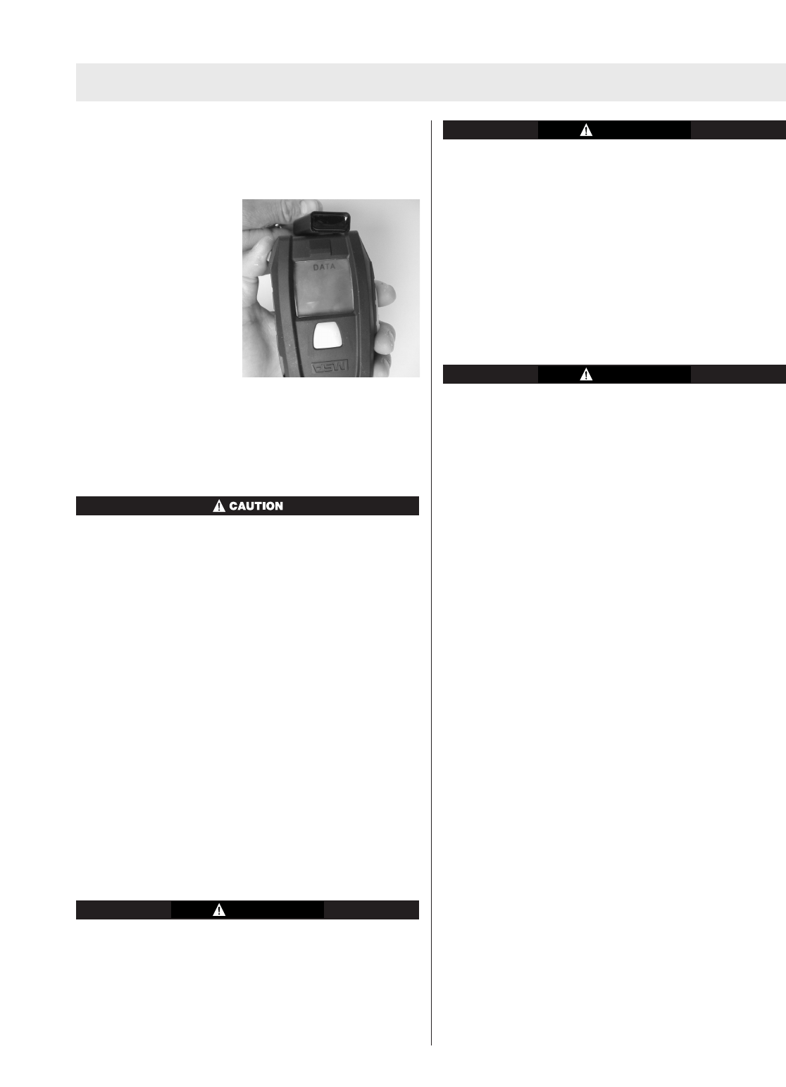
Optional ID Tag (PN 10058545), for use with ICM Tx
Unit
Prior to pressurization of
the SCBA and during
inspection, the user can
“tag in” by depressing and
holding the top mode but-
ton (green) until the word
“data” appears in the dis-
play. While “data” is dis-
played, hold the ID tag as
shown in the picture below.
The ICM will sound a single
beep confirming that the ID
data has been read. If the word “data” disappears before
the ID tag has been read, the ICM Tx Unit has timed out
and the top mode button (green) must be depressed and
held again until “data” reappears.
Correct ID Tag Orientation.
The ID tag is not designed to be taken into a fire. The
ID tag can also be used as accountability tag.
Pressure Display
1. Periodically check the pressureindicated on the ICM
Tx Unit display. It will display either remaining cylinder
pressureor calculated remaining service life.
2. When the pressure reaches 25% of the rated service
pressure, the NightFighter Receiver will display one
flashing RED LED.
3. When the NightFighter Receiver displays one flashing
RED LED, or when the pressure reaches approximate-
ly 25% of the rated service pressure, return to fresh
air.
Changing the ICM Tx Unit Display Mode
1. Press the top mode button (green) once. This will
momentarily refresh the NightFighter Receiver display
as well as light the ICM Tx Unit display.
2. While the ICM Tx Unit display is still lit, press the top
mode button (green) again. This will toggle the display
between remaining cylinder pressure and calculated
remaining service life.
The ICM Tx Unit has the ability to display calculated
remaining service life counting down to 0 psi or 25%
of the rated service pressure. The user must deter-
mine which option has been selected for the ICM Tx
Unit in service. Failure to follow this warning can
result in serious personal injuryor death.
Actual time remaining may be less than the calculated
time displayed. Increases in breathing rate may reduce
remaining time more than expected. Use time indica-
tor as general guide only. The time displayed is based
onthe continuation of the average breathing rate over
the last three minutes. Increases in the breathing rate
after checking the displayed time may result in less
remaining time than anticipated.
Failure to follow this warning can result in serious per-
sonal injury or death.
Starting Continuous Operations Mode
In Continuous Operations Mode, the life of the batter-
ies in the Nightfighter Receiver will be shortened.
Failure to follow this warning can result in serious per-
sonal injury or death.
Note: The Continuous PressureMode can only be activat-
ed when the system is pressurized. Activate the
Continuous PressureMode as follows:
1. Push the top mode button (green) on the ICM Tx Unit
and hold button in for 3 seconds (or push the
Operation Button on the Nightfighter transmitter).
Once LED’slights come on, release button.
2. Receiver will show air cylinder pressure level. LED
lights will stay on to show air cylinder pressure level
drop.
Turning Continuous Operations Mode OFF
Note: The Continuous Operations Mode will deactivate if
low batteryis present.
1. With the ICM Tx Unit in Continuous Operation Mode,
push mode button (green) on the ICM Tx Unit and
hold the button in for 3 seconds (or push the
Operation Button on the Nightfighter transmitter).
Release button once LED lights go off.
2. LEDs will revert to Automatic Mode showing only air
cylinder pressure status at each 25% increment of full
cylinder pressure.
Note: The NightFighter Heads-Up Display System will
automatically turnitself OFF,approximately 60 seconds
after the apparatus is depressurized. (The single red LED
light will flash at this time).
WARNING
DURING USE
13 TAL 507 (L) Rev. 1 - 10058881
WARNING
WARNING

Low Battery Warnings
Replace the batteries in the appropriate device when
the low battery warning sounds. Use only recom-
mended battery types (see Description section of this
manual). Change the battery in non-hazardous area
only. Failure to follow this warning can result in seri-
ous personal injury or death.
Note: There are unique Low Battery Warnings for the
NightFighter Receiver and ICM Tx Unit or Nightfighter
transmitter which are each displayed by the NightFighter
Receiver.
1. If there is a low battery in the receiver, one short
Yellow LED will flash.
2. If there is a low battery in the ICM Tx Unit or
Nightfighter transmitter, double short Yellow LED
flashes will be displayed.
3. If therearelow batteries in the receiver and ICM Tx
Unit or transmitter, the Yellow LED will alternate single
and double flashes.
Replacing the Batteries in the ICM Tx Unit
Do not dispose of the battery in fire. It may explode.
Failureto follow this warning can result in serious per-
sonal injury or death.
1. Loosen the four screws from the battery compartment
of the ICM Tx Unit then remove the battery cover (two
screws if Nightfighter Transmitter is in use).
2. Insert the four AA batteries following diagrams inside
battery compartment (two AAA batteries if Nightfighter
Transmitter is in use). Insert each battery base firmly
into the case, then press down and in on the top of
the battery.
3. Verify that the battery cover gasket is held in place
and is free from damage and debris and is not twisted
in the gasket retention groove in the batterycover.
4. Before replacing the battery cover, be sure that the
rubber cover on the ICM Tx Unit is properly engaged
with the plastic housing. The rubber cover has barbs
that hold it firmly against the plastic housing.
5. Replace the cover.Make certain that the battery
cover is oriented properly. Align the angled tabs near
the battery cover screws with the battery cover.
Check that the rubber cover is no bunched or pinched
under the batterycover,otherwise the batterycover
may not remain water tight.
6. Evenly tighten cover screws by moving in an X pattern
(for ICM Tx Unit) around the cover. Be sure to tighten
the battery cover screws enough to provide adequate
compression on the batterycover gasket to prevent
dirt and moisture from entering the battery compart-
ment. A torque of 6 in lbs is suggested. Do not over-
tighten the screws. Do NOT use a thread sealant on
the screws.
7. Dispose of, or recycle batteries in accordance with all
applicable federal, state, and local regulations.
Replacing the Batteries in the NightFighter Receiver
Do not dispose of the battery in fire. It may explode.
Failure to follow this warning can result in serious per-
sonal injury or death.
1. Loosen the screws to open battery door.
2. Insert two AA batteries (Duracell MN1500 or Energizer
E91) according to the battery orientation noted inside
the compartment. (Older versions of the NightFighter
Receiver use AAA batteries). The approved AAA bat-
tery is Duracell MN2400, Energizer E92, or Eveready
A92.
3. Verify that the batterycover gasket is held in place
and is free from damage and is not twisted in the gas-
ket retention groove in the battery cover.
4. Align the battery cover to the RX housing and tighten
the screws evenly from side to side. Be sure to tight-
en the batterycover screws enough to provide ade-
quate compression on the battery cover gasket to pre-
vent dirtand moisturefrom entering the battery com-
partment. Do not overtighten the screws. Do NOT use
athread sealant on the screws.
5. Dispose of, or recycle batteries in accordance with all
applicable federal, state, and local regulations.
Turning the ICM Tx Unit Off After Doffing the SCBA
Turn off the ICM Tx Unit after doffing the SCBA; other-
wise batteries will be drained. The ICM Tx Unit does
not shut off automatically.
1. Upon returning to fresh air, close the cylinder valve
completely and release all pressurefrom the system
following the SCBA instruction manual.
2. When the pressure falls below 200 psig, turn the
device offby pressing the reset button 2 times in rapid
succession.
3. The ICM Tx Unit will beep 1 time when the button is
pressed once. Pressing the button a second time will
then sound three beeps (“bee-bop-bop”) to indicate
that the unit is turned off. The lights will also stop
flashing.
WARNING
WARNING
DURING USE
14
TAL 507 (L) Rev. 1 - 10058881
WARNING

CLEANING AND DISINFECTING
1. Prepare a cleaning solution by adding Confidence
Plus®Cleaning Solution (P/N 10009971) to water, fol-
lowing the instructions on the Confidence Plus
Cleaning Solution container.
2.Cleaning by wiping with a damp sponge or cloth con-
taining Confidence Plus Cleaning Solution from MSA.
Follow the directions on the Confidence Plus Cleaning
Solution container for mixing directions and recom-
mended times.
CLEANING AND MAINTENANCE
The NightFighter Heads-Up Display System should be
cleaned and disinfected after each use. Follow an estab-
lished cleaning and disinfecting program. Failure to follow
this procedure can damage the Nightfighter Heads-Up
Display System.
Remove the Receiver from the Apparatus
Unthread the thumbscrew of NightFighter Heads-Up
Display System Receiver and slide the receiver from the
facepiece bracket.
INSPECTION OF THE NIGHTFIGHTER RECEIVER
1. Inspect the receiver module. Look for cracks or other
signs of damage, which could allow contaminants to
enter the module housing. Check that the battery
compartment is clear of moisture or debris. Also
check that the batterycompartment Gasket is free of
debris and not damaged or missing.
2. Reassemble the receiver module on the Ultra Elite
Facepiece.
3. Function Check
Note: If a low battery is present in the receiver, ICM Tx
Unit, or Nightfighter Transmitter, the LED Yellow light will
flash after going through the start-up sequence, (see “Low
Battery Warnings” in the “During Use” section of this
manual).
INSPECTION OF THE ICM TX UNIT
Inspect the entire SCBA and the ICM Tx Unit after EACH
use and MONTHLY.
Note: Most performance properties of the device cannot
be tested by the user in the field.
1. Performthe ICM Tx Unit Functional Test (outlined in
the “Functional Check of the ICM Tx Unit” portion of
the “Using the ICM Tx Unit” section of this manual.
2. If all the steps are performed successfully, remove the
SCBA and inspect the ICM Tx Unit as follows:
a. Check for external cracks in the case or housing.
b. Check for missing screws or loose covers.
c. Check for signs of leaking covers or water retention
in the case.
d. Check rubber cover for damage.
e. Check for damaged or missing buttons on the unit.
f. Check for any visible signs of damage to compo-
nents.
g. Check for proper operation of buttons. The buttons
should be free from damage or cracks.
h. Check for proper and secure attachment of all com-
ponents to the hose and gauge. If the SCBA passes
all the inspections specified in the SCBA instruction
manual, and the ICM Tx Unit passes all inspections
specified above, the unit is ready to be placed in
service.
i. Check for low battery.
Note: If the battery in either the ICM Tx Unit or the
NightFighter Heads-Up Display System Receiver is low,
the Yellow LED will flash in the receiver display after going
through the start-up sequence. (see “Low Battery
Warnings” in the “During Use” section of this manual)
Note: If the SCBA and ICM Tx Unit do not meet all
inspection requirements, the unit must be removed from
service until those conditions which failed are corrected
and the SCBA is re-inspected satisfactorily.
All repair and replacement of subassemblies must be
carried out by a trained repair person. Do not disas-
semble the ICM Tx Unit beyond the limits of this
instruction manual. Failure to follow this warning will
void the NFPA & NIOSH certifications and can result in
serious personal injuryor death.
STORAGE AND MAINTENANCE
1. In order to maintain the ICM Tx Unit and NightFighter
Receiver,they should be cleaned after each use with a
damp cloth using soap and water. DO NOT APPLY
CLEANING SOLVENTS.
2. Units contaminated by chemical or radioactive materi-
als must be decontaminated or disposed of according
to all applicable regulatory standards.
3. In the event of any malfunction, return the unit for
repair. Contact MSA Customer Service for return
authorization.
4. Storethe units in a cool, dry, ventilated area at ambi-
ent temperatures consistent with the battery manufac-
turer’s recommendations. To store the NightFighter
Heads-Up Display System components, be sure that
the ICM Tx Unit is in the OFF (LED is not illuminated).
For prolonged storage, remove the batteries to pre-
vent battery corrosion.
5. NFPA 1500 as well as ANSI Z88.2 and Z88.5 prescribe
CLEANING AND MAINTENANCE
15 TAL 507 (L) Rev. 1 - 10058881

SCBA inspections which are to be performed “After
each use” and “Monthly”. The ICM Tx Unit inspections
must also be performed during these SCBA inspec-
tions.
6. DO NOT PAINT the ICM Tx Unit or NightFighter
Receiver.
7.Do not mark or etch the surface of the ICM Tx Unit or
NightFighter Receiver.
Installing the Batteries Before Use
In continuous service, battery life will vary depending on
user conditions. The batteries are not rechargeable.
Use only Duracell MN2400, Eveready A92, or Energizer
E92 AAA alkaline batteries in the Nightfighter TRANS-
MITTER. Use of other batteries, or a combination of
batteries from different manufacturers, will affect the
performance of the unit and void the Intrinsic Safety
approval. Failure to follow this warning can result in
serious personal injuryor death.
1. Loosen the screws to open the battery doors in the
Nightfighter Transmitter.
2. Insert two AAA batteries according to the battery ori-
entation noted inside the transmitter compartment.
3. Close the battery door and tighten the screws.
Replacing the Batteries in the ICM Tx Unit
Use only Duracell MN1500 or Energizer E91 AA alka-
line batteries in the RECEIVER or ICM Tx Unit. Use of
other batteries, or a combination of batteries from dif-
ferent manufacturers, will affect the performance of
the unit and will void the Intrinsic Safety approval.
Failure to follow this warning can result in serious per-
sonal injury or death.
1. Loosen the four screws from the battery compartment
of the ICM Tx Unit.
2. Remove the batterycover (two screws if Nightfighter
Transmitter is in use).
3. Insert the four AA batteries following diagrams inside
batterycompartment (two AAA batteries if Nightfighter
Transmitter is in use). Insert each battery base firmly
into the case, then press down and in on the top of
the battery.
4. Verify that the battery cover gasket is held in place
and is free from damage and debris and is not twisted
in the gasket retention groove in the batterycover.
5. Before replacing the battery cover, be sure that the
rubber cover on the ICM Tx Unit is properly engaged
with the plastic housing. The rubber cover has barbs
that hold it firmly against the plastic housing.
6. Replace the cover. Make certain that the battery
cover is oriented properly. Align the angled tabs near
the battery cover screws with the battery cover.
Check that the rubber cover is no bunched or pinched
under the battery cover; otherwise the battery cover
may not remain water tight.
7. Evenly tighten cover screws by moving in an X pattern
(for ICM Tx Unit) around the cover. Be sure to tighten
the battery cover screws enough to provide adequate
compression on the battery cover gasket to prevent
dirt and moisture from entering the battery compart-
ment. A torque of 6 in lbs is suggested. Do not over-
tighten the screws. Do NOT use a thread sealant on
the screws.
8. Dispose of, or recycle batteries in accordance with all
applicable federal, state, and local regulations.
Replacing the Batteries in the NightFighter Receiver
1. Loosen the screws to open battery door.
2. Insert two AA batteries (Duracell MN1500 or Energizer
E91) according to the battery orientation noted inside
the compartment. (Older versions of the NightFighter
Receiver use AAA batteries). The approved AAA bat-
tery is Duracell MN2400, Energizer E92, or Eveready
A92.
3. Verify that the battery cover gasket is held in place
and is free from damage and is not twisted in the gas-
ket retention groove in the battery cover.
4. Align the batterycover to the RX housing and tighten
the screws evenly from side to side. Be sure to tight-
en the battery cover screws enough to provide ade-
quate compression on the battery cover gasket to pre-
vent dirtand moisture from entering the battery com-
partment. Do not overtighten the screws. Do NOT use
athread sealant on the screws.
5. Dispose of, or recycle batteries in accordance with all
applicable federal, state, and local regulations.
Battery Disposal/Recycling
Dispose of or recycle batteries in accordance with all
applicable federal, state, and local regulations.
Do not dispose of the batteryin fire. It may explode.
Failure to follow this warning can result in serious per-
sonal injury or death.
WARNING
CLEANING AND MAINTENANCE
16
TAL 507 (L) Rev. 1 - 10058881
WARNING
WARNING

QUICK-FILL SYSTEM OPERATION
QUICK-FILL SYSTEM OPERATION
The Quick-Fill System may be used for transfill operations
as described in this manual. Standard operating proce-
dures should be developed for use of the Quick-Fill
System, unless using a 3000psi URC Assembly. The
3000psi URC Assembly cannot be used with Quick-Fill
system.
The 3000psi Operating System is NOT compatible with
a2216psi SCBA Cylinder. Failure to follow the above
warnings may result in serious personal injury or
death.
Do not use the Quick-Fill System with 3000psig cylin-
ders. Failure to follow the above warnings may result
in serious personal injury or death.
An air mask using the 3000psig URC Assembly with-
out Quick-Fill System can receive (be a Receiver)
cylinder pressure through the 3000psig URC
Assembly. Do not use air mask with Quick-Fill System
and 3000psig URC Assembly on the same air mask.
Air mask with Quick-Fill System and 3000psig URC
Assembly on same air mask will not allow the relief
valve in the 3000psig URC Assembly to open as
designed. Failureto follow the above warnings may
result in serious personal injury or death.
The Quick-Fill System is not to be used as a "Buddy
Breather" such that two (2) users are sharing the air
supplied by one (1) approved SCBA cylinder simulta-
neously; doing so will void NIOSH approval. Failure to
follow the above warnings may result in serious per-
sonal injury or death.
The Quick-Fill System must be used only by qualified,
trained personnel who have carefully read and understood
these instructions, cautions, and warnings. NIOSH
approvals of SCBA from MSA are maintained while trans-
filling air ONLYif appropriate Quick-Fill System hose
assemblies from MSA are used. Quick-Fill System hose
assemblies and fittings are rated for a maximum working
pressure of 4500psig.
NIOSH approval is maintained only when using the follow-
ing hose assemblies:
485331, 802687, 802688, 802689, 802690, and 48332, for
filling cylinders in IDLH atmospheres.
For transfilling operations using the Quick-Fill System,
do not use any transfilling hose assembly or fittings
other than those supplied by MSA specifically for the
Quick-Fill System. Use of any other transfilling hose
assembly and/or fitting may result in serious personal
injury or death, and will void NIOSH approval. Failure
tofollow the above warnings may result in serious
personal injury or death.
Do not Transfill (be a Donor) using a 3000psi URC
Assembly. The 3000psi URC Assembly has a Check
Valve that does not allow cylinders to Transfill (be a
Donor). Using the 3000psi URC Assembly to fill cylin-
ders, the cylinder can only be filled to 2216psig. If the
pressure exceeds 2216psig a relief valve in the URC
Assembly will vent at approximately 2525psig or as
low as 2400psig. A 3000psig cylinder can only be filled
to 3000psig by using a secondary air source; the
3000psi URC Assembly cannot be used for filling a
3000psig Cylinder.Failure to follow the above warn-
ings may result in serious personal injuryor death.
Do not lubricate the Quick-Fill fittings. Do not permit
oil, grease, or other contaminants to come in contact
with the Quick-Fill fittings. The Quick-Fill hose assem-
blies and fittings aredesigned to be used with Quality
Verification Level (Grade) D or better air as defined by
ANSI/CGA G7.1. TRANSFILLING AIR FROM A SEC-
ONDARYAIR SOURCE. Failureto follow the above
warnings may result in serious personal injuryor
death.
Asecondary air source stores compressed breathing air
until needed to refill SCBA air cylinders. Secondaryair
source pressure must be greater than air mask cylinder
pressure. Examples of air sources include: cascade air
cylinder refilling systems; high pressurecompressor sys-
tems with a fixed reservoir; and an SCBA air cylinder
which is not installed on an SCBA.
Do not connect a Quick-Fill System equipped Low
Pressure SCBA to an unregulated secondary air
source with a pressure greater than 2216psig. The
Quick-Fill System equipped low pressureair mask is
rated for a maximum working pressure of 2216psig. As
an additional safety feature, the SCBA has a pressure
relief valve which automatically vents at 2525psig.
Failure to follow the above warnings may result in
serious personal injury or death.
17 TAL 507 (L) Rev. 1 - 10058881
WARNING
WARNING
WARNING
WARNING
WARNING
WARNING
WARNING
WARNING

QUICK-FILL SYSTEM OPERATION
Do not connect a High Pressure SCBA to a secondary
air source with a pressure greater than 4500psig. The
high pressure air mask is rated for a maximum work-
ing pressure of 4500psig. Failure to follow the above
warnings may result in serious personal injury or
death.
PRECAUTIONS FOR USING QUICK-FILL SYSTEM
1. The Quick-Fill System can only be used to fill
approved SCBA cylinders.
2. The Quick-Fill System is not to be used as a "Buddy
Breather" such that two (2) users are sharing the air
supplied by one (1) SCBA cylinder simultaneously
doing so will void NIOSH approval.
3. The user is responsible for the air source, which must
meet the requirements of Compressed Gas
Association Specification ANSI/G-7.1, Quality
Verification Level (Grade) D Gaseous Air or better,with
amoisture dew point of not greater than -65°F
(24ppm water vapor,normal). Pressures at the inlet of
the Quick-Fill System hose must not exceed that of
the SCBA (2216psig or 4500psig).
4. Using the 3000psi URC Assembly to fill cylinders, the
cylinder can only be filled to 2216psig. If the pressure
exceeds 2216psig a relief valve in the URC Assembly
will vent at approximately 2525psig or as low as
2400psig. A 3000psig cylinder can only be filled to
3000psig by using a secondary air source; the 3000psi
URC Assembly cannot be used for filling a 3000psig
cylinder.
5. The user also is responsible for connecting the Quick-
Fill hose to an appropriate secondary air source.
6. The cylinder must be inspected for damage before
charging.
7. If filling cylinders in fresh air using the Quick-Fill
System topping off the cylinder is recommended after
the cylinder has cooled from initial fill. Topping off a
cylinder after it has cooled will ensure proper service
time.
FILLING INSTRUCTIONS FOR QUICK-FILL SYSTEM
1. To connect the Quick-Fill System hose.
a. Push the female fitting on the male fitting until it
snaps in place. Pull on the hose to be sure the fit-
ting snapped into place.
b. Turnthe air source on.
If there are leaks from either female fitting, or along
the hose, depressurize the hose and correct the prob-
lem. Such leakage can result in increased fill time.
2. To attach the Quick-Fill System hose to the SCBA.
a. Remove the rubber dust cap from the male inlet fit-
ting on the SCBA. Be sure that the cylinder valve is
fully opened.
b. Remove the rubber dust cap from the female fitting
on the Quick-Fill System hose.
c. Push the female fitting on the male fitting until it
snaps in place. Pull on the hose to be sure the fit-
ting snapped into place. Transfilling begins when
the female fitting is snapped on the SCBA male fit-
ting.
Note: If the secondary air source does not have a suffi-
cient volume of air, the SCBA cylinder will not reach full
service pressure. After approximately 45-60 seconds,
pressure between the secondary air source and the SCBA
cylinder will be equal.
Cylinder temperature will increase by approximately
45°F.The pressuregauge may show FULL immediately
after transfilling, but cylinder pressure may decrease
by as much as 190psig after the cylinder cools to
room temperature. Actual service time may be
reduced accordingly.
3. Compare the SCBA pressure gauge or ICM Unit read-
ing to the secondaryair source pressure gauge read-
ing. If the readings are the same, pressure is equal.
4. Todisconnect the Quick-Fill System hose after trans-
filling, pull the gray sleeve back. The hose fitting and
the male fitting will separate. A hiss or pop may be
heard as the fittings separate and the high pressure air
is sealed off.
5. Immediately install the dust cover on the male fitting.
6. The SCBA cylinder is ready for service if the cylinder
pressure gauge is on the corresponding color band.
QUICK-FILL SYSTEM EMERGENCY OPERATIONS
1. If you aretransfilling in fresh air and the dust cover will
not stay on the male fitting because air is leaking, cor-
rect the condition before using the SCBA.
2. If you are transfilling in a contaminated atmosphere
and the dust cover will not stay on the male fitting
because air is leaking:
a. Immediately reconnect the Quick-Fill System hose
to seal offthe leak and return to fresh air.
b. If you cannot reconnect the hose, reach behind and
close the cylinder valve. Air pressurein the regula-
tor will drop and the leak will slow down.
c. Quickly replace the protective dust cap on the male
fitting. This will form a redundant seal.
d. Open the cylinder valve and returnto fresh air
immediately. The dust cover prevents dirt,
water,CAUTION
18
TAL 507 (L) Rev. 1 - 10058881
WARNING

QUICK-FILL SYSTEM OPERATION
e. and debris from entering the fitting and acts as a
redundant seal.
TRANSFILLING BETWEEN SCBA FROM MSA
(EMERGENCY BREATHING SYSTEM)
Note: The SCBA with the higher pressure reading is the
donor. The SCBA with the lower pressure is the receiver.
Transfilling between users of SCBA should be performed
only during life-threatening emergencies or simulated
training exercises. Both donor and receiver must return to
fresh air immediately following the procedure.
Do not transfill if the donor's audible alarm is ringing
or NightFighter Heads-Up Display System/ ICM Unit
Gauge are flashing. Failure to follow this warning may
result in shorter escape time to return to fresh air,
causing serious personal injury or death.
The audible alarmbegins ringing and NightFighter Heads-
Up Display System begins flashing to indicate that the
pressurein the cylinder has been reduced to 25% of its
rated working pressure. Remaining service time must be
used for escape to fresh air. If the donor's audible alarm
begins ringing or NightFighter Heads-Up Display/ICM Unit
Gauge begins flashing during transfilling, the donor should
disconnect and preserve his escape time.
1. If the donor's alarm is not ringing or NightFighter
Heads-Up Display System/ICM Unit Gauge are not
flashing and you have sufficient air to transfill air to a
receiver,(greater than 1000psig for Low Pressure
SCBA and greater than 2000psig for High Pressure
SCBA), follow these steps.
a. Remove the 3 foot emergency transfill hose from its
protective pouch.
b. Remove the rubber dust cover from both female fit-
tings on the Quick-Fill System hose assembly.
c. Remove the rubber dust cover from the male Quick-
Fill System fitting.
d. Push the female fittings on to the male fittings until
they click in place. Pull on the hose to be sure it
snapped in place.
If serious leakage is noticed from either of the two
female fittings, or anywhere along the hose, discon-
nect the female fittings and return to fresh air immedi-
ately. Failure to follow this warning may result in seri-
ous personal injury or death.
e. After approximately 30-60 seconds, pressure
between the SCBA cylinders will be equal.
f. Disconnect the Quick-Fill System hose from the
SCBA by pulling the gray sleeve back on both ends.
Ahiss or pop may be heard as the fittings separate
and the high pressure air is sealed off.
g. Immediately install the dust cover on the Quick-Fill
System male fitting. The dust cover prevents dirt,
water, and debris from entering the fitting and acts
as a redundant seal.
QUICK-FILL SYSTEM EMERGENCY OPERATIONS
1. If the dust cover will not stay on the male fitting
because air is leaking:
a. Immediately reconnect the Quick-Fill System hose
to seal off the leak and return to fresh air.
b. If you cannot reconnect the hose, reach behind and
close the cylinder valve. Air pressure in the regulator
will drop and the leak will slow down.
c. Quickly replace the protective dust cap on the male
fitting. This will form a redundant seal.
d. Open the cylinder valve and return to fresh air
immediately.
2. Preparing the Quick-Fill System for Storage:
a. Press in on the center of the quick-disconnect dust
cap to release any pressure in the Quick-Fill System
hose.
b. Roll up the hose and place it in its protective pouch.
Note: Only persons trained in MSA Maintenance are
authorized to repair or disassemble the Quick-Fill System.
If repairs are required, contact your nearest MSA office.
Call 1-800-MSA-2222.
19 TAL 507 (L) Rev. 1 - 10058881
WARNING
WARNING

NOTES
20
TAL 507 (L) Rev. 1 - 10058881

URC ASSEMBLY OPERATION
URC ASSEMBLY OPERATION
All NFPA 1981-2002 approved SCBA are equipped with a
URC Assembly (Universal Rescue Connection) fitting. The
URC Assembly is a male quick-fill inlet for use by Rapid
Intervention Crews for emergency filling operations. The
system also includes an automatically resetting pressure
relief valve. The SCBA can also be equipped with a shoul-
der-mounted Quick-Fill System, unless using a 3000psi
URC Assembly, the 3000psi URC Assembly cannot be
used with Quick-Fill System.
The URC Assembly is not to be used as a "Buddy
Breather" such that two (2) users are sharing the air
supplied by one (1) approved SCBA cylinder simulta-
neously; doing so will void NIOSH approval. Failure to
follow the above warnings may result in serious per-
sonal injury or death.
The URC Assembly must be used by trained Rapid
Intervention Crews only using procedures developed
for rapid intervention. Improper use can result in seri-
ous personal injuryor death.
Note: The URC Assembly may be used for transfill opera-
tions as described in this manual. Standard operating pro-
cedures should be developed for use of the URC
Assembly or Quick-Fill System.
An air mask using the 3000psig URC Assembly with-
out Quick-Fill System can receive (be a Receiver)
cylinder pressure through the 3000psig URC
Assembly. Do not use air mask with Quick-Fill System
and 3000psig URC Assembly on the same air mask.
Air mask with Quick-Fill System and 3000psig URC
Assembly on same air mask will not allow the relief
valve in the 3000psig URC Assembly to open as
designed. Failureto follow the above warnings may
result in serious personal injury or death.
The URC Assembly must be used only by qualified,
trained personnel who have carefully read and understood
these instructions, cautions, and warnings. NIOSH
approvals of SCBA from MSA are maintained while trans-
filling air ONLY if appropriate Quick-Fill hose assemblies
from MSA are used. URC Assembly or Quick-Fill hose
assemblies and fittings arerated for a maximum working
pressure of 4500psig.
NIOSH approval is maintained only when using the follow-
ing hose assemblies:
485331, 802687, 802688, 802689, 802690, and 48332, for
filling cylinders in IDLH atmospheres.
Do not Transfill (be a Donor) using a 3000psi URC
Assembly. The 3000psi URC Assembly has a check
valve that does not allow cylinders to Transfill (be a
Donor). Using the 3000psi URC Assembly to fill cylin-
ders, the cylinder can only be filled to 2216psig. If the
pressure exceeds 2216psig a relief valve in the URC
Assembly will vent at approximately 2525psig or as
low as 2400psig. A 3000psig cylinder can only be filled
to 3000psig by using a secondary air source; the
3000psi URC Assembly cannot be used for filling a
3000psig cylinder. Failure to follow the above warnings
may result in serious personal injury or death.
For filling operations using the URC Assembly, do not
use any transfilling hose assembly or fittings other
than those supplied by MSA specifically for the URC
Assembly or Quick-Fill System. Use of any other
transfilling hose assembly, fitting, or cylinder may
result in serious personal injury or death, and will void
NIOSH approval. Failure to follow the above warning
may result in serious personal injuryor death.
Do not lubricate the URC Assembly fittings. Do not
permit oil, grease, or other contaminants to come in
contact with the Quick-Fill fittings. The Quick-Fill hose
assemblies and fittings aredesigned to be used with
Quality Verification Level (Grade) D or better air as
defined by ANSI/CGA G-7.1. TRANSFILLING AIR FROM
ASECONDARYAIR SOURCE. Failureto follow the
above warnings may result in serious personal injury
or death.
Asecondary air source stores compressed breathing air
until needed to refill SCBA air cylinders. Secondaryair
source pressure must be greater than air mask cylinder
pressure. Examples of air sources include: cascade air
cylinder refilling systems; high pressurecompressor sys-
tems with a fixed reservoir; and an SCBA air cylinder
which is not installed on an SCBA.
Do not connect a High PressureSCBA to a secondary
air source with a pressure greater than 4500psig. The
high pressure air mask is rated for a maximum work-
ing pressureof 4500psig. Failure to follow the above
warnings may result in serious personal injury or
death.
21 TAL 507 (L) Rev. 1 - 10058881
WARNING
WARNING
WARNING
WARNING
WARNING
WARNING
WARNING

URC ASSEMBLY OPERATION
PRECAUTIONS FOR USING URC ASSEMBLY
1. The URC Assembly can only be used to fill approved
SCBA cylinders.
2. The URC Assembly is not to be used as a "Buddy
Breather" such that two (2) users are sharing the air
supplied by one (1) SCBA cylinder simultaneously
doing so will void NIOSH approval.
3.The user is responsible for the air source, which must
meet the requirements of Compressed Gas
Association Specification ANSI/G-7.1, Quality
Verification Level (Grade) D Gaseous Air or better, with
amoisture dew point of not greater than -65°F
(24ppm water vapor, normal). Pressures at the inlet of
the Quick-Fill System hose must not exceed that of
the SCBA (2216psig or 4500psig).
4. Using the 3000psi URC Assembly to fill cylinders, the
cylinder can only be filled to 2216psig. If the pressure
exceeds 2216psig a relief valve in the URC Assembly
will vent at approximately 2525psig or as low as
2400psig. A 3000psig cylinder can only be filled to
3000psig by using a secondaryair source; the 3000psi
URC Assembly cannot be used for filling a 3000psig
cylinder.
5. The user also is responsible for connecting the Quick-
Fill hose to an appropriate secondary air source.
6. The cylinder must be inspected for damage before
charging.
7. If filling cylinders in fresh air using the URC Assembly
topping off the cylinder is recommended after the
cylinder has cooled from initial fill. Topping offacylin-
der after it has cooled will ensure proper service time.
FILLING INSTRUCTIONS FOR USING THE URC
ASSEMBLY
For Rapid Intervention Crews:
Rapid Intervention Crews should use a separate air
supply such as MSA’sRescueAire™ portable air sup-
ply system to fill SCBA in a IDLH atmosphere.
1. Toconnect the URC Assembly to the Quick-Fill
System hose (P/N 485391 URC Assembly or Quick-Fill
System fitting installed on the air source):
a. Push the female fitting on the male fitting until it
snaps in place. Pull on the hose to be surethe fit-
ting snapped into place.
b. Turn the air source on.
If there are leaks from either female fitting, or along
the hose, depressurize the hose and correct the prob-
lem. Such leakage can result in increased fill time.
2. To attach the Quick-Fill System hose to the URC
Assembly:
a. Remove the rubber dust cap from the male inlet fit-
ting on the URC Assembly. Be sure that the cylinder
valve is fully opened.
b. Remove the rubber dust cap from the female fitting
on the Quick-Fill System hose.
c. Push the female fitting on the male fitting until it
snaps in place.
d. Pull on the hose to be sure the fitting snapped into
place. Filling begins when the female fitting is
snapped on the URC Assembly.
If serious leakage is noticed from either of the two
female fittings, or anywhere along the hose, discon-
nect the female fittings and return to fresh air immedi-
ately. Failure to follow this warning may result in seri-
ous personal injury or death.
Note: If the secondary air source does not have a suffi-
cient volume of air, the SCBA cylinder will not reach full
service pressure. After approximately 45-60 seconds,
pressurebetween the secondaryair source and the SCBA
cylinder will be equal.
Cylinder temperaturewill increase by approximately
45°F. The pressure gauge may show FULL immediately
after transfilling, but cylinder pressuremay decrease
by as much as 190psig after the cylinder cools to
room temperature. Actual service time may be
reduced accordingly.
3. Compare the SCBA pressure gauge or ICM Unit read-
ing to the secondary air source pressure gauge read-
ing. If the readings are the same, pressure is equal.
4. To disconnect the Quick-Fill System hose after trans-
filling, pull the gray sleeve back. The hose fitting and
the URC Assembly will separate. A hiss or pop may
be heard as the fittings separate and the high-pres-
sure air is sealed off.
5. Immediately install the dust cover on the URC
Assembly male fitting.
6. The SCBA cylinder is ready for service if the cylinder
pressure gauge is on the corresponding color band.
URC ASSEMBLY EMERGENCY OPERATIONS
NIOSH Does NOT approve the use of the URC
Assembly to transfer air from the cylinder of one
SCBA to another SCBA. Failure to follow the above
warnings may result in serious personal injury or
death.
22
TAL 507 (L) Rev. 1 - 10058881
WARNING
WARNING

URC ASSEMBLY OPERATION
1. If you are in fresh air and the dust cover will not stay
on the URC Assembly because air is leaking, correct
the condition before using the SCBA.
2. If you are filling the URC Assembly in a contaminated
atmosphere and the dust cover will not stay on the
URC Assembly because air is leaking:
a. Immediately reconnect the Quick-Fill System hose
toseal off the leak and return to fresh air.
b. If you cannot reconnect the hose, reach behind and
close the cylinder valve. Air pressure in the regulator
will drop and the leak will slow down.
c. Quickly replace the protective dust cap on the URC
Assembly male regulator fitting. This will form a
redundant seal.
d. Open the cylinder valve and return to fresh air
immediately. The dust cover prevents dirt, water,
and debris from entering the fitting and acts as a
redundant seal.
The audible alarm with URC Assembly begins ringing and
NightFighter Heads-Up Display System begins flashing to
indicate that the pressure in the cylinder has been
reduced to 25% of its rated working pressure. Remaining
service time must be used for escape to fresh air.
Note: Only persons trained in MSA Maintenance are
authorized to repair or disassemble the URC Assembly. If
repairs are required, contact your nearest MSA office. Call
1-800-MSA-2222.
23 TAL 507 (L) Rev. 1 - 10058881

WARRANTY
WARRANTY INFORMATION
The ICM Tx Unit is warranted to be free from mechanical
defects or faulty workmanship for two (2) years from first
use or eighteen (18) months from the date code, whichev-
er occurs first, provided it is maintained and used in
accordance with MSA’s instructions and/or recommenda-
tions. Refer to MMR Air Mask with Firehawk operation
and instructions manual PN 10023638 for additional war-
ranty information. For a copy of the complete warranty
or for information on submitting a warranty claim, write to
MSA, Customer Service Department, P.O. Box 426,
Pittsburgh, PA 15230-0426 or call 1-800-MSA-2222.
For further information or training instructions contact
your MSA representative or distributor.
For questions or comments regarding the certification of
this product, contact Safety Equipment Institute:
1307 Dolley Madison Blvd.
Suite 3A
McLean, VA22101
24
TAL 507 (L) Rev. 1 - 10058881