MTD 13AF608G062 User Manual LAWN TRACTOR Manuals And Guides L0403355
MTD Lawn, Tractor Manual L0403355 MTD Lawn, Tractor Owner's Manual, MTD Lawn, Tractor installation guides
User Manual: MTD 13AF608G062 13AF608G062 MTD LAWN TRACTOR - Manuals and Guides View the owners manual for your MTD LAWN TRACTOR #13AF608G062. Home:Lawn & Garden Parts:MTD Parts:MTD LAWN TRACTOR Manual
Open the PDF directly: View PDF ![]() .
.
Page Count: 48
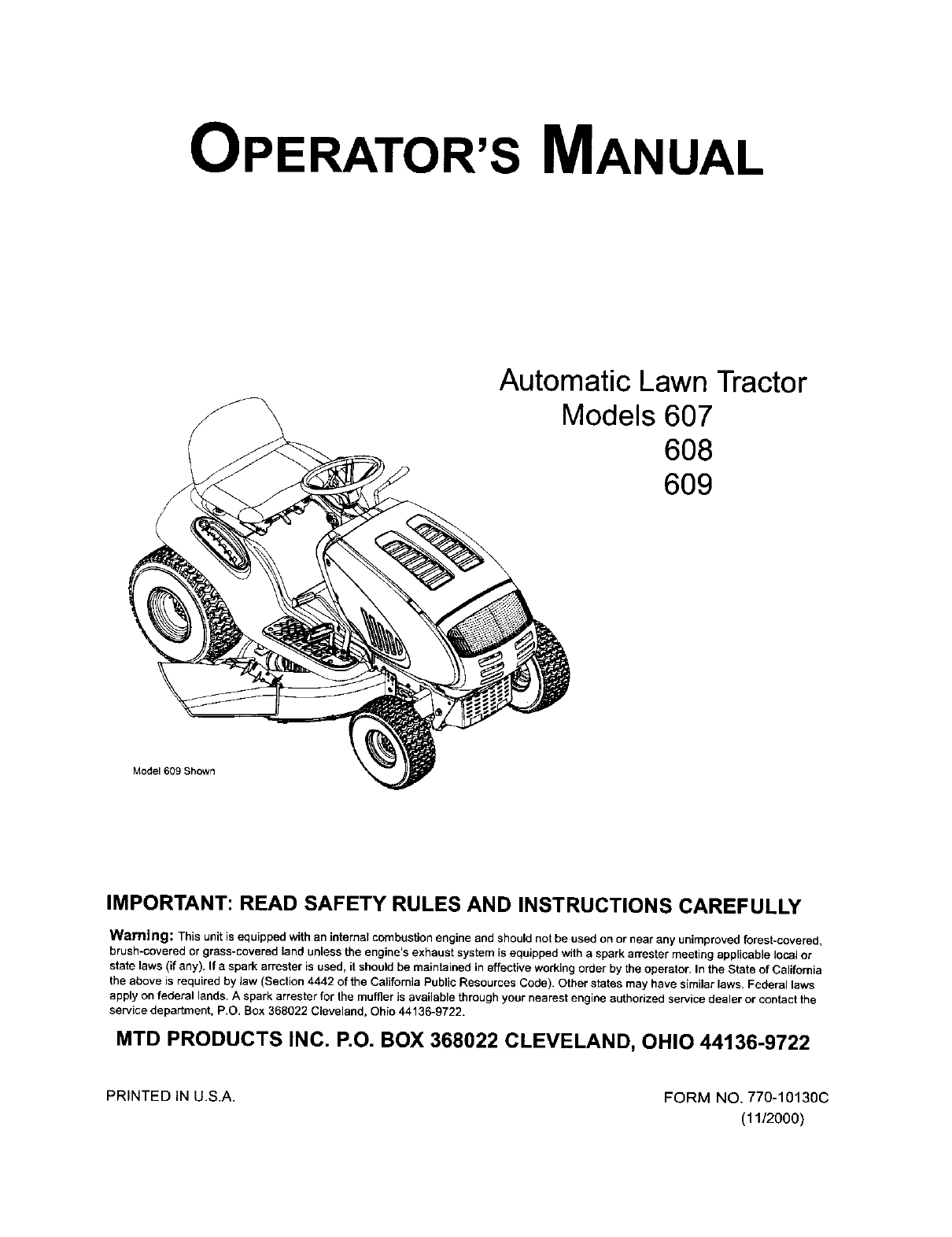
OPERATOR'S MANUAL
Automatic Lawn Tractor
Models 607
6O8
6O9
Model 609 Shown
IMPORTANT: READ SAFETY RULES AND INSTRUCTIONS CAREFULLY
Warning: This unit is equipped with an internal combustion engine and should not be used on or near any unimproved forest-covered,
brush-covered or grass-covered land unlessthe engine's exhaust system is equipped with aspark arrester meeting applicable IocaJor
state laws (if any). If a spark arrester is used, itshould be maintained in effective working order by the operator. In the State of California
the above is required by Jaw(Section 4442 of the Cafflomia PublicResources Code). Other states may have similarlaws. Federal laws
apply on federal lands. Aspark arrester for the muffler is available throughyour nearest engine authorized service dealer or contact the
service department, P.O. Box 368022 Cleveland, Ohio 44136-9722.
MTD PRODUCTS INC. P.O. BOX 368022 CLEVELAND, OHIO 44136-9722
PRINTED IN U.S.A, FORM NO, 770-10130C
(11/2000)
TABLEOFCONTENTS
Content Page
Important Safe Operation Practices ................................................................... 3
Slope Gauge ...................................................................................................... 7
Tractor Set-up .................................................................................................... 8
Know Your Lawn Tractor .................................................................................... 9
Operating Your Lawn Tractor ............................................................................. 12
Making Adjustments .......................................................................................... 16
Maintaining Your Lawn Tractor .......................................................................... 18
Service ............................................................................................................... 19
Off-Season Storage ........................................................................................... 24
Attachments & Accessories ............................................................................... 24
Troubleshooting ................................................................................................. 25
Models 607, 608 & 609 Parts List ....................................................................... 26
FINDINGMODELNUMBER
This Operator's Manual is an important part of your new lawn tractor. It will help you assemble, prepare and
maintain the unit for best performance. Please read and understand what it says.
r
Before you start assembling your new equipment, please locate the model plate on the
equipment and copy the information from it in the space provided below. The information on the
model plate is very important ifyou need help from our Customer Support Department or an
authorized dealer.
You can locate the model number by looking beneath the seat. A sample model plate is explained below.
For future reference, please copy the model number and the serial number of the equipment in the space
below.
(Model Number) (Serial Number)
MTD PRODUCTS INC
P.O. BOX 368022
CLEVELAND, OHIO 44136
Copy the model number here:
Copy the serial number here:
CALLINGCUSTOMERSUPPORT
If you have difficulty assembling this product or have any questions regarding the controls, operation or
maintenance of this unit, please call the Customer Support Department.
Call 1- (330) 220-4MTD (4683) or 1- (800)-800-7310 to reach a Customer Support
representative. Please have your unit's model number and serial number ready when you call.
See previous section to locate this information. You will be asked to enter the serial number in
order to process your call.
SECTION1: IMPORTANTSAFEOPERATIONPRACTICES
WARNING: This symbol points out important safety instructions which, if not followed, could endanger
the personal safety and/or property of yourself and others. Read and follow all instructions in this manual
before attempting to operate this machine. Failure to comply with these instructions may result in personal
injury. When you see this symbol--heed its warning.
DANGER: This machine was built to be operated according to the rules for safe operation in this man-
ual. As with any type of power equipment, carelessness or error on the part of the operator can result in
serious injury. This machine is capable of amputating hands and feet and throwing objects. Failure to
observe the following safety instructions could result in serious injury or death.
California Proposition 65 Warning:
WARNING: Engine exhaust, some of its constituents, and certain vehicle components contain
or emit chemicals known to the State of California to cause cancer and birth defects or other
reproductive harm.
GENERAL OPERATION
1. Read, understand, and follow all instructions on the
machine and in the manual(s) before attempting to
assemble and operate. Keep this manual in a safe
place for future and regular reference and for
ordering replacement parts.
2. Be familiar with all controls and their proper
operation. Know how to stop the machine and
disengage them quickly.
3. Never allow children under 14 years old to operate
this machine. Children 14 years old and over
should read and understand the operation
instructions and safety rules in this manual and
should be trained and supervised by a parent.
4. Never allow adults to operate this machine without
proper instruction.
5. To help avoid blade contact or a thrown object
injury, keep bystanders, helpers, children and pets
at least 75 feet from the machine while it is in
operation. Stop machine if anyone enters the area.
6. Thoroughly inspect the area where the equipment
is to be used. Remove all stones, sucks, wire,
bones, toys, and other foreign objects which could
be picked up and thrown by the blade(s). Thrown
objects can cause serious personal injury.
7. Plan your mowing pattern to avoid discharge of
material toward roads, sidewalks, bystanders and
the like. Also, avoid discharging material against a
wall or obstruction which may cause discharged
material to ricochet back toward the operator.
8. Always wear safety glasses or safety goggles
during operation and while performing an
adjustment or repair to protect your eyes. Thrown
objects which ricochet can cause serious injury to
the eyes.
9. Wear sturdy, rough-soled work shoes and close-
fitting slacks and shirts. Loose fitting clothes and
jewelry can be caught in movable parts. Never
operate this machine in bare feet or sandals.
10. Be aware of the mower and attachment discharge
direction and do not point it at anyone. Do not
operate the mower without the discharge cover or
entire grass catcher in its proper place.
11. Do not put hands or feet near rotating parts or
under the cutting deck. Contact with the blade(s)
can amputate hands and feet.
12. A missing or damaged discharge cover can cause
blade contact or thrown object injuries.
13. Stop the blade(s) when crossing gravel drives,
walks, or roads and while not cutting grass.
14. Watch for traffic when operating near or crossing
roadways. This machine is not intended for use on
any public roadway.
15. Do not operate the machine while under the
influence of alcohol or drugs.
16. Mow only in daylight or good artificial light.
17. Never carry passengers.
18. Disengage blade(s) before shitting into reverse.
Back up slowly. Always look down and behind
before and while backing to avoid a back-over
accident.
19. Slow down before turning. Operate the machine
smoothly. Avoid erratic operation and excessive
speed.
20. Disengage blade(s), set parking brake, stop engine
and wait until the blade(s) come to a complete stop
before removing grass catcher, emptying grass,
unclogging chute, removing any grass or debris, or
making any adjustments.
21. Neverleave a running machine unattended. Always
turn off blade(s), place transmission in neutral, set
parking brake, stop engine and remove key before
dismounting.
22. Use extra care when loading or unloading the
machine into a trailer or truck. This unit should not
be driven up or down ramp(s), because the unit
could tip over, causing serious personal injury. The
unit must be pushed manually on ramp(s) to load or
unload properly.
23.Mufflerandenginebecomehotandcancausea
bum. Do not touch.
24. Check overhead clearances carefully before driving
under low hanging tree branches, wires, door
openings etc., where the operator may be struck or
pulled from the unit, which could result in serious
injury.
25. Disengage all attachment clutches, depress the
brake pedal completely and shift into neutral before
attempting to start engine.
26. Your machine is designed to cut normal residential
grass of a height no more than 10". Do not attempt
to mow through unusually tall, dry grass (e.g.,
pasture) or piles of dry leaves. Dry grass or leaves
may contact the engine exhaust and/or build up on
the mower deck presenting a potential fire hazard.
27. Use only accessories and attachments approved
for this machine by the machine manufacturer.
Read, understand and follow all instructions
provided with the approved accessory or
attachment.
28. Data indicates that operators, age 60 years and
above, are involved in a large percentage of riding
mower-related injuries. These operators should
evaluate their ability to operate the riding mower
safely enough to protect themselves and others
from serious injury.
29. If situations occur which are not covered in this
manual, use care and good judgment. Contact an
authorized MTD Service Dealer for assistance.
SLOPE OPERATION
Slopes are a major factor related to loss of control and
tip-over accidents which can result in severe injury or
death. All slopes require extra caution. If you cannot
back up the slope or if you feel uneasy on it, do not mow
it.
For your safety, use the slope gauge included as part of
this manual to measure slopes before operating this
unit on a sloped or hilly area. If the slope is greater than
15 degrees as shown on the slope gauge, do not
operate this unit on that area or serious injury could
result.
DO:
1. Mow up and down slopes, not across. Exercise
extreme caution when changing direction on
slopes.
2. Watch for holes, ruts, bumps, rocks, or other
hidden objects. Uneven terrain could overturn the
machine. Tall grass can hide obstacles.
3. Use slow speed. Choose a low enough speed
setting so that you will not have to stop or shift while
on the slope. Tires may lose traction on slopes
even though the brakes are functioning properly.
Always keep machine in gear when going down
slopes to take advantage of engine braking action.
4. Follow the manufacturer's recommendations for
wheel weights or counterweights to improve
stability.
5. Use extra care with grass catchers or other
attachments. These can change the stability of the
machine.
6. Keep all movement on the slopes slow and gradual.
Do not make sudden changes in speed or direction.
Rapid engagement or braking could cause the front
of the machine to lift and rapidly flip over backwards
which could cause serious injury.
7. Avoid starting or stopping on a slope, if tires lose
traction, disengage the blade(s) and proceed
slowly straight down the slope.
DO NOT:
1. Do not turn on slopes unless necessary; then, turn
slowly and gradually downhill, if possible.
2. Do not mow near drop-offs, ditches or
embankments. The mower could suddenly turn
over if a wheel is over the edge of a cliff, ditch, or if
an edge caves in.
3. Do not try to stabilize the machine by putting your
foot on the ground.
4. Do not use a grass catcher on steep slopes,
5. Do not mow on wet grass. Reduced traction could
cause sliding.
6. Do not shift to neutral and coast downhill. Over-
speeding may cause the operator to lose control of
the machine resulting in serious injury or death.
7. Do not tow heavy pull behind attachments (e.g.
loaded dump cart, lawn roller, etc.) on slopes
greater than 5 degrees. When going down hill, the
extra weight tends to push the tractor and may
cause you to loose control. (e.g. tractor may speed
up, braking and steering ability are reduced,
attachment may jack-knife and cause tractor to
overturn).
CHILDREN
1. Tragic accidents can occur if the operator is not
alert to the presence of children. Children are often
attracted to the machine and the mowing activity.
They do not understand the dangers. Never
assume that children will remain where you last
saw them.
a. Keep children out of the mowing area and in
watchful care of a responsible adult other
than the operator.
b. Be alert and turn machine off if a child enters
the area.
c. Before and while backing, look behind and
down for small children.
d. Never carry children, even with the blade(s)
shut off. They may fall off and be seriously
injured or interfere with safe machine
operation.
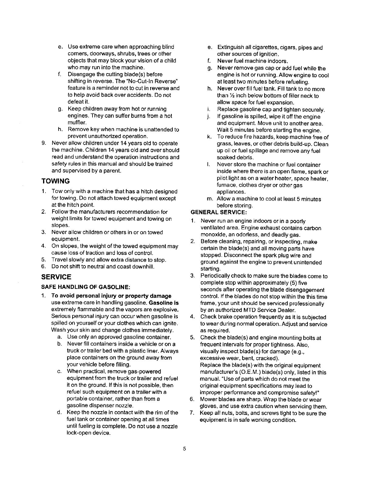
e. Useextremecarewhenapproachingblind
comers,doorways,shrubs,treesorother
objectsthatmayblockyourvisionofachild
whomayrunintothemachine.
f. Disengagethecuttingblade(s)before
shittinginreverse.The"No-Cut-InReverse"
featureisaremindernottocutinreverseand
tohelpavoidbackoveraccidents.Donot
defeatit.
g. Keepchildrenawayfromhotorrunning
engines.Theycansufferburnsfromahot
muffler.
h. Removekeywhenmachineisunattendedto
preventunauthorizedoperation.
9. Neverallowchildrenunder14yearsoldtooperate
themachine.Children14yearsoldandovershould
readandunderstandtheoperationinstructionsand
safetyrulesinthismanualandshouldbetrained
andsupervisedbyaparent.
TOWING
1. Towonlywithamachinethathasahitchdesigned
fortowing.Donotattachtowedequipmentexcept
atthehitchpoint.
2. Followthemanufacturersrecommendationfor
weightlimitsfortowedequipmentandtowingon
slopes.
3. Neverallowchildrenorothersinorontowed
equipment.
4. Onslopes,theweightofthetowedequipmentmay
causelossoftractionandlossofcontrol.
5. Travelslowlyandallow extra distance to stop.
6. Do not shift to neutral and coast downhill.
SERVICE
SAFE HANDLING OF GASOLINE:
1. To avoid personal injury or property damage
use extreme care in handling gasoline. Gasoline is
extremely flammable and the vapors are explosive.
Serious personal injury can occur when gasoline is
spilled on yourself or your clothes which can ignite.
Wash your skin and change clothes immediately.
a. Use only an approved gasoline container.
b. Never fill containers inside a vehicle or on a
truck or trailer bed with a plastic liner. Always
place containers on the ground away from
your vehicle before filling.
c. When practical, remove gas-powered
equipment from the truck or trailer and refuel
it on the ground. If this is not possible, then
refuel such equipment on a trailer with a
portable container, rather than from a
gasoline dispenser nozzle.
d. Keep the nozzle in contact with the rim of the
fuel tank or container opening at all times
until fueling is complete. Do not use a nozzle
lock-open device.
e. Extinguish all cigarettes, cigars, pipes and
other sources of ignition.
f. Never fuel machine indoors.
g. Never remove gas cap or add fuel while the
engine is hot or running. Allow engine to cool
at least two minutes before refueling.
h. Never over fill fuel tank. Fill tank to no more
than ½ inch below bottom of filler neck to
allow space for fuel expansion.
i. Replace gasoline cap and tighten securely.
j. If gasoline is spilled, wipe it off the engine
and equipment. Move unit to another area.
Wait 5 minutes before starting the engine.
k. To reduce fire hazards, keep machine free of
grass, leaves, or other debris build-up. Clean
up oil or fuel spillage and remove any fuel
soaked debris.
I. Never store the machine or fuel container
inside where there is an open flame, spark or
pilot light as on a water heater, space heater,
furnace, clothes dryer or other gas
appliances.
m. Allow a machine to cool at least 5 minutes
before storing.
GENERAL SERVICE:
1. Never run an engine indoors or in a poorly
ventilated area. Engine exhaust contains carbon
monoxide, an odorless, and deadly gas.
2. Before cleaning, repairing, or inspecting, make
certain the blade(s) and all moving parts have
stopped. Disconnect the spark plug wire and
ground against the engine to prevent unintended
starting.
3. Periodically check to make sure the blades come to
complete stop within approximately (5) five
seconds after operating the blade disengagement
control. If the blades do not stop within the this time
frame, your unit should be serviced professionally
by an authorized MTD Service Dealer.
4. Check brake operation frequently as it is subjected
to wear during normal operation. Adjust and service
as required.
5. Check the blade(s) and engine mounting bolts at
frequent intervals for proper tightness. Also,
visually inspect blade(s) for damage (e.g.,
excessive wear, bent, cracked).
Replace the blade(s)with the original equipment
manufacturer's (O.E.M.) blade(s) only, listed in this
manual. "Use of parts which do not meet the
original equipment specifications may lead to
improper performance and compromise safety!"
6. Mower blades are sharp. Wrap the blade or wear
gloves, and use extra caution when servicing them.
7. Keep all nuts, bolts, and screws tight to be sure the
equipment is in safe working condition.
5
8. Never tamper with the safety interlock system or
other safety devices. Check their proper operation
regularly.
9. After striking a foreign object, stop the engine,
disconnect the spark plug wire(s) and ground
against the engine. Thoroughly inspect the
machine for any damage. Repair the damage
before starting and operating.
10. Never attempt to make adjustments or repairs to
the machine while the engine is running.
11. Grass catcher components and the discharge
cover are subject to wear and damage which could
expose moving parts or allow objects to be thrown.
12.
13.
14.
For safety protection, frequently check components
and replace immediately with original equipment
manufacturer's (O.EM.) parts only, listed in this
manual. "Use of parts which do not meet the
original equipment specifications may lead to
improper performance and compromise safety!"
Do not change the engine governor settings or
over-speed the engine. The governor controls the
maximum safe operating speed of the engine.
Maintain or replace safety and instruction labels, as
necessary.
Observe proper disposal laws and regulations for
gas, oil, etc. to protect the environment.
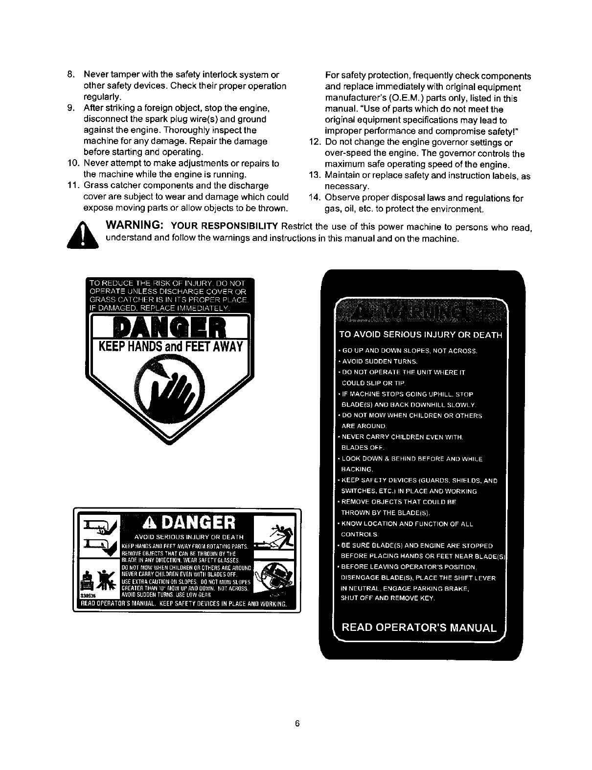
WARNING: YOUR RESPONSIBILITY Restrict the use of this power machine to persons who read,
understand and follow the warnings and instructions in this manual end on the machine.
6

I
SIGHT AND HOLD THIS LEVEL WITH A VERTICAL TREE
A POWER POLE
Z
o
i
W
Do not mow on inclines with a slope in excess of 15 degrees (a rise of approximately 2-1/2 feet every 10 feet). A riding mower
could overturn and cause serious injury. If operating a walk-behind mower on such a slope, it is extremely difficult to maintain
your footing and you could slip, resulting in serious injury.
Operate RIDING mowers up and down slopes, never across the face of slopes.
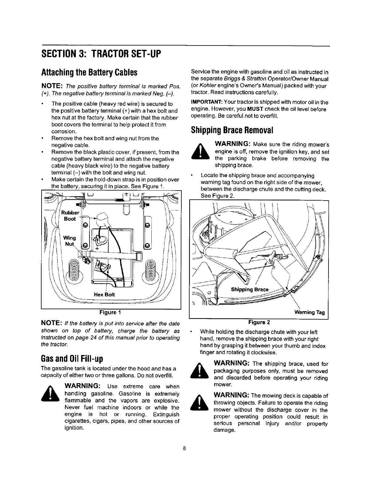
SECTION3: TRACTORSET-UP
AttachingtheBatteryCables
NOTE: The positive battery terminal is marked Pos.
(+). The negative battery terminal is marked Neg. (-).
The positive cable (heavy red wire) is secured to
the positive battery terminal (+) with a hex bolt and
hex nut at the factory. Make certain that the rubber
boot covers the terminal to help protect it from
corrosion.
Remove the hex bolt and wing nut from the
negative cable.
Remove the black plastic cover, if present, from the
negative battery terminal and attach the negative
cable (heavy black wire) to the negative battery
terminal (-) with the bolt and wing nut.
Make certain the hold-down strap is in position over
the battery, securing it in place. See Figure 1.
Figure 1
NOTE:/f the battery is put into service after the date
shown on top of battery, charge the battery as
instructed on page 24 of this manual prior to operating
the tractor.
GasandOilFill-up
The gasoline tank is located under the hood and has a
capacity of either two or three gallons. Do not overfill.
WARNING: Use extreme care when
handling gasoline. Gasoline is extremely
flammable and the vapors are explosive.
Never fuel machine indoors or while the
engine is hot or running. Extinguish
cigarettes, cigars, pipes, and other sources of
ignition.
Service the engine with gasoline and oil as instructed in
the separate Briggs & Stratton Operator/Owner Manual
(or Kohler engine's Owner's Manual) packed with your
tractor. Read instructions carefully.
IMPORTANT: Your tractor is shipped with motor oil in the
engine. However, you MUST check the oil level before
operating. Be careful not to overfill.
ShippingBraceRemoval
&WARNING: Make sure the riding mower's
engine is off, remove the ignition key, and set
the parking brake before removing the
shipping brace.
Locate the shipping brace and accompanying
warning tag found on the right side of the mower,
between the discharge chute and the cutting deck.
See Figure 2.
Warning Tag
Figure 2
While holding the discharge chute with your left
hand, remove the shipping brace with your right
hand by grasping it between your thumb and index
finger and rotating it clockwise.
WARNING: The shipping brace, used for
packaging purposes only, must be removed
and discarded before operating your riding
mower.
WARNING: The mowing deck is capable of
throwing objects. Failure to operate the riding
mower without the discharge cover in the
proper operating position could result in
serious personal injury and/or property
damage.
8
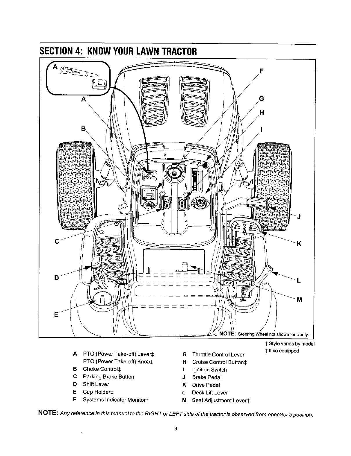
SECTION4: KNOWYOURLAWNTRACTOR
F
A
B
G
H
C
D
APTO (Power Take-off) Lever.i:
PTO (Power Take-off) Knob S
B Choke Control:l:
C Parking Brake Button
DShift Lever
E Cup Holders
F Systems Indicator Monitor1-
NOTE: SteeringWheel notshownforclarity.
1 Style varies by model
If so equipped
G Throttle Control Lever
H Cruise Control Button:l:
I Ignition Switch
J Brake Pedal
KDrive Pedar
LDeck Lift Lever
MSeat Adjustment Levers
NOTE" Any reference in this manual to the RIGHT or LEFT side of the tractor is observed from operator's position.
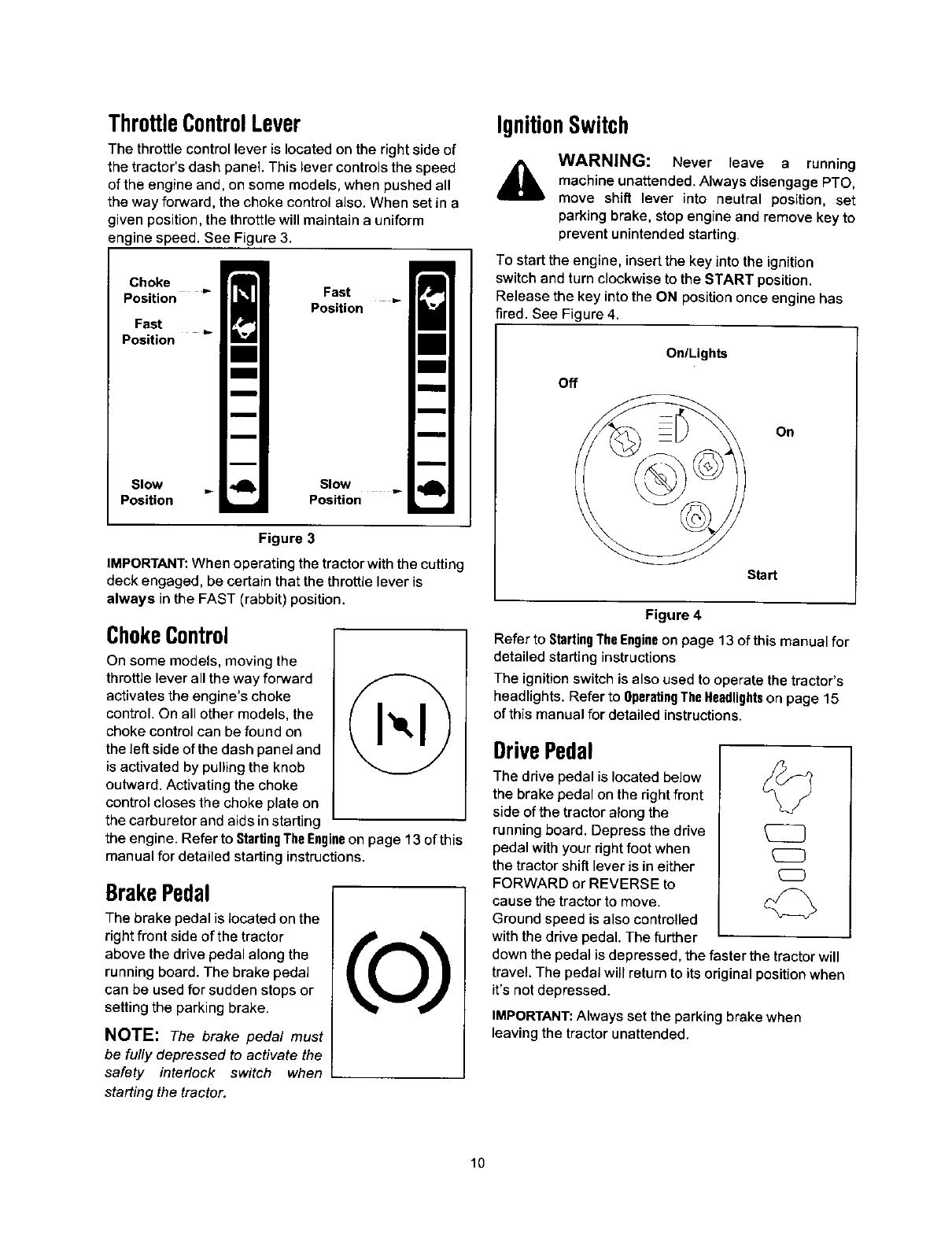
ThrottleControlLever
The throttle control lever is located on the right side of
the tractor's dash panel. This lever controls the speed
of the engine and, on some models, when pushed all
the way forward, the choke control also. When set in a
given position, the throttle will maintain a uniform
engine speed. See Figure 3.
Choke
Position _"
Fast t_
Position
Slow
Position
Fast
Position
Slow
Position
Figure 3
IMPORTANT: When operating the tractor with the cutting
deck engaged, be certain that the throttle lever is
always in the FAST (rabbit) position.
ChokeControl
On some models, moving the
throttle lever all the way forward
activates the engine's choke
control. On all other models, the
choke controJ can be found on
the left side of the dash panel and
is activated by pulling the knob
outward. Activating the choke
control closes the choke plate on
the carburetor and aids in starting
the engine. Refer to StartingThe Engineon page 13 of this
manual for detailed starting instructions.
BrakePedal
The brake pedal is Jocated on the
right front side of the tractor
above the drive pedal along the
running board. The brake pedal
can be used for sudden stops or
setting the parking brake.
NOTE: The brake pedal must
be fully depressed to activate the
safety interlock switch when
starting the tractor.
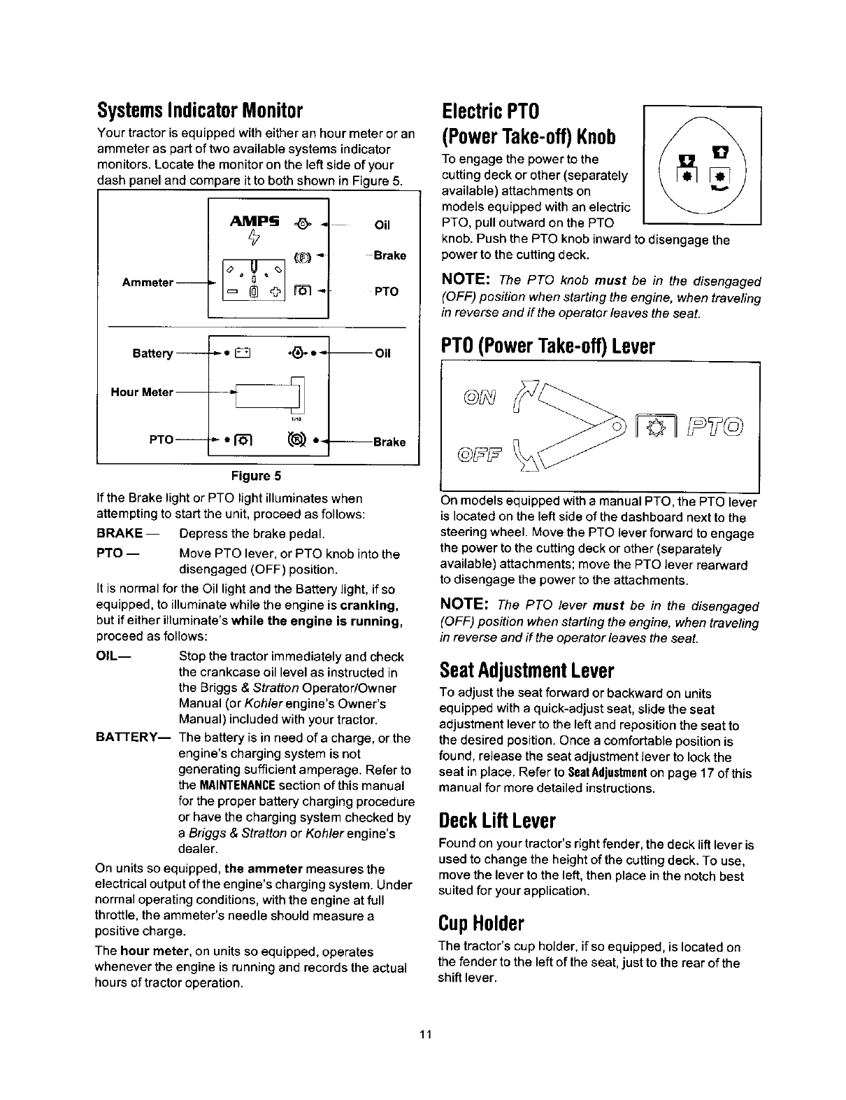
IgnitionSwitch
AWARNING: Never leave arunning
machine unattended. Always disengage PTO,
move shift lever into neutral position, set
parking brake, stop engine and remove key to
prevent unintended starting.
To start the engine, insert the key into the ignition
switch and turn clockwise to the START position.
Release the key into the ON position once engine has
fired. See Figure 4.
OnlLighta
Off
On
Start
Figure 4
Refer to StartingTheEngineon page 13 of this manual for
detailed starting instructions
The ignition switch is also used to operate the tractor's
headlights. Refer to OperatingTheHeadlightson page 15
of this manual for detailed instructions.
DrivePedal
The drive pedal is located below
the brake pedal on the right front
side of the tractor along the
running board. Depress the drive
pedal with your dght foot when
the tractor shift lever is in either
FORWARD or REVERSE to
cause the tractor to move.
Ground speed is also controlled
with the drive pedal The further
down the pedal is depressed, the faster the tractor will
travel. The pedal will return to its original position when
it's not depressed.
IMPORTANT: Always set the parking brake when
leaving the tractor unattended.
10
SystemsIndicatorMonitor
Your tractor is equipped with either an hour meter or an
ammeter as part of two available systems indicator
monitors. Locate the monitor on the left side of your
dash panel and compare it to both shown in Figure 5.
Ammeter--
AuMPS _. Oil
Brake
PTO
Battery --
Hour Meter--
PTO --
-.-. r_ ,_. °-. --Oil
--Brake
Figure 5
If the Brake light or PTO light illuminates when
attempting to start the unit, proceed as follows:
BRAKE -- Depress the brake pedal.
PTO -- Move PTO lever, or PTO knob into the
disengaged (OFF) position.
It is normal for the Oil light and the Battery light, if so
equipped, to illuminate while the engine is cranking,
but if either illuminate's while the engine is running,
proceed as follows:
OIL--
BATTERY--
Stop the tractor immediately and check
the crankcase oil level as instructed in
the Briggs & Stratton Operator/Owner
Manual (or Kohler engine's Owner's
Manual) included with your tractor.
The battery is in need of a charge, or the
engine's charging system is not
generating sufficient amperage. Refer to
the MAINTENANCEsection of this manual
for the proper battery charging procedure
or have the charging system checked by
aBriggs &Stratton or Koh/erengine's
dealer.
On units so equipped, the ammeter measures the
electrical output of the engine's charging system. Under
normal operating conditions, with the engine at full
throttle, the ammeter's needle should measure a
positive charge.
The hour meter, on units so equipped, operates
whenever the engine is running and records the actual
hours of tractor operation.
ElectricPTO
(PowerTake-off)Knob
To engage the power to the
cutting deck or other (separately
available) attachments on _'_
models equipped with an electric
PTO, pull outward on the PTO
knob. Push the PTO knob inward to disengage the
power to the cutting deck.
NOTE: The PTO knob must be in the disengaged
(OFF) position when starting the engine, when traveling
in reverse and if the operator leaves the seat.
PTO(PowerTake-off)Lever
On models equipped with a manual PTO, the PTO lever
is located on the left side of the dashboard next to the
steering wheel. Move the PTO lever forward to engage
the power to the cutting deck or other (separately
available) attachments; move the PTO lever rearward
to disengage the power to the attachments.
NOTE: The PTO lever must be in the disengaged
(OFF) position when starting the engine, when traveling
in reverse and if the operator leaves the seat.
SeatAdjustmentLever
To adjust the seat forward or backward on units
equipped with a quick-adjust seat, slide the seat
adjustment lever to the left and reposition the seat to
the desired position. Once a comfortable position is
found, release the seat adjustment lever to lock the
seat in place. Refer to SeatAdjustmenton page 17 of this
manual for more detailed instructions.
DeckLiftLever
Found on your tractor's right fender, the deck lift lever is
used to change the height of the cutting deck. To use,
move the lever to the left, then place in the notch best
suited for your application.
CupHolder
The tractor's cup holder, if so equipped, is located on
the fender to the left of the seat, just to the rear of the
shift lever.
11
ParkingBrakeButton
To set the parking brake, fully _'_ll_l L
depress the brake pedal and k.E/)
push the parking brake button in.
Hold the button in while taking
your foot off the brake pedal.
Both the parking button and the
brake pedal will then stay
depressed. To release the
parking brake, depress the brake
pedal slightly. The parking brake
button will then return to its original position.
NOTE: The parking brake must be set if the operator
leaves the seat with the engine running or the engine
will automatically shut off.
IMPORTANT: Always set the parking brake when
leaving the tractor unattended.
CruiseControlButton
The cruise control button, on
models so equipped, is located ;l_l
on the tractor dash panel to the
left of the ignition switch. Push
the cruise control button while
traveling forward at a desired
speed. While holding the button
in, release pressure from the
drive pedal. This will engage the
cruise control and allow the
tractor to remain at that speed without applying
pressure to the drive pedal. Depress the brake pedal or
the drive pedal to deactivate cruise control. Refer to
Settingthe CruiseControlon page 14 this manual for
detailed instructions regarding the cruise control
feature.
NOTE: Cruise control can NOT be engaged at the
tractor's fastest ground speed. If the operator should
attempt to do so, the tractor will automatically
decelerate to the fastest optimal mowing ground speed.
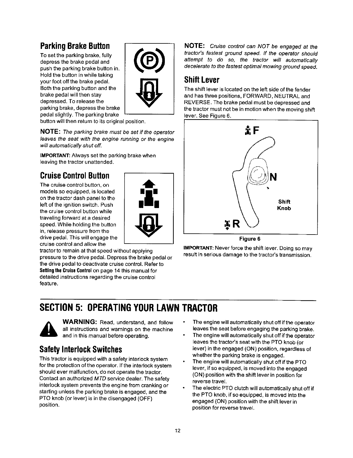
ShiftLever
The shift lever is located on the left side of the fender
and has three positions, FORWARD, NEUTRAL and
REVERSE. The brake pedal must be depressed and
the tractor must not be in motion when the moving shift
lever. See Figure 6.
Shift
Knob
Figure 6
IMPORTANT: Never force the shift Jever. Doing so may
result in serious damage to the tractor's transmission.
SECTION5: OPERATINGYOURLAWNTRACTOR
WARNING: Read, understand, and follow
all instructions and warnings on the machine
and in this manual before operating.
SafetyInterlockSwitches
This tractor is equipped with a safety interlock system
for the protection of the operator. If the interlock system
should ever malfunction, do not operate the tractor.
Contact an authorized MTD service dealer. The safety
interlock system prevents the engine from cranking or
starting unless the parking brake is engaged, and the
PTO knob (or lever) is in the disengaged (OFF)
position.
The engine will automatically shut off if the operator
leaves the seat before engaging the parking brake.
The engine will automatically shut off if the operator
leaves the tractor's seat with the PTO knob (or
lever) in the engaged (ON) position, regardless of
whether the parking brake is engaged.
The engine will automatically shut off if the PTO
lever, if so equipped, is moved into the engaged
(ON) position with the shift lever in position for
reverse travel.
The electric PTO clutch will automatically shut off if
the PTO knob, if so equipped, is moved into the
engaged (ON) position with the shift lever in
position for reverse travel.
12
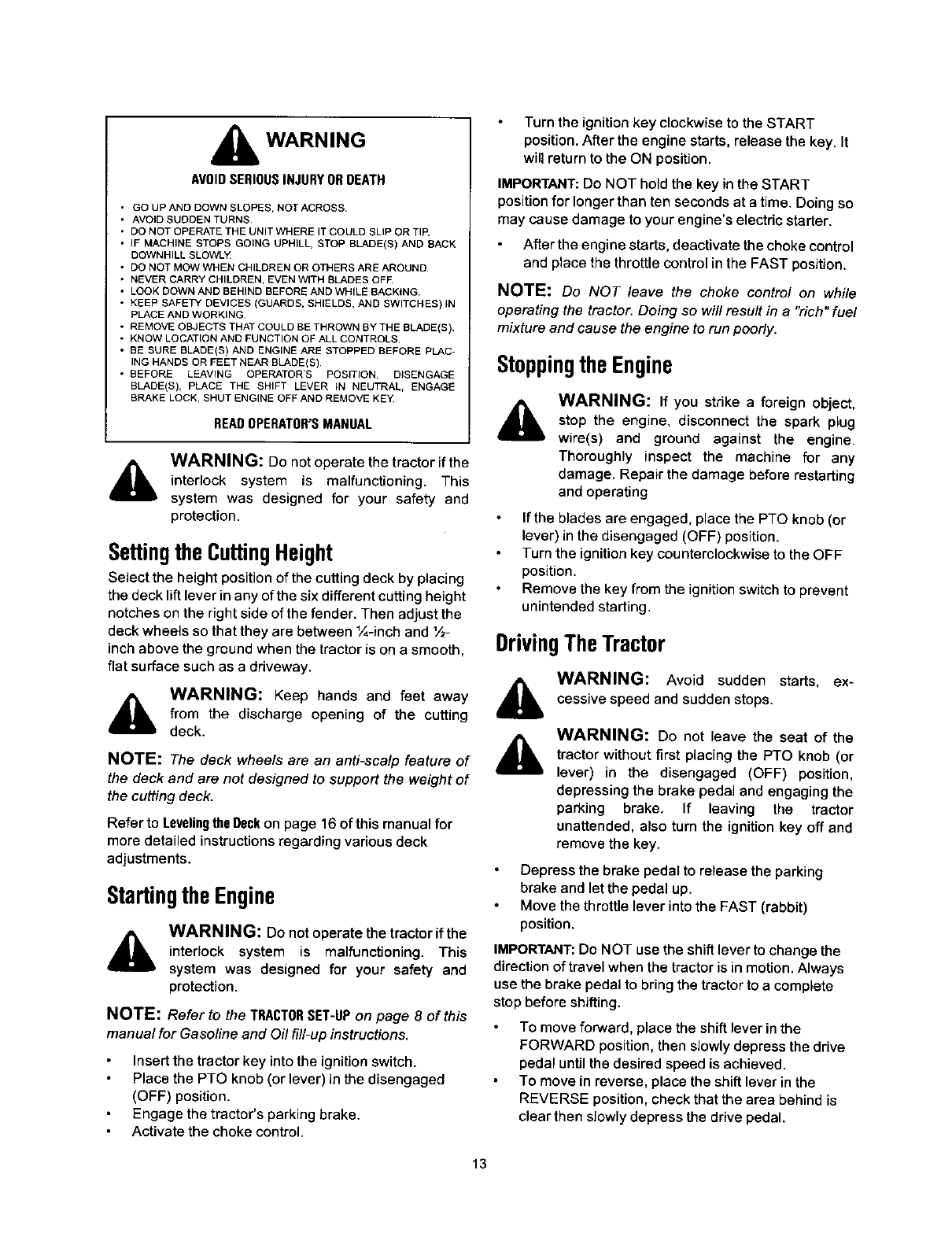
WARNING
AVOIDSERIOUSINJURYORDEATH
• GO UP AND DOWN SLOPES, NOT ACROSS.
•AVOID SUDDEN TURNS
•DO NOT OPERATE THE UNIT WHERE IT COULD SLIP OR TIP,
•IF MACHINE STOPS GOING UPHILL, STOP BL_,DE(S) AND SACK
DOWNHILL SLOWLY.
•DO NOT MOW WHEN CHILDREN OR OTHERS ARE AROUND,
•NEVER CARRY CHILDREN, EVEN WrTH BLADES OFF,
•LOOK DOWN AND BEHIND BEFORE AND WHILE BACKING,
•KEEP SAFETY DEVICES (GUARDS, SHIELDS, AND SWITCHES) IN
PLACE AND WORKING
•REMOVE OBJECTS THAT COULD BE THROWN BY THE BLADE(S),
• KNOW LOCATION AND FUNCTION OF ALL CONTROLS
•BE SURE BLADE(S) AND ENGINE ARE STOPPED BEFORE PLAC-
ING HANDS OR FEET NEAR BLADE(S)
• BEFORE LEAVING OPERATOR'S POSITION, DISENGAGE
BLADE(S), PLACE THE SHIFT LEVER IN NEUTRAL, ENGAGE
BRAKE LOCK. SHUT ENGINE OFF AND REMOVE KEY
READOPERATOR'SMANUAL
&WARNING: Do not operate the tractor if the
interlock system is malfunctioning. This
system was designed for your safety and
protection.
Settingthe CuttingHeight
SeJect the height position of the cutting deck by placing
the deck lift lever in any of the six different cutting height
notches on the right side of the fender. Then adjust the
deck wheels so that they are between 1/4-inchand ½-
inch above the ground when the tractor is on a smooth,
flat surface such as a driveway.
,_ WARNING: Keep hands and feet away
from the discharge opening of the cutting
deck.
NOTE: The deck wheels are an anti-scalp feature of
the deck and are not designed to support the weight of
the cutting deck.
Refer to LevelingtheDeckon page 16 of this manual for
more detailed instructions regarding various deck
adjustments,
StartingtheEngine
AWARNING: Do not operate the tractor if the
interlock system is malfunctioning. This
system was designed for your safety and
protection.
NOTE: Refer to the TRACTORSET-UPon page 8 of this
manual for Gasoline and Oil fill-up instructions.
Insert the tractor key into the ignition switch.
Place the PTO knob (or lever) in the disengaged
(OFF) position.
Engage the tractor's parking brake.
Activate the choke control.
Turn the ignition key clockwise to the START
position. After the engine starts, release the key. It
will return to the ON position.
IMPORTANT: Do NOT hold the key in the START
position for longer than ten seconds at a time. Doing so
may cause damage to your engine's electric starter.
After the engine starts, deactivate the choke control
and place the throttle control in the FAST position.
NOTE: Do NOT leave the choke control on while
operating the tractor. Doing so will result in a "rich" fuel
mixture and cause the engine to run poorly.
Stoppingthe Engine
AWARNING: If you strike aforeign object,
stop the engine, disconnect the spark plug
wire(s) and ground against the engine.
Thoroughly inspect the machine for any
damage. Repair the damage before restarting
and operating
If the blades are engaged, place the PTO knob (or
lever) in the disengaged (OFF) position.
Turn the ignition key counterclockwise to the OFF
position.
Remove the key from the ignition switch to prevent
unintended starting.
DrivingTheTractor
,_ WARNING: Avoid sudden starts, ex-
cessive speed and sudden stops.
WARNING: Do not leave the seat of the
tractor without first placing the PTO knob (or
lever) in the disengaged (OFF) position,
depressing the brake pedal and engaging the
parking brake. If leaving the tractor
unattended, also turn the ignition key off and
remove the key.
Depress the brake pedal to release the parking
brake and let the pedal up.
Move the throttle lever into the FAST (rabbit)
position.
IMPORTANT: Do NOT use the shift lever to change the
direction of travel when the tractor is in motion. Always
use the brake pedal to bring the tractor to a complete
stop before shifting.
To move forward, place the shift lever in the
FORWARD position, then slowly depress the drive
pedal until the desired speed is achieved.
To move in reverse, place the shift lever in the
REVERSE position, check that the area behind is
clear then slowly depress the drive pedal.
13
EngagingtheParkingBrake
To engage the parking brake:
Fully depress the brake pedal and hold it down with
your foot while gently pushing the parking brake
button inward.
Hold the parking brake button in while removing
your foot from the brake pedal.
Once engaged, the parking brake button and the
brake pedal will lock in the "down" position.
To disengage the parking brake:
Slightly depress the brake pedal.
NOTE: The parking brake must be engaged if the
operator leaves the seat with the engine running or the
engine will automatically shut off.
DrivingOnSlopes
Refer to the SLOPEGAUGEon page 7 to help determine
slopes where you may operate the tractor safely.
WARNING: Do not mow on inclines with a
slope in excess of 15 degrees (a rise of
approximately 2-1/2 feet every 10 feet). The
tractor could overturn and cause serious
injury.
Mow up and down slopes, NEVER across.
Exercise extreme caution when changing direction
on slopes.
Watch for holes, ruts, bumps, rocks, or other
hidden objects. Uneven terrain could overturn the
machine. Tall grass can hide obstacles.
Avoid turns when driving on a slope. If a turn must
be made, turn down the slope. Turning up a slope
greatly increases the chance of a roll over.
Avoid stopping when driving up a slope. If it is
necessary to stop while driving up a slope, start up
smoothly and carefully to reduce the possibility of
flipping the tractor over backward.
SettingTheCruiseControl
NOTE: The cruise control feature is NOTstandard on
all models.
Place the shift lever in the FORWARD position,
then slowly depress the drive pedal until the desired
speed is achieved.
Lightly depress the cruise control button.
While continuing to hold the cruise button in, lift
your foot from the drive pedal (you should feel the
cruise latch engage).
Once engaged, the cruise control button and the
drive pedal will lock in the "down" position, and the
tractor will maintain the same forward speed.
NOTE: Cruise control can not be engaged at the
tractor's fastest ground speed. If the operator should
attempt to do so, the tractor will automatically
decelerate to the fastest optimal mowing ground speed.
Disengage the cruise control using one of the following
methods:
Depress the brake pedal to disengage the cruise
control and stop the tractor.
Lightly depress the drive pedal.
To change to the reverse direction when operating with
cruise control, depress the brake pedal to disengage
the cruise control and bring the tractor to a complete
stop. Then place the shift lever in the REVERSE
position and depress the drive pedal.
EngagingthePTO
Engaging the PTO transfers power to the cutting deck
or other (separately available) attachments. To engage
the PTO, proceed as follows:
Move the throttle control lever to the FAST (rabbit)
position.
ModelswithManualPTO
Grasp the PTO lever and pivot it all the way forward
into the engaged (ON) position.
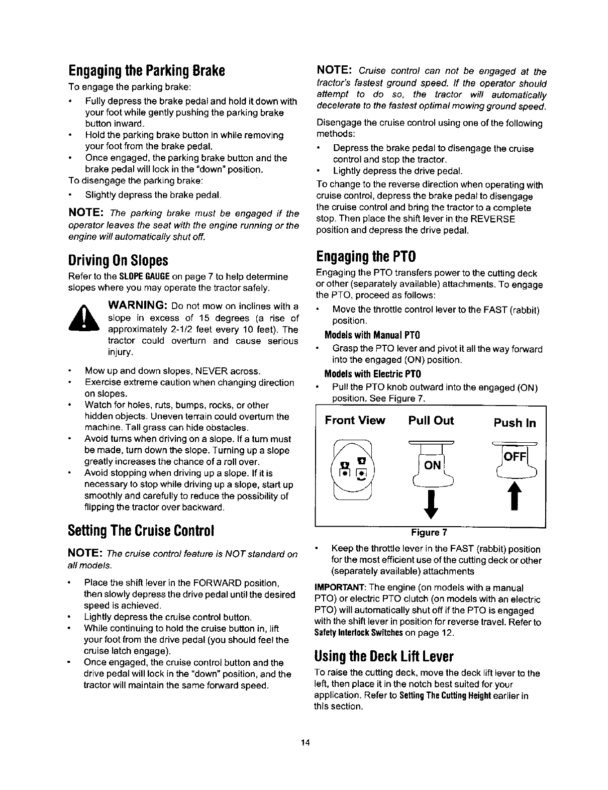
Models with Electric PTO
Pull the PTO knob outward into the engaged (ON)
position. See Figure 7.
Front View Pull Out Push In
Figure 7
Keep the throttle lever in the FAST (rabbit) position
for the most efficient use of the cutting deck or other
(separately available) attachments
IMPORTANT: The engine (on models with a manual
PTO) or electric PTO clutch (on models with an electric
PTO) will automatically shut off if the PTO is engaged
with the shift lever in position for reverse travel, Refer to
SafetyInterlockSwitcheson page 12.
UsingtheDeckLift Lever
To raise the cutting deck, move the deck lift lever to the
left, then place it in the notch best suited for your
application. Refer to SettingThe CuttingHeightearlier in
this section.
14
Mowing
AWARNING: To help avoid blade contact or
a thrown object injury, keep bystanders,
helpers, children and pets at least 75 feet
from the machine while it is in operation. Stop
machine if anyone enters the area.
This tractor is equipped with one of MTD's high quality
cutting decks. The following information will be helpful
when using the cutting deck with your tractor.
AWARNING: Plan your mowing pattern to
avoid discharge of materials toward roads,
sidewalks, bystanders and the like. Also,
avoid discharging material against a wall or
obstruction which may cause discharged
material to ricochet back toward the operator.
Do not mow at high ground speed, especially if a
mulch kit or grass collector is installed.
For best results it is recommended that the first two
laps be cut with the discharge thrown towards the
center. After the first two laps, reverse the direction
to throw the discharge to the outside for the
balance of cutting. This wil_ give a better
appearance to the lawn.
Do not cut the grass too short. Short grass invites
weed growth and yellows quickly in dry weather.
Mowing should always be done with the engine at
full throttle.
Under heavier conditions it may be necessary to go
back over the cut area a second time to get a clean
cut.
Do NOT attempt to mow heavy brush and weeds
and extremely tall grass. Your tractor is designed to
mow lawns, NOT clear brush.
Keep the blades sharp and replace the blades
when worn. Refer to CuttingBladeson page 20 of this
manuaJ for proper blade sharpening instructions.
Mulching
Some, NOT all, models come equipped with a mulch kit
which incorporates special blades, already standard on
your tractor, in aprocess of recirculating grass clippings
repeatedly beneath the cutting deck. The ultra-fine
clippings are then forced back into the lawn where they
act as a natural fertilizer. Observe the following points
for the best results when muiching.
Never attempt to mulch if the lawn is damp. Wet
grass tends to stick to the underside of the cutting
deck preventing proper mulching of the clippings.
Do NOT attempt to mulch more than 1/3 the total
height of the grass or approximately 1-1/2 inches.
Doing so will cause the clippings to clump up
beneath the deck and not be mulched effectively.
Maintain a slow ground speed to allow the grass
clippings more time to effectively be mulched.
Always position the throttle control lever in the
FAST (rabbit) position and allow it to remain there
while mowing. Failing to keep the engine at full
throttle places strain on the tractor's engine and
does not allow the blades to properly mulch grass.
NOTE: It is not necessary to remove the discharge
chute to operate the mower with the mulch kit installed.
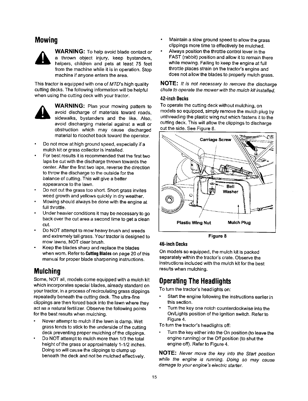
42-inch Decks
To operate the cutting deck without mulching, on
models so equipped, simply remove the mulch plug by
unthreading the plastic wing nut which fastens it to the
cutting deck. This will allow the clippings to discharge
out the side. See Figure 8.
Carriage
Plastic Wing Nut Mulch Plug
Figure 8
46-inch Decks
On models so equipped, the mulch kit is packed
separately within the tractor's crate. Observe the
instructions included with the mulch kit for the best
results when mulching.
OperatingTheHeadlights
To turn the tractor's headlights on:
Start the engine following the instructions earlier in
this section.
Turn the key one notch counterclockwise into the
On/Lights position of the ignition switch. Refer to
Figure 4.
To turn the tractor's headlights off:
Turn the key either into the On position (to leave the
engine running) or the Off position (to shut the
engine off). Refer to Figure 4.
NOTE: Never move the key into the Start position
while the engine is running. Doing so may cause
damage to your engine's electric starter.
15
SECTION6: MAKINGADJUSTMENTS
&WARNING: Never attempt to make any
adjustments while the engine is running,
except where specified in the operator's
manual.
_, WARNING: Disconnect the spark plug
wire(s) and ground against the engine before
performing any adjustments, repairs or
maintenance.
LevelingtheDeck
NOTE: Check the tractor's tire pressure before
performing any deck leveling adjustments. Refer to
Tires on page 19 for information regarding tire pressure.
Front To Rear
The front of the cutting deck is supported by a stabilizer
bar that can adjusted to level the deck from front to rear.
The front of the deck should be between 1/4-inch and
3/8-inch lower than the rear of the deck. Adjust if
necessary as follows:
With the tractor parked on a firm, level surface,
place the deck lift lever in the top notch (highest
position) and rotate the blade nearest the discharge
chute so that it is parallel with the tractor.
Measure the distance from the front of the blade tip
to the ground and the rear of the blade tip to the
ground.
The first measurement taken should be between
1/4" and 3/8" less than the second measurement.
Determine the approximate distance necessary for
proper adjustment and proceed, if necessary, to the
next step.
A_ Lock
Nuts
Deck _' _ I "_
Stabilizer
Bracket
Deck Jam
Nuts
FRON_
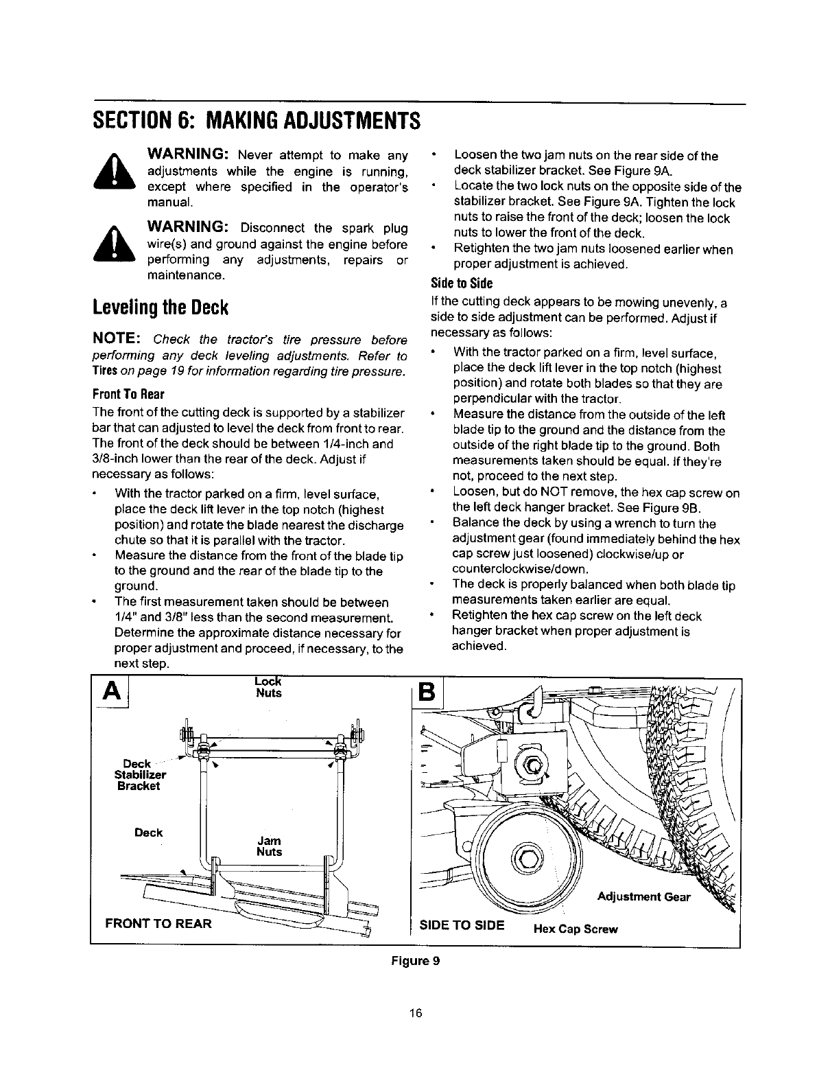
Loosen the two jam nuts on the rear side of the
deck stabilizer bracket. See Figure 9A.
Locate the two lock nuts on the opposite side of the
stabilizer bracket. See Figure 9A. Tighten the lock
nuts to raise the front of the deck; loosen the lock
nuts to lower the front of the deck.
Retighten the two jam nuts loosened earlier when
proper adjustment is achieved.
Sideto Side
If the cutting deck appears to be mowing unevenly, a
side to side adjustment can be performed. Adjust if
necessary as follows:
With the tractor parked on a firm, level surface,
place the deck lift lever in the top notch (highest
position) and rotate both blades so that they are
perpendicular with the tractor.
Measure the distance from the outside of the left
blade tip to the ground and the distance from the
outside of the right blade tip to the ground. Both
measurements taken should be equal. If they're
not, proceed to the next step.
Loosen, but do NOT remove, the hex cap screw on
the left deck hanger bracket. See Figure 9B.
Balance the deck by using a wrench to turn the
adjustment gear (found immediately behind the hex
cap screw just loosened) clockwise/up or
counterclockwise/down.
The deck is propedy balanced when both blade tip
measurements taken earlier are equal.
Retighten the hex cap screw on the left deck
hanger bracket when proper adjustment is
achieved.
Adjustment Gear
SIDE TO SIDE Hex Cap Screw
Figure 9
16
ParkingBrakeAdjustment
AWARNING: Never attempt to adjust the
brakes while the engine is running. Always
disengage PTO, move shift lever into neutral
position, stop engine and remove key to
prevent unintended starting.
If the tractor does not come to a complete stop when
the brake pedal is completely depressed, or if the
tractor's rear wheels can roll with the parking brake
applied, the brake is in need of adjustment. The brake
disc can be found on the right side of the transmission
in the rear of the tractor. Adjust if necessary as follows:
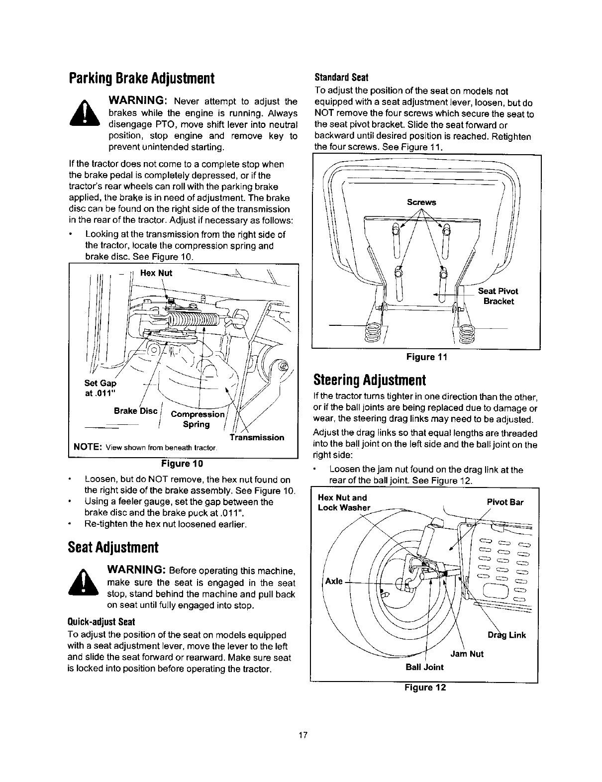
Looking at the transmission from the right side of
the tractor, locate the compression spring and
brake disc. See Figure 10.
Hex Nut _
Standard Seat
To adjust the position of the seat on models not
equipped with a seat adjustment lever, loosen, but do
NOT remove the four screws which secure the seat to
the seat pivot bracket. Slide the seat forward or
backward until desired position is reached. Retighten
the four screws. See Figure 11.
Screws
Seat Pivot
Bracket
Set Gap
at .011"
Brake Disc
Spring
NOTE: View shown from beneath tractor.
Transmission
Figure 10
Loosen, but do NOT remove, the hex nut found on
the right side of the brake assembly. See Figure 10.
Using a feeler gauge, set the gap between the
brake disc and the brake puck at .011".
Re-tighten the hex nut loosened earlier.
SeatAdjustment
AWARNING: Before operating this machine,
make sure the seat is engaged in the seat
stop, stand behind the machine and pull back
on seat until fully engaged intostop.
Quick-adjust Seat
To adjust the position of the seat on models equipped
with a seat adjustment lever, move the lever to the left
and slide the seat forward or rearward. Make sure seat
is locked into position before operating the tractor.
Figure 11
SteeringAdjustment
If the tractor turns tighter in one direction than the other,
or if the ball joints are being replaced due to damage or
wear, the steering drag links may need to be adjusted.
Adjust the drag links so that equal lengths are threaded
into the ball joint on the left side and the ball joint on the
right side:
Loosen the jam nut found on the drag link at the
rear of the ball joint. See Figure 12.
Hex Nut and Pivot Bar
Lock Washer
g Link
Jam Nut
Bali Joint
Figure 12
17
Remove the hex nut and lock washer on the top of
ball joint. See Figure 12.
Thread the ball joint toward the jam nut to shorten
the drag link. Thread the ball joint away from the
jam nut to lengthen the drag link.
Replace hex nut and lock washer and retighten the
jam nut after proper adjustment is achieved.
NOTE: Threading the ball joints too far onto the drag
links will cause the front tires to "toe-in" too far. Proper
toe-in is between 1/16" and 5/16".
Front tire toe-in can be measured as follows:
Place the steering wheel in position for straight
ahead travel.
In front of the axle, measure the distance
horizontally from the inside of the left rim to the
inside of the right rim. Note the distance.
Behind the axle, measure the distance horizontally
from the inside of the left rim to the inside of the
right rim. Note the distance.
The measurement taken in front of the axle should
be between 1/16" and 5/16" less than the
measurement taken behind the axle. Adjust if
necessary.
SECTION7: MAINTAININGYOURLAWNTRACTOR
WARNING: Before performing any
maintenance or repairs, disengage PTO,
move shift lever into neutral position, set
parking brake, stop engine and remove key to
prevent unintended starting.
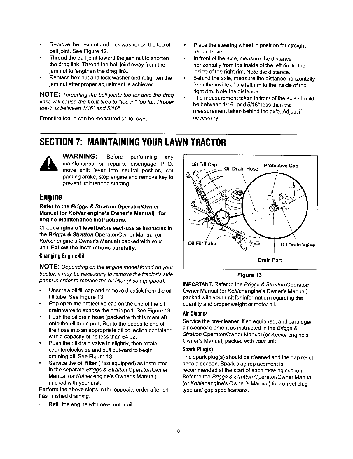
Oil Fill Cap Oil Drain Hose Protective Cap
Engine
Refer to the Briggs & Stratton Operator/Owner
Manual (or Kohlerengine's Owner's Manual) for
engine maintenance instructions.
Check engine oil level before each use as instructed in
the Briggs & Stratton Operator/Owner Manual (or
Koh/er engine's Owner's Manual) packed with your
unit. Follow the instructions carefully.
Changing Engine Oil
NOTE: Depending on the engine model found on your
tractor, it may be necessary to remove the tractor's side
panel in order to replace the oil filter (if so equipped).
Unscrew oil fill cap and remove dipstick from the oil
fill tube. See Figure 13.
Pop open the protective cap on the end of the oil
drain valve to expose the drain port. See Figure 13.
Push the oil drain hose (packed with this manual)
onto the oil drain port. Route the opposite end of
the hose into an appropriate oil collection container
with a capacity of no less than 64 oz.
Push the oil drain valve in slightly, then rotate
counterclockwise and pull outward to begin
draining oil. See Figure 13.
Service the oil filter (if so equipped) as instructed
in the separate Briggs & Stratton Operator/Owner
Manual (or Kohlerengine's Owner's Manual)
packed with your unit.
Perform the above steps in the opposite order after oil
has finished draining.
Refill the engine with new motor oil.
Oil Fill Tube Oil Drain Valve
Drain Port
Figure 13
IMPORTANT: Refer to the Briggs & Stratton Operator/
Owner Manual (or Kohler engine's Owner's Manual)
packed with your unit for information regarding the
quantity and proper weight of motor oil.
Air Cleaner
Service the pre-cleaner, if so equipped, and cartddge/
air cleaner element as instructed in the Briggs &
Stratton Operator/Owner Manual (or Kohler engine's
Owner's Manual) packed with your unit.
SparkPlug(s)
The spark plug(s) should be cleaned and the gap reset
once a season. Spark plug replacement is
recommended at the start of each mowing season.
Refer to the Briggs & Stratton Operator/Owner Manual
(or Kohler engine's Owner's Manual) for correct plug
type and gap specifications.
18
Lubrication
A
Engine
WARNING: Before lubricating, repairing, or
inspecting, always disengage PTO, move
shift lever into neutral position, set parking
brake, stop engine and remove key to prevent
unintended starting.
Lubricate the engine with motor oil as instructed in the
Briggs & Stratton Operator/Owner Manual (or Kohler
engine's Owner's Manual) packed with your unit.
Pivot Points & Linkage
Lubricate all the pivot points on the drive system,
parking brake and lift linkage at least once a season
with light oil.
Rear Wheels
The rear wheels should be removed from the axles
once a season. Lubricate the axles and the rims well
with an all-purpose grease before re-installing them.
FrontAxles
Each end of the tractor's front pivot bar may be
equipped with a grease fitting. Lubricate with a grease
gun after every 25 hours of tractor operation.
Cleaningthe EngineAndDeck
Any fuel or oil spilled on the machine should be wiped
off promptly. Do NOT allow debris to accumulate
around the cooling fins of the engine or on any other
part of the machine, especially the belts, pulleys and
other moving parts. Clean the underside of the deck
with a wisk broom, scraper or forced air after each
mowing.
IMPORTANT: The use of a pressure washer or garden
hose to clean your tractor is NOT recommended. It may
cause damage to electrical components, spindles,
pulleys, bearings or the engine. The use of water will
result in a shortened life of the tractor and reduce its
serviceability.
SECTION8: SERVICE
CuttingDeckRemoval
To remove the cutting deck, proceed as follows:
Place the PTO knob (or lever) in the disengaged
(OFF) position and engage the parking brake.
Lower the deck by moving the deck lift lever into the
bottom notch on the right fender.
On models equipped with a 42-inch deck, remove
the PTO belt from around the cutting deck's center
pulley. Refer to Figure 17.
On models equipped with a 46-inch deck, remove
the PTO belt from around the tractor's engine pulley
(or electric PTO clutch, if so equipped) and idler
pulley(s). Refer to Figure 18.
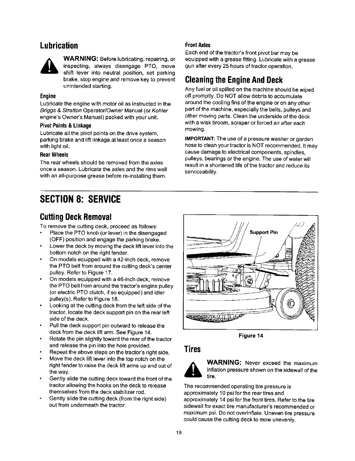
Looking at the cutting deck from the left side of the
tractor, locate the deck support pin on the rear left
side of the deck.
Pull the deck support pin outward to release the
deck from the deck lift arm. See Figure 14.
Rotate the pin slightly toward the rear of the tractor
and release the pin into the hole provided.
Repeat the above steps on the tractor's right side.
Move the deck lift lever into the top notch on the
right fender to raise the deck lift arms up and out of
the way.
Gently slide the cutting deck toward the front of the
tractor allowing the hooks on the deck to release
themselves from the deck stabilizer rod.
Gently slide the cutting deck (from the right side)
out from underneath the tractor.
Figure 14
Tires
WARNING: Never exceed the maximum
inflation pressure shown on the sidewall of the
tire.
The recommended operating tire pressure is
approximately 10 psi for the rear tires and
approximately 14 psi for the front tires. Refer to the tire
sidewall for exact tire manufacturer's recommended or
maximum psi. Do not overinflate. Uneven tire pressure
could cause the cutting deck to mow unevenly.
19
CuttingBlades
WARNING: Be sure to shut the engine off,
remove ignition key, disconnect the spark
plug wire(s) and ground against the engine to
prevent unintended starting before removing
the cutting blade(s) for sharpening or
replacement. Protect your hands by using
heavy gloves or a rag to grasp the cutting
blade.
AWARNING: Periodically inspect the blade
adapter and/or spindlefor cracks or damage,
especially if you strike a foreign object.
Replace immediatelyif damaged.
The blades may be removed as follows.
Remove the deck from beneath the tractor, (refer to
CuttingDeckRemovalon page 19) then gently flip the
deck over to expose its underside.
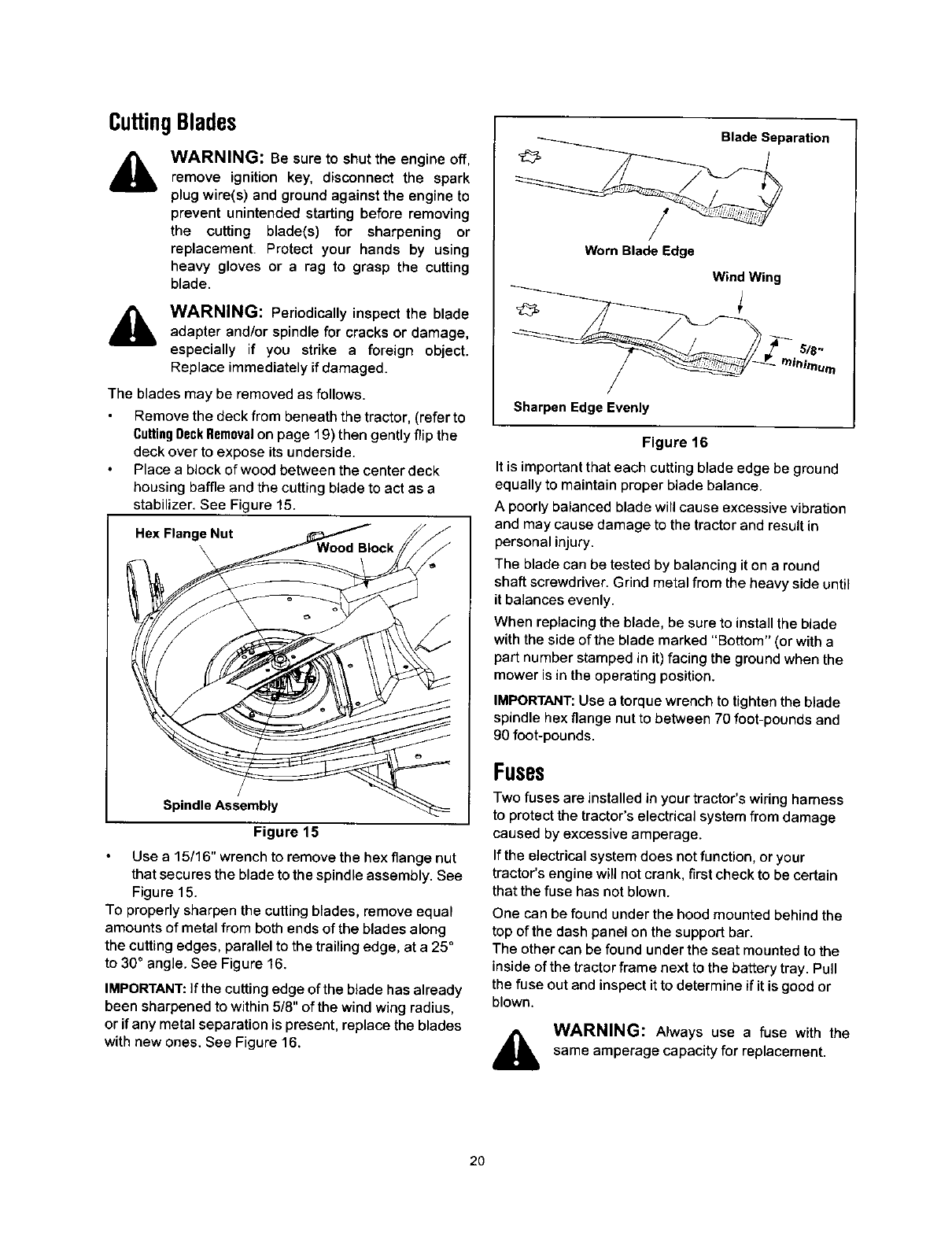
Place a block of wood between the center deck
housing baffle and the cutting blade to act as a
stabilizer. See Figure 15.
Hex Flange Nut
/
Spindle Assembly
Figure 15
Use a 15/16" wrench to remove the hex flange nut
that secures the blade to the spindle assembly. See
Figure 15.
To properly sharpen the cutting blades, remove equal
amounts of metal from both ends of the blades along
the cutting edges, parallel to the trailing edge, at a 25 °
to 30° angle. See Figure 16.
IMPORTANT: If the cutting edge of the blade has already
been sharpened to within 5/8" of the wind wing radius,
or ifany metal separation is present, replace the blades
with new ones. See Figure 16.
Blade Separation
/
Worn Blade Edge
Wind Wing
__ rnia#.um
Sharpen Edge Evenly
Figure 16
It is important that each cutting blade edge be ground
equally to maintain proper blade balance.
A poorly balanced blade will cause excessive vibration
and may cause damage to the tractor and result in
personal injury.
The blade can be tested by balancing it on a round
shaft screwdriver. Grind metal from the heavy side until
it balances evenly.
When replacing the blade, be sure to install the blade
with the side of the blade marked "Bottom" (or with a
part number stamped in it) facing the ground when the
mower is in the operating position.
IMPORTANT: Use a torque wrench to tighten the blade
spindle hex flange nut to between 70 foot-pounds and
90 foot-pounds.
Fuses
Two fuses are installed in your tractor's wiring hamess
to protect the tractor's electrical system from damage
caused by excessive amperage.
If the electrical system does not function, or your
tractor's engine will not crank, first check to be certain
that the fuse has not blown.
One can be found under the hood mounted behind the
top of the dash panel on the support bar.
The other can be found under the seat mounted to the
inside of the tractor frame next to the battery tray. Pull
the fuse out and inspect it to determine ifit is good or
blown.
WARNING: Always use a fuse with the
same amperage capacity for replacement.
2O
Changingthe DeckBelt& PT0 Belt
WARNING: Be sure to shut the engine off,
remove ignition key, disconnect the spark
plug wire(s) and ground against the engine to
prevent unintended starting before removing
the belt(s).
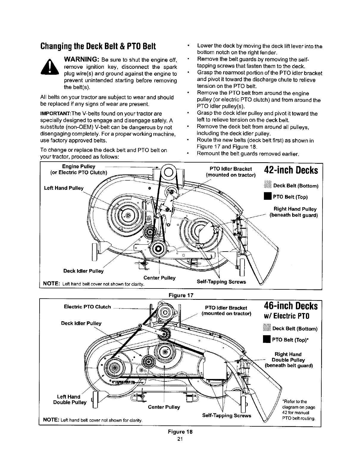
Lower the deck by moving the deck lift lever into the
bottom notch on the right fender.
Remove the belt guards by removing the self-
tapping screws that fasten them to the deck.
Grasp the rearmost portion of the PTO idler bracket
and pivot it toward the discharge chute to relieve
tension on the PTO belt.
Remove the PTO belt from around the engine
pulley (or electric PTO clutch) and from around the
PTO idler pulley(s).
Grasp the deck idler pulley and pivot it toward the
left to relieve tension on the deck belt.
Remove the deck belt from around all pulleys,
including the deck idler pulley.
Route the new belts (deck belt first) as shown in
Figure 17 and Figure 18.
Remount the belt guards removed earlier.
A
All belts on your tractor are subject to wear and should
be replaced if any signs of wear are present.
IMPORTANT:The V-belts found on your tractor are
specially designed to engage and disengage safely, A
substitute (non-OEM) V-belt can be dangerous by not
disengaging completely. For a proper working machine,
use factory approved belts.
To change or replace the deck belt and PTO belt on
our tractor, proceed as follows:
Engine Pulley
(or Electric PTO Clutch)
Left Hand Pulley
PTO Idler Bracket 42-inchDecks
)
Deck Belt (Bottom)
•PTO Belt (Top)
Right Hand Pulley
(beneath belt guard)
Deck Idler Pulley
Center Pulley
NOTE: Left hand belt cover not shown for clarity. Self-Tapping Screws
Electric PTO Clutch
Deck idler Pulley
Figure 17
PTO Idler Bracket
(mounted on tractor)
46-inchDecks
w/Electric PT0
Deck Belt (Bottom)
•PTO Belt (Top)*
Right Hand
Double Pulley
guard)
Left Hand
Double Pulley
NOTE: Left hand belt cover not shown for clarity.
Center Pulley
\
Self-TappingScrews
Figure 18
21
'Refer to the
diagram on page
42 for manual
PTO belt routing.

Variable-speed Battery Tray
Pulley_ Opening Shin Lever
Rear Idler Pulley
Drive belt (Lower)
mDrive belt (Upper)
II
Single-speed ...... _-
Transmission Transmission Pulley
NOTE: View shown from above tractor.
I r
Double-Idler Bracket _--- _' /i
Transmission Idler Pulley
Front of Tractor
Engine Pulley
Figure 19
ChangingtheTransmissionDriveBelt
AWARNING: Be sure to shut the engine off,
remove ignition key, disconnect the spark
plug wire(s) and ground against the engine to
prevent unintended starting before removing
the belt(s)
All belts on your tractor are subject to wear and should
be replaced if any signs of wear are present.
IMPORTANT: The V-belts found on your tractor are
specially designed to engage and disengage safely. A
substitute (non-OEM) V-belt can be dangerous by not
disengaging completely. For a proper working machine,
use factory approved belts.
To change or replace the drive belt on your tractor,
proceed as follows:
Remove the cutting deck as instructed earlier in this
section.
After disconnecting the battery cables, remove the
battery and battery tray from beneath the seat.
IMPORTANT: When removing the battery, disconnect
the NEGATIVE (Black) wire from it's terminal first,
followed by the POSITIVE (Red) wire. Re-install in
reverse order.
Upper Drive Belt
Locate the transmission idler pulley on the upper
drive belt by looking through the battery tray
opening. See Figure 19.
Grasp the bracket and pivot the transmission idler
pulley toward the rear of the tractor to release
tension on the upper drive belt.
Remove the belt from around the transmission idler
pulley.
Remove the upper drive belt from around the
transmission pulley and the variable-speed pulley.
NOTE: Slowly rotate the pulley counterclockwise to
re/I the belt off of it.
Remove the upper drive belt by pulling it up through
the battery tray opening.
Rereute the new upper drive belt as shown in
Figure 19.
22
LowerDriveBelt
NOTE: Proper removal of the lower drive belt requires
the removal of several tractor components. Read
through the following procedure prior to attempting ff to
determine if you feel you could successfully complete it.
If you don't, see an authorized MTD service dealer to
have the belt changed.
IMPORTANT: Note the routing of the lower drive belt
around all the pulleys and the belt keepers BEFORE
performing the following steps.
Locate the variable-speed pulley through the
battery tray opening. See Figure 19.
Remove the variable-speed pulley by loosening the
hex bolt that secures it to the transmission. Use a
second wrench to hold the hex nut on the bottom
side of the pulley.
Slide the lower drive belt off of the varia ble-speed
pulley as you lift the pulley up and out through the
battery tray opening.
Remove the rear idler pulley from the double- idler
bracket while unrouting the belt from around both
the rear and the front idler pulley. Refer to Figure
19.
Remove the hex bolt from the center of the engine
pulley (or electric PTO clutch, if so equipped) and
gently lower it off of the engine crankshaft. Be
careful not to lose any washers or spacers which
may be found on top of the engine pulley.
IMPORTANT: When remounting the engine pulley (or
electric PTO clutch), torque the center hex bolt to
between 38 foot-pounds and 50 foot-pounds.
Remove the drive belt by feeding it from both ends
toward the front idler pulley on the double-idler
bracket. See Figure 19.
Reassemble by following the above steps in
reverse order.
Route the replacement belt around the pulleys, belt
keepers and keeper pins EXACTLY as the old one
was routed. Refer to Figure 19.
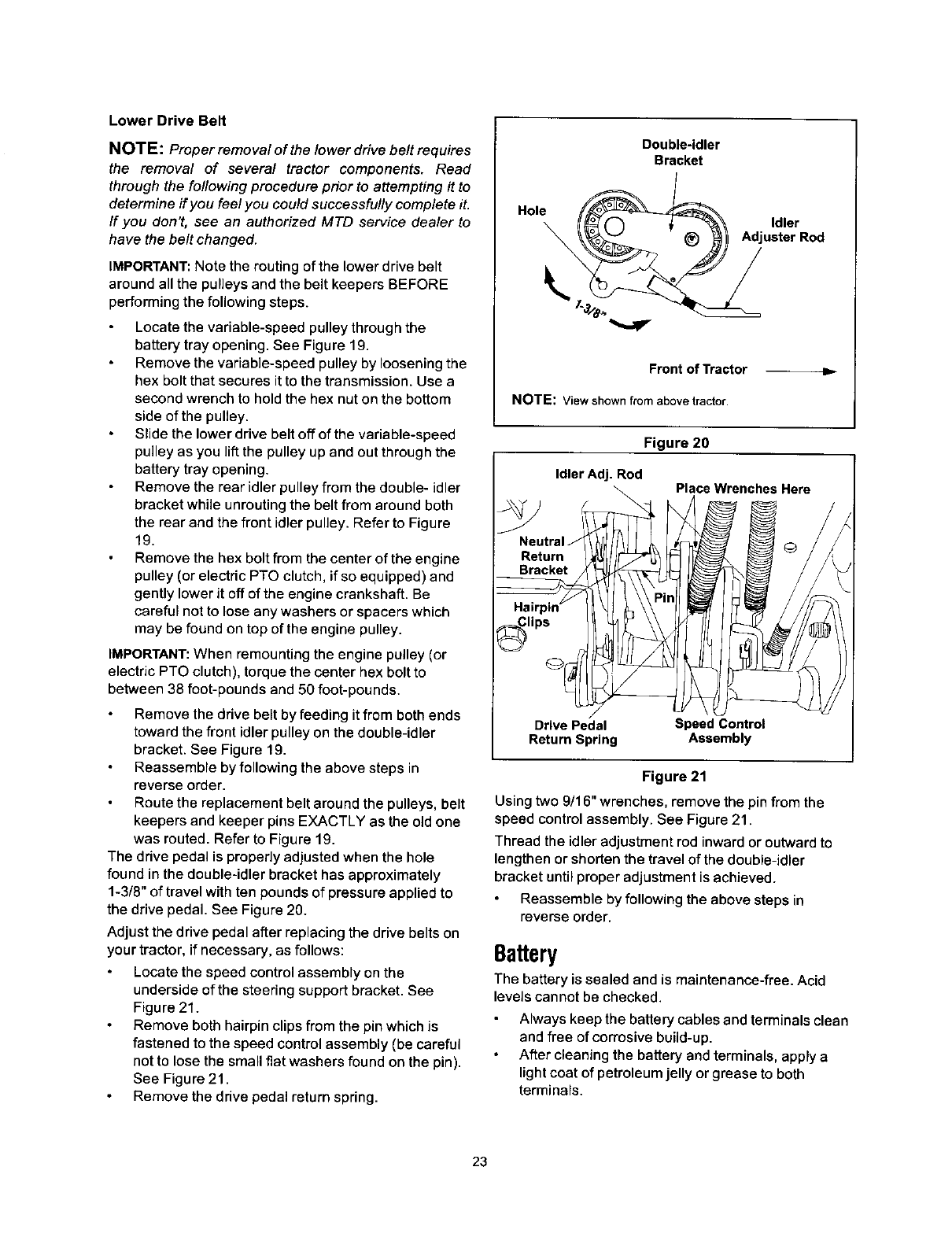
The drive pedal is properly adjusted when the hole
found in the double-idler bracket has approximately
1-3/8" of travel with ten pounds of pressure applied to
the drive pedal. See Figure 20.
Adjust the drive pedal after replacing the drive belts on
your tractor, if necessary, as follows:
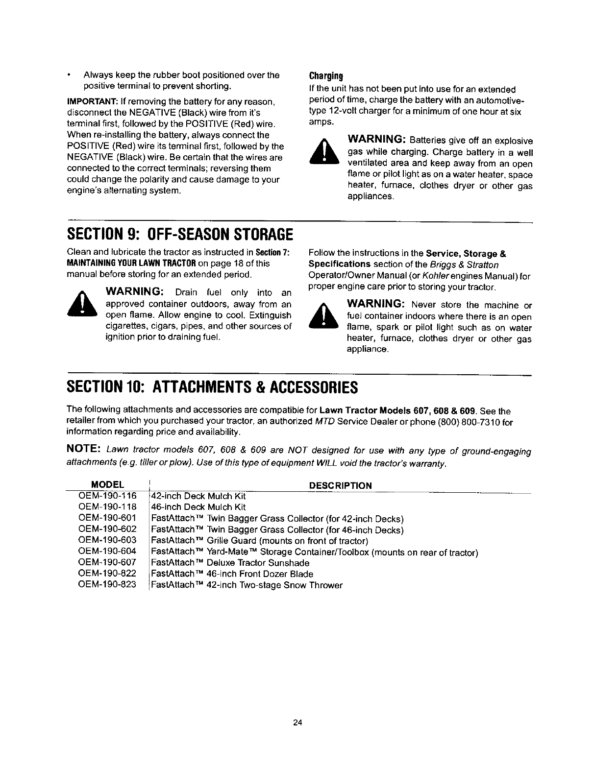
Locate the speed control assembly on the
underside of the steering support bracket. See
Figure 21.
Remove both hairpin clips from the pin which is
fastened to the speed control assembly (be careful
not to lose the small flat washers found on the pin).
See Figure 21.
Remove the drive pedal return spring.
Double-idler
Bracket
Hole _AdjuldlerrRod
Front of Tractor
NOTE: Viewshownfrom abovetractor.
Figure 20
Idler Adj. Rod
\
Neutral J
Return
Bracket
lips
Drive Pedal Speed Control
Return Spring Assembly
Place Wrenches Here
Figure 21
Using two 9/16" wrenches, remove the pin from the
speed control assembly. See Figure 21.
Thread the idler adjustment rod inward or outward to
lengthen or shorten the travel of the double-idler
bracket until proper adjustment is achieved.
Reassemble by following the above steps in
reverse order.
Battery
The battery is sealed and is maintenance-free. Acid
levels cannot be checked.
Always keep the battery cables and terminals clean
and free of corrosive build-up.
After cleaning the battery and terminals, apply a
light coat of petroleum jelly or grease to both
terminals.
23
Alwayskeeptherubberbootpositionedoverthe
positiveterminaltopreventshorting.
IMPORTANT:If removing the battery for any reason,
disconnect the NEGATIVE (Black) wire from it's
terminal first, followed by the POSITIVE (Red) wire.
When re-installing the battery, always connect the
POSITIVE (Red) wire its terminal first, followed by the
NEGATIVE (Black) wire. Be certain that the wires are
connected to the correct terminals; reversing them
could change the polarity and cause damage to your
engine's aflernating system.
Charging
If the unit has not been put into use for an extended
period of time, charge the battery with an automotive-
type 12-voU charger for a minimum of one hour at six
amps.
AWARNING: Batteries give off an explosive
gas while charging. Charge battery in a well
ventilated area and keep away from an open
flame orpilotlightas ona water heater, space
heater, furnace, clothes dryer or other gas
appliances.
SECTION9: OFF-SEASONSTORAGE
Clean and lubricate the tractor as instructed in Section7:
MAINTAININGYOURLAWNTRACTORon page 18 of this
manual before storing for an extended period.
AWARNING: Drain fuel only into an
approved container outdoors, away from an
open flame. Allow engine to cool. Extinguish
cigarettes, cigars, pipes, and other sources of
ignition prior to draining fuel.
Follow the instructions in the Service, Storage &
Specifications section of the Briggs &Stratton
Operator/Owner Manual (or Koh/er engines Manual) for
proper engine care prior to storing your tractor.
AWARNING: Never store the machine or
fuel container indoors where there is an open
flame, spark or pilot light such as on water
heater, furnace, clothes dryer or other gas
appliance.
SECTION10: ATTACHMENTS& ACCESSORIES
The following attachments and accessories are compatible for Lawn Tractor Models 607, 608 & 669. See the
retailer from which you purchased your tractor, an authorized MTD Service Dealer or phone (800) 800-7310 for
information regarding price and availability.
NOTE: Lawn tractor models 607, 608 & 609 are NOT designed for use with any type of ground-engaging
attachments (e.g. ti/ler or plow). Use of this type of equipment WILL void the tractor's warranty.
MODEL
OEM-190-116
OEM-190-118
OEM-190-601
OEM-190-602
OEM-190-603
OEM-190-604
OEM-190-607
OEM-190-822
OEM-190-823
DESCRIPTION
42-inch Deck Mulch Kit
46-inch Deck Mulch Kit
FastAttach TM Twin Bagger Grass Collector (for 42-inch Decks)
FastAttach TM Twin Bagger Grass Collector (for 46-inch Decks)
FastAttach TM Grille Guard (mounts on front of tractor)
FastAttach TM Yard-Mate TM Storage Container/Toolbox (mounts on rear of tractor)
FastAttach TM Deluxe Tractor Sunshade
FastAttach TM 46-inch Front Dozer Blade
FastAttach TM 42-inch Two-stage Snow Thrower
24
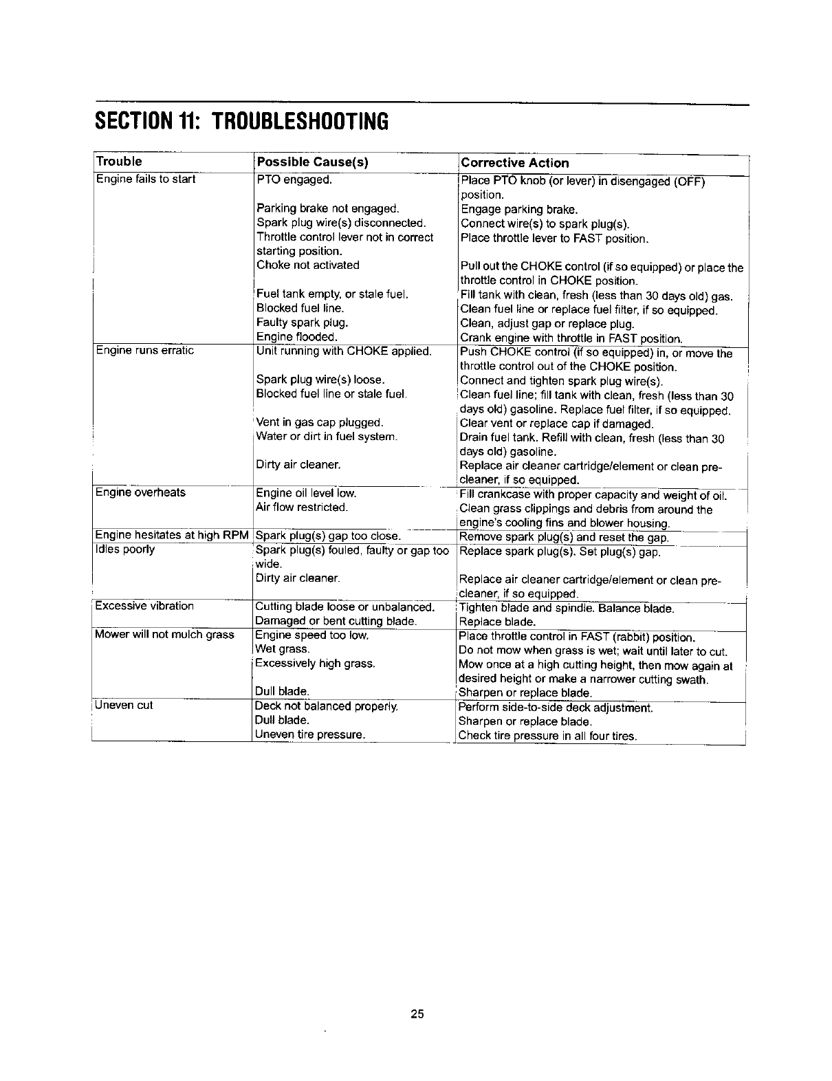
SECTION11:TROUBLESHOOTING
Trouble
Eng ne fa s to start
Engine runs erratic
Engine overheats
Possible Cause(s) Corrective Action
PTO engaged.
Parking brake not engaged.
Spark plug wire(s) disconnected.
Throttlecontrol lever not in correct
starting position.
Choke not activated
I
Fuel tank empty, or stale fuel.
Blocked fuel line.
Faulty spark plug.
Engine flooded.
Unit running with CHOKE applied.
Place PTO knob (or lever) in disengaged (OFF)
position.
Engage parking brake.
Connect wire(s) to spark plug(s).
Place throttle lever to FAST position.
Pull out the CHOKE control (if so equipped) or place the
throttle control in CHOKE position.
Fill tank with clean, fresh (less than 30 days old) gas.
Clean fuel line or replace fuel filter, if so equipped.
Clean, adjust gap or replace plug.
Crank engine with throttle in FAST position.
Push CHOKE control (if so equipped) in, or move the
Ithrottlecontrol out of the CHOKE position.
Spark plug wire(s) loose. ,Connect and tighten spark plug wire(s).
Blocked fuel line or stale fuel. Clean fuel line; fill tank with clean, fresh (less than 30
,days old) gasoline. Replace fuel filter, if so equipped.
'Vent in gas cap plugged. Clear vent or replace cap if damaged.
iWater or dirt in fuel system. Drain fuel tank. Refill with clean, fresh (less than 30
Engine oil level low. days old) gasoline.
Dirty air cleaner. Rep ace air cleaner cartridge/element or clean pre-
Icleaeer, if so equipped.
Fill crankcase with proper capacity and weight of oil.
Clean grass clippings and debris from around the
A r f ow restricted. _ engine's cooling fins and blower housing.
Engine hesitates at high RPM_Spark plug(s) gap oo c ose _Rer:n_) an_l_egap.
Idles poorly !Spark plug(s) fouled, faulty or gap too IReplace spark plug(_). Setplug(_ i gapZ
wide. /
Replace air cleaner cartridge/element or clean
Dirty air cleaner, pre-
Cutting blade loose or unbalanced. !cleaner, if so equipped.
Excessive vibration 'Tighten blade and spindle. Balance blade.
Damaged or bent cutting blade. R__pfaceblade.
Mower will not mulch grass Engine speed too low. Place throttle control in FAST (rabbit) position.
Wet grass. Donot mow when grass is wet; wait until later to cut.
Excessively high grass. Mow once at a high cutting height, then mow again at
desired height or make a narrower cutting swath.
Dull blade. :Sharpen or replace blade.
Uneven cut Deck not balanced properly Perform side-to-side deck adjustment.
Dull blade. Sharpen or replace blade.
Uneven tire pressure. Check tire pressure in all four tires.
25

SECTION12: MODELS607, 608 & 609 PARTSLIST
B&S OHV V-Twin B&S OpposedTwin
33
S (for throttle)
j 28 (forstartercable)
t
B&SOHVSingle
j_
Kohler
j 14 (deflectormust
J face forward)
42
45
28
lO
5
35
41
40
37
26
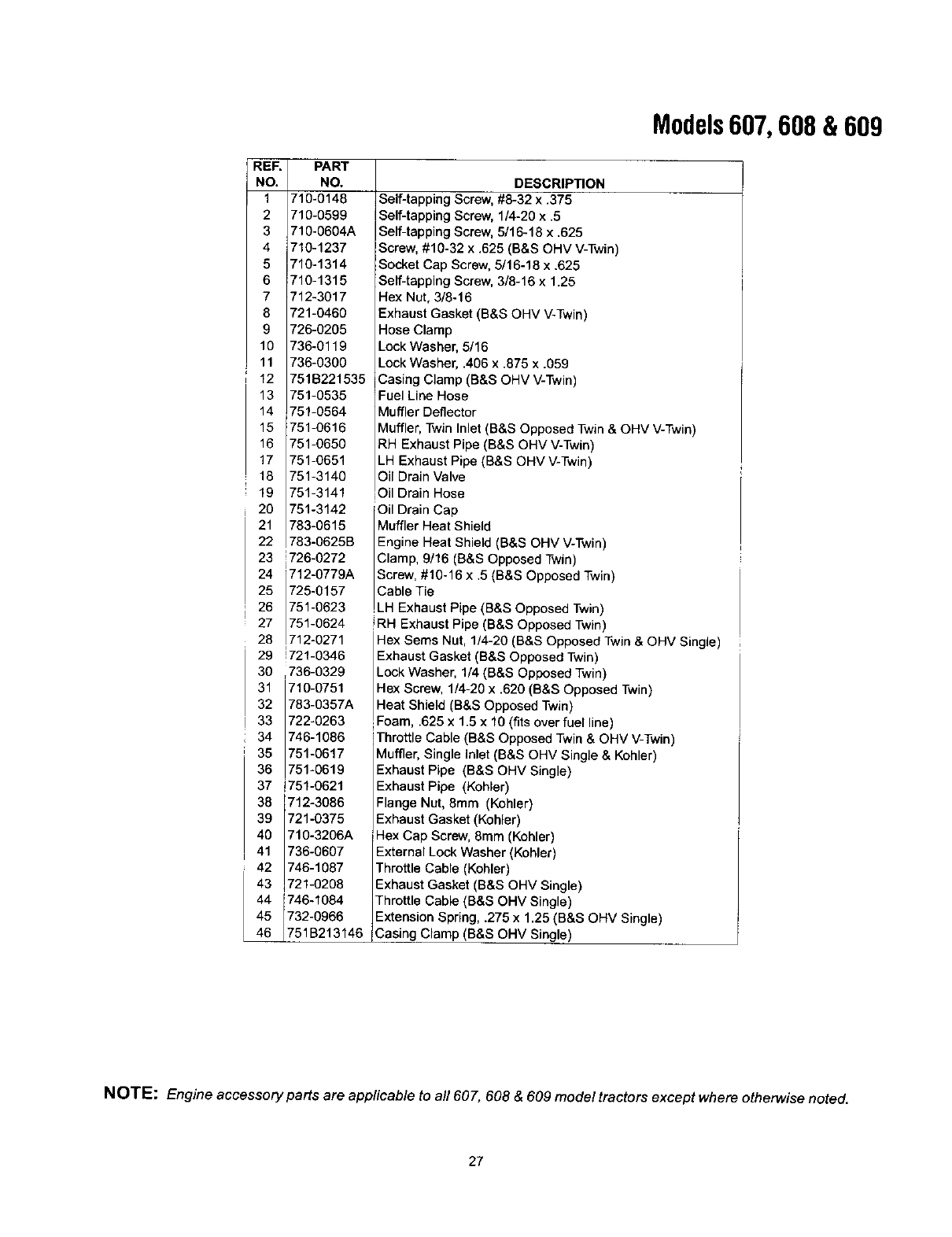
REF.
NO.
1
2
3
4
5
6
7
8
9
10
11
12
PART
NO.
716-0148
710-0599
710-0604A
710-1237
710-1314
710-1315
712-3017
721-0460
726-0205
736-0119
736-0300
751B221535
13 751-0535
14 751-0564
15 751-0616
16 751-0650
17 751-0651
18 751-3140
19 751-3141
20 751-3142
21 783-0615
22 783-0625B
23 726-0272
24 712-0779A
25 725-0157
26 751-0623
27 751-0624
28 712-0271
29 1721-0346
30 ,736-0329
31 710-0751
32 783-0357A
33 722-0263
34 746-1086
35 751-0617
36 751-0619
37 i751-0621
38 712-3086
39 721-0375
40 710-3206A
41 736-0607
42 746-1087
43 721-0208
44 746-1084
45 732-0966
46 751B213146
Models607, 608 &609
DESCRIPTION
Serf-tapping Screw, #8-32 x,375
Self-tapping Screw, 1/4-20 x .5
Self-tappingScrew, 5/16-18 x .625
Screw, #10-32 x .625 (B&S OHV V-Twin)
Socket Cap Screw,5/16-16 x .625
Self-tappingScrew, 3/8-16 x 1.25
Hex Nut, 3/8-16
Exhaust Gasket (B&S OHV V-Twin)
Hose Clamp
Lock Washer, 5/16
Lock Washer, .406 x .875 x .059
Casing Clamp (B&S OHV V-Twin)
Fuel Line Hose
Muffler Deflector
Muffler,Twin Inlet (B&S Opposed Twin& OHV V-Twin)
RH Exhaust Pipe (B&S OHV V-Twin)
LH Exhaust Pipe (B&S OHV V-Twin)
Oil Drain Valve
Oil Drain Hose
Oil Drain Cap
Muffler Heat Shield
Engine Heat Shield (B&S OHV V-Twin)
Clamp, 9/16 (B&S Opposed Twin)
Screw, #10-16 x .5 (B&S Opposed Twin)
Cable Tie
LH Exhaust Pipe (B&S Opposed Twin)
RH Exhaust Pipe (B&S Opposed Twin)
Hex Sems Nut, 1/4-20 (B&S Opposed Twin & OHV Single)
Exhaust Gasket (B&S Opposed Twin)
LockWasher, 1/4 (B&S Opposed Twin)
Hex Screw, 1/4-20 x .620 (B&S Opposed Twin)
Heat Shield (B&S Opposed Twin)
Foam, .625 x 1.5 x 10 (fits overfue ne)
ThrottleCable (B&S Opposed Twin& OHV V-Twin)
Muffler,Single Inlet (B&S OHV Single & Kohler)
Exhaust Pipe (B&S OHV Single)
Exhaust Pipe (Kohler)
Flange Nut, 8ram (Kohler)
Exhaust Gasket (Kohler)
Hex Cap Screw, 8mm (Kohlar)
External Lock Washer (Kohler)
Throttle Cable (Kohler)
Exhaust Gasket (B&S OHV Single)
Throttle Cable (B&S OHV Single)
Extension Spring, .275 x 1.25 (B&S OHV Single)
Casing Clamp (B&S OHV Single)
NOTE; Engine accessory parts are applicable to all 607, 608 & 609 model tractors except where otherwise noted.
27
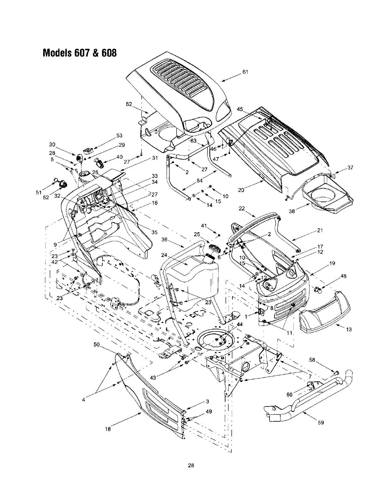
Models607 & 608
62
3O
5_
51
\
18
;I
22
44
38
_. 58
59
28
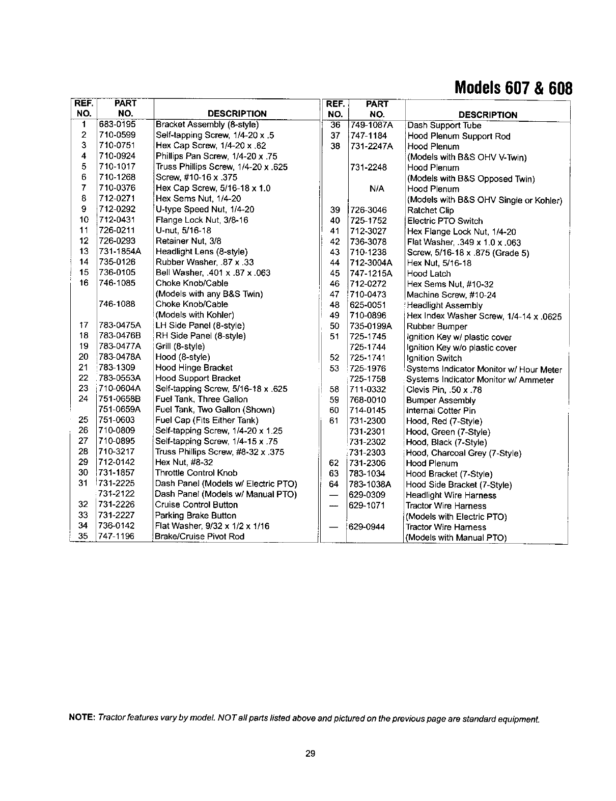
REF. PART
NO. NO.
1 583-0195
2 710-0599
3 710-0751
4 710-0924
5 710-1017
6 710-1268
7 710-9376
8 712-0271
9712-0292
10 712-0431
11 726-0211
12 726-0293
13 731-1854A
14 735-0126
15 736-0105
16 746-1085
746-1088
17 783-0475A
18 783-0476B
19 783-0477A
20 783-0478A
21 783-1309
22 783-0553A
23 710-0604A
24 751-0658B
751-0659A
25 751-0603
26 710-0809
27 710-0895
28 710-3217
29 712-0142
30 731-1857
31 _731-2225
i731-2122
32 731-2226
33 731-2227
34 736-0142
__35 747-1196
DESCRIPTION
Bracket Assembly (8-style)
Self-tapping Screw, 1/4-20 x .5
Hex Cap Screw, 1/4-20 x .62
Phillips Pan Screw, 1/4-20 x .75
Truss Phillips Screw, 1/4-20 x .625
Screw, #10-16 x .375
Hex Cap Screw, 5/16-18 x 1.0
Hex Sems Nut, 1/4-20
U-type Speed Nut, 1/4-20
Flange Lock Nut, 3/8-16
U-nut, 5/16-18
Retainer Nut, 3/8
Headlight Lens (8-style)
Rubber Washer, .87 x .33
Bell Washer, .401 x .87 x .063
Choke Knob/Cable
(Models with any B&S Twin)
Choke Knob/Cable
Models with Kohler)
iLH Side Panel (8-style)
IRH Side Panel (8-style)
Grill (8-style)
Hood (8-style)
Hood Hinge Bracket
Hood Support Bracket
Self-tapping Screw, 5/16-18 x .625
Fuel Tank, Three Gallon
Fuel Tank, Two Gallon (Shown)
Fuel Cap (Fits Either Tank)
!Self-tapping Screw, 1/4-20 x 1.25
Self-tapping Screw, 1/4-15 x .75
TrussPhillips Screw, #8-32 x .375
Hex Nut, #8-32
Throttle Control Knob
Dash Panel (Models w/Electric PTO)
Dash Panel (Models w/Manual PTO)
Cruise Control Button
Parking Brake Button
Flat Washer, 9/32 x 1/2 x 1/16
Brake/Cruise Pivot Rod
REF.
NO.
36
37
38
39
40
41
42
43
44
45
46
47
48
49
5O
51
52
53
I58
59
60
61
62
63
64
Models607 & 608
PART
NO.
749-1087A
747-1184
731-2247A
731-2248
N/A
726-3046
725-1752
712-3027
736-3078
710-1238
712-3004A
747-1215A
712-0272
710-0473
625-0051
710-0896
735-0199A
725-1745
725-1744
725-1741
725-1976
i725-1758
711-0332
768-0010
714-0145
731-2300
731-2301
!731-2302
731-2303
731-2306
783-1034
783-1038A
629-0309
629-1071
629-0944
DESCRIPTION
Dash Support Tube
Hood PlenumSupport Rod
Hood Plenum
(Models with B&S OHV V-Twin)
Hood Plenum
(Models with B&S Opposed Twin)
Hood Plenum
(Models with B&S OHV Single or Kohler)
Ratchet Clip
Electric PTO Switch
Hex Flange Lock Nut, 1/4-20
Flat Washer, .349 x 1.0 x .063
Screw, 5/16-18 x .875 (Grade 5)
Hex Nut, 5/16-18
Hood Latch
Hex Sems Nut, #10-32
Machine Screw, #10-24
Headlight Assembly
Hex Index Washer Screw, 1/4-14 x .0625
Rubber Bumper
Ignition Keyw/plastic cover
Ignition Key w/o plastic cover
Ignition Switch
Systems Indicator Monitor w/Hour Meter
Systems Indicator Monitor w/Ammeter
Clevis Pin, .50 x .78
Bumper Assembly
Internal Cotter Pin
Hood, Red (7-Style)
Hood, Green (7-Style)
Hood, Black (7-Style)
Hood, Charcoal Grey (7-Style)
Hood Plenum
Hood Bracket (7-Style)
Hood Side Bracket (7-Style)
Headlight Wire Harness
Tractor Wire Harness
(Models with Electric PTO)
Tractor Wire Harness
(Models with Manual PTO)
NOTE: Tractor features vary by model NOT all parts listed above and pictured on the previous page are standard equipment.
29
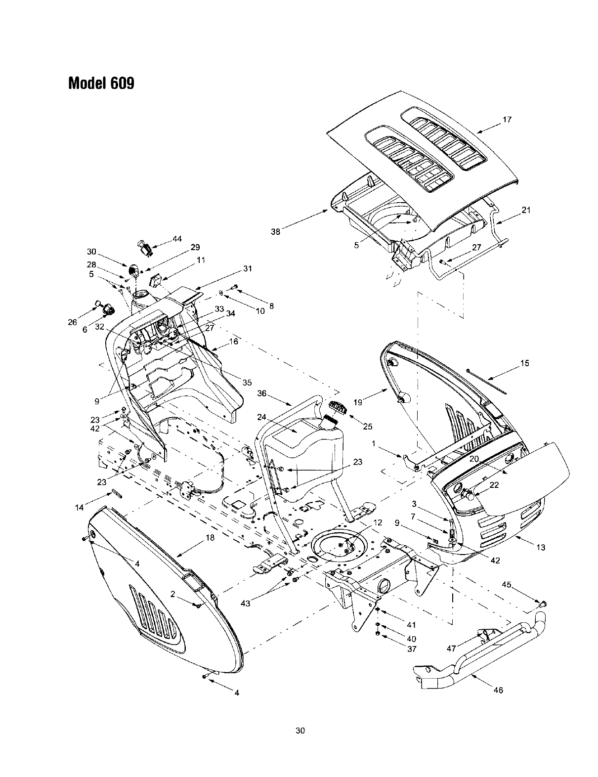
Model609
28_
5
26
27 - •
"8
r_. •
17
21
>
13
J
!
46
30
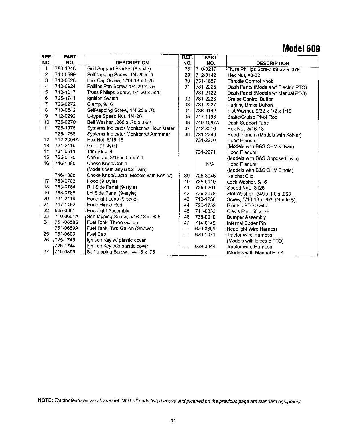
REF.
NO,
1
2
3
4
5
6
7
8
9
10
11
12
13
14
15
16
PART
NO.
783-1346
710-0599
710-0528
710-0924
710-1017
725-1741
726-0272
710-0642
712-0292
736-0270
725-1976
725-1758
712-3004A
731-2119
731-0511
725-0175
746-1085
!746-1088
17 783-0783
18 783-0784
19 783-0785
20 731-2119
21 747-1162
22 625-0051
23 710-0604A
24 751-0658B
751-0659A
25 751-0603
26 ,725-1745
725-1744
27 710-0895
DESCRIPTION
Grill Support Bracket (9-style)
Self-tapping Screw, 1/4-20 x .5
Hex Cap Screw, 5/16-18 x 1.25
PhillipsPan Screw, 1/4-20 x .75
TrussPhillipsScrew, 1/4-20 x .625
IgnitionSwitch
Clamp, 9/16
Self-tapping Screw, 1/4-20 x .75
U-type Speed Nut, 1/4-20
BellWasher, .265 x .75 x .062
Systems IndicatorMonitorw/Hour Meb
Systems indicator Monitorw/Ammeter
Hex Nut, 5/16-18
Grille (9-style)
Trim Strip, 4
Cable Tie, 3/16 x .05 x 7.4
Choke Knob/Cable
(Models with any B&S Twin)
Choke Knob/Cable (Models with Kohler)
Hood (9-style)
RH Side Panel (9-style)
LH Side Panel (9-style)
Headlight Lens (9-style)
!Hood Hinge Rod
Headlight Assembly
Self-tapping Screw, 5/16-18 x .625
Fuel Tank, Three Gallon
Fuel Tank, Two Gallon (Shown)
Fuel Cap
Ignition Key w/plastic cover
Ignition Key w/o plastic cover
Self-tapping Screw, 1/4-15 x .75
REF.
NO.
28
29
30
31
32
33
34
35
36
37
38
Model609
PART
NO.
710-3217
712-0142
731-1857
731-2225
731-2122
731-2226
731-2227
736-0142
747-1196
749-1087A
712-3010
731-2269
731-2270
731-2271
N/A
39 726-3046
40 736-0119
41 726-0201
42 736-3078
43 710-1238
44 728-1752
45 711-0332
46 768-0010
47 714-0145
-- 629-0309 !Headlight Wire Harness
-- 629-1071 Tractor Wire Harness
(Models with Electric PTO)
Tractor Wire Harness
629-0944 (Mode s wth Manual PTO)
DESCRIPTION
TrussPhillips Screw, #8-32 x.375
Hex Nut, #8-32
Throttle Control Knob
Dash Panel (Models w/Electric PTO)
Dash Panel (Models w/Manual PTO)
Cruise Control Button
Parking Brake Button
Flat Washer, 9/32 x 1/2 x 1/16
Brake/Cruise Pivot Rod
Dash Support Tube
Hex Nut, 5/16-18
Hood Plenum (Models withKohler)
Hood Plenum
(Models with B&S OHV V-Twin)
Hood Plenum
(Models with B&S Opposed Twin)
Hood Plenum
(Models with B&S OHV Single)
Ratchet Clip
LockWasher, 5/16
!Speed Nut, .3125
Flat Washer, .349 x 1.0 x .063
Screw, 5/16-16 x .875 (Grade 5)
ElectricPTO Switch
Clevis Pin, .50 x .78
BumperAssembly
nterna Cotter Pin
NOTE: Tractor featuresvary by model. NO Tall parts fisted above and pictured on the previous page are standard equipment.
31
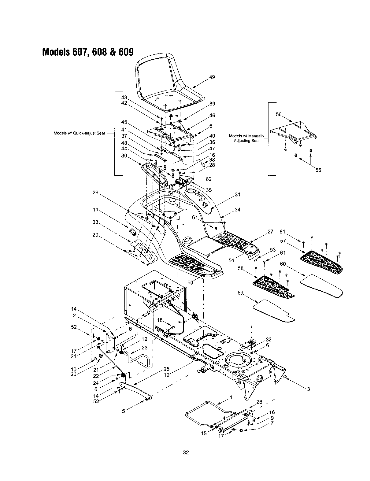
Models607, 608 & 609
Models w/( Models w! Manually
Adjusting Seat
55
35
_31
34
27 61
57_.
50
51
32
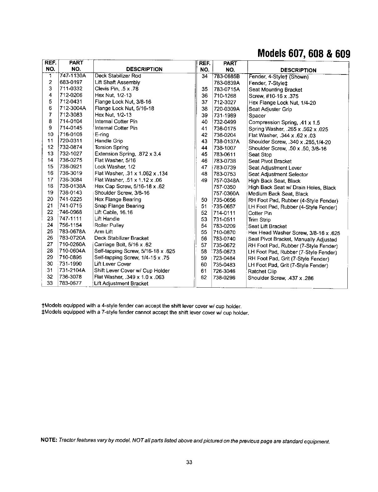
_E_ PART
_O. NO.
1 747-1130A
2 683-0197
3 711-0332
4 712-0206
5 712-0431
6 712-3004A
7 712-3083
8 714-0104
9 714-0145
10 716-0106
11 720-0311
12 732-6874
13 732-1027
14 736-0275
15 736-0921
16 736-3019
17 736-3084
18 738-0136A
19 738-0143
20 741-6225
21 741-0715
22 W46-0968
23 747-1111
24 756-1154
25 783-0678A
26 783-0726A
27 710-0260A
28 710-6604A
29 !710-0895
30 i731-1990
31 731-2104A
32 736-3078
p 33 783-0677
DESCRIPTION
Deck Stabilizer Rod
Lift Shaft Assembly
Clevis Pie, .5 x .78
Hex Nat, 1/2-13
Flange Lock Nut, 3/8-16
Flange Lock Nut, 5/16-18
Hex Nut, 1/2-13
Internal Cotter Pin
!Internal Cotter Pin
E-ring
Handle Grip
Torsion Spring
Extension Spring, .872 x 3.4
Flat Washer, 5/16
Lock Washer, 1/2
Flat Washer, .31 x 1.062 x .134
Flat Washer, .51 x 1.12 x .06
Hex Cap Screw, 5/16-18 x .62
iShoulder Screw, 3/8-16
Hex Flange Bearing
Snap Flange Bearing
Lift Cable, 16.16
Lift Handle
Re er Pu ey
Arm Lift
Deck Stabilizer Bracket
Carriage Bolt, 5/16 x .62
Self-tapping Screw, 5/16-18 x .625
Self-tapping Screw, 1/4-15 x .75
Lift Lever Cover
Shift Lever Cover w/Cup Holder
IFlat Washer .349 x 1.0 x .063
iLiftAdjustment Bracket
REF
NO.
34
PART
NO.
783-0685B
783-0839A
35 783-0715A
36 710-1268
37 712-3027
38 i720-0309A
39 731-1989
40 1732-0499
41 736-0175
42 736-0204
43 738-0137A
44 738-1007
45 783-0611
46 783-0738
47 i783-0739
48 783-0753
49 757-0348A
757-0350
757-0360A
50 735-0656
51 W35-0657
52 714-0111
53 731-0511
54 783-0209
55 710-0870
56 783-0740
57 735-0672
58 W35-0673
59 723-0484
60 735-0483
61 726-3046
62 738-0296
Models607, 608 & 609
DESCRIPTION
Fender, 4-Styler (Shown)
Fender, 7-Style_
Seat MountingBracket
Screw,#10-16 x .375
Hex Flange Lock Nut, 1/4-20
Seat Adjuster Grip
Spacer
Compression Spring, .41 x 1.5
Spring Washer, .265 x .562 x .025
Flat Washer, .344 x .62 x .03
Shoulder Screw,.340 x .285,1/4-20
Shoulder Screw, .50 x .50, 3/8-16
Seat Stop
Seat Pivot Bracket
Seat Adjustment Lever
Seat Adjustment Selector
H gh Back Seat, Black
]High Back Seat w/Drain Holes, Black
iMadium Back Seat, Black
RH FootPad, Rubber (4-Style Fender)
LH Foot Pad, Rubber(4-Style Fender)
Cotter Pin
ITrimStrip
ISeat LiftBracket
Hex Head Washer Screw, 3/5-16 x .625
Seat Pivot Bracket, Manually Adjusted
RH Foot Pad, Rubber (7-Style Fender)
LH Foot Pad, Rubber (7-Style Fender)
RH Foot Pad, Grit (7-Style Fender)
LH Foot Pad, Grit (7-Style Fender)
Ratchet Clip
Shoulder Screw, .437 x .286
tModels equipped witha4-style fender can accept the shiftlever cover w/cup holder.
_Models equipped witha 7-style fender cannot accept the shiftlever coverw/cup holder.
NOTE: Tractor features vary by model. NOT all parts listed above and pictured on the previous page are standard equipment.
33
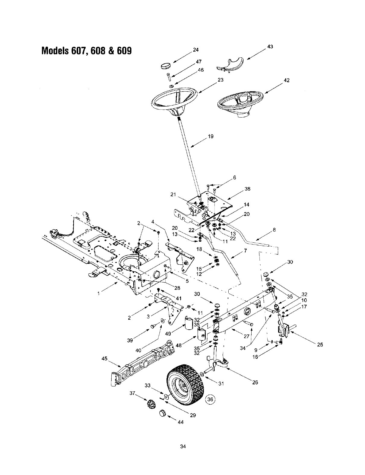
Models607, 608 & 609
132
27
_ 25
45
33
34
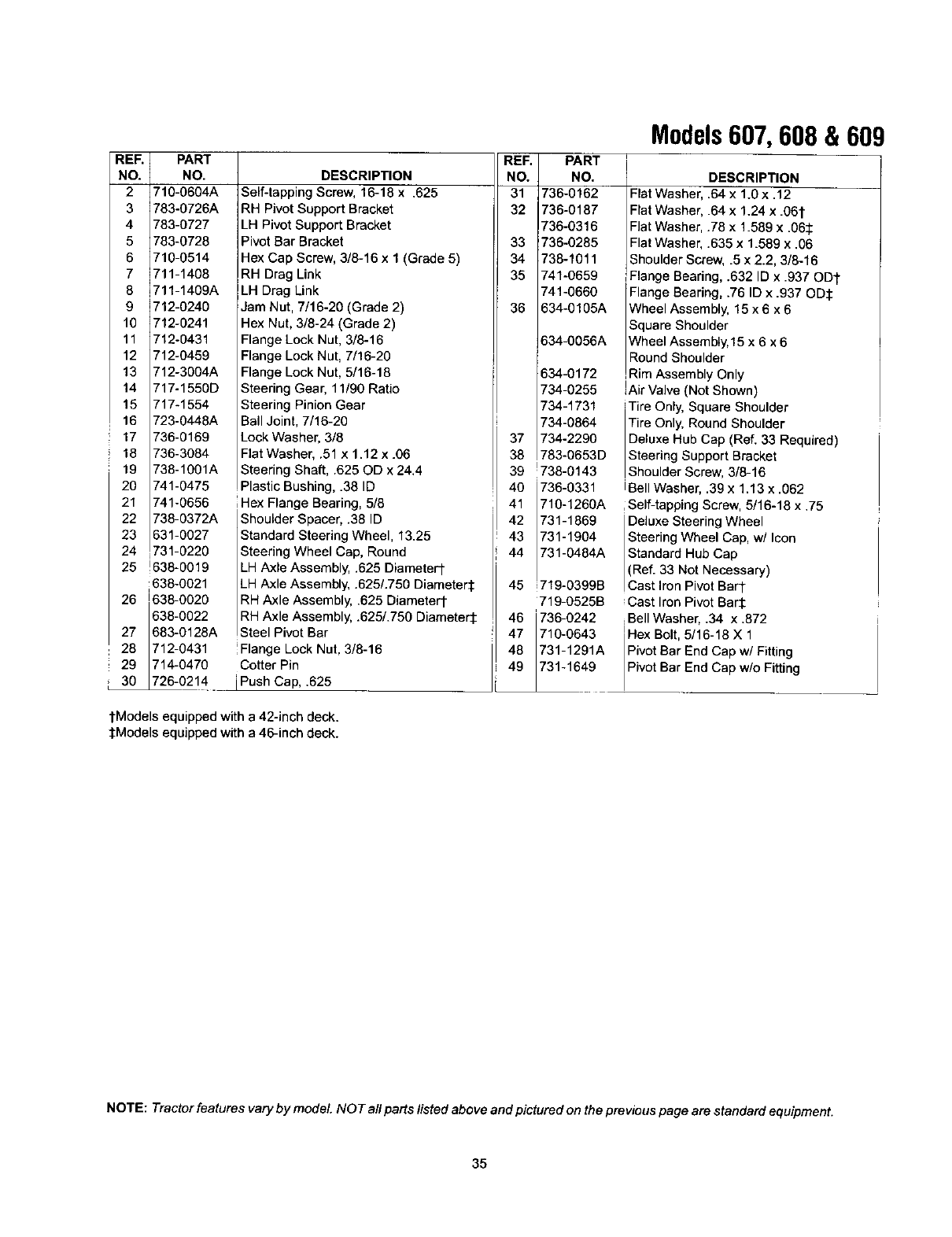
REF.
NO.
2
3
4
5
6
7
8
9
10
11
12
PART
NO.
710-0604A
783-0726A
783-0727
783-0728
710-0514
711-1408
711-1409A
!712-0240
;712-0241
712-0431
712-0459
13 712-3004A
14 717-1550D
15 717-1554
16 723-0448A
17 736-0169
18 736-3084
19 738-1001A
20 741-0475
21 741-0656
22 738-0372A
23 631-0027
24 731-0220
25 !638-0019
638-0021
i
26 638-0020
638-0022
27 1683-0128A
28 1712-0431
29 1714-0470
_0214
DESCRIPTION
Self-tapping Screw, 16-18 x .625
RH Pivot Support Bracket
LH Pivot Support Bracket
Pivot Bar Bracket
Hex Cap Screw, 3/8-16 x 1 (Grade 5)
RH Drag Link
LH Drag Link
Jam Nut, 7/16-20 (Grade 2)
Hex Nut, 3/8-24 (Grade 2)
Flange Lock Nut, 3/8-16
Flange Lock Nut, 7/16-20
Flange Lock Nut, 5/16-18
Steering Gear, 11/90 Ratio
Steering Pinion Gear
Ball Joint, 7/16-20
LockWasher, 3/8
Flat Washer, .51 x 1.12 x .06
Steering Shaft, .625 OD x 24.4
PlasticBushing, .38 ID
iHex Flange Bearing, 5/8
Shoulder Spacer, .38 ID
Standard Steering Wheel, 13.25
Steering Wheel Cap, Round
LH Axle Assembly, .625 Diameter1-
LH Axle Assembly, .625/.750 Diameter'j:
RH Axle Assembly, .625 Diametert
RH Axle Assembly, .625/.750 Diameter:l:
Steel Pivot Bar
Flange Lock Nut, 3/8-16
Cotter Pin
iPush Cap, .625
tModels equipped with a 42-inch deck.
:[:Models equipped witha46-inch deck.
REF.
NO.
31
32
33
34
35
36
PART
NO.
736-0162
736-0187
736-0316
736-0285
738-1011
741-0659
741-0660
634-0105A
634-0056A
634-0172
734-0255
734-1731
734-0864
37 734-2290
38 783-0653D
39 _738-0143
40 736-0331
41 710-1260A
42 731-1869
43 731-1904
44 731-0484A
719 0399B45 i -
719-0525B
46 736-0242
47 710-0643
48 731-1291A
49 731-1649
Models607, 608 & 609
DESCRIPTION
Flat Washe_ .64 x 1.0 x .12
Flat Washer .64 x 1.24 x .061"
Flat Washez .78 x 1.589 x .06:1:
FlatWasher .635 x 1.589 x .06
Shoulder Screw, .5 x 2.2, 3/8-16
Flange Bearing,.632 ID x .937 ODt
Flange Searing, .76 ID x .937 OD:I:
Wheel Assembly, 15 x 6 x 6
Square Shoulder
Wheel Assembly,15 x 6 x 6
Round Shoulder
Rm Assembly Only
IAir Valve (Not Shown)
Tire Only, Square Shoulder
Tire Only, Round Shoulder
Deluxe Hub Cap (Ref. 33 Required)
Steering Support Bracket
Shoulder Screw, 3/8-16
IBell Washer, .39 x 1.13 x .062
,Self-tapping Screw, 5/16-18 x .75
Deluxe Steering Wheel
Steering Wheel Cap, w/Icon
Standard Hub Cap
(Ref. 33 Not Necessary)
Cast ron Pivot Barl-
Cast Iron Pivot Bar'l:
iBell Washer, .34 x .872
Hex Bolt,5/16-18 X 1
Pivot Bar End Cap w/Fitting
Pvct Bar End Cap w/o Fitting
NOTE: Tractor features vary by model. NOT all parts listed above and pictured on the previous page are standard equipment.
35
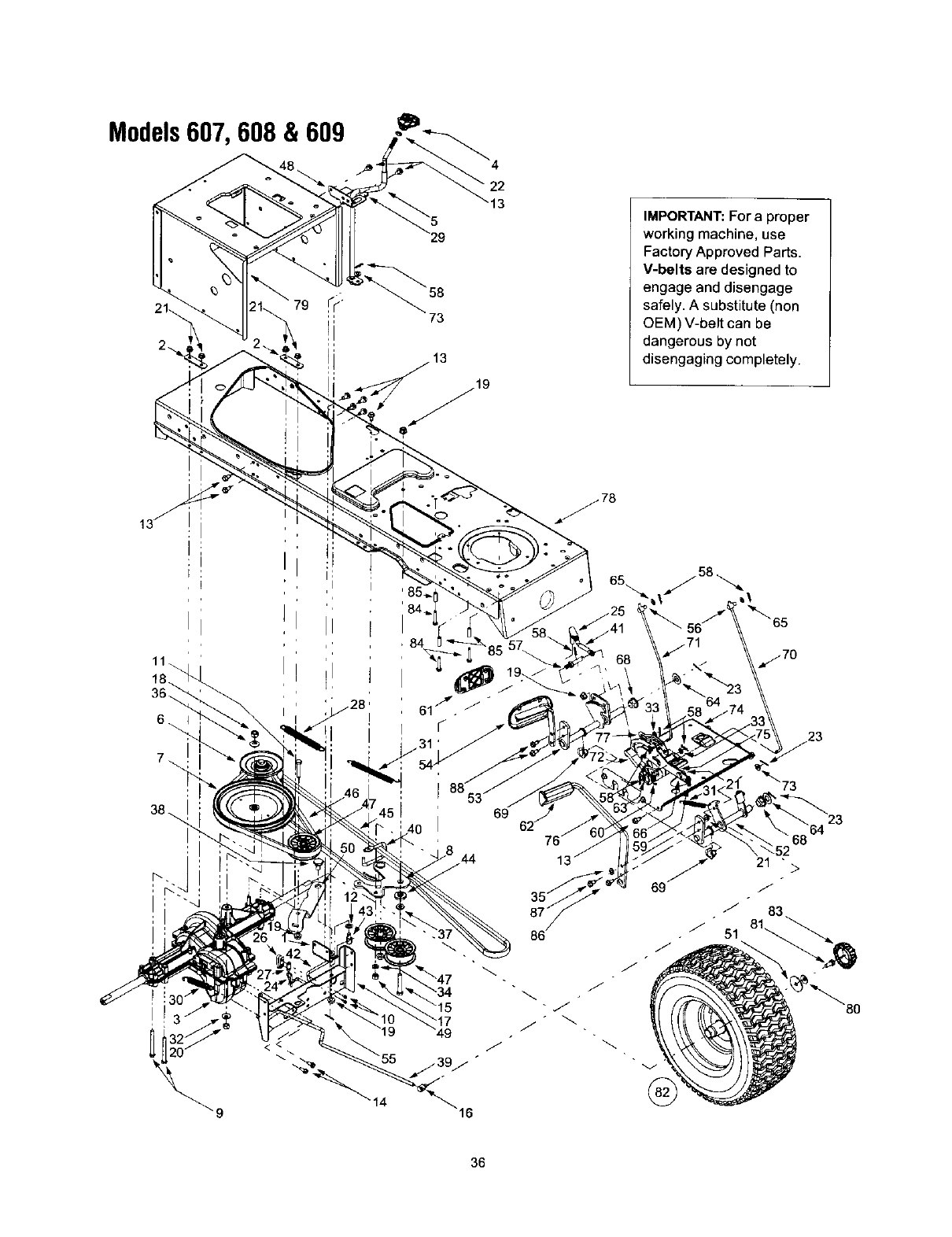
Models607, 608 & 609
29
73
22
IMPORTANT: For a proper
working machine, use
Factory Approved Parts.
V-belts are designed to
engage and disengage
safely. A substitute (non
OEM) V-belt can be
dangerous by not
disengaging completely.
.'T
57
9
69
J
-j
j
69
52
21 ">
/-
_" 83
51
64 23
36
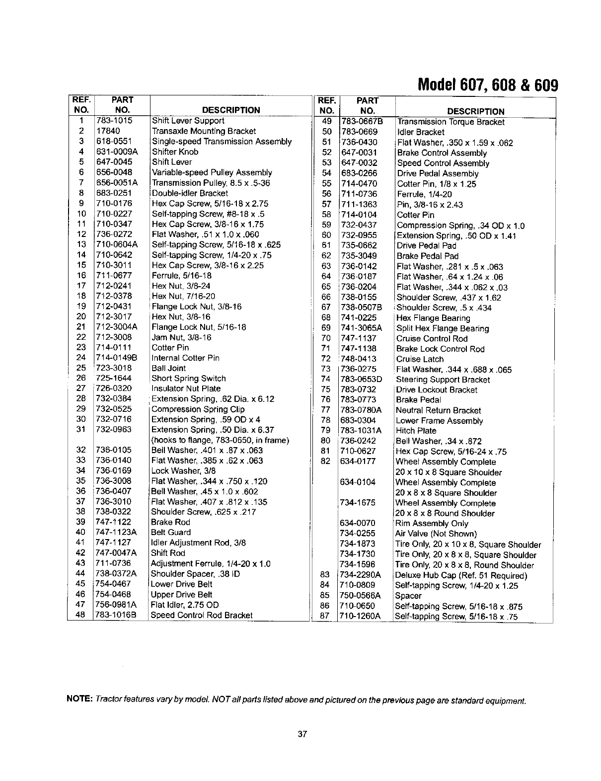
REF.
NO.
1
2
3
4
5
6
7
8
9
10
11
36
37
38
39
40
41
42
43
44
45
46
47
48
PART
NO.
783-1015
17840
618-0551
631-0009A
647-0045
656-0048
656-0051A
683-0251
710-0176
710-0227
710-0347
12 736-0272
13 710-0604A
14 710-0642
15 710-3011
16 711-0677
17 712-0241
18 712-0378
19 712-0431
20 712-3017
21 712-3004A
22 712-3006
23 714-0111
24 714-0149B
25 _723-3016
26 725-1644
27 i726-0320
28 732-0384
29 732-0525
30 732-0716
31 732-0963
32 736-0105
33 736-0140
34 736-0169
35 736-3008
736-0407
736-3010
738-0322
747-1122
747-1123A
747-1127
747-0047A
711-0736
738-0372A
754-0467
754-0468
756-0981A
783-1016B
DESCRIPTION
Shift Lever Support
TransaxleMounting Bracket
Single-speedTransmissionAssembly
Shifter Knob
ShiftLever
Variable-speed Pulley Assembly
TransmissionPulley, 8.5 x .5-36
Double-idler Bracket
Hex Cap Screw, 5/16-16 x 2.75
Self-tappingScrew, #8-18 x .5
Hex Cap Screw, 3/8-16 x 1.75
Flat Washer, .51 x 1.0 x .060
Self-tapping Screw, 5/16-18 x .625
Self-tapping Screw, 1/4-20 x .75
Hex Cap Screw, 3/8-16 x 2.25
Ferrule, 5/16-18
Hex Nut, 3/8-24
iHex Nut, 7/16-20
IFlange Lock Nut, 3/8-16
Hex Nut, 3/8-16
Flange Lock Nut, 5/16-18
Jam Nut, 3/8-16
Cotter Pin
Internal Cotter Pin
IBall Joint
,Short Spring Switch
Insulator Nut Plate
i Extension Spring, .62 Dia. x 6.12
Compression Spring Clip
Extension Spring, .59 OD x 4
Extension Spring, .50 Dia. x 6.37
(hooks to flange, 783-0650, in frame)
Bell Washer, .401 x .87 x .063
Flat Washer, .385 x .62 x .063
Lock Washer, 3/8
Flat Washer, .344 x .750 x .120
Bell Washer, .45 x 1.0 x .602
Flat Washer, .407 x .812 x. 135
Shoulder Screw, .625 x .217
Brake Rod
Belt Guard
Idler Adjustment Rod, 3/8
Shift Rod
Adjustment Ferrule, 1/4-20 x 1.0
Shoulder Spacer, .38 ID
Lower Drive Belt
Upper Drive Belt
Flat Idler, 2.75 OD
Speed Control Rod Bracket
REF.
NO.
49
50
51
52
53
54
55
56
57
58
59
60
61
62
63
64
65
66
67
68
69
7O
71
72
73
74
75
76
77
78
79
80
81
82
83
84
85
86
87
PART
NO.
783-0667B
783-0669
736-0430
647-0031
647-0032
683-6266
714-6470
711-0736
711-1363
714-0104
732-0437
732-0955
735-0662
736-3049
736-0142
736-0187
736-6264
738-0155
738-0507B
741-0225
741-3066A
747-1137
747-1138
1748-0413
736-0275
783-0653D
783-0732
783-0773
783-0780A
683-0304
783-1031A
736-0242
710-0627
634-0177
634-0104
734-1675
634-0070
734-0255
734-1873
734-1730
734-1596
734-2290A
710-0809
750-0566A
710-0650
710-1260A
Model607, 608 &609
DESCRIPTION
TransmissionTorqueBracket
Idler Bracket
Flat Washer, .350 x 1.59 x .062
Brake Control Assembly
Speed Control Assembly
Drive Pedal Assembly
Cotter Pin, 1/8 x 1.25
Ferrule, 1/4-20
Pin, 3/8-16 x 2.43
Cotter Pin
Compression Spring, .34 OD x 1.0
Extension Spring, .50 OD x 1.41
Drive Pedal Pad
Brake Pedal Pad
Flat Washer, .281 x .5 x .063
Flat Washer, .64 x 1.24 x .06
Flat Washer, .344 x .062 x .03
Shoulder Screw, .437 x 1.62
Shoulder Screw, .5 x .434
Hex Flange Bearing
Split Hex Flange Bearing
Cruise Control Rod
Brake Lock Control Rod
Cruise Latch
!Flat Washer, .344 x .688 x.065
Steering Support Bracket
Drive Lockout Bracket
Brake Pedal
Neutral Return Bracket
Lower Frame Assembly
Hitch Plate
Bell Washer, .34 x .872
Hex Cap Screw, 5/16-24 x .75
Wheel Assembly Complete
20 x 10 x 8 Square Shoulder
Wheel Assembly Complete
20 x 8 x 8 Square Shoulder
Wheel Assembly Complete
20 x 8 x 8 Round Shoulder
Rim Assembly Only
Air Valve (Not Shown)
Tire Only, 20 x 10 x 8, Square Shoulder
Tire Only, 20 x 8 x 8, Square Shoulder
Tire Only, 20 x 8 x 8, Round Shoulder
Deluxe Hub Cap (Ref. 51 Required)
Self-tapping Screw, 1/4-20 x 1.25
Spacer
Self-tapping Screw, 5/16-18 x .875
Self-tapping Screw, 5/16-18 x .75
NOTE: Tractor features vary by model. NO Tall parts listed above and pictured on the previous page are standard equipment.
37
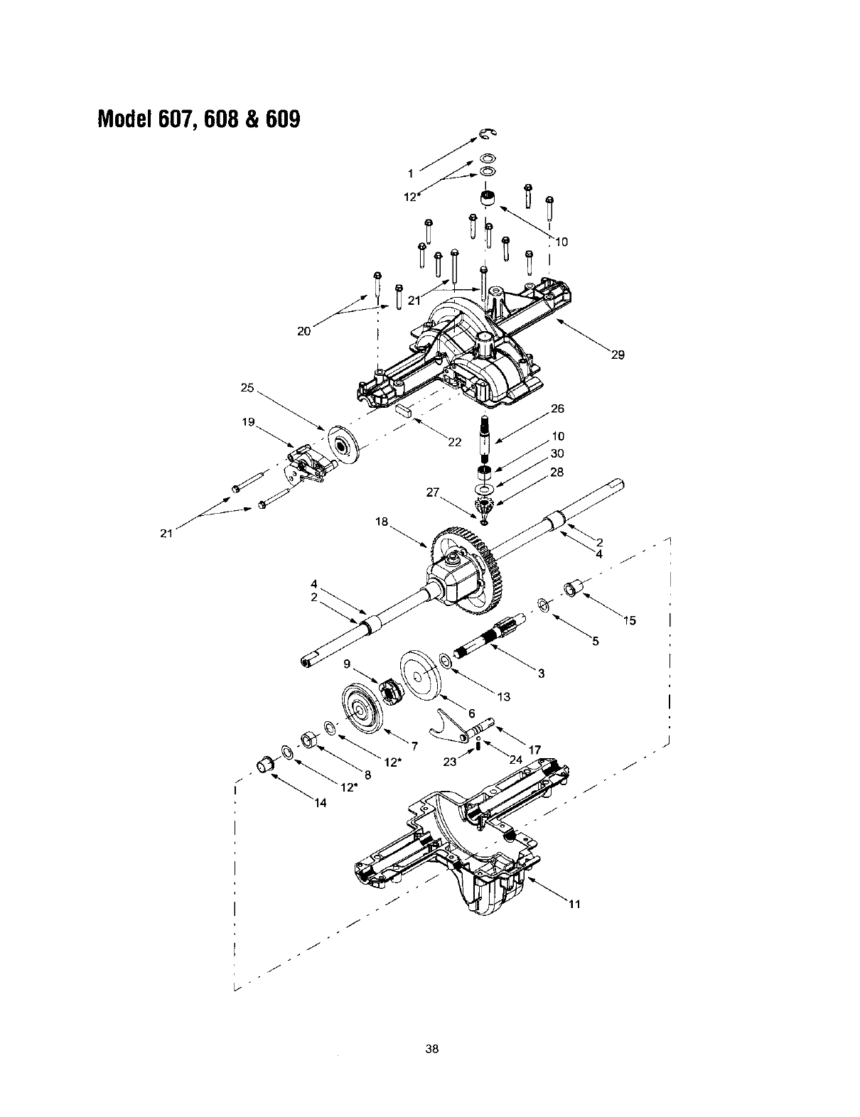
Model607, 608 & 609
2O
4
9
30
28
od
J
/
/
38

Model607,608 & 609
REF.
NO.
1
2
3
4
5
6
7
8
9
10
11
12a
12b
12c
13
14
15
16
17
18
19
20
21
22
23
24
25
26
27
28
29
PART
NO.
716-0231
721-0338
711-1431
741-0340
736-0495
717-1362
717-1383
750-1234
718-0228
741-0525
719-0394
736-0336
736-0337
736-9349
736-0519
741-0336
741-0337
_750-1238
611-0133
618-0424
661-0006
710-1325
710-1206
717-0678
1732-0863
1741-0862
_761-0202
_711-1430
716-0108
717-1464
719-0391A
736-0723
DESCRIPTION
E-ring, .75
Seal, .75 x 1.0 x .125
Drive Shaft
Sleeve Bearing, .75 x .1.0 x 1.0
Thrust Washer, 1.0 x .632 x .0
42-tooth Bevel Gear
42-tooth Bevel Gear
Spacer, .633 x 1.0 x .513
Clutch Collar
Needle Bearing, .625 x .875
Lower Housing
Flat Washel 5/8 x 1.0 x .030*
Flat WasheJ 5/8 x 1.0 x .040*
Flat WasheJ 5/8 x 1.0 x .020*
Flat Washer .70 x 1.125 x .031
Flange Bearing, 5/8 x 3/4 x 3/4
Flange Bearing, 5/8 x 3/4 x 15/16
Spacer, .635 x 1.0 x .27
Detent Shaft Assembly
Differential Assembly
Brake Assembly
Self-tapping Screw, 1/4-20 x 1.625
Self-tapping Screw, 1/4-20 x 2.375
Brake Pad
Compression Spring
Detent Ball
Brake Disc
Input Shaft
Retaining Ring, .437
14-tooth Bevel Pinion
Upper Housing
Thrust Washer, .635 x 1.25 x .042
*Use applicable flat washer (12a, 12b or 12c) in this application allowing proper end-play as instructed in MTD's Service Manual.
39
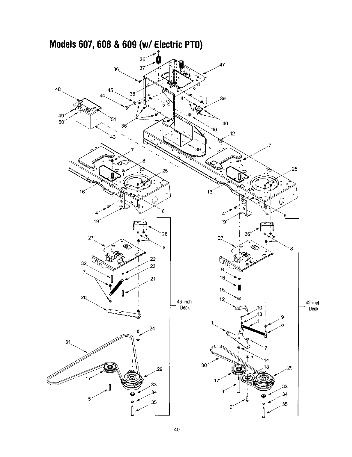
Models607, 608 & 609 (w/ ElectricPTO)
48
36
43
4O
_6
46-inch
-- Deck
1
42-inch
Deck
4O
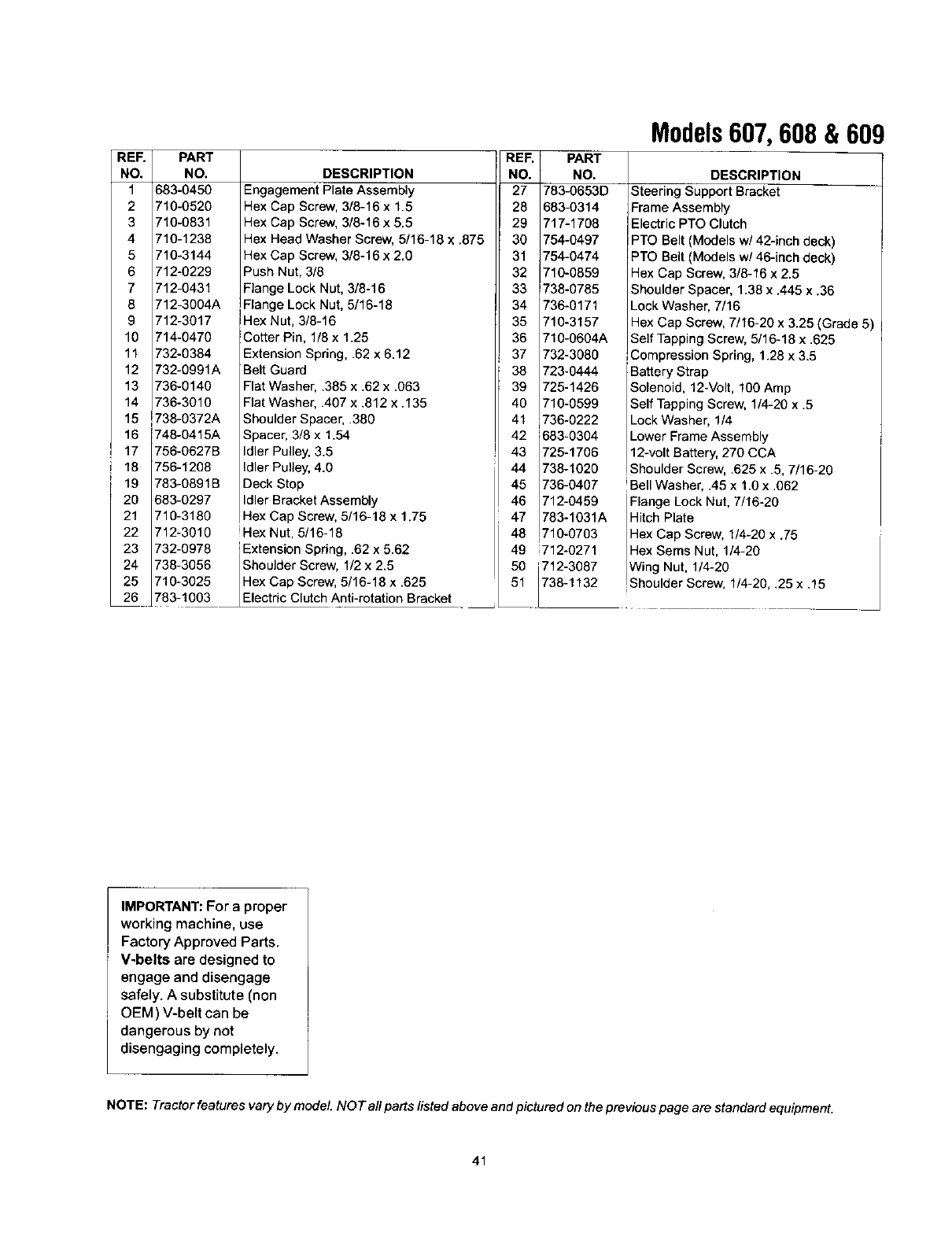
REE PART
NO. NO.
1 683-0450
2710-0520
3 710-0831
4710-1236
5 710-3144
6 712-0229
7 712-0431
8 712-3004A
9 712-3017
10 714-0470
11 732-0384
12 732-0991A
13 736-0140
14 736-3010
15 738-0372A
16 748-0415A
17 756-0627B
18 756-1208
19 783-0891B
20 683-0297
21 710-3180
22 712-3010
23 732-6978
24 738-3056
25 710-3025
26 783-1003
DESCRIPTION
Engagement Plate Assembly
Hex Cap Screw, 3/8-16 x 1.5
Hex Cap Screw, 3/8-16 x 5.5
Hex Head Washer Screw, 5/16-18 x .875
Hex Cap Screw, 3/8-16 x 2.0
Push Nut, 3/8
Flange Lock Nut, 3/8-16
Flange Lock Nut, 5/15-18
Hex Nut, 3/8-16
Cotter Pin, 1/8 x 1.25
Extension Spring, .62 x 6.12
Belt Guard
Flat Washer, .385 x .62 x .063
Flat Washer, .407 x .812 x .135
Shoulder Spacer, .380
Spacer, 3/8 x 1.54
Idler Pulley,3.5
Idler Pulley, 4.0
Deck Stop
Idler BracketAssembly
Hex Cap Screw, 5/16-18 x 1.75
Hex Nut, 5/16-18
'Extension Spring, .62 x 5.62
Shoulder Screw, 1/2 x 2.5
Hex Cap Screw, 5/16-18 x .625
Eectric Clutch Anti-rotation Bracket
REF
NO.
27
28
29
30
31
32
33
34
35
36
37
38
39
40
41
42
43
44
45
46
47
48
PART
NO.
783-0653D
583-0314
717-1708
754-0497
754-0474
710-0859
738-0785
736-0171
710-3157
710-0604A
732-3080
723-0444
725-1426
710-0599
736-0222
683-0304
725-1706
738-1020
736-0407
712-0459
783-1031A
710-0703
Models607, 608 & 609
DESCRIPTION
Steering Support Bracket
FrameAssembly
ElectricPTO Clutch
PTO Belt (Models w/42-inch deck)
PTO Belt (Models w/46-inch deck)
Hex Cap Screw, 3/8-16 x 2.5
Shoulder Spacer, 1.38 x .445 x.36
Lock Washer, 7/16
Hex Cap Screw, 7/16-20 x 3.25 (Grade 5)
Self TappingScrew, 5/16-18 x.625
Compression Spring, 1.28 x 3.5
Battery Strap
Solenoid, 12-Volt, 100 Amp
Self TappingScrew, 1/4-20 x .5
Lock Washer, 1/4
Lower Frame Assembly
12-voltBattery,270 CCA
Shoulder Screw, .625 x .5, 7/16-20
!Bell Washer, .45 x 1.0 x .062
Flange Lock Nut, 7/16-20
HitchPlate
Hex Cap Screw, 1/4-20 x.75
Hex Sems Nut, 1/4-20
IWin Nut, 1/4-20
_Shoulder Screw, 1/4-20, .25 x .15
49 i712-0271
50 1712-3087
51 _./738-1132
IMPORTANT: For aproper
working machine, use
Factory Approved Parts.
V-belts are designed to
engage and disengage
safely. A substitute (non
OEM) V-belt can be
dangerous by not
disengaging completely.
NOTE: Tractor features vary by model NOT aflparts/isted above and pictured on theprevious page are standard equipment.
41
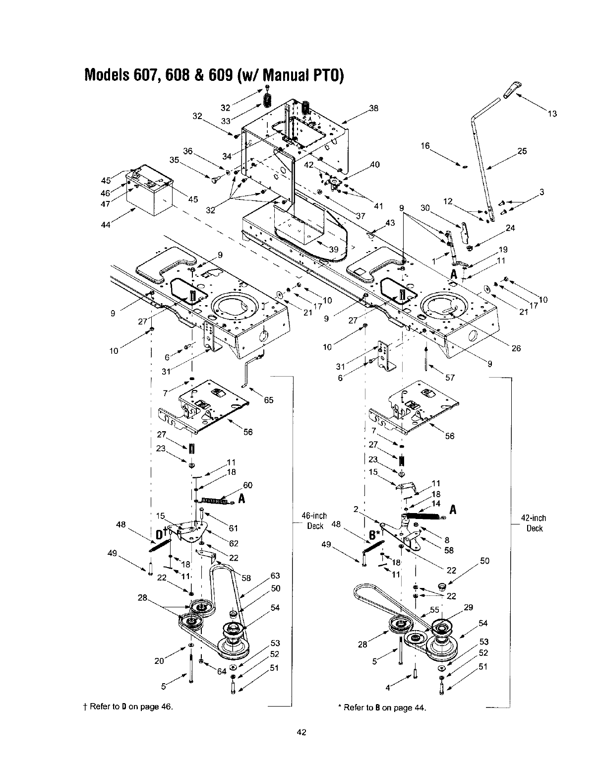
Models607, 608 & 609 (w/Manual PTO)
32
16
13
9 30
927
15
48
5J
¢ Refer to Don page 46.
56
54
46-inch
-- Deck
A
48
* Refer to Bon page 44.
26
42-inch
Deck
42
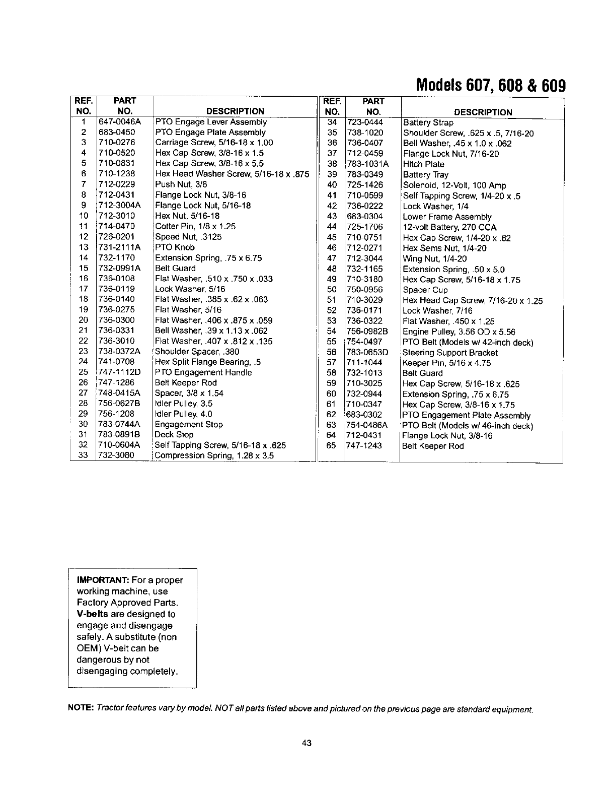
REF.
NO.
1
2
3
4
5
6
7
8
9
10
11
12
PART
NO.
647-0046A
683-0450
710-0276
710-0520
710-0831
710-1238
712-0229
712-0431
712-3004A
712-3010
714-0470
726-0201
13 731-2111A
14 732-1170
15 732-0991A
16 736-0108
17 736-0119
18 736-0140
19 736-0275
20 736-0300
21 736-0331
22 736-3010
23 738-0372A
24 741-0708
25 747-1112D
26 1747-1286
27 1748-0415A
28 756-0627B
I 29 756-1208
30 783-0744A
31 783-0891B
32 710-0604A
33 732-3080
DESCRIPTION
PTO Engage Lever Assembly
PTO Engage Plate Assembly
Carriage Screw, 5/16-18 x 1.00
Hex Cap Screw, 3/6-16 x 1.5
Hex Cap Screw, 3/8-16 x 5.5
Hex Head Washer Screw, 5/16-18 x .875
Push Nut, 3/8
Flange Lock Nut, 3/8-16
Flange Lock Nut, 5/16-18
Hex Nut, 5/16-18
Cotter Pin, 1/8 x 1.25
Speed Nut, .3125
PTO Knob
ExtensionSpring, .75 x 6.75
Belt Guard
Flat Washer .510 x .750 x .033
LockWashep 5/16
Flat Washer .385 x .62 x .063
Flat Washer 5/16
Flat Washer .406 x .875 x .059
Bell Washer .39 x 1.13 x .062
Flat Washer .407 x .812 x .135
!Shoulder S _acer,.380
Hex Split Flange Bearing, .5
PTO Engagement Handle
Belt Keeper Rod
Spacer, 3/8 x 1.54
IdlerPulley, 3.5
Idler Pulley, 4.0
Engagement Stop
Deck Stop
!Self Tapping Screw, 5/16-18 x .625
[Compression Spring, 1.28 x 3.5
REF PART
NO. NO.
34 723-0444
35 i738-1020
36 736-0407
37 712-0459
38 783-1031A
39 78:3-0349
40 726-1426
41 710-0599
42 736-0222
43 683-0364
44 726-1706
45 710-0751
46 712-0271
47 712-3044
48 732-1165
49 710-3180
50 75O-O956
51 710-3029
52 736-0171
53 736-0322
54 756-0982B
55 754-0497
56 783-0653D
57 711-1044
58 732-1013
59 710-3025
60 732-0944
61 710-0347
62 !683-0302
63 1754-0486A
64 712-0431
65 747-1243
Models607, 608 & 609
DESCRIPTION
Battery Strap
Shoulder Screw, .625 x .5, 7/16-20
Bell Washer, .45 x 1.0 x .062
Flange Lock Nut, 7/16-26
Hitch Plate
Battery Tray
Solenoid, 12-Volt, 100 Amp
Self Tapping Screw, 1/4-20 x .5
Lock Washer, 1/4
Lower Frame Assembly
12-volt Battery, 270 CCA
Hex Cap Screw, 1/4-20 x .62
Hex Seres Nut, 1/4-20
Wing Nut, 1/4-20
Extension Spring, .50 x 5.0
Hex Cap Screw, 5/16-18 x 1.75
Spacer Cup
Hex Head Cap Screw, 7/16-20 x 1.25
Lock Washer, 7/16
Flat Washer, .450 x 1.25
Engine Pulley, 3.56 OD x 5.56
PTO Belt (Models w/42-inch deck)
Steering Support Bracket
Keeper Pin, 5/16 x 4.75
Belt Guard
Hex Cap Screw, 5/16-18 x .625
Extension Spring, .75 x 6.75
Hex Cap Screw, 3/8-16 x 1.75
PTO Engagement Plate Assembly
'PTO Belt (Models w/46-inch deck)
Flange Lock Nat, 3/8-16
Be t Keeper Rod
IMPORTANT: For a proper
working machine, use
Factory Approved Parts.
V-belts are designed to
engage and disengage
safely. A substitute (non
OEM) V-belt can be
dangerous by not
disengaging completely.
NOTE: Tractor features vary by model NOT all parts listed above and pictured on the previous page are standard equipment.
43
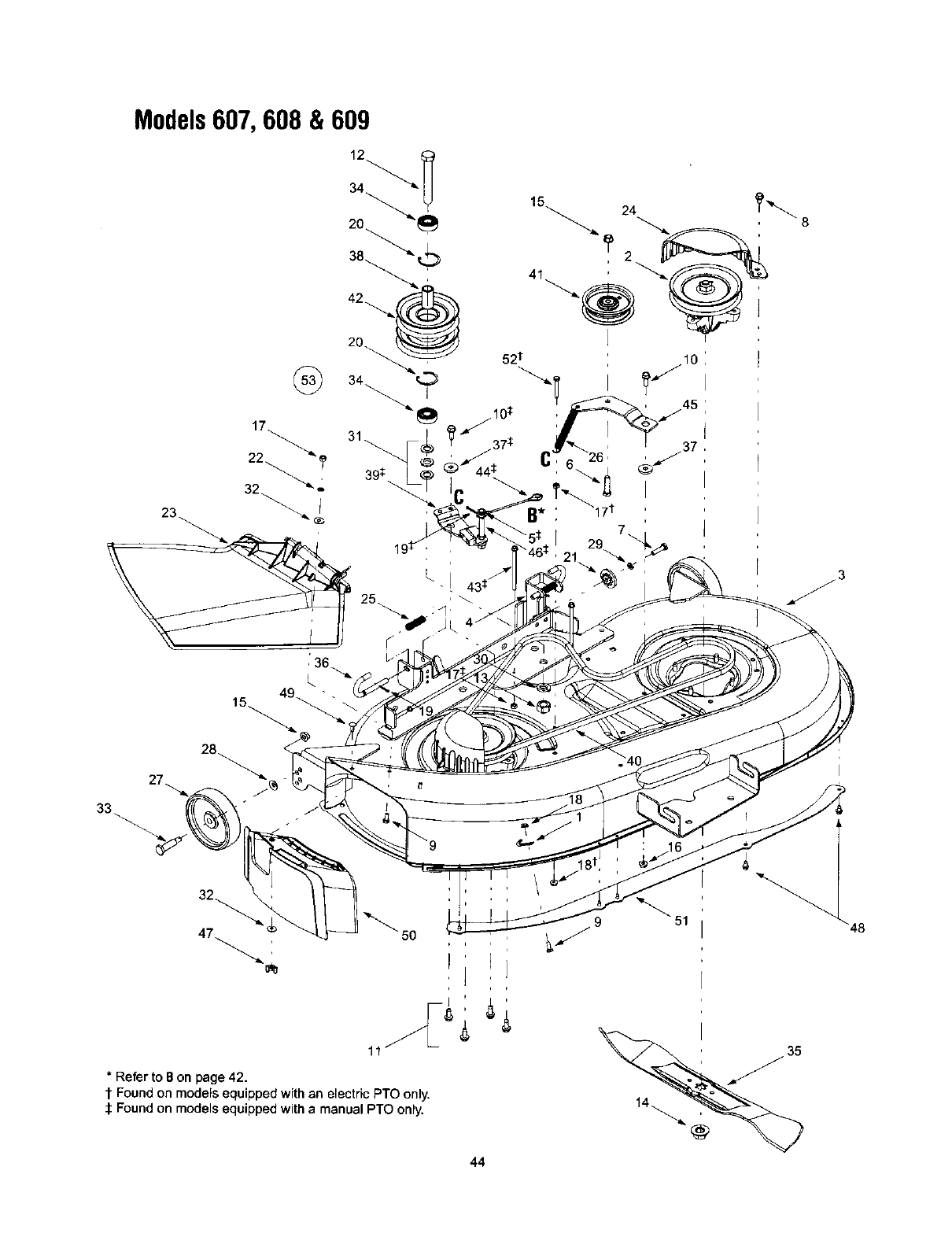
Models607, 608 & 609
35
*Refer to Bon page 42.
t Found on models equipped with an electric PTO only.
:1:Found on models equipped with amanual PTO only.
44
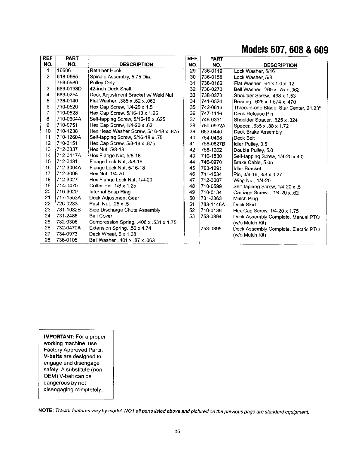
REF.
NO.
1
2
PART
NO.
16606
518-0565
1756-0980
3 1683-0198D
4683-0254
5 736-0140
6 710-0520
7 710-0528
8 710-0604A
9 710-0751
10 710-1238
11 710-1260A
12 710-3151
13 712-0337
14 712-0417A
15 712-0431
16 712-3004A
17 712-3006
18 712-3027
19 714-0470
20 716-3020
21 717-1553A
22 !726-0233
23 731-1032B
24 731-2486
25 732-0306
26 732-0470A
27 734-O973
28 736-0105
DESCRIPTION
Retainer Hook
Spindle Assembly, 5.75 Dia.
Pulley Only
42-inch Deck Shell
Deck Adjustment Bracket w/Weld Nut
Flat Washer, .385 x .62 x .063
Hex Cap Screw, 1/4-20 x 1.5
Hex Cap Screw, 5/16-18 x 1.25
Self-tapping Screw, 5/16-18 x .625
Hex Cap Screw, 1/4-20 x .62
Hex Head Washer Screw, 5/16-18 x .875
Self-tapping Screw, 5/16-18 x .75
Hex Cap Screw, 5/8-18 x .875
Hex Net, 5/8-18
Hex Flange Nut, 5/8-18
Flange Lock Nut, 3/8-16
Flange Lock Nut, 5/16-18
Hex Nut, 1/4-20
Hex Flange Lock Nut, 1/4-20
Cotter Pin, 1/8 x 1.25
nterna Snap Ring
Deck Adjustment Gear
Push Nut..25 x .5
Side Discharge Chute Assembly
Belt Cover
Compression Spring, .406 x .531 x 1.75
Extension Spring, .50 x 4.74
Deck Wheel, 5 x 1.38
Bell Washer, .401 x .87 x .063
-RER PART
NO. NO.
29 736-0119
30 736-0158
31 736-0162
32 736-0270
33 736-0373
34 741-0524
35 742-0616
36 747-1116
37 748-0331
38 750-0932A
39 683-0440
40 754-0498
41 756-0627B
42 756-1202
43 710-1830
44 746-0970
45 783-1291
46 711-1534
47 712-3087
48 710-0599
49 1710-0134
50 ,731-2363
51 783-1146A
52 710-0136
53 753-0894
753-0896
Models607, 608 & 609
DESCRIPTION
LockWasher, 5/16
Lock Washer, 5/8
Flat Washer, .64 x1.0 x .12
Sell Washer, .265 x .75 x .062
ShoulderScrew, .498 x 1.53
Searing, .625 x 1.574 x .470
Three-in-one Blade, Star Center, 21.23"
Deck Release Pin
Shoulder Spacer, .625 x .324
Spacer, .635 x .88 x 1.72
Deck BrakeAssembly
Deck Belt
Idler Pulley,3.5
Double Pulley,5.0
Self-tapping Screw, 1/4-20 x 4.0
Brake Cable, 5.05
IdlerBracket
Pin, 3/6-16, 3/6 x 3.27
Wing Nut, 1/4-20
Self-tapping Screw, 1/4-20 x .5
Carriage Screw,, 1/4-20 x .62
Mulch Plug
Deck Skirt
iHex Cap Screw, 1/4-20 x 1.75
Deck Assembly Complete, Manual PTO
(w/o Mulch Kit)
Deck Assembly Complete, Electric PTO
(w/o Mulch Kit)
IMPORTANT: For a proper
working machine, use
Factory Approved Parts.
V-belts are designed to
engage and disengage
safely. Asubstitute (non
OEM) V-belt can be
dangerous by not
disengaging completely.
NOTE: Tractor features vary by model NOT a/I parts/isted above and pictured on the previous page are standard equipment.
45
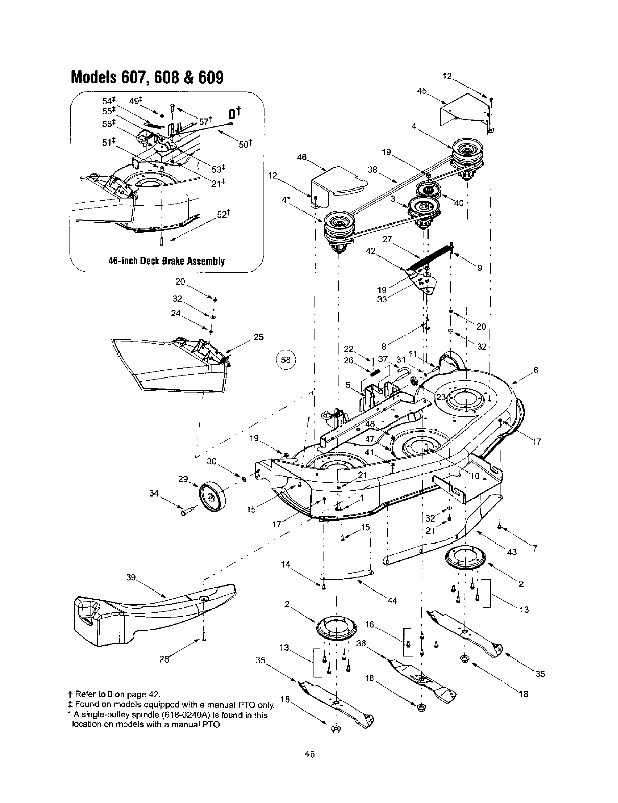
Models607, 608 & 609
46-inchDeckBrakeAssembly J
4
19
I
27
J" 14 , , i
t Refer to g on page 42. 18 _'_. _'_ _18
:I:Found on models equipped with a manual PTO only. _... "'_ ._ _
* A single-pulley spindle (618-0240A) is found in this _ _'_
location on models with a manual PTO. "_
46
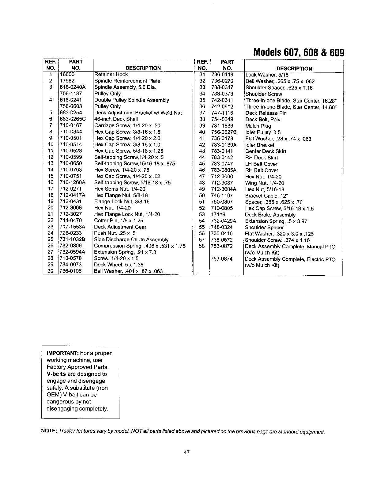
REF.
NO,
1
2
3
4
5
6
7
8
9
10
11
29
PART
NO.
16606
17982
618-0240A
756-1187
618-0241
756-0603
683-0254
683-0265C
710-0167
710-0344
710-0501
710-0514
710-0528
12 710-0599
13 710-0650
14 710-0703
15 710-0751
16 710-1260A
17 712-0271
18 712-0417A
19 712-0431
20 712-3006
21 712-3027
22 714-0470
23 717-1553A
24 726-0233
25 731-1032B
26 1732-0306
27 ;732-0594A
710-0578
734-0973
736-0105
DESCRIPTION
Retainer Hook
Spindle ReinforcementPlate
SpindleAssembly, 5.0 Dia.
Pulley Only
Double Pulley Spindle Assembly
Pulley Only
Deck Adjustment Bracketw/Weld Nut
46-inch Deck Shell
Carriage Screw, 1/4-20 x .50
Hex Cap Screw, 3/8-16 x 1.5
Hex Cap Screw, 1/4-20 x 2.0
Hex Cap Screw,3/8-16 x 1.0
Hex Cap Screw,5/8-18 x 1.25
Self-tapping Screw,1/4-20 x .5
Self-tapping Screw,15/16-18 x .875
Hex Screw, 1/4-20 x .75
Hex Cap Screw, 1/4-20 x .62
Self-tapping Screw, 5/16-18 x .75
Hex Sems Nut, 1/4-20
Hex Flange Nut, 5/8-18
Flange Lock Nut, 3/8-16
Hex Nut, 1/4-20
Hex Flange Lock Nut, 1/4-20
Cotter Pin, 1/8 x 1.25
Deck Adjustment Gear
Push Nut..25 x .5
Side Discharge Chute Assembly
Compression Spring, .406 x .531 x 1.75
Extension Spring, .91 x 7.3
Screw, 1/4-20 x 1.5
Deck Wheel, 5 x 1.38
Be Washer, .401 x .87 x .063
iREF. PART
NO. NO.
31 736-0119
32 736-0270
33 738-0347
34 738-0373
35 742-0611
36 742-0612
37 747-1116
38 754-6349
39 731-1636
40 756-0627B
41 736-0173
42 783-0139A
43 783-0141
44 783-0142
45 783-0747
46 783-0805A
47 712-3006
48 712-3087
49 712-3004A
50 746-1107
51 750-0807
52 710-0805
53 17116
54 732-0429A
55 748-0324
56 736-0416
57 738-0572
58 753-0872
753-0874
Models607, 608 & 609
DESCRIPTION
Lock Washer, 5/16
Bell Washer, .265 x .75 x .062
Shoulder Spacer, .625 x 1.16
Shoulder Screw
Three-in-one Blade, Star Center, 16.28"
Three-in-one Blade, Star Center, 14.88"
Deck Release Pin
Deck Belt, Poly
Mulch Plug
Idler Pulley,3.5
Flat Washer, .28 x .74 x .063
Idler Bracket
Center Deck Skirt
RH Deck Skirt
LH Belt Cover
RH Belt Cover
Hex Nut, 1/4-20
Wing Nut, 1/4-20
iHex Nut, 5/16-18
Bracket Cable, 12"
Spacer, .385 x .625 x .70
Hex Cap Screw, 5/16-18 x 1.5
Deck Brake Assembly
Extension Spring, .5 x 3.97
Shoulder Spacer
,Flat Washer 320 x 3 0 x .125
Shoulder Screw, .374 x 1.16
Deck Assembly Complete, Manual PTO
(w/o Mulch Kit)
Deck Assembly Complete, Electric PTO
w/o Mulch Kit)
IMPORTANT: For a proper
working machine, use
Factory Approved Parts.
V-belts are designed to
engage and disengage
safely. Asubstitute (non
OEM) V-belt can be
dangerous by not
disengaging completely.
NOTE: Tractor features vary by model. NOT all parts fisted above and pictured on the previous page are standard equipment.
47

MANUFACTURER'S
LIMITED WARRANTY
The limited warranty set forth below is given by MTD
PRODUCTS INC ("MTD") with respect to new merchandise
purchased and used in the United States, its possessions
and territories.
MTD warrants this product against defects in material and
workmanship for a period of two (2) years commencing on
the date of original purchase and will, at its option, repair or
replace, free of charge, any part found to be defective in
material or workmanship. This limited warranty shall only
apply if this product has been operated and maintained in
accordance with the Operator's Manual furnished with the
product, and has not been subject to misuse, abuse, com-
mercial use, neglect, accident, improper maintenance,
alteration, vandalism, theft, fire, water or damage because
of other peril or natural disaster. Damage resulting from the
installation or use of any accessory or attachment not
approved by MTD Products Inc. for use with the product(s)
covered by this manual will void your warranty as to any
resulting damages.
Normal wear parts or components thereof are subject to
separate terms as follows: All normal wear par[ or compo-
nent failures will be covered on the product for a period of
90 days regardless of cause. After 90 days, but within the
two year period, normal wear part failures will be covered
ONLY IF caused by defects in material or workmanship of
OTHER component parts. Normal wear parts and compo-
nents include, but are not limited to, belts, blades, blade
adapters, grass bags, rider deck wheels, seats, snow
thrower skid shoes, shave plates and tires. Batteries are
covered by a 90-day limited replacement warranty.
HOW TO OBTAIN SERVICE: Warranty service is available,
WITH PROOF OF PURCHASE THROUGH YOUR LOCAL
AUTHORIZED SERVICE DEALER. To locate the dealer in
your area, please check for a listing in the Yellow Pages or
contact the Customer Service Department of MTD PROD-
UCTS INC by calling 1-800-800-7310 or writingto RO. Box
368022, Cleveland, Ohio 44136-9722.
This limited warranty does not provide coverage in the
following cases:
a.The engine or component parts thereof. These items
carry aseparate manufacturer'swarranty. Please refer
to the applicable manufacturer's warranty on these
items.
b. Log splitter pumps, valves and cylinders have a sepa-
rate one year warranty.
c. Routine maintenance items such as lubricants,filters,
blade sharpening and tune-ups, or adjustments such
as brake adjustments, clutch adjustments or deck
adjustments; and normal deterioration of the exterior
finish due to use or exposure.
d. MTD does not extend any warranty for producLs sold
or exported outside of the United States of America,
its possessions and territories, except those SOld
through MTD's authorized channels of export distribu-
tion.
No implied warranty, including any implied warranty of
merchantability or fitness for a particular purpose,
applies after the applicable period of express written
warranty above as to the parts as identified. No other
express warranty or guaranty, whether written or oral,
except as mentioned above, given by any person or
entity, including a dealer or retailer, with respect to any
product shall bind MTD. During the period of the War-
ranty, the exclusive remedy is repair or replacement of
the product as set forth above. (Some states do not
allow limitations on how long an implied warranty lasts, so
the above limitation may not apply to you.)
The provisions as set forth in this Warranty provide the
sole and exclusive remedy arising from the sales. MTD
shall not be liable for incidental or consequential loss
or damages including, without limitation, expenses
incurred for substitute or replacement lawn care ser-
vices, for transportation or for related expenses, or for
rental expenses to temporarily replace a warranted
product. (Some states do not allow the exclusion or limita-
tion of incidental or consequential damages, so the above
exclusion or limitation may not apply to you,)
In no event shall recovery of any kind be greater than the
amount of the purchase price of the product sold. Alteration
of the safety features of the product shall void this War-
rarity. You assume the risk and liability for loss, damage, or
injury to you and your property and/or to others and their
property arising out of the use or misuse or inability to use
the product.
This limited warranty shall not extend to anyone other than
the original purchaser, original lessee or the person for
whom it was purchased as a gift.
How State Law Relates to this Warranty: This limited
warranty gives you specific legal rights, and you may also
have other rightswhich vary from state to state.
