MTD 13AL78SS299 User Manual TRACTOR Manuals And Guides L1002356
MTD Lawn, Tractor Manual L1002356 MTD Lawn, Tractor Owner's Manual, MTD Lawn, Tractor installation guides
User Manual: MTD 13AL78SS299 13AL78SS299 MTD TRACTOR - Manuals and Guides View the owners manual for your MTD TRACTOR #13AL78SS299. Home:Lawn & Garden Parts:MTD Parts:MTD TRACTOR Manual
Open the PDF directly: View PDF ![]() .
.
Page Count: 92
perator's
I:RnFrSMRN°
LAWN TRACTOR
20 HP, Variation Speed
42" Deck
Model No. 247.28919
•Espanol, P. 59
This product has a low emission engine which operates differently
from previously built engines. Before you start the engine, read and
understand this Operator's Manual.
Before using this equipment,
read this manual and follow
all safety rules and operating
instructions.
For answers to your questions about
this product, Call:
1-800=659=5917
CraftsmanTractorHelp Line
7am = 7 pm CT, Mort. =Sun.
Sears Brands Management Corporation, Hoffman Estates, IL 60179 U.S.A.
Visit our website: www.craftsman.com FormNo.769-05815A
(February12,2010)
Off-Season Storage ........................................................ 27
Trou bleshooting .............................................................. 28
Labels ............................................................................. 29
Parts List ......................................................................... 30
Espafiol ............................................................................ 59
Service Numbers ............................................. Back Cover
CRAFTSMAN FULL WARRANTY
Whenoperatedand maintainedaccordingto allsuppliedinstructions,ifany non-expendablepartof thisridingequipmentfailsdueto a defectin
materialor workmanshipwithintwo yearsfromthedate orpurchase,call 1-800-659-5917to arrangefor free in-homerepair.
Theframeandfrontaxle will be repairedfreeof chargefor fiveyearsfromthe dateof purchaseif defectiveinmaterialor workmanship.
Allof the abovewarrantycoverageappliesfor only90 daysfromthe dateof purchaseifthis ridingequipmentiseverusedfor commercialor
rentalpurposes.
In allcases,if repairprovesimpossible,the ridingequipmentwill be replacedfree of chargewiththe sameoran equivalentmodel.
The batterywill be replacedfree of chargefor 90 daysfromthe dateof purchaseifdefectiveinmaterialorworkmanship(ourtestingprovesthat it
will notholda charge).
Thiswarranty coversONLYdefects in material andworkmanship. Sears will NOTpayfor:
o
o
o
o
Expendableitemsthatbecomewornduringnormaluse,includingbutnot limitedto blades,sparkplugs,aircleaners,belts,
andoilfilters.
Standardmaintenanceservicing,oilchanges,or tune-ups.
Tire replacementor repaircausedby puncturesfromoutsideobjects,suchas nails,thorns,stumps,or glass.
Tireor wheelreplacementor repairresultingfromnormalwear,accident,orimproperoperationor maintenance.
Repairsnecessarybecauseof operatorabuse,includingbutnot limitedto damagecausedby towingobjectsbeyondthe
capabilityof the ridingequipment,impactingobjectsthatbendtheframeorcrankshaft,or over-speedingthe engine.
Repairsnecessarybecauseof operatornegligence,includingbut not limitedto,electricalandmechanicaldamagecaused
by improperstorage,failureto use the propergradeandamountof engineoil, failureto keepthe deckclear of flammable
debris,orfailureto maintainthe ridingequipmentaccordingto the instructionscontainedinthe operator'smanual.
Engine(fuelsystem)cleaningor repairscausedbyfuel determinedto becontaminatedoroxidized(stale).In general,fuel
shouldbeusedwithin30daysof itspurchasedate.
Normaldeteriorationandwearof the exteriorfinishes,or productlabelreplacement.
Thiswarrantyappliesonly whilethisproductiswithinthe UnitedStates.
Thiswarrantygivesyou specificlegalrights,andyou mayalso haveotherrightswhichvaryfromstateto state.
Sears Brands ManagementCorporation, HoffmanEstates, IL 60179
GrossHP: 20
EngineOil: SAE30
Fuel: UnleadedGasoline
SparkPlug: Champion®RC12YC
Engine: Briggs& StrattonIntek®
Model Number:
Serial Number:
Dateof Purchase:
Recordthe modelnumber,serialnumber,
anddateof purchaseabove.
© KCDIRLLC 2
Thissymbolpointsout importantsafetyinstructionswhich,if not
followed,couldendangerthepersonalsafetyand/orpropertyof
yourselfandothers. Readandfollowall instructionsin thismanual
beforeattemptingto operatethismachine.Failureto complywith
theseinstructionsmayresultin personalinjury.Whenyou seethis
symbol,HEEDITSWARNING!
CALIFORNIA PROPOSITION 65
EngineExhaust,someof itsconstituents,andcertainvehicle
componentscontainoremitchemicalsknownto Stateof California
to causecancerandbirthdefectsorother reproductiveharm.
Batteryposts,terminals,and relatedaccessoriescontainleadand
leadcompounds,chemicalsknownto the Stateof Californiato
causecancerandreproductiveharm.Washhandsafterhandling.
Thismachinewasbuiltto beoperatedaccordingto the safeopera-
tion practicesinthis manual.As withanytypeof powerequipment,
carelessnessorerroron the partof the operatorcan resultin serious
injury.Thismachineis capableof amputatingfingers,hands,toes
andfeetandthrowingdebris.Failureto observethe followingsafety
instructionscouldresultin seriousinjuryor death.
Your Responsibility--Restrict the useof this powermachineto
personswho read,understandandfollowthewarningsand instruc-
tionsin thismanualandon the machine.
SAVE THESE INSTRUCTIONS!
GENERAL OPERATION
•Read,understand,andfollowall instructionson the machineand
in themanual(s)beforeattemptingto assembleandoperate.
Keepthis manualina safeplacefor futureand regularreference
andfor orderingreplacementparts.
• Befamiliarwithall controlsandtheir properoperation.Knowhow
to stopthe machineanddisengagethemquickly.
• Neverallowchildrenunder14yearsoldto operatethis machine.
Children14yearsoldandover shouldreadandunderstandthe
operationinstructionsandsafetyrulesinthismanualandshould
betrainedandsupervisedbya parent.
• Neverallowadultsto operatethis machinewithoutproper
instruction.
• Tohelpavoidbladecontactor a thrownobjectinjury,keep
bystanders,helpers,childrenandpetsat least75feetfromthe
machinewhile it is in operation.Stopmachineif anyoneenters
the area.
• Thoroughlyinspectthe areawherethe equipmentis to be used.
Removeallstones,sticks,wire,bones,toys,andotherforeign
objectswhichcouldbe pickedupandthrownby the blade(s).
Thrownobjectscan causeseriouspersonalinjury.
• Planyour mowingpatternto avoiddischargeof materialtoward
roads,sidewalks,bystandersandthe like.Also,avoiddischarg-
ingmaterialagainstawall orobstructionwhichmaycause
dischargedmaterialto ricochetbacktowardthe operator.
• Alwayswear safetyglassesor safetygogglesduringoperation
andwhile performingan adjustmentor repairto protectyoureyes.
Thrownobjectswhichricochetcancauseseriousinjuryto the
eyes.
• Wearsturdy,rough-soledworkshoesandclose-fittingslacksand
shirts.Loosefittingclothesandjewelrycanbe caughtin movable
parts.Neveroperatethismachineinbarefeetorsandals.
• Beawareof the mowerandattachmentdischargedirectionand
do not pointit at anyone.Donot operatethe mowerwithoutthe
dischargecoverorentiregrasscatcherin its properplace.
Donot put handsor feetnearrotatingpartsor underthe cutting
deck. Contactwiththe blade(s)can amputatehandsandfeet.
A missingor damageddischargecovercan causebladecontact
or thrownobjectinjuries.
• Stoptheblade(s)whencrossinggraveldrives,walks,or roads
andwhile notcuttinggrass.
• Watchfor trafficwhenoperatingnearorcrossingroadways.This
machineis not intendedfor useonany public roadway.
• Donot operatethe machinewhile underthe influenceof alcohol
or drugs.
• Mowonly indaylightorgoodartificiallight.
Nevercarrypassengers.
• Disengageblade(s)beforeshiftinginto reverse.Backup slowly.
Alwayslookdownandbehindbeforeandwhile backingto avoida
back-overaccident.
3
• Slowdownbeforeturning.Operatethe machinesmoothly.Avoid
erraticoperationandexcessivespeed.
Disengageblade(s),setparkingbrake,stopengineandwaituntil
the blade(s)cometo a completestopbeforeremovinggrass
catcher,emptyinggrass,uncloggingchute,removinganygrassor
debris,or makinganyadjustments.
Neverleavea runningmachineunattended.Alwaysturnoff
blade(s),setparkingbrake,stopengineandremovekeybefore
dismounting.
Useextracare whenloadingorunloadingthe machineintoa
trailerortruck.Thismachineshouldnot bedrivenupor down
ramp(s),becausethe machinecouldtip over,causingserious
personalinjury.The machinemustbe pushedmanuallyon
ramp(s)to loador unloadproperly.
Mufflerandenginebecomehotandcan causea burn.Do not
touch.
Checkoverheadclearancescarefullybeforedrivingunderlow
hangingtree branches,wires,dooropeningsetc.,wherethe
operatormaybestruckor pulledfromthe machine,whichcould
resultinseriousinjury.
Disengageallattachmentclutchesanddepressthe brakepedal
completelybeforeattemptingto start engine.
Yourmachineisdesignedto cutnormalresidentialgrassof a
heightnomorethan 10".Do not attemptto mowthroughunusually
tall,dry grass(e.g.,pasture)orpiles of dry leaves.Drygrassor
leavesmaycontactthe engineexhaustand/or builduponthe
mowerdeckpresentinga potentialfire hazard.
Useonlyaccessoriesandattachmentsapprovedfor this machine
by the machinemanufacturer.Read,understandandfollowall
instructionsprovidedwiththe approvedaccessoryor attachment.
Fora list of approvedaccessoriesandattachments,call 1-800-
659-5917.
Dataindicatesthatoperators,age60yearsandabove,are
involvedin a largepercentageof ridingmower-relatedinjuries.
Theseoperatorsshouldevaluatetheirabilityto operatethe riding
mowersafelyenoughto protectthemselvesandothersfrom
seriousinjury.
If situationsoccurwhicharenot coveredinthismanual,usecare
andgoodjudgment.Contact1-800-659-5917for informationand
assistance.
SLOPE OPERATION
Slopesarea majorfactorrelatedto lossof controlandtip-over
accidentswhichcan resultinsevereinjuryor death.Allslopesrequire
extracaution.Ifyoucannotbackupthe slopeor if youfeel uneasyon
it, do not mowit.
Foryoursafety,use the SlopeGuideincludedas partof this manual
to measureslopesbeforeoperatingthis machineona slopedor hilly
area. Ifthe slopeis greaterthan15degreesas shownonthe Slope
Guide,do notoperatethis machineonthatareaor seriousinjurycould
result.
Do:
oMowupanddown slopes,not across.Exerciseextremecaution
whenchangingdirectionon slopes.
• Watchfor holes,ruts,bumps,rocks,orother hiddenobjects.
Uneventerraincouldoverturnthe machine.Tallgrasscan hide
obstacles.
Useslowspeed.Choosea lowenoughspeedsettingso that
you will nothaveto stopor shiftwhileon the slope.Tiresmay
lose tractionon slopeseventhoughthe brakesarefunctioning
properly.Alwayskeepmachinein gearwhen goingdownslopes
to takeadvantageof enginebrakingaction.
• Followthe manufacturer'srecommendationsfor wheelweights
or counterweightsto improvestability.Forrecommendations,call
1-800-659-5917.
• Useextracarewithgrasscatchersor otherattachments.These
can changethe stabilityof the machine.
Keepallmovementonthe slopesslowandgradual.Do not make
suddenchangesinspeedor direction.Rapidengagementor
brakingcouldcausethe frontof the machineto lift andrapidlyflip
overbackwardswhichcouldcauseseriousinjury.
• Avoidstartingorstoppingona slope.Iftireslosetraction,disen-
gagethe blade(s)andproceedslowlystraightdownthe slope.
DoNot:
• Donot turnon slopesunlessnecessary;then,turnslowlyand
graduallydownhill,if possible.
• Donot mowneardrop-offs,ditchesor embankments.The mower
could suddenlyturnover if a wheelis overthe edgeof a cliff,
ditch,or if an edgecavesin.
• Donot try to stabilizethe machineby puttingyourfooton the
ground.
• Donot usea grasscatcheron steepslopes.
• Donot mowon wetgrass.Reducedtractioncouldcausesliding.
• Donot attemptto coastdownhill.Over-speedingmaycausethe
operatorto lose controlof the machineresultingin seriousinjury
or death.
• Donot towheavypull behindattachments(e.g.loadeddumpcart,
lawn roller,etc.)on slopesgreaterthan5 degrees.Whengoing
down hill,the extraweighttendsto pushthe tractorandmay
causeyou to loosecontrol(e.g.tractormayspeedup, brakingand
steeringabilityarereduced,attachmentmayjack-knifeandcause
tractorto overturn).
4
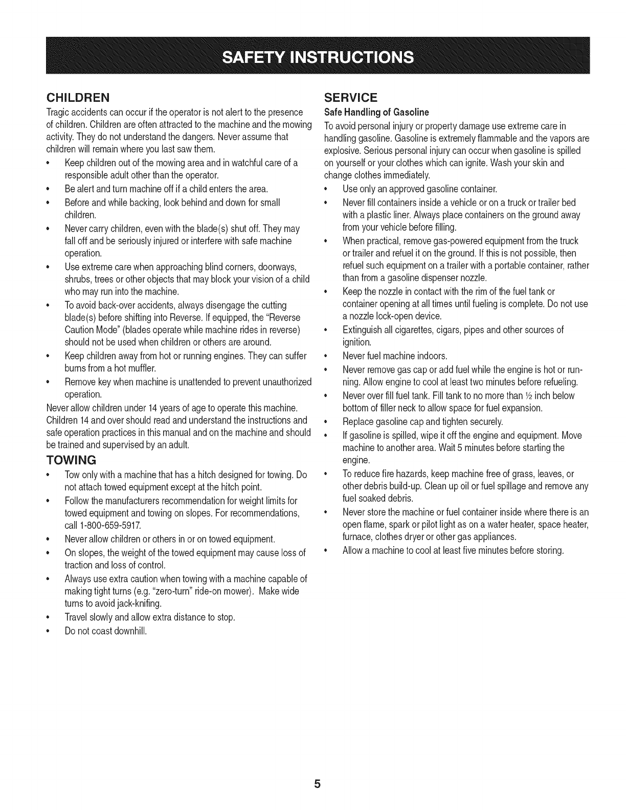
CHILDREN
Tragicaccidentscanoccurifthe operatoris notalert to the presence
of children.Childrenareoftenattractedto the machineandthe mowing
activity.Theydo notunderstandthe dangers.Neverassumethat
childrenwill remainwhereyou lastsawthem.
• Keepchildrenout of the mowingareaand inwatchfulcare of a
responsibleadultotherthanthe operator.
• Bealert andturnmachineoff ifa childentersthe area.
• Beforeandwhilebacking,lookbehindanddownfor small
children.
Nevercarrychildren,evenwiththe blade(s)shutoff.Theymay
fall offandbe seriouslyinjuredorinterferewithsafemachine
operation.
• Useextremecarewhenapproachingblindcorners,doorways,
shrubs,treesorotherobjectsthatmayblockyourvisionof a child
whomayrunintothe machine.
Toavoidback-overaccidents,alwaysdisengagethe cutting
blade(s)beforeshiftingintoReverse.Ifequipped,the "Reverse
CautionMode"(bladesoperatewhilemachineridesinreverse)
shouldnotbe usedwhenchildrenor othersarearound.
Keepchildrenawayfromhotor runningengines.Theycansuffer
burnsfroma hotmuffler.
• Removekeywhenmachineisunattendedto preventunauthorized
operation.
Neverallowchildrenunder14yearsof ageto operatethis machine.
Children14andovershouldreadandunderstandthe instructionsand
safeoperationpracticesinthismanualandon the machineandshould
betrainedandsupervisedbyan adult.
TOWING
Towonlywitha machinethathasa hitchdesignedfor towing.Do
not attachtowedequipmentexceptat the hitchpoint.
Followthe manufacturersrecommendationforweightlimitsfor
towedequipmentandtowingonslopes.For recommendations,
call 1-800-659-5917.
Neverallowchildrenor othersinoron towedequipment.
Onslopes,theweightof thetowedequipmentmaycauselossof
tractionandlossof control.
Alwaysuseextracautionwhentowingwitha machinecapableof
makingtightturns(e.g."zero-turn"ride-onmower). Makewide
turnsto avoidjack-knifing.
Travelslowlyandallowextradistanceto stop.
Do notcoastdownhill.
SERVICE
SafeHandlingof Gasoline
Toavoidpersonalinjuryorpropertydamageuse extremecarein
handlinggasoline.Gasolineisextremelyflammableandthe vaporsare
explosive.Seriouspersonalinjurycanoccurwhengasolineis spilled
on yourselforyour clotheswhichcan ignite.Washyourskinand
changeclothesimmediately.
• Useonly anapprovedgasolinecontainer.
Neverfill containersinsidea vehicleoron a truckortrailer bed
witha plasticliner.Alwaysplacecontainerson the groundaway
fromyourvehiclebeforefilling.
Whenpractical,removegas-poweredequipmentfromthe truck
or trailerandrefueliton theground.Ifthis isnot possible,then
refuelsuchequipmentona trailerwitha portablecontainer,rather
than froma gasolinedispensernozzle.
Keepthe nozzleincontactwiththe rim of the fueltankor
containeropeningat all timesuntilfuelingiscomplete.Donot use
a nozzlelock-opendevice.
Extinguishall cigarettes,cigars,pipesandothersourcesof
ignition.
• Neverfuel machineindoors.
Neverremovegascap or addfuelwhilethe engineis hotor run-
ning.Allowengineto coolat leasttwominutesbeforerefueling.
Neveroverfill fuel tank. Filltankto no morethan 1/2inchbelow
bottomof filler neckto allowspaceforfuel expansion.
• Replacegasolinecap andtightensecurely.
• Ifgasolineis spilled,wipeitoff the engineandequipment.Move
machineto anotherarea.Wait5 minutesbeforestartingthe
engine.
• To reducefire hazards,keepmachinefree of grass,leaves,or
otherdebrisbuild-up.Cleanup oilor fuel spillageandremoveany
fuel soakeddebris.
• Neverstorethe machineor fuelcontainerinsidewherethere isan
openflame,sparkor pilotlight as ona waterheater,spaceheater,
furnace,clothesdryeror othergasappliances.
Allowa machineto coolat leastfiveminutesbeforestoring.
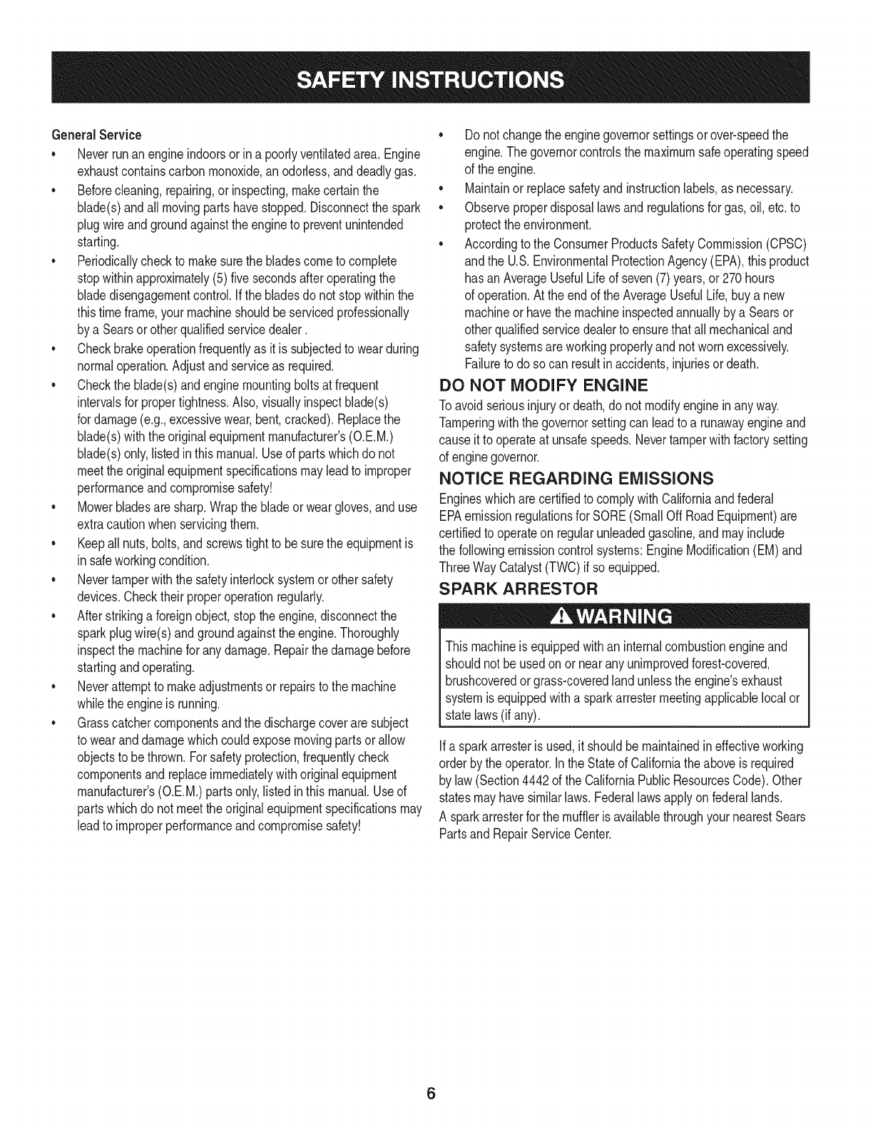
GeneralService
• Neverrunanengineindoorsorinapoorlyventilatedarea.Engine
exhaustcontainscarbonmonoxide,anodorless,anddeadlygas.
• Beforecleaning,repairing,orinspecting,makecertainthe
blade(s)andallmovingpartshavestopped.Disconnectthespark
plugwireandgroundagainsttheenginetopreventunintended
starting.
• Periodicallychecktomakesurethebladescometocomplete
stopwithinapproximately(5)fivesecondsafteroperatingthe
bladedisengagementcontrol.Ifthebladesdonotstopwithinthe
thistimeframe,yourmachineshouldbeservicedprofessionally
byaSearsorotherqualifiedservicedealer.
• Checkbrakeoperationfrequentlyasitissubjectedtowearduring
normaloperation.Adjustandserviceasrequired.
• Checktheblade(s)andenginemountingboltsatfrequent
intervalsforpropertightness.Also,visuallyinspectblade(s)
fordamage(e.g.,excessivewear,bent,cracked).Replacethe
blade(s)withtheoriginalequipmentmanufacturer's(O.E.M.)
blade(s)only,listedinthismanual.Useofpartswhichdonot
meettheoriginalequipmentspecificationsmayleadtoimproper
performanceandcompromisesafety!
• Mowerbladesaresharp.Wrapthebladeorweargloves,anduse
extracautionwhenservicingthem.
• Keepallnuts,bolts,andscrewstighttobesuretheequipmentis
insafeworkingcondition.
• Nevertamperwiththe safetyinterlocksystemor othersafety
devices.Checktheir properoperationregularly.
• Afterstrikinga foreignobject,stopthe engine,disconnectthe
sparkplugwire(s)andgroundagainstthe engine.Thoroughly
inspectthe machinefor anydamage.Repairthe damagebefore
startingandoperating.
• Neverattemptto makeadjustmentsor repairsto the machine
whilethe engineis running.
• Grasscatchercomponentsandthe dischargecoverare subject
to wearanddamagewhichcouldexposemovingpartsor allow
objectsto bethrown.Forsafetyprotection,frequentlycheck
componentsand replaceimmediatelywithoriginalequipment
manufacturer's(O.E.M.)partsonly,listedinthis manual.Useof
partswhichdo not meetthe originalequipmentspecificationsmay
leadto improperperformanceandcompromisesafety!
• Donot changethe enginegovernorsettingsorover-speedthe
engine.The governorcontrolsthe maximumsafeoperatingspeed
of the engine.
Maintainor replacesafetyandinstructionlabels,as necessary.
• Observeproperdisposallawsandregulationsfor gas,oil, etc.to
protecttheenvironment.
• Accordingto the ConsumerProductsSafetyCommission(CPSC)
andthe U.S.EnvironmentalProtectionAgency(EPA),this product
has anAverageUsefulLifeof seven(7)years,or 270hours
of operation.At the endof the AverageUsefulLife,buy anew
machineor havethe machineinspectedannuallybya Searsor
otherqualifiedservicedealerto ensurethatall mechanicaland
safetysystemsareworkingproperlyandnot wornexcessively.
Failureto doso can resultinaccidents,injuriesor death.
DO NOT MODIFY ENGINE
Toavoid seriousinjuryor death,do notmodifyengineinanyway.
Tamperingwiththe governorsettingcanleadto a runawayengineand
causeit to operateat unsafespeeds.Nevertamperwithfactorysetting
of enginegovernor.
NOTICE REGARDING EMISSIONS
Engineswhicharecertifiedto complywithCaliforniaandfederal
EPAemissionregulationsfor SORE(SmallOffRoadEquipment)are
certifiedto operateon regularunleadedgasoline,andmayinclude
the followingemissioncontrolsystems:EngineModification(EM)and
ThreeWayCatalyst(TWO)if so equipped.
SPARK ARRESTOR
Thismachineis equippedwithan internalcombustionengineand
shouldnotbe usedonor nearanyunimprovedforest-covered,
brushcoveredorgrass-coveredlandunlessthe engine'sexhaust
systemisequippedwitha sparkarrestermeetingapplicablelocalor
statelaws(if any).
Ifa sparkarresteris used,it shouldbe maintainedin effectiveworking
orderby the operator.Inthe Stateof Californiatheaboveis required
by law (Section4442of the CaliforniaPublicResourcesCode).Other
statesmayhavesimilarlaws.Federallawsapplyonfederallands.
A sparkarresterfor the mufflerisavailablethroughyournearestSears
PartsandRepairServiceCenter.
6
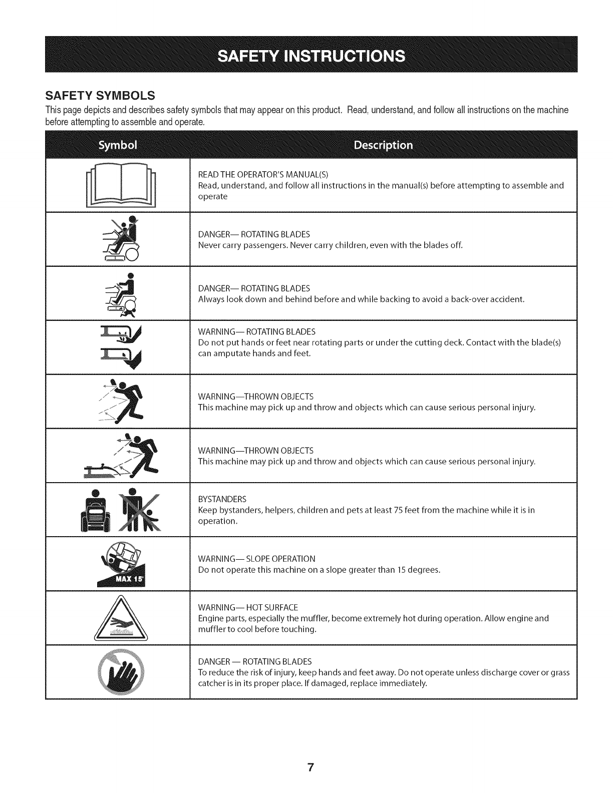
SAFETY SYMBOLS
Thispagedepictsanddescribessafetysymbolsthatmayappearonthis product. Read,understand,andfollowallinstructionson the machine
beforeattemptingto assembleandoperate.
0
A
READ THE OPERATOR'S MANUAL(S)
Read, understand, and follow all instructions in the manual(s) before attempting to assemble and
operate
DANGER-- ROTATING BLADES
Never carry passengers. Never carry children, even with the blades off.
DANGER-- ROTATING BLADES
Always look down and behind before and while backing to avoid a back-over accident.
WARNING-- ROTATING BLADES
Do not put hands or feet near rotating parts or under the cutting deck. Contact with the blade(s)
can amputate hands and feet.
WARNING--THROWN OBJECTS
This machine may pick up and throw and objects which can cause serious personal injury.
WARNING--THROWN OBJECTS
This machine may pick up and throw and objects which can cause serious personal injury.
BYSTANDERS
Keep bystanders, helpers, children and pets at least 75 feet from the machine while it is in
operation.
WARNING-- SLOPE OPERATION
Do not operate this machine on a slope greater than 15 degrees.
WARNING-- HOT SURFACE
Engine parts, especially the muffler, become extremely hot during operation. Allow engine and
muffler to cool before touching.
DANGER-- ROTATING BLADES
To reduce the risk of injury, keep hands and feet away. Do not operate unless discharge cover or grass
catcher is in its proper place. If damaged, replace immediately.
7
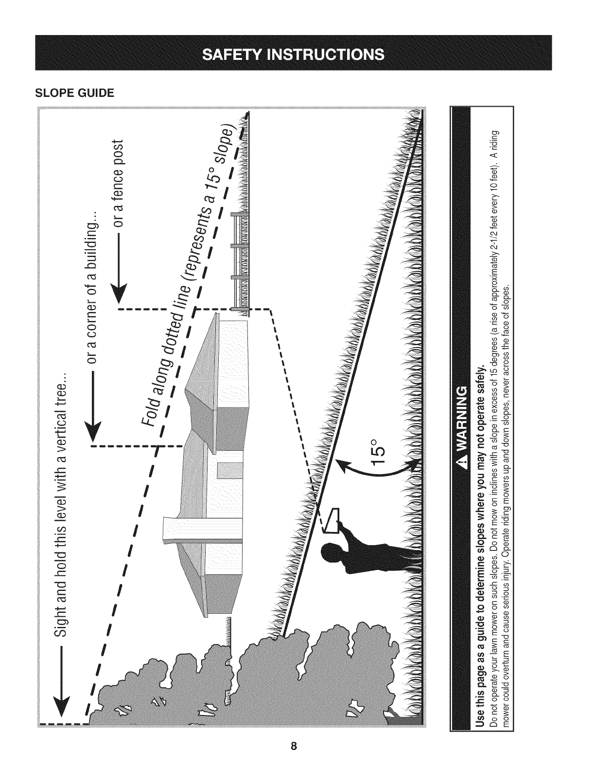
SLOPE GUIDE
}=.==
m
(=)
}====
G.)
1>
0_3
_==
(3)
OO
_==
C:)
_=
_==
0_3
=,F=_
03
_==
c_3
%,==,==
C)
}===
(1)
_==
}==,==
C)
(=3
c_3
}====
C)
_r
Or)
C;)
(=)
(==
CL)
%,==,=
c_3
}====
C)
_r
I
I
I
I
I
I
I
Dm m_
I
Ii
II
II
!I
ll
l
ll
ll
l
0c
E
Q
8
o
(....
"'O
C3,
(1)
(1)
&
1>-.
03
E
x
o
cL (1)
03 cL
o co
"_--- (D
03 O
v_
_2
--_ o
cz o
03 "o
o
_E
(-" 03
o_
CZ3cL
o__
_._o
o
8
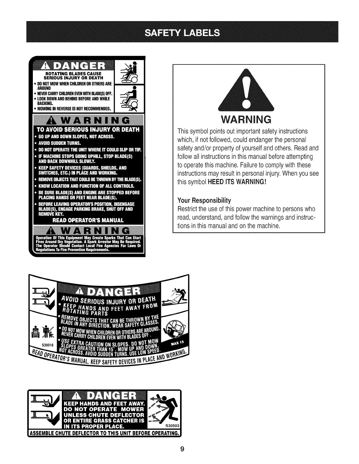
ROTATING BLADES CAUSE
SERIOUS INJURY OR DEATH
DONOTMOWWHENCHILDRENOROTHERSARE
AROUND
NEVERCARRYCHILDRENEVENWITHBLADE(S)OFF.
LOOKDOWNANDBEHINDBEFOREANDWHILE
BACKING.
MOWINGINREVERSEISNOTRECOMMENDED.
WARNING
This symbol points out important safety instructions
which, if notfollowed, could endangerthe personal
safety and/or property of yourself and others. Readand
follow all instructions inthis manualbefore attempting
to operatethis machine. Failureto comply with these
instructions may result in personal injury.When you see
this symbol HEED ITS WARNING!
Your Responsibility
Restrictthe use of this power machineto persons who
read, understand,and follow the warnings and instruc-
tions in this manual and on the machine.
9
IMPORTANT:Yourtractoris shippedwithmotoroil in theengine.
However,you MUSTcheckthe oil levelbeforeoperating.Referto the
Service& Maintenancesectionfor instructionson checkingtheoil
level.
Attaching the Battery Cables
CALIFORNIA PROPOSITION 65
Batteryposts,terminals,andrelatedaccessoriescontainleadand
leadcompounds,chemicalsknownto the Stateof Californiato
causecancerandreproductiveharm.Washhandsafterhandling.
Whenattachingbatterycables,alwaysconnectthe POSITIVE(Red)
wireto its terminalfirst,followedby the NEGATIVE(Black)wire.
Forshippingreasons,bothbatterycablesonyourequipmenthave
beenleftdisconnectedfromthe terminalsat the factory.Toconnect
the batterycables,proceedas follows:
NOTE:Thepositivebatteryterminalis markedPos.(+).The negative
batteryterminalis markedNeg.(-).
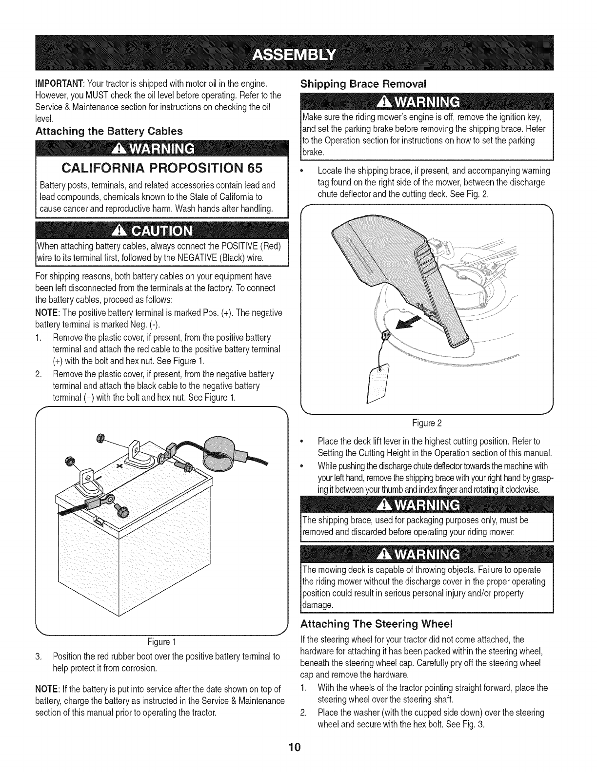
1. Removethe plasticcover,if present,fromthe positivebattery
terminaland attachthe redcableto the positivebatteryterminal
(+)withthe bolt andhexnut.See Figure1.
2. Removethe plasticcover,if present,fromthe negativebattery
terminaland attachthe blackcableto the negativebattery
terminal(-) withthe bolt andhex nut.SeeFigure1.
f
J
Figure1
3. Positionthe redrubberbootoverthe positivebatteryterminalto
helpprotectit fromcorrosion.
NOTE:If thebatteryis put into serviceafterthe dateshownon topof
battery,chargethe batteryas instructedinthe Service& Maintenance
sectionof this manualpriorto operatingthe tractor.
Shipping Brace Removal
Makesurethe ridingmower'sengineis off, removetheignitionkey,
andset the parkingbrakebeforeremovingthe shippingbrace.Refer
Itothe Operationsectionfor instructionsonhowto setthe parking
lbrake.
• Locatethe shippingbrace,if present,andaccompanyingwarning
tag foundonthe rightsideof the mower,betweenthe discharge
chutedeflectorandthe cuttingdeck. SeeFig.2.
//
Figure2
Placethe decklift leverinthe highestcuttingposition.Referto
SettingtheCuttingHeightin the Operationsectionof thismanual.
Whilepushingthedischargechuteddlectortowardsthemachinewith
yourlefthand,removetheshippingbracewithyourrighthandbygrasp-
ingitbetweenyourthumbandindexfingerandrotatingitclockwise.
The shippingbrace,usedfor packagingpurposesonly,mustbe
removedand discardedbeforeoperatingyour ridingmower.
The mowingdeck iscapableof throwingobjects.Failureto operate
the ridingmowerwithoutthe dischargecoverin the properoperating
Ipositioncould resultin seriouspersonalinjuryand/orproperty
ldamage.
Attaching The Steering Wheel
Ifthe steeringwheelfor yourtractordid notcomeattached,the
hardwarefor attachingit has beenpackedwithinthe steeringwheel,
beneaththe steeringwheelcap.Carefullypry off the steeringwheel
cap andremovethe hardware.
1. Withthe wheelsof the tractorpointingstraightforward,placethe
steeringwheeloverthe steeringshaft.
2. Placethe washer(withthe cuppedsidedown)overthe steering
wheeland securewiththe hex bolt.SeeFig.3.
10
f.-
\
Figure3
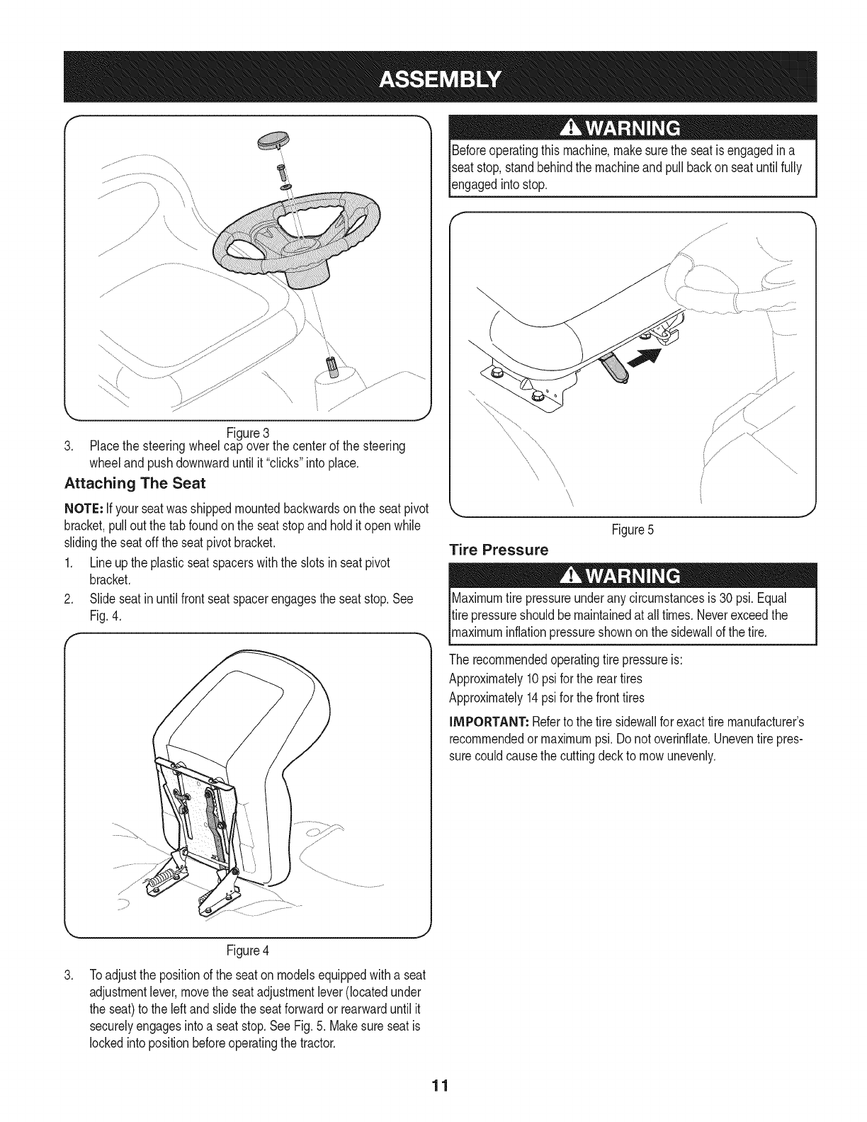
3. Placethe steeringwheelcap overthe centerof the steering
wheeland pushdownwarduntilit "clicks"intoplace.
Attaching The Seat
NOTE: Ifyour seatwasshippedmountedbackwardsonthe seatpivot
bracket,pullout the tab foundonthe seatstopand holdit openwhile
slidingtheseatoff the seatpivotbracket.
1. Lineupthe plasticseatspacerswiththe slotsin seatpivot
bracket.
2. Slideseatinuntilfrontseatspacerengagesthe seatstop.See
Fig.4.
Beforeoperatingthis machine,makesurethe seatis engagedin a
seatstop,standbehindthe machineandpullbackon seatuntil fully
_engagedntostop.
\
\
\
Figure5
Tire Pressure
Maximumtire pressureunderany circumstancesis 30 psi.Equal
tire pressureshouldbe maintainedat all times.Neverexceedthe
_maxmum nfat onpressureshownonthe s dewa of thet re.
The recommendedoperatingtire pressureis:
Approximately10psi forthe reartires
Approximately14psifor the fronttires
iMPORTANT: Referto the tire sidewallfor exacttire manufacturer's
recommendedormaximumpsi.Donot overinfiate.Uneventirepres-
surecouldcausethe cuttingdeckto mowunevenly.
.
Figure4
Toadjustthe positionof the seatonmodelsequippedwitha seat
adjustmentlever,movethe seatadjustmentlever(locatedunder
the seat)to the leftand slidethe seatforwardor rearwarduntil it
securelyengagesintoa seatstop.SeeFig.5. Makesure seatis
lockedinto positionbeforeoperatingthetractor.
11
B
J
A
C
D
E
G
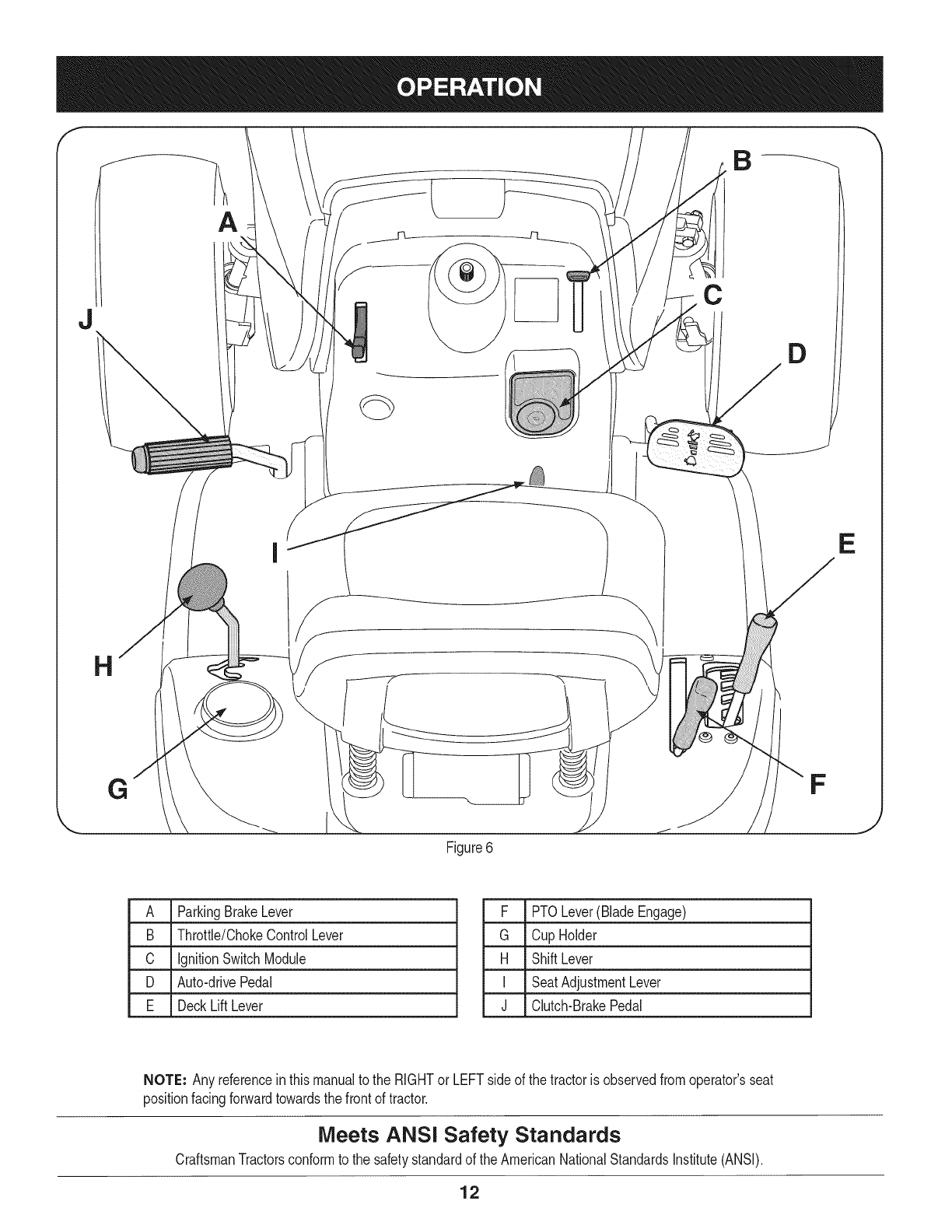
Figure6
F
J
A ParkingBrakeLever
B Throttle/ChokeControlLever
C IgnitionSwitchModule
D Auto-drivePedal
E DeckLift Lever
F PTOLever(BladeEngage)
G Cup Holder
H ShiftLever
I SeatAdjustmentLever
J Clutch-BrakePedal
NOTE: Any referencein thismanualto the RIGHTor LEFTsideof the tractoris observedfromoperator'sseat
positionfacingforwardtowardsthe frontof tractor.
Meets ANSi Safety Standards
CraftsmanTractorsconformto the safetystandardof theAmericanNationalStandardsInstitute(ANSI).
12
PARKING BRAKE LEVER
Toset the parkingbrake: Fullydepressthe brakepedal. Movethe
parkingbrakeleverintothe parkingbrakeposition.Releasethe brake
pedalto allowthe parkingbraketo engage.
To release the parkingbrake: Depressthe brakepedalandthe park-
ingbrakeleverwill moveoutof the parkingbrakepositionon itsown.
Theparkingbrakewillthen bereleased.Releasethe brakepedal.
NOTE=The parkingbrakemustbe setif the operatorleavesthe seat
withthe enginerunningor the enginewill automaticallyshutoff.
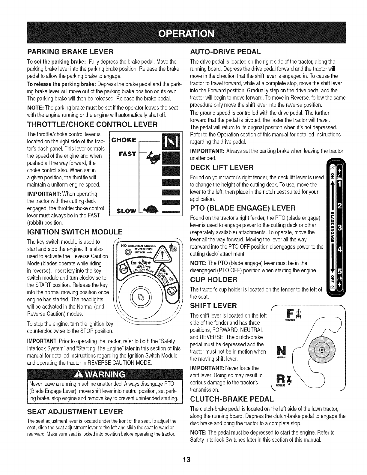
THROTTLE/CHOKE CONTROL LEVER
Thethrottle/chokecontrolleveris
locatedonthe right sideof the trac-
tor'sdash panel.This levercontrols
the speedof the engineand when
pushedall thewayforward,the
chokecontrolalso.Whensetin
a givenposition,thethrottlewill
maintaina uniformenginespeed.
IMPORTANT=Whenoperating
the tractorwiththe cuttingdeck
engaged,thethrottle/chokecontrol
levermustalwaysbe inthe FAST
(rabbit)position.
IGNITION SWITCH MODULE
Thekeyswitchmoduleisusedto
startand stopthe engine.Itis also
usedto activatethe ReverseCaution
Mode(bladesoperatewhileriding
in reverse).Insertkeyinto the key
switchmoduleandturn clockwiseto
the STARTposition.Releasethe key
intothe normalmowingpositiononce
enginehas started.Theheadlights
will beactivatedin the Normal(and
ReverseCaution)modes.
Tostopthe engine,turnthe ignitionkey
counterclockwiseto theSTOPposition.
CHOKE
FAST
SLOW
l=, m
@
IMPORTANT:Priorto operatingthe tractor,referto boththe "Safety
InterlockSystem"and"StartingThe Engine"laterinthissectionof this
manualfor detailedinstructionsregardingthe IgnitionSwitchModule
andoperatingthe tractorinREVERSECAUTIONMODE.
Neverleavea runningmachineunattended.AlwaysdisengagePTO
(BladeEngageLever),moveshiftleverintoneutralposition,setpark-
ingbrake,stopengineandremovekeyto preventunintendedstarting.
SEAT ADJUSTMENT LEVER
Theseatadjustmentleveris locatedunderthe frontofthe seat.Toadjustthe
seat,slidethe seatadjustmentleverto the left andslidethe seatforwardor
rearward.Makesure seatis lockedinto positionbeforeoperatingthetractor.
AUTO-DRIVE PEDAL
The drivepedalislocatedonthe rightside of the tractor,alongthe
runningboard.Depressthe drivepedalforwardandthe tractorwill
moveinthe directionthatthe shiftleveris engagedin. Tocausethe
tractorto travelforward,whileat acompletestop,movethe shift lever
intothe Forwardposition.Graduallysteponthe drivepedalandthe
tractorwill beginto moveforward.Tomovein Reverse,followthe same
procedureonlymovetheshift leverintothe reverseposition.
The groundspeediscontrolledwiththe drivepedal.Thefurther
forwardthatthe pedalis pivoted,thefasterthe tractorwill travel.
The pedalwill returnto its originalpositionwhenit'snot depressed.
Referto the Operationsectionof thismanualfor detailedinstructions
regardingthedrive pedal.
IMPORTANT= Alwayssetthe parkingbrakewhenleavingthe tractor
unattended.
DECK LIFT LEVER
Foundonyour tractor'srightfender,the deckliftleveris used
to changethe heightof the cuttingdeck.To use,movethe
leverto the left, thenplaceinthe notchbestsuitedfor your
application.
PTO (BLADE ENGAGE) LEVER
Foundonthe tractor'srightfender,the PTO(bladeengage)
leveris usedto engagepowerto the cuttingdeckorother
(separatelyavailable)attachments.Tooperate,movethe
leverall thewayforward.Movingthe leverallthe way
rearwardintothe PTOOFFpositiondisengagespowerto the
cuttingdeck/attachment.
NOTE: The PTO(bladeengage)levermustbe inthe
disengaged(PTOOFF)positionwhenstartingthe engine.
CUP HOLDER
The tractor'scup holderis locatedon the fenderto the left of
the seat.
SHIFT LEVER
The shift leveris locatedonthe left
sideof the fenderand hasthree
positions,FORWARD,NEUTRAL
and REVERSE.Theclutch-brake
pedalmustbedepressedandthe
tractormustnot be inmotionwhen
the movingshift lever.
IMPORTANT=Neverforcethe
shiftlever.Doingso mayresultin
seriousdamageto the tractor's
transmission. _J
CLUTCH-BRAKE PEDAL
The clutch-brakepedalis locatedonthe left sideof the lawntractor,
alongthe runningboard.Depressthe clutch-brakepedalto engagethe
disc brakeandbringthe tractorto a completestop.
NOTE=The pedalmustbe depressedto startthe engine.Referto
SafetyInterlockSwitcheslaterin thissectionof thismanual.
13
GAS AND OIL FILL-UP
0il
IMPORTANT: Yourtractorisshippedwithmotoroil inthe engine.
However,you MUSTcheckthe oil levelbeforeoperating.Becareful
notto overfill.
Forinstructionsonhowto checkthe engineoil, referto CheckingThe
EngineOilin the ServiceandMaintenancesectionof this manual.
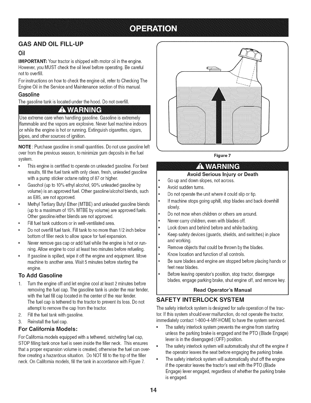
Gasoline
Thegasolinetankis locatedunderthe hood.Do notoverfill.
Useextremecarewhenhandlinggasoline.Gasolineis extremely
flammableandthe vaporsareexplosive.Neverfuel machineindoors
orwhilethe engineis hotor running.Extinguishcigarettes,cigars,
_ppes,andothersourcesof gn t on.
NOTE : Purchasegasolineinsmallquantities.Do notuse gasolineleft
overfromthe previousseason,to minimizegumdepositsin the fuel
system.
• Thisengineis certifiedto operateon unleadedgasoline.For best
results,fill the fueltankwithonlyclean,fresh,unleadedgasoline
witha pumpstickeroctaneratingof 87or higher.
• Gasohol(upto 10%ethylalcohol,90%unleadedgasolineby
volume)is anapprovedfuel.Othergasoline/alcoholblends,such
as E85,arenot approved.
• MethylTertiaryButylEther(MTBE)andunleadedgasolineblends
(upto a maximumof 15%MTBEby volume)are approvedfuels.
Othergasoline/etherblendsare notapproved.
• Fillfuel tankoutdoorsorin well-ventilatedarea.
• Do notoverfillfuel tank. Filltankto no morethan 1/2inch below
bottomof filler neckto allowspacefor fuel expansion.
• Neverremovegas capor addfuel whilethe engineis hot or run-
ning.Allowengineto cool at leasttwo minutesbeforerefueling.
• Ifgasolineis spilled,wipe it off theengineandequipment.Move
machineto anotherarea.Wait5 minutesbeforestartingthe
engine.
To Add Gasoline
1. Turnthe engineoff andlet enginecool at least2 minutesbefore
removingthe fuelcap.The gasolinetankis underthe rearfender,
withthefuel fill cap locatedinthe centerof the rearfender.
Thefuel cap is tetheredto the tractorto preventitsloss. Donot
attemptto removethe cap fromthe tractor.
2. Fillthe fuel tankwithgasoline.
3. Reinstallthe fuelcap.
For California Models:
ForCaliforniamodelsequippedwitha tethered,ratchetingfuelcap,
STOPfillingtankonce fuelis seeninsidethe filler neck. Thisensures
thata properexpansionvolumeis created,otherwisethefuel canover-
flowcreatinga hazardoussituation. Do NOTfill to the top of the filler
neck.On Californiamodels,fill thetank inaccordancewith Figure7.
Figure7
Avoid Serious Injury or Death
* Go upanddownslopes,notacross.
, Avoidsuddenturns.
, Donot operatethe unitwhereit could slipor tip.
, Ifmachinestopsgoinguphill,stopbladesand backdownhill
slowly.
, Donot mowwhenchildrenorothersare around.
, Nevercarrychildren,evenwith bladesoff.
, Lookdownand behindbeforeandwhilebacking.
, Keepsafetydevices(guards,shields,and switches)inplace
andworking.
, Removeobjectsthat couldbethrownby the blades.
, Knowlocationandfunctionof all controls.
, Besurebladesandenginearestoppedbeforeplacinghandsor
feetnearblades.
, Beforeleavingoperator'sposition,stoptractor,disengage
blades,engageparkingbrake,shutengineoff, and removekey.
Read Operator's Manual
SAFETY INTERLOCK SYSTEM
The safetyinterlocksystemis designedfor safeoperationof the trac-
tor.If thissystemshouldevermalfunction,donot operatethe tractor,
immediatelycontact1-800-4-MY-HOMEto havethe systemserviced.
• The safetyinterlocksystempreventsthe enginefromstarting
unlessthe parkingbrakeis engagedandthe PTO(BladeEngage)
leveris inthe disengaged(OFF) position.
• The safetyinterlocksystemwill automaticallyshutoffthe engineif
the operatorleavesthe seatbeforeengagingthe parkingbrake.
• The safetyinterlocksystemwill automaticallyshutoffthe engine
if theoperatorleavesthe tractor'sseatwiththe PTO(Blade
Engage)leverengaged,regardlessof whetherthe parkingbrake
is engaged.
14
REVERSE CAUTION MODE
Useextremecautionwhileoperatingthetractorinthe REVERSE
CAUTIONMODE.Alwayslookdownand behindbeforeandwhile
backing.Do notoperatethe tractorwhenchildrenor othersare
around.Stopthe tractorimmediatelyif someoneentersthe area.
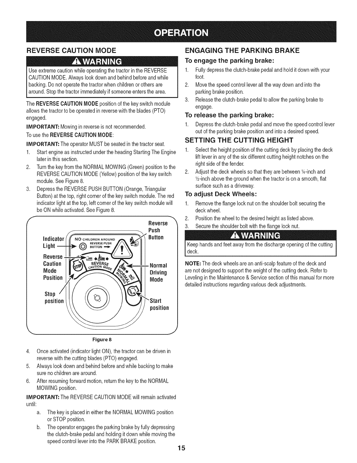
The REVERSECAUTIONMODEpositionof the keyswitchmodule
allowsthe tractorto beoperatedinreversewiththe blades(PTO)
engaged.
iMPORTANT: Mowinginreverseisnot recommended.
Touse the REVERSECAUTIONMODE:
iMPORTANT: The operatorMUSTbeseatedinthe tractorseat.
1. Startengineas instructedunderthe headingStartingThe Engine
laterinthissection.
2. Turnthe keyfromthe NORMALMO%NG (Green)positionto the
REVERSECAUTIONMODE(Yellow)positionof the keyswitch
module.SeeFigure8.
3. Depressthe REVERSEPUSHBUTTON(Orange,Triangular
Button)at the top,rightcornerof the keyswitchmodule.The red
indicatorlight at the top,leftcornerof the keyswitchmodulewill
beON whileactivated.SeeFigure8.
f Reverse "_
Push
Button
indicator
REVERSE PUSH
Light BUTTON=._
Reverse
Caution - Normal
Mode Driving
Position Mode
Stop
position
position
ENGAGING THE PARKING BRAKE
To engage the parking brake:
1. Fullydepressthe clutch-brakepedaland holditdownwithyour
foot.
2. Movethe speedcontrolleverall the waydownandintothe
parkingbrakeposition.
3. Releasethe clutch-brakepedalto allowthe parkingbraketo
engage.
To release the parking brake:
1. Depressthe clutch-brakepedaland movethe speedcontrollever
out of the parkingbrakepositionandintoadesiredspeed.
SETTING THE CUTTING HEIGHT
1. Selectthe heightpositionof the cuttingdeckby placingthe deck
liftleverin anyof the sixdifferentcutting heightnotchesonthe
rightsideof the fender.
2. Adjustthe deck wheelssothattheyarebetween1A-inchand
Y2-inchabovethe groundwhenthe tractoris ona smooth,fiat
surfacesuchas a driveway.
To adjust Deck Wheels:
1. Removethe flangelocknuton the shoulderbolt securingthe
deckwheel.
2. Positionthe wheelto thedesiredheightas listedabove.
3. Securethe shoulderboltwiththe flangelocknut.
Keephandsandfeetawayfromthe dischargeopeningof the cutting
deck.
NOTE: Thedeckwheelsarean anti-scalpfeatureof the deckand
are notdesignedto supportthe weightof the cuttingdeck. Referto
Levelingin the Maintenance& Servicesectionof thismanualfor more
detailedinstructionsregardingvariousdeckadjustments.
'_., j
Figure 8
4. Onceactivated(indicatorlightON),the tractorcan bedrivenin
reversewiththe cuttingblades(PTO)engaged.
5. Alwayslookdownand behindbeforeandwhilebackingto make
surenochildrenarearound.
6. Afterresumingforwardmotion,returnthe keyto the NORMAL
MOWINGposition.
iMPORTANT: The REVERSECAUTIONMODEwill remainactivated
until:
a. Thekeyis placedin eitherthe NORMALMOWINGposition
orSTOPposition.
Theoperatorengagesthe parkingbrakeby fullydepressing
the clutch-brakepedalandholdingit downwhilemovingthe
speedcontrolleverintothe PARKBRAKEposition. 15
STARTING THE ENGINE DRiViNG THE TRACTOR
Do notoperatethe tractorifthe interlocksystemis malfunctioning.
Thissystemwasdesignedfor your safetyandprotection.
NOTE: Referto the Gasolineand Oilfill-upinstructionsearlierinthis
section.
1. Insertthe tractorkeyintothe ignitionswitch.
2. Placethe PTO(BladeEngage)leverinthe disengaged(OFF)
position.
3. Engagethe tractor'sparkingbrake.
4. Activatethe chokecontrolby movingthe throttle/chokeleverall
thewayup intothe chokeposition.
5. Turnthe ignitionkeyclockwiseto the STARTposition.Afterthe
enginestarts,releasethe key.It will returnto the ON (orNormal
Mowing)position.
DO NOTholdthe keyinthe STARTpositionfor longerthanten
secondsat a time.Doingso maycausedamageto yourengine's
electricstarter.
6. Afterthe enginestarts,deactivatethe chokecontroland placethe
throttlecontrolinthe FASTposition.
NOTE: Do NOTleavethechokecontrolonwhileoperatingthe tractor.
Doingso will resultina "rich"fuel mixtureandcausethe engineto run
poorly.
STOPPING THE ENGINE
If youstrikea foreignobject,stopthe engine,disconnectthe spark
plugwire(s)andgroundagainstthe engine.Thoroughlyinspectthe
machinefor anydamage.Repairthe damagebeforerestartingand
operating
1. Ifthe bladesareengaged,placethe PTO(BladeEngage)leverin
thedisengaged(OFF)position.
2. Turnthe ignitionkeycounterclockwiseto the STOPposition.
3. Removethe keyfromthe ignitionswitchto preventunintended
starting.
Avoidsuddenstarts,excessivespeedand suddenstops.
Donot leavethe seatof the tractorwithoutfirst placingthe PTO
(BladeEngage)leverin the disengaged(OFF)position,depressing
the brakepedalandengagingthe parkingbrake.If leavingthe tractor
unattended,also turnthe ignitionkeyoff andremovethe key.
Alwayslook downandbehindbeforeandwhile backingupto avoida
back-overaccident.
1. Depressthe clutch-brakepedalto releasethe parkingbrakeand
then letthe pedalup.
2. Movethethrottleleverintothe FAST(rabbit)position.
3. Placethe shift leverineitherthe FORWARDor REVERSE
position.
IMPORTANT: Do NOTuse the shiftleverto changethedirectionof
travelwhenthe tractoris in motion.Alwaysusethe clutch-brakepedal
to bringthe tractortoa completestopbeforeshifting.
4. Graduallybeginto applypressureto the drivepedal.Thefurther
downthe pedalis pushed,thefasterthe tractorwilltravelinthe
desireddirectionbasedon the positionof the shift lever.
5. The lawntractoris broughtto a stopby releasingthedrive pedal
andthen depressingthe brakepedal.
WARNING!Beforeleavingthe operator'spositionforany reason,
disengagethe blades,placethe shiftleverin neutral,engagethe
parkingbrake,shutengineoff and removethe key.
WHEN stoppingthe tractorforany reasonwhileon a grasssurface,
always:
1. Placethe shift leverinneutral,
2. Engagethe parkingbrake,
3. Shutengineoffand removethe key.Doingso will minimizethe
possibilityof havingyour lawn"browned"byhot exhaustfrom
yourtractor'srunningengine.
16
DRiViNG ON SLOPES
Referto the SLOPEGAUGEinthe SafetyInstructionssectionof the
manualto helpdetermineslopeswhereyou mayoperatethis tractor
safely.
Do notmowon inclineswitha slopein excessof 15degrees(a rise
of approximately2-1/2feetevery10feet). Thetractorcouldoverturn
andcauseseriousinjury.
• Mowupanddownslopes,NEVERacross.
Exerciseextremecautionwhenchangingdirectionon slopes.
Watchfor holes,ruts,bumps,rocks,or otherhiddenobjects.
Uneventerraincouldoverturnthemachine.Tallgrasscan hide
obstacles.
Avoidturnswhendrivingona slope.Ifa turn mustbemade,turn
downthe slope.Turningupa slopegreatlyincreasesthechance
of a rollover.
Avoidstoppingwhendrivingupa slope.Ifit is necessaryto stop
whiledrivingupa slope,start up smoothlyandcarefullyto reduce
the possibilityof flippingthe tractoroverbackward.
ENGAGING THE BLADES
Engagingthe PTO(BladeEngage)transferspowerto the cuttingdeck
orother (separatelyavailable)attachments.Toengagethe blades,
proceedas follows:
1. Movethe throttle/chokecontrolleverto the FAST(rabbit)position.
2. Graspthe PTO(BladeEngage)leverandpivotit all the way
forwardintothe engaged(ON)position.
3. Keepthe throttleleverinthe FAST(rabbit)positionforthe most
efficientuseof thecuttingdeckor other(separatelyavailable)
attachments.
NOTE: The enginewill automaticallyshutoff if the PTOis engaged
withthe shiftleverin positionfor reversetravelwiththe ignitionkeyin
the NORMALMOWINGposition.
MULCHING
A mulchkit is availableasan attachment.Mulchingis a processof
recirculatinggrassclippingsrepeatedlybeneaththe cuttingdeck.The
ultra-fineclippingsarethenforcedbackintothe lawnwheretheyact as
a naturalfertilizer.
A mulchkit canbe purchasedthroughthe retaillocationinwhichyou
purchasedthistractor.For more information, simply contact Sears
at 1-800-4-MY-HOME®.
USING THE DECK LIFT LEVER
Toraisethe cuttingdeck,movethe decklift levertothe left,then place
it in the notchbestsuitedfor yourapplication.Referto SettingThe
CuttingHeightearlierinthis section.
MOWING
Tohelpavoidbladecontactora thrownobjectinjury,keepbystand-
ers,helpers,childrenandpetsat least75feetfromthe machine
while it is in operation.Stopmachineif anyoneentersthe area.
The followinginformationwill be helpfulwhenusingthe cuttingdeck
withyourtractor:
Planyourmowingpatternto avoiddischargeof materialstoward
roads,sidewalks,bystandersandthe like.Also,avoiddischarging
materialagainstawall or obstructionwhichmaycausedischarged
materialto ricochetbacktowardthe operator.
Donot mowat highgroundspeed,especiallyif a mulchkit or
grasscollectoris installed.
• Forbestresultsit is recommendedthatthe first twolaps becut
withthe dischargethrowntowardsthe center.Afterthe firsttwo
laps,reversethedirectionto throwthe dischargeto theoutside
for the balanceof cutting.Thiswill givea betterappearanceto the
lawn.
• Donot cutthe grasstoo short. Shortgrassinvitesweedgrowth
andyellowsquicklyin dry weather.
• Mowingshouldalwaysbedonewiththe engineat full throttle.
• Underheavierconditionsit maybe necessaryto go backoverthe
cut areaa secondtimeto get a cleancut.
• Do NOTattemptto mowheavybrushandweedsandextremely
tall grass.Yourtractoris designedto mowlawns,NOTclear
brush.
• Keepthe bladessharpand replacethe bladeswhenworn.Refer
to CuttingBladesinthe Servicesectionof thismanualfor proper
bladesharpeninginstructions.
HEADLIGHTS
•The lampsare ONwheneverthe tractor'sengineis running.
• The lampsturn OFFwhenthe ignitionkeyis movedto the STOP
position.
17
MAINTENANCE SCHEDULE
Beforeperforminganytypeof maintenance/service,disengageall
controlsandstoptheengine.Waituntilallmovingpartshavecometo
acompletestop.Disconnectsparkplugwireandgrounditagainstthe
enginetopreventunintendedstarting.Alwayswearsafetyglassesduring
operationor whileperforminganyadjustmentsor repairs.
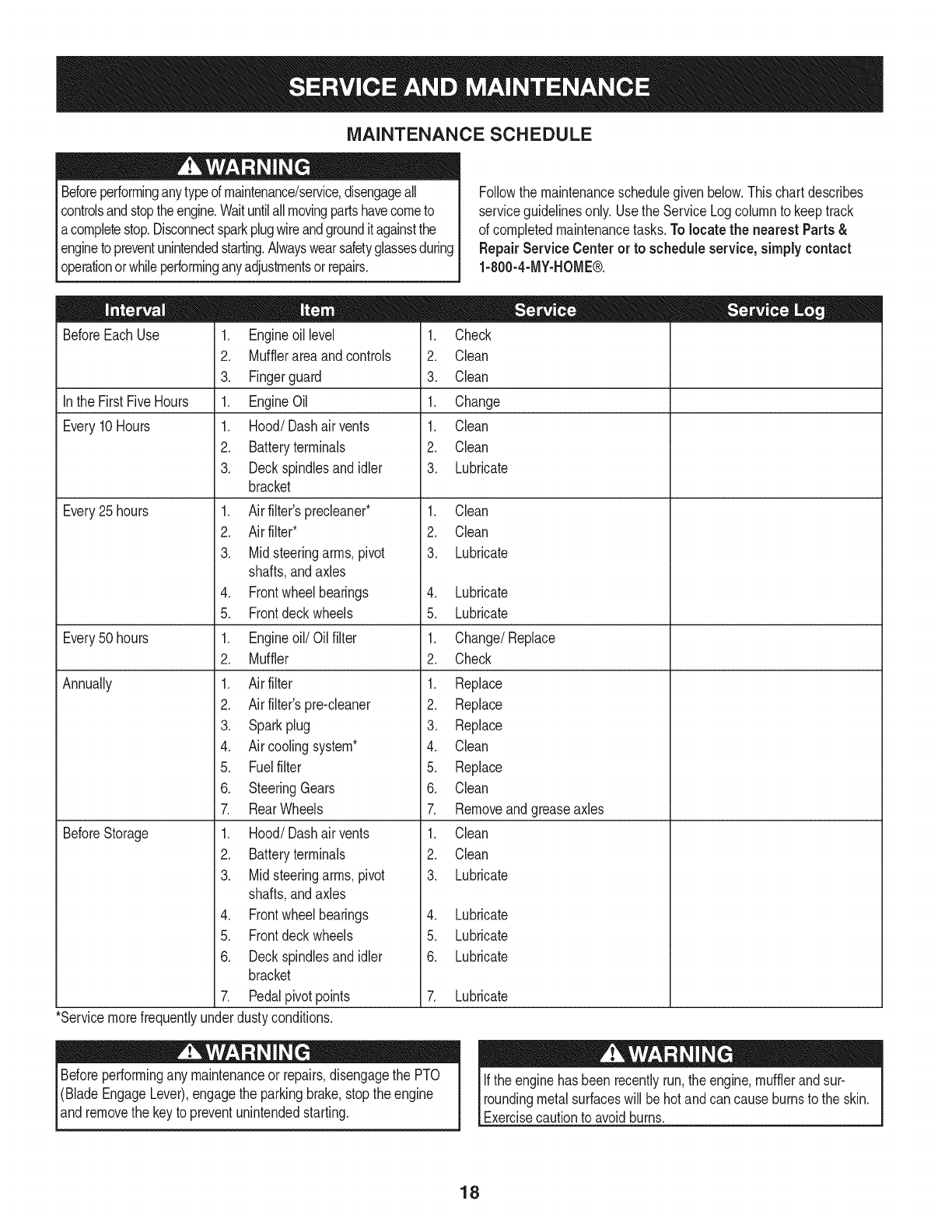
Followthe maintenanceschedulegivenbelow.Thischartdescribes
serviceguidelinesonly.Usethe ServiceLogcolumnto keeptrack
of completedmaintenancetasks.To locate the nearest Parts&
Repair Service Centeror to scheduleservice,simplycontact
1-800-4-MY-HOME®.
BeforeEachUse
In the FirstFiveHours
Every10Hours
Every25 hours
Every50 hours
Annually
BeforeStorage
1. Engineoil level
2. Mufflerareaandcontrols
3. Fingerguard
1. EngineOil
1. Hood/Dashairvents
2. Batteryterminals
3. Deckspindlesand idler
bracket
1. Air filter'sprecleaner*
2. Air filter*
3. Midsteeringarms,pivot
shafts,andaxles
4. Frontwheelbearings
5. Frontdeckwheels
1. Engineoil/Oil filter
2. Muffler
1. Air filter
2. Air filter'spre-cleaner
3. Sparkplug
4. Air coolingsystem*
5. Fuelfilter
6. SteeringGears
7. RearWheels
1. Hood/Dashairvents
2. Batteryterminals
3. Midsteeringarms,pivot
shafts,andaxles
4. Frontwheelbearings
5. Frontdeckwheels
6. Deckspindlesand idler
bracket
7. Pedalpivotpoints
1. Check
2. Clean
3. Clean
1. Change
1. Clean
2. Clean
3. Lubricate
1. Clean
2. Clean
3. Lubricate
4. Lubricate
5. Lubricate
1. Change/Replace
2. Check
1. Replace
2. Replace
3. Replace
4. Clean
5. Replace
6. Clean
7. Removeandgreaseaxles
1. Clean
2. Clean
3. Lubricate
4. Lubricate
5. Lubricate
6. Lubricate
7. Lubricate
*Servicemorefrequentlyunderdustyconditions.
Beforeperformingany maintenanceor repairs,disengagethe PTO
(BladeEngageLever),engagethe parkingbrake,stopthe engine
and removethe keyto preventunintendedstarting.
Ifthe enginehasbeen recentlyrun,the engine,mufflerandsur-
roundingmetalsurfaceswill behotand cancauseburnsto the skin.
Exercisecautionto avoidburns.
18
ENGINE MAINTENANCE
Checking the Engine Oil
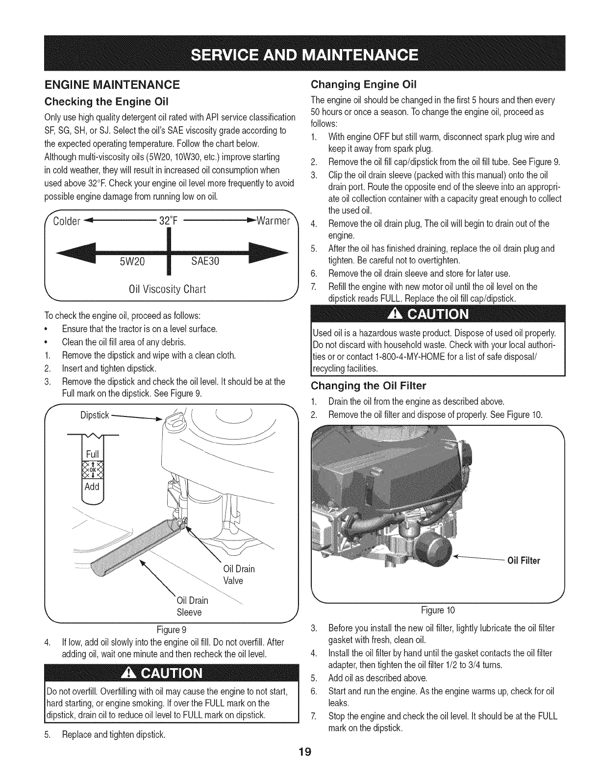
Onlyuse highqualitydetergentoil ratedwithAPIserviceclassification
SF,SG,SH,or SJ, Selectthe oil's SAEviscositygradeaccordingto
the expectedoperatingtemperature.Followthe chartbelow.
Althoughmulti-viscosityoils (5W20,10W30,etc.)improvestarting
in coldweather,theywill resultinincreasedoil consumptionwhen
usedabove32°E Checkyour engineoillevelmorefrequentlyto avoid
possibleenginedamagefromrunninglowonoil.
f'_older _ 32°F _War me'_r
Oil Viscosity Chart
Tocheckthe engineoil, proceedas follows:
• Ensurethatthe tractoris ona levelsurface.
• Cleantheoil fill areaof anydebris.
1. Removethedipstickandwipe withaclean cloth.
2. Insertandtightendipstick.
3. Removethedipstickandcheckthe oil level.It shouldbeat the
Fullmarkonthe dipstick.SeeFigure9.
fDipstick-_
OilDrain
Valve
Oil Drain
Sleeve J
Figure9
If low,addoil slowlyintothe engineoilfill. Do notoverfill.After
addingoil, waitone minuteand then recheckthe oil level.
Donotoverfill.Overfillingwithoil maycausethe engineto not start,
hardstarting,orenginesmoking.If overthe FULLmarkonthe
dipstick,drainoil to reduceoil levelto FULLmarkondipstick.
5. Replaceandtightendipstick.
Changing Engine Oil
The engineoil shouldbechangedinthe first 5 hoursand thenevery
50 hoursoronce a season.Tochangethe engineoil, proceedas
follows:
1. WithengineOFFbut stillwarm,disconnectsparkplugwireand
keepit awayfromsparkplug.
2. Removethe oilfill cap/dipstickfromtheoil fill tube.SeeFigure9.
3. Clipthe oildrainsleeve(packedwiththis manual)ontothe oil
drainport. Routethe oppositeendof the sleeveintoanappropri-
ate oilcollectioncontainerwitha capacitygreatenoughto collect
the usedoil.
4. Removethe oildrainplug,The oilwill begintodrainout of the
engine.
5. Afterthe oil hasfinisheddraining,replacethe oil drainplugand
tighten.Becarefulnot to overtighten.
6. Removethe oildrainsleeveandstorefor later use.
7. Refillthe enginewithnewmotoroil untilthe oil levelonthe
dipstickreadsFULL.Replacetheoil fill cap/dipstick.
Usedoil is a hazardouswasteproduct.Disposeof usedoil properly.
Do notdiscardwithhouseholdwaste.Checkwithyour localauthori-
ties oror contact1-800-4-MY-HOMEfor alist of safedisposal/
recyclingfacilities.
Changing the Oil Filter
1. Drainthe oil fromthe engineas describedabove.
2. Removethe oilfilteranddisposeof properly.See Figure10.
0il Filter
Figure10
3. Beforeyou installthe newoil filter, lightlylubricatethe oil filter
gasketwithfresh,cleanoil.
4. Installthe oil filterbyhanduntilthe gasketcontactstheoil filter
adapter,then tightenthe oilfilter 1/2to 3/4 turns.
5. Addoil as describedabove.
6. Startand runthe engine.Asthe enginewarmsup,checkfor oil
leaks.
7. Stoptheengineandcheckthe oil level.It shouldbeat the FULL
markonthe dipstick.
19
Fuel Filter Air Cleaner
Gasolineand itsvaporsareextremelyflammableandexplosive.Fire
orexplosioncan causesevereburnsor death.
•Keepgasolineawayfromsparks,openflames,pilotlights,heat,
andotherignitionsources.
•Checkfuel lines,tank,cap,andfittingsfrequentlyforcracksor
leaks.Replaceif necessary.
•Beforereplacingthe fuelfilter,drainthe fueltankas perthe
instructionsbelow.
•Do notdrainfuel whenthe engineishot.Allowthe engine
adequatetimeto cool. Drainfuel intoan approvedcontainer
outdoors,awayfromopenflame.
•Drainanylargevolumeof fuelfromthe tankby disconnectingthe
fuel linefromthe in-linefuelfilterneartheengine.
•Removethe fuel linefromthe In-lineside (sidetowardsthe fuel
tank)of thefuel filter.
•Replacementpartsmustbethe sameand installedin the same
positionas theoriginalparts.
•Iffuel spills,waituntil itevaporatesbeforestartingengine.
•Beforereplacingthe fuelfilter,drainthe fueltank. Otherwisefuel
can leakout andcausea fireor explosion.
To Drainthe fuel:
1. Locatethefuelfilter,whichis routedonthe leftsideofthe engine
betweenthe fueltankandthe carburetor,andmaybeattachedto
theenginewitha tie strap.Cutthetie strap,ifpresent,then pinch
thein-lineclamponthefuelfilterwitha pairof pliers,slidethe
clampupthefuelline.Pullthe fuellinefreefromthefilterandplace
theopenendof the lineintoanapprovedcontainerto drainthefuel.
Tochangethe fuel filter:
1. Usepliersto squeezethe tabsonthe otherclamp(theout-line
sideof the fuel filter),thenslidethe clampawayfromthe fuel filter.
Twistandpull the fuellineoff of the fuelfilter.SeeFigure11.
2. Checkthe fuel linesfor cracksor leaks.Replaceif necessary.
3. Replacethe fuel filterwithan originalequipmentreplacement
filter.Call1-800-4-MY-HOME®to purchasethe originalequip-
mentreplacementfilter.
4. Securethe fuel lineswiththe clamps.
Iffilters,or coversare notinstalledcorrectlyseriousinjuryordeath
could resultfrombackfire.Do notattemptto startthe enginewith
themremoved.
Donot use pressurizedair or solventsto cleanthe aircleaner
cartridge.
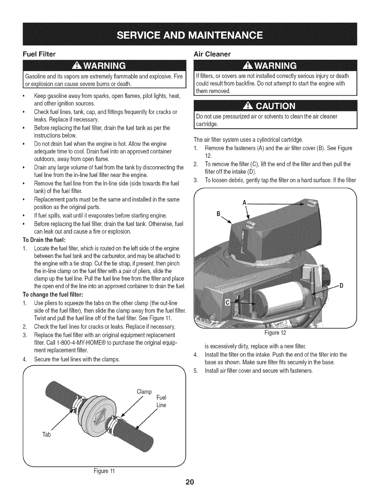
The airfiltersystemusesa cylindricalcartridge.
1. Removethe fasteners(A)andthe airfiltercover(B). SeeFigure
12.
2. To removethe filter(C),liftthe endof the filterandthen pullthe
filteroff the intake(D).
3. To loosendebris,gentlytapthe filteron a hardsurface.If thefilter
A
B
Figure12
is excessivelydirty,replacewitha newfilter.
4. installthe filteronthe intake.Pushthe endof the filterintothe
baseas shown.Makesurefilterfits securelyin the base.
5. installairfiltercoverandsecurewithfasteners.
J
Tab
Clamp Fuel
Line
J
Figure11
2O
Spark Plug
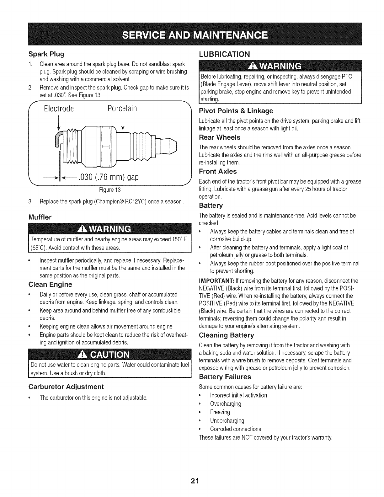
1. Cleanareaaroundthe sparkplugbase.Do notsandblastspark
plug,Sparkplugshouldbecleanedby scrapingorwire brushing
andwashingwitha commercialsolvent
Removeandinspectthe sparkplug.Checkgap to makesureit is
setat .030".See Figure13.
Electrode Porcelain
_.030 (.76 mm) gap
\
Figure13
3. Replacethesparkplug(Champion®RC12YC)once a season.
Muffler
Temperatureof mufflerandnearbyengineareasmayexceed150° F
(65°0).Avoidcontactwiththeseareas.
•inspectmufflerperiodically,and replaceif necessary.Replace-
mentpartsfor the mufflermustbethe sameand installedin the
samepositionas the originalparts.
Clean Engine
•Dailyor beforeeveryuse,cleangrass,chaff oraccumulated
debrisfromengine.Keeplinkage,spring,andcontrolsclean.
Keepareaaroundandbehindmufflerfreeof any combustible
debris.
Keepingenginecleanallowsair movementaroundengine.
• Enginepartsshouldbe keptcleanto reducethe riskof overheat-
ingandignitionof accumulateddebris.
Do notuse waterto cleanengineparts.Watercouldcontaminatefuel
system.Usea brushordry cloth.
Carburetor Adjustment
• Thecarburetoron thisengineisnot adjustable.
LUBRICATION
Beforelubricating,repairing,or inspecting,alwaysdisengagePTO
(BladeEngageLever),moveshift leverinto neutralposition,set
parkingbrake,stopengineandremovekeyto preventunintended
starting.
Pivot Points &Linkage
Lubricateallthe pivotpointsonthe drivesystem,parkingbrakeandlift
linkageat leastonce a seasonwithlightoil.
Rear Wheels
The rearwheelsshouldberemovedfromtheaxlesoncea season.
Lubricatetheaxlesandthe rimswellwithan all-purposegreasebefore
re-installingthem.
Front Axles
Eachend of thetractor'sfrontpivotbar maybeequippedwitha grease
fitting.Lubricatewitha greasegunafterevery25hoursof tractor
operation.
Battery
The batteryis sealedandis maintenance-free.Acidlevelscannotbe
checked.
Alwayskeepthe batterycablesandterminalscleanandfree of
corrosivebuild-up.
Aftercleaningthe batteryandterminals,applya lightcoatof
petroleumjelly orgreaseto bothterminals.
Alwayskeepthe rubberbootpositionedoverthe positiveterminal
to preventshorting.
iMPORTANT: if removingthe batteryfor any reason,disconnectthe
NEGATIVE(Black)wirefromits terminalfirst,followedby the POSI-
TIVE(Red)wire.When re-installingthe battery,alwaysconnectthe
POSITIVE(Red)wire to its terminalfirst,followedbythe NEGATIVE
(Black)wire.Becertainthatthe wiresareconnectedto the correct
terminals;reversingthemcouldchangethe polarityandresultin
damageto yourengine'salternatingsystem.
Cleaning Battery
Cleanthe batteryby removingit fromthe tractorandwashingwith
a bakingsodaandwatersolution.Ifnecessary,scrapethe battery
terminalswitha wirebrushto removedeposits.Coatterminalsand
exposedwiringwithgreaseor petroleumjellyto preventcorrosion.
Battery Failures
Somecommoncausesfor batteryfailureare:
incorrectinitialactivation
Overcharging
Freezing
Undercharging
Corrodedconnections
Thesefailuresare NOTcoveredbyyourtractor'swarranty.
21
CLEANING THE ENGINE AND DECK
Anyfuel oroil spilledonthe machineshouldbewipedoff promptly.Do
NOTallowdebristo accumulatearoundthe coolingfins of the engine
oron anyother partof the machine.
IMPORTANT: The useof a pressurewasherto cleanyourtractoris
NOTrecommended.It maycausedamageto electricalcomponents,
spindles,pulleys,bearingsorthe engine.
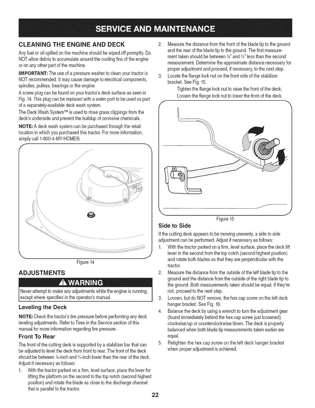
A screwplugcan befoundon yourtractor'sdecksurfaceas seenin
Fig. 14.Thisplugcanbe replacedwitha waterport to beusedas part
of a separately-availabledeckwashsystem.
The DeckWashSystemTM is usedto rinsegrassclippingsfromthe
deck'sundersideandpreventthe buildupof corrosivechemicals.
NOTE: A deckwashsystemcan bepurchasedthroughthe retail
locationinwhichyoupurchasedthistractor.For moreinformation,
simplycall 1-800-4-MY-HOME®.
/
/
Figure14
ADJUSTMENTS
Neverattemptto makeanyadjustmentswhilethe engineis running,
exceptwherespecifiedin the operator'smanual.
Leveling the Deck
NOTE: Checkthe tractor'stire pressurebeforeperforminganydeck
levelingadjustments.Referto Tiresinthe Servicesectionof this
manualfor moreinformationregardingtire pressure.
Front To Rear
Thefrontof the cuttingdeckis supportedby a stabilizerbarthatcan
beadjustedto levelthe deckfromfrontto rear.Thefrontof the deck
shouldbebetween1A-inchand3A-inchlowerthan the rearof thedeck.
Adjustif necessaryas follows:
1. Withthe tractorparkedon a firm,levelsurface,placethe leverfor
liftingthe platformon the secondto the top notch(secondhighest
position)androtatethe bladeas closeto the dischargechannel
thatis parallelto the tractor. 22
2. Measurethedistancefromthe frontof the bladetip to the ground
andthe rearof the bladetip to theground.Thefirst measure-
menttakenshouldbe between1A"and3A"lessthanthe second
measurement.Determinethe approximatedistancenecessaryfor
properadjustmentandproceed,if necessary,to the nextstep.
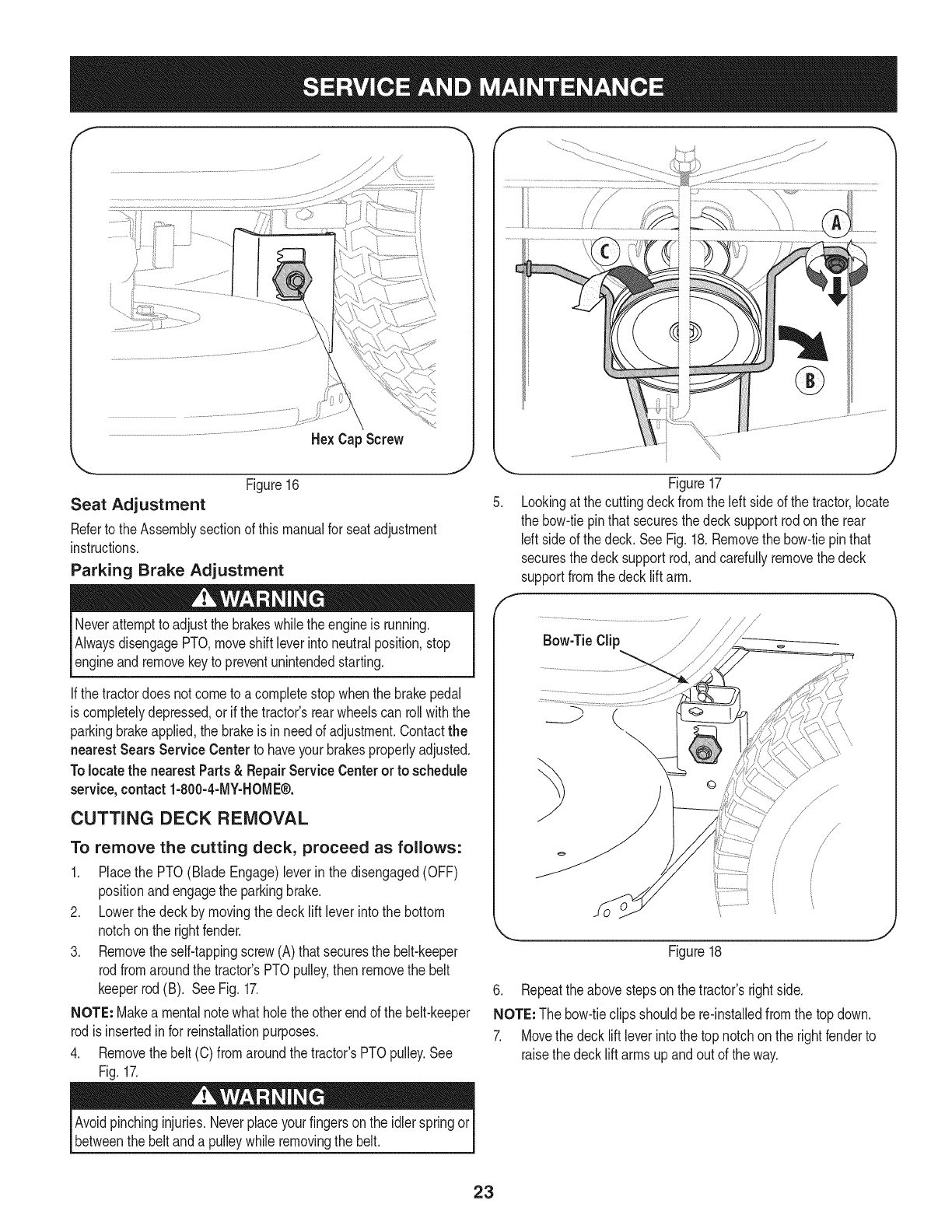
3. Locatethe flangelocknut onthe frontsideof the stabilizer
bracket.SeeFig.15.
Tightenthe flangelocknut to raisethe frontof the deck;
Loosentheflange locknutto lowerthefrontof thedeck.
f
/
Figure15
Side to Side
Ifthe cuttingdeckappearsto be mowingunevenly,a sideto side
adjustmentcan beperformed.Adjustif necessaryas follows:
1. Withthe tractorparkedona firm, levelsurface,placethe decklift
leverin the secondfromthe top notch(secondhighestposition)
and rotatebothbladessothat theyare perpendicularwiththe
tractor.
2. Measurethedistancefromthe outsideof the left bladetip to the
groundandthe distancefromthe outsideof the rightbladetip to
the ground.Bothmeasurementstakenshouldbeequal.Ifthey're
not, proceedto the nextstep.
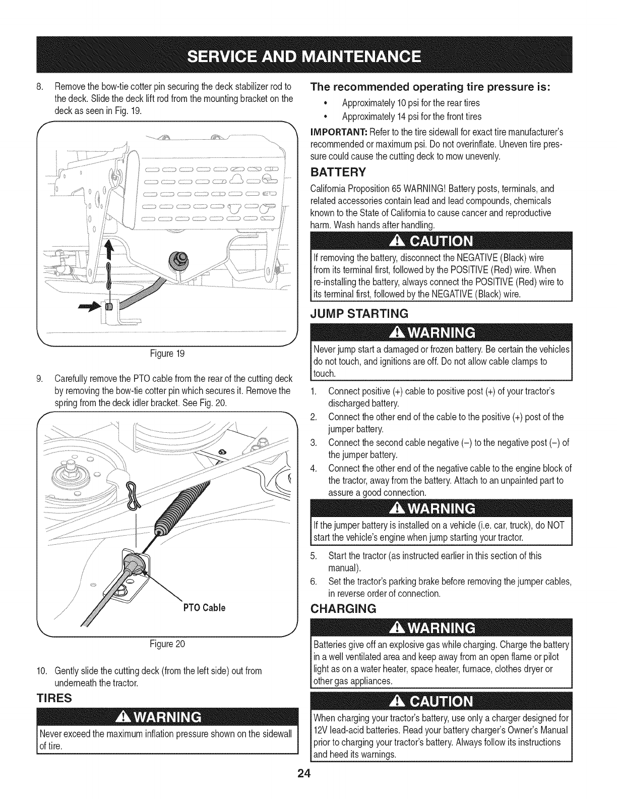
3. Loosen,but do NOTremove,the hexcap screwonthe leftdeck
hangerbracket.SeeFig. 16.
4. Balancethedeckby usinga wrenchto turn theadjustmentgear
(foundimmediatelybehindthehex cap screwjust loosened)
clockwise/uporcounterclockwise/down.Thedeckis properly
balancedwhen bothbladetip measurementstakenearlierare
equal.
5. Retightenthe hex cap screwon the left deck hangerbracket
when properadjustmentis achieved.
He× Cap Screw
'_. ._
Figure16
Seat Adjustment
Referto the Assemblysectionof thismanualfor seatadjustment
instructions.
Parking Brake Adjustment
Neverattemptto adjustthe brakeswhiletheengineis running.
AlwaysdisengagePTO,moveshift leverintoneutralposition,stop
engineandremovekeyto preventunintendedstarting.
If thetractordoes notcometo acompletestopwhenthe brakepedal
is completelydepressed,or if the tractor'srearwheelscan rollwiththe
parkingbrakeapplied,the brakeis in needof adjustment.Contactthe
nearest Sears Service Centerto haveyourbrakesproperlyadjusted.
Tolocatethe nearest Parts& Repair ServiceCenteror to schedule
service,contact 1-800-4-MY-HOME®.
CUTTING DECK REMOVAL
To remove the cutting deck, proceed as follows:
1. Placethe PTO(Blade Engage)leverin the disengaged(OFF)
positionandengagethe parkingbrake.
2. Lowerthe deck by movingthe deck lift lever intothe bottom
notchon the rightfender.
3. Removetheself-tappingscrew(A) thatsecuresthe belt-keeper
rodfromaroundthe tractor'sPTOpulley,thenremovethe belt
keeperrod(B). SeeFig. 17.
NOTE: Makea mentalnotewhatholethe otherendof the belt-keeper
rodisinsertedinfor reinstallationpurposes.
4. Removethebelt (C) from aroundthetractor'sPTOpulley.See
Fig.17.
F
,J
Figure17
Lookingat thecuttingdeckfromthe leftside of the tractor,locate
the bow-tiepinthat securesthedecksupportrodonthe rear
Idt sideof the deck. SeeFig.18.Removethe bow-tiepinthat
securesthedecksupportrod,andcarefullyremovethe deck
supportfromthe decklift arm.
J
Figure18
6. Repeatthe abovestepson the tractor'srightside.
NOTE: The bow-tieclipsshouldbe re-installedfromthe top down.
7. Movethe decklift leverintothe top notchon the rightfenderto
raisethe decklift armsupandout of the way.
Avoidpinchinginjuries.Neverplaceyourfingersonthe idlerspringor
betweenthe belt anda pulleywhile removingthe belt.
23
8, Removethe bow-tiecotterpin securingthe deckstabilizerrodto
thedeck. Slidethe decklift rodfromthe mountingbracketon the
deckasseen in Fig.19.
............./1;_,_......................... /..............................
_... j2
Figure19
.
f
Carefullyremovethe PTOcablefromthe rearof the cuttingdeck
by removingthe bow-tiecotterpinwhichsecuresit. Removethe
springfromthe deckidler bracket.SeeFig.20.
PTOCable
Figure20
10. Gentlyslidethe cuttingdeck(fromthe left side)out from
underneaththe tractor.
TIRES
Neverexceedthe maximuminflationpressureshownonthe sidewall
of tire.
The recommended operating tire pressure is:
• Approximately10psi for the reartires
• Approximately14psi for the fronttires
IMPORTANT: Referto the tire sidewaNfor exacttire manufacturer's
recommendedormaximumpsi.Donot overinflate.Uneventire pres-
surecould causethe cuttingdeckto mowunevenly.
BATTERY
CaliforniaProposition65 WARNING!Batteryposts,terminals,and
relatedaccessoriescontainleadandleadcompounds,chemicals
knownto the Stateof Californiato causecancerandreproductive
harm.Washhandsafter handling.
If removingthe battery,disconnectthe NEGATIVE(Black)wire
fromits terminalfirst,followedbythe POSITIVE(Red) wire.When
relinstallingthe battery,alwaysconnectthe POSITIVE(Red)wire to
Its termna f rst,fo owedby the NEGATVE (Back) w re.
JUMP STARTING
Neverjump starta damagedorfrozenbattery.Becertainthevehicles
do not touch,and ignitionsareoff. Do notallowcable clampsto
touch.
1. Connectpositive(+)cableto positivepost(+)of yourtractor's
dischargedbattery.
2. Connecttheotherendof thecableto the positive(+)postof the
jumperbattery.
3. Connectthesecondcable negative(-) to the negativepost(-) of
the jumperbattery.
4. Connecttheotherendof thenegativecableto the engineblockof
the tractor,awayfromthe battery.Attachto anunpaintedpartto
assurea goodconnection.
Ifthejumper batteryis installedona vehicle(i.e.car,truck),do NOT
startthe vehicle'senginewhenjump startingyourtractor.
5. Startthe tractor(as instructedearlierin thissectionof this
manual).
6. Set the tractor'sparkingbrakebeforeremovingthejumpercables,
in reverseorderof connection.
CHARGING
give offan explosivegas whilecharging.Chargethe batteryI
Batteries
ina wellventilatedareaandkeepawayfroman openflameor pilot
ght as ona waterheater,spaceheater,furnace,c othesdryeror |
othergas appliances. J
Whenchargingyourtractor'sbattery,useonlya chargerdesignedfor I
12Vlead-acidbatteries.Readyourbatterychargers Owners Manual
priorto chargingyourtractors battery.Alwaysfollowits instructions I
land heed ts warnngs. j
24
If yourtractorhasnot beenputinto usefor anextendedperiodof time,
chargethe batteryas follows:
1. Setyour batterychargerto delivera maxof 10amperes.
If yourbatterychargeris automatic,chargethe batteryuntilthe
chargerindicatesthatchargingis complete.Ifthe chargeris not
automatic,chargefor nofewerthaneight hours.
FUSE
One20AMPfuseis installedin yourtractor'swiringharnessto protect
the tractor'selectricalsystemfromdamagecausedbyexcessive
amperage.
If theelectricalsystemdoesnot function,or yourtractor'senginewill
not crank,first checkto be certainthatthe fusehasnot blown.It can
befoundat the rearof the unit,underneaththefenderlocatedby the
battery.
Alwaysusea fusewiththe sameamperagecapacityfor replacement.
CUTTING BLADES
Shutthe engineoff andremoveignitionkeybeforeremovingthe
cuttingblade(s)for sharpeningor replacement.Protectyourhands
by usingheavygloveswhengraspingthe blade.
Periodicallyinspectthe bladeand/or spindlefor cracksordamage,
especiallyafter you'vestrucka foreignobject. Donot operatethe
machineuntil damagedcomponentsare replaced.
Toremovethe blades,proceedas follows.
1. Removethedeckfrombeneaththe tractor,(referto CuttingDeck
Removalearlierinthis section)thengentlyflip thedeckoverto
exposeitsunderside.
2. Placea blockof woodbetweenthe centerdeckhousingbaffle
andthe cuttingbladeto actas a stabilizer.
SeeFig.21.
f
.
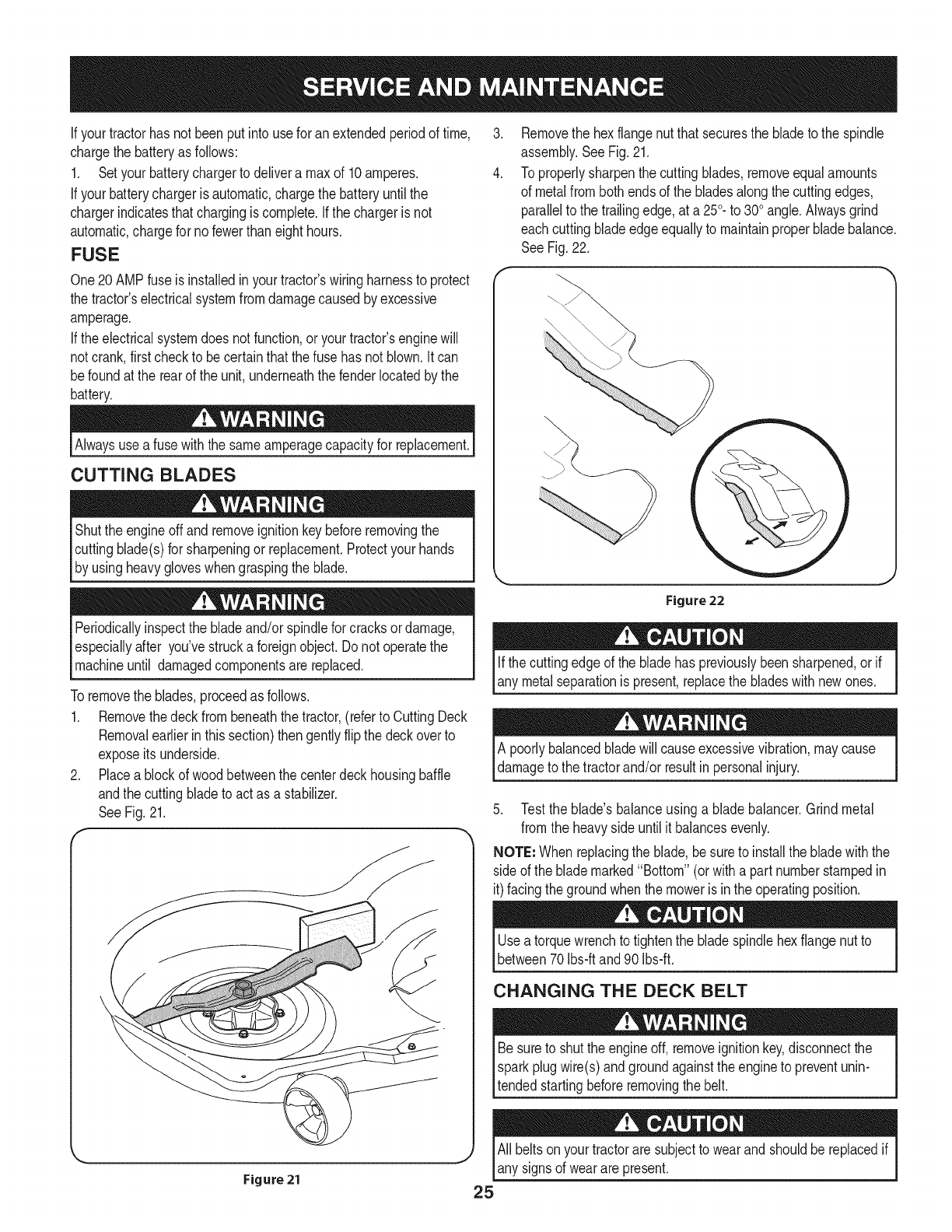
4.
Removethe hexflangenut thatsecuresthe bladeto the spindle
assembly.SeeFig.21.
To properlysharpenthe cuttingblades,removeequalamounts
of metalfrombothendsof the bladesalongthe cuttingedges,
parallelto the trailingedge,at a250.to 300angle.Alwaysgrind
eachcutting bladeedgeequallyto maintainproperbladebalance.
SeeFig.22.
Figure 22
Ifthe cuttingedgeof the bladehas previouslybeensharpened,or if
any metalseparationis present,replacethe bladeswith newones.
A poorlybalancedbladewill causeexcessivevibration,maycause
damageto the tractorand/or resultin personalinjury.
5. Testthe blade'sbalanceusinga bladebalancer.Grindmetal
from the heavyside untilit balancesevenly.
NOTE: Whenreplacingthe blade,be sureto installthe bladewiththe
sideof the blademarked"Bottom"(orwitha part numberstampedin
it)facingthe groundwhenthe moweris inthe operatingposition.
Usea torquewrenchto tightenthe bladespindlehexflangenut to
between70Ibs-ftand 90Ibs-ft.
CHANGING THE DECK BELT
Besureto shutthe engineoff, removeignitionkey,disconnectthe
Isparkplugwire(s)andgroundagainstthe engineto preventunin-
ltended startingbeforeremovingthe belt.
All beltsonyourtractoraresubjectto wearandshouldbereplacedif
any signsof wearare present.
iMPORTANT: The V-beltfoundon yourtractoris speciallydesigned
to engageanddisengagesafely.A substitute(non-OEM)V-beltcan
bedangerousby notdisengagingcompletely.Fora properworking
machine,useidenticalequipmentbeltsas listedinthe partspagesof
thisOperator'sManual.
Tochangeor replacethe deckbelt onyourtractor,proceedas follows:
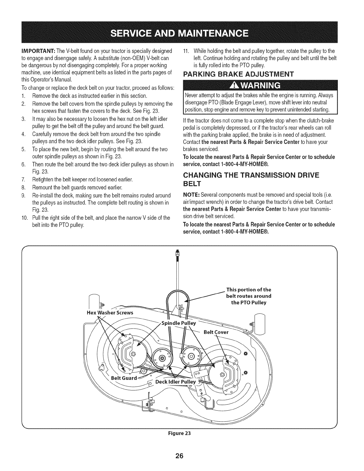
1. Removethe deckas instructedearlierinthis section.
2. Removethe beltcoversfromthe spindlepulleysby removingthe
hexscrewsthatfastenthecoversto the deck.SeeFig.23,
3. It mayalso benecessaryto loosenthe hex nuton the leftidler
pulleyto getthe belt offthe pulleyandaroundthe beltguard.
4. Carefullyremovethe deckbeltfromaroundthe twospindle
pulleysandthetwo deckidlerpulleys,SeeFig,23,
5. Toplacethe newbelt,beginby routingthe belt aroundthe two
outerspindlepulleysas showninFig,23,
6. Thenroutethe beltaroundthe twodeckidlerpulleysas shownin
Fig.23,
7. Retightenthe belt keeperrodloosenedearlier.
8. Remountthebelt guardsremovedearlier,
9. Re-installthedeck, makingsurethe belt remainsroutedaround
the pulleysas instructed.Thecompletebelt routingisshownin
Fig,23.
10. Pullthe rightside ofthe belt,and placethe narrowVside of the
belt intothe PTOpulley.
11. Whileholdingthe belt andpulleytogether,rotatethe pulleyto the
left. Continueholdingand rotatingthe pulleyandbelt untilthe belt
is fullyrolledinto the PTOpulley.
PARKING BRAKE ADJUSTMENT
Neverattemptto adjustthe brakeswhiletheengineis running.Always
disengagePTO(BladeEngageLever),moveshiftleverintoneutral
position,stopengineandremovekeyto preventunintendedstarting.
Ifthe tractordoesnot cometo a completestopwhenthe clutch-brake
pedalis completelydepressed,or if the tractor'srearwheelscan roll
withthe parkingbrakeapplied,the brakeis inneedof adjustment.
Contactthe nearestParts& RepairService Centerto haveyour
brakesserviced.
Tolocatethe nearestParts& RepairServiceCenteror to schedule
service,contact1-800-4-MY-HOME®.
CHANGING THE TRANSMISSION DRIVE
BELT
NOTE: Severalcomponentsmust beremovedandspecialtools(i.e.
air/impactwrench)inorderto changethetractor'sdrivebelt.Contact
the nearest Parts& Repair Service Centerto haveyourtransmis-
sion drivebelt serviced.
Tolocatethe nearestParts& RepairServiceCenteror to schedule
service, contact 1-800-4-MY-HOME®.
He× Washer Screws
This portion of the
belt routes around
the PTO Pulley
Belt Cover
Belt Guard
_ _oo Deck,d,er Pu,,ey
Figure 23
26
Neverstorelawntractorwithfuel intankindoorsor in poorly
ventilatedareaswherefuel fumesmayreachan openflame,spark,
orpilot lightas ona furnace,waterheater,clothesdryer,or gas
appliance.
PREPARING THE ENGINE
IMPORTANT:Fuelleft in thefuel tankduringwarmweatherdeterio-
ratesandwill causeseriousstartingproblems.
To preventgumdepositsfromforminginsidethe engine'scarburetor
andcausingpossiblemalfunctionof theengine,thefuel systemmust
be eithercompletelyemptied,orthe gasolinemustbe treatedwitha
stabilizerto preventdeterioration.
1. Ifusingafuel stabilizer:
a. Readthe productmanufacturer'sinstructionsandrecom-
mendations.
b. Addto clean,freshgasolinethe correctamountof stabilizer
for the capacityof the fuel system.
c. Fillthe fueltankwithtreatedfuel andrunthe enginefor 2-3
minutesto get stabilizedfuel intothe carburetor.
2. Ifemptyingthe fuel system:
a. Donot drainfuel whenthe engineis hot.Allowthe engine
adequatetimeto cool.Drainfuelinto anapprovedcontainer
outdoors,awayfromopenflame.
b. Drainany largevolumeof fuel fromthetank bydisconnect-
ing thefuel linefromthe in-linefuel filternearthe engine.
Seethe completeinstructionsfor DrainingThe Fuellaterin
this section.
Gasolineis extremelyflammableandcan beexplosiveundercertain
conditions.Draingasolinebeforestoringthe equipmentfor extended
periods.Drainfuel only intoanapprovedcontaineroutdoors,away
froman openflame.Allowengineto cool.Extinguishcigarettes,
cigars,pipes,andothersourcesof ignitionpriorto drainingfuel.
Storegasolineinan approvedcontainerinsafelocation.
c. Reconnectthe fuel lineandrunthe engineuntil it startsto
falter,thenuse thechoketo keeptheenginerunninguntilall
fuel in thecarburetorhas beenexhausted.
d. Disconnectthefuel lineanddrainany remaininggasoline
fromthe system.
DRAiNiNG THE FUEL
1. Locatethe fuel filter,whichis locatedonthe leftsideof the
engine,andmaybe attachedto the enginewitha tie strap.
2. Cutthe tie strap,if present,then pinchthe in-lineclamponthe
fuel filterwitha pairof pliers,slidethe clampupthe fuel line.
3. Pullthe fuel linefreefromthe filterandplacethe openendof the
lineintoanapprovedcontainerto drainthe fuel.
PREPARING THE LAWN TRACTOR
1. Cleanandlubricatetractorthoroughlyas describedinthe lubrica-
tion instructions.
2. Donot usea pressurewasheror gardenhoseto cleanyour unit.
3. Storemowerin a dry,cleanarea. Do notstorenextto corrosive
materials,suchas fertilizer.
Gasolineis a toxicsubstance.Disposeof gasolineproperly.Contact
your localauthoritiesfor approveddisposalmethods.
3. Removethe sparkplugandpourone(1)ounceof engineoil
throughthe sparkplugholeintothe cylinder.Cranktheengine
severaltimesto distributethe oil. Replacethe sparkplug.
27
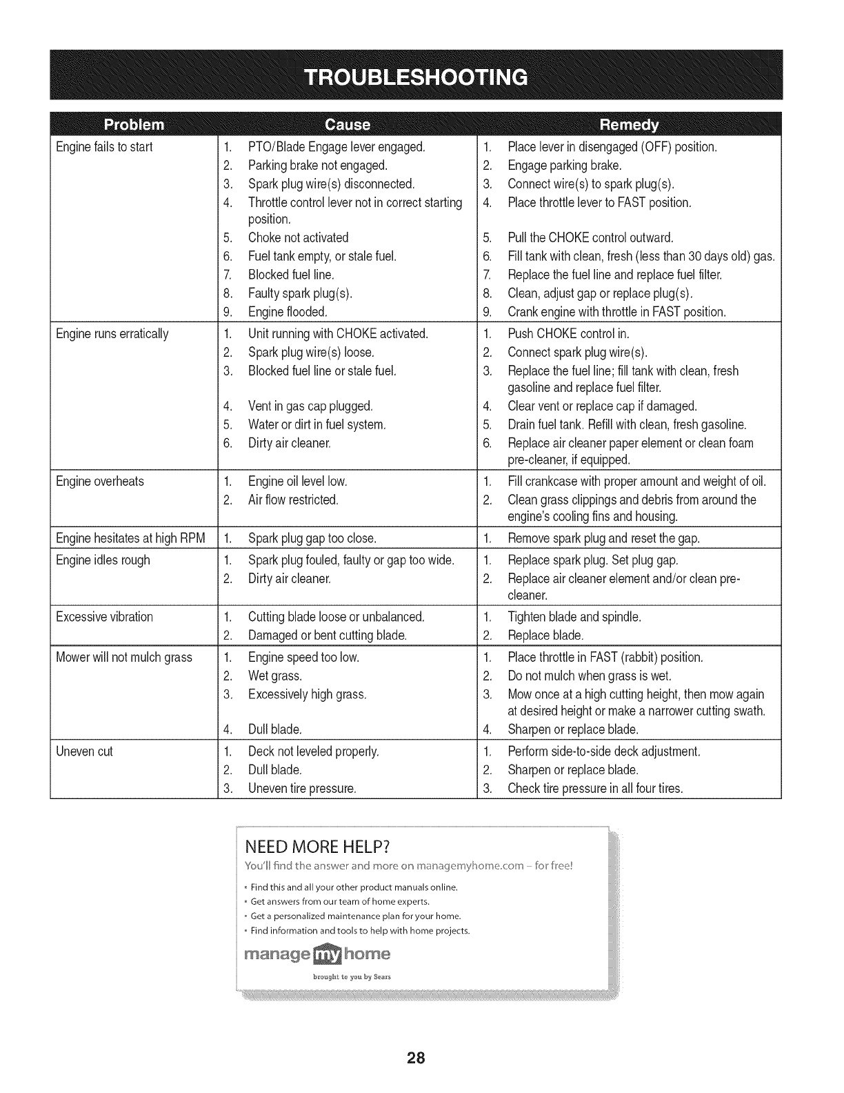
Enginefailsto start
Enginerunserratically
1. PTO/BladeEngageleverengaged.
2. Parkingbrakenotengaged.
3. Sparkplugwire(s)disconnected.
4. Throttlecontrollevernot in correctstarting
position.
5. Chokenotactivated
6. Fueltankempty,or stalefuel.
7. Blockedfuel line.
8. Faultysparkplug(s).
9. Engineflooded.
1. UnitrunningwithCHOKEactivated.
2. Sparkplugwire(s)loose.
3. Blockedfuel lineor stalefuel.
4. Ventingas cap plugged.
5. Waterordirt in fuel system.
6. Dirtyair cleaner.
Engineoverheats 1. Engineoillevellow. 1.
2. Airflowrestricted. 2.
Enginehesitatesat highRPM 1. Sparkpluggaptoo close. 1.
Engineidles rough 1. Sparkplugfouled,faultyor gaptoo wide. 1.
2. Dirtyair cleaner. 2.
Excessivevibration
Mowerwill not mulchgrass
Unevencut
1. Cuttingbladelooseor unbalanced.
2. Damagedor bentcuttingblade.
1. Enginespeedtoo low.
2. Wetgrass.
3. Excessivelyhighgrass.
4. Dullblade.
1. Decknot leveledproperly.
2. Dullblade.
3. Uneventire pressure.
1. Placeleverindisengaged(OFF)position.
2. Engageparkingbrake.
3. Connectwire(s)to sparkplug(s).
4. Placethrottleleverto FASTposition.
5. PulltheCHOKEcontroloutward.
6. Filltankwithclean,fresh(lessthan30 daysold) gas.
7. Replacethe fuel lineandreplacefuel filter.
8. Clean,adjustgapor replaceplug(s).
9. Crankenginewiththrottlein FASTposition.
1. PushCHOKEcontrolin.
2. Connectsparkplugwire(s).
3. Replacethe fuel line;fill tankwithclean,fresh
gasolineandreplacefuel filter.
4. Clearventor replacecap if damaged.
5. Drainfueltank. Refillwithclean,freshgasoline.
6. Replaceair cleanerpaperelementor cleanfoam
pre-cleaner,if equipped.
Fillcrankcasewith properamountandweightof oil.
Cleangrassclippingsanddebrisfromaroundthe
engine'scoolingfinsandhousing.
Removesparkplugandresetthe gap.
Replacesparkplug.Set pluggap.
Replaceair cleanerelementand/orclean pre-
cleaner.
1. Tightenbladeandspindle.
2. Replaceblade.
1. Placethrottlein FAST(rabbit)position.
2. Do notmulchwhengrassis wet.
3. Mowonce at a highcuttingheight,then mowagain
at desiredheightor makea narrowercuttingswath.
4. Sharpenor replaceblade.
1. Performside-to-sidedeckadjustment.
2. Sharpenor replaceblade.
3. Checktire pressureinall fourtires.
NEED MORE HELP?
Youll fkld t_e answe_ _"ct mo_e o_ maoage_nyl]o_ne co_n - br kee!
Find this and all your other product manuals online.
Get answers from our team of home experts.
,, Get a personalized maintenance plan for your home.
,, Find information and tools to help with home projects.
maoage _ home
b_*oug_t t_ _'ou by Sea_'s
28
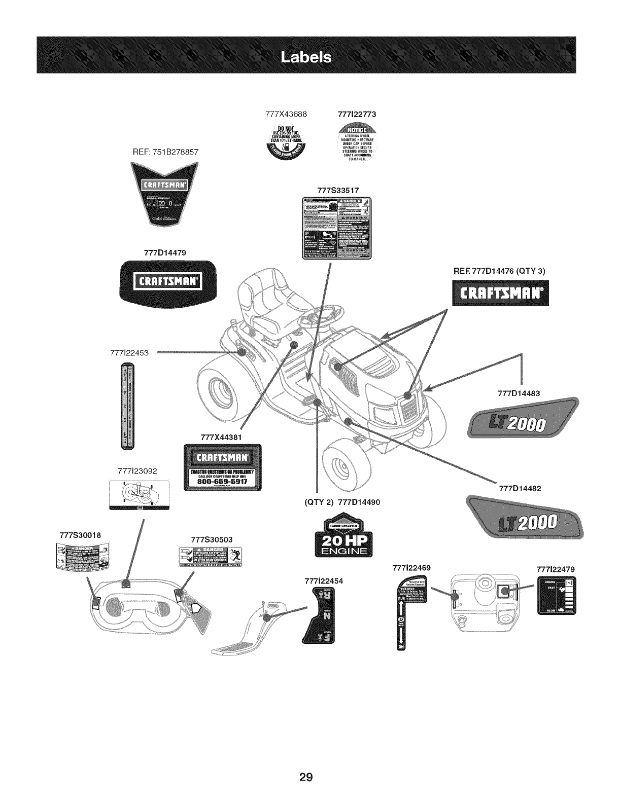
REF: 751 B278857
777X43688 777122773
DO_T
USEE85O_FUEl
CONTAININGMORE STEERINGWHEEL
THAN 10% ETHANOL NOUNTINGHARDWARE
UNDER CAP, BEFORE
OPERATION SECURE
STEERING WHEEL TD
SHAFTACCORDING
TOMANUAL
777S33517
777D14479
REF. 777D14476 (QTY 3)
777122453
777D14483
E
777X44381
777123092
(QTY 2) 777D14490
777D14482
777J22454
777122469 777J22479
29
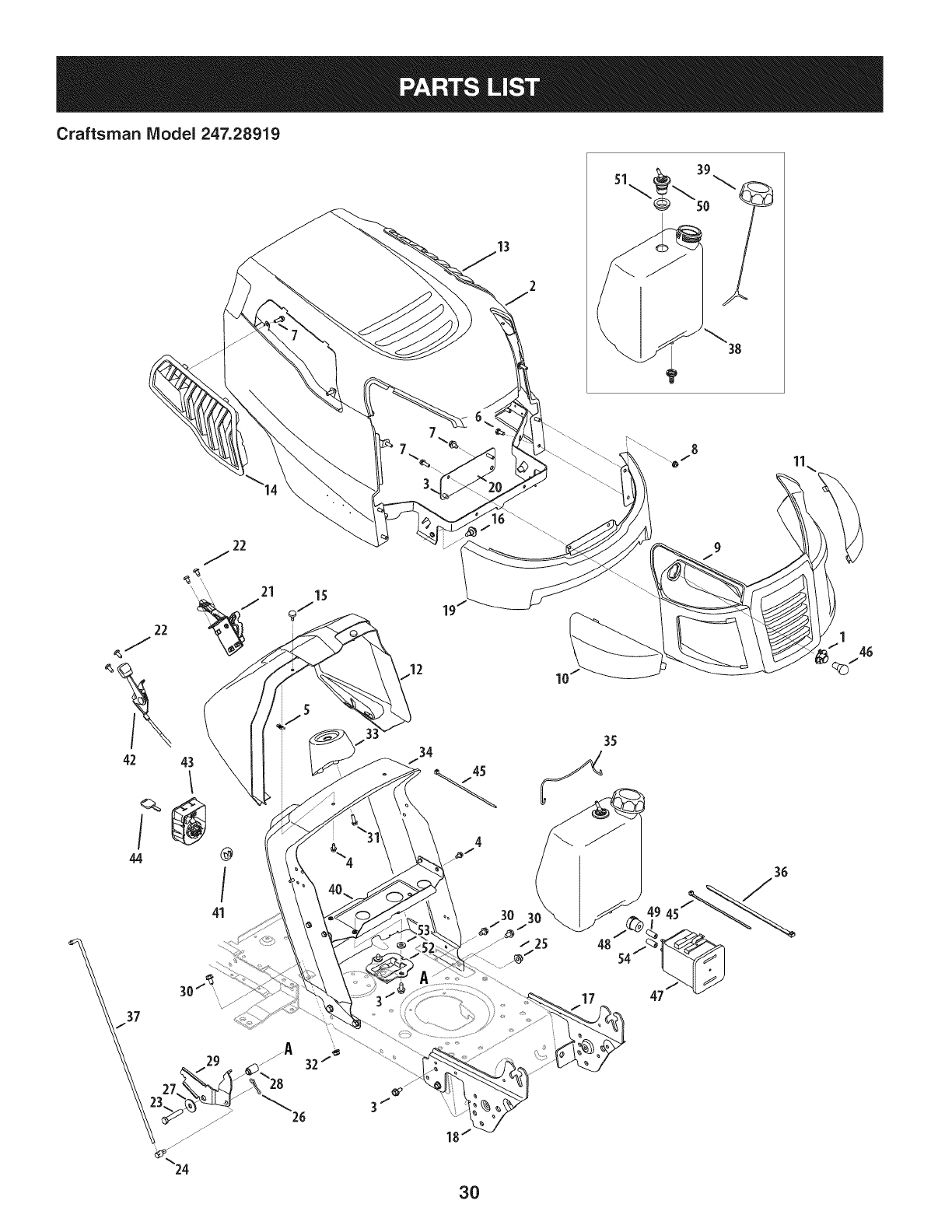
Craftsman Model 247.28919
13
38
34
42 43 I"
44 @
41
30_.....
26
4
3O
3030
/ 25 48
17
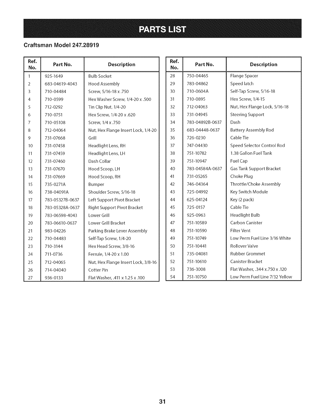
Craftsman Model 247.28919
Ref, [
No,
1 925-1649
2 683-04619-4043
3 710-04484
4 710-0599
5 712-0292
6 710-0751
7 710-05108
8 712-04064
9 731-07668
10 731-07458
II 731-07459
12 731-07460
13 731-07670
14 731-07669
15 735-0271A
16 738-04091A
17 783-05327B-0637
18 783-05328A-0637
19 783-06598-4043
20 783-06610-0637
21 983-04226
22 710-04483
23 710-3144
24 711-0736
25 712-04065
26 714-04040
27 936-0133
Part No, Description
Bulb Socket
Hood Assembly
Screw, 5/16-18 x .750
Hex Washer Screw, 1/4-20 x .500
Tin Clip Nut, 1/4-20
Hex Screw, 1/4-20 x .620
Screw, 1/4 x .750
Nut, Hex Flange Insert Lock, 1/4-20
Grill
Headlight Lens, RH
Headlight Lens, LH
Dash Collar
Hood Scoop, LH
Hood Scoop, RH
Bumper
Shoulder Screw, 5/16-18
Left Support Pivot Bracket
Right Support Pivot Bracket
Lower Grill
Lower Grill Bracket
Parking Brake Lever Assembly
Self-Tap Screw, 1/4-20
Hex Head Screw, 3/8-16
Ferrule, 1/4-20 x 1.00
Nut, Hex Flange Insert Lock, 3/8-16
Cotter Pin
Flat Washer, .411 x 1.25 x .100
Ref, I
No,
28 750-04465
29 783-04862
30 710-0604A
31 710-0895
32 712-04063
33 731-04945
34 783-04892B-0637
35 683-04448-0637
36 726-0230
37 747-04430
38 751-10782
39 751-10947
40 783-04584A-0637
41 731-05265
42 746-04364
43 725-04992
44 625-04124
45 725-0157
46 925-0963
47 751-10589
48 751-10590
49 751-10749
50 751-10441
51 735-04081
52 751-10610
53 736-3008
54 751-10750
Part No, Description
Flange Spacer
Speed latch
Self-Tap Screw, 5/16-18
Hex Screw, 1/4-15
Nut, Hex Flange Lock, 5/16-18
Steering Support
Dash
Battery Assembly Rod
Cable Tie
Speed Selector Control Rod
1.38 Gallon Fuel Tank
Fuel Cap
Gas Tank Support Bracket
Choke Plug
Throttle/Choke Assembly
Key Switch Module
Key (2 pack)
Cable Tie
Headlight Bulb
Carbon Canister
Filter Vent
Low Perm Fuel Line 3/16 White
Rollover Valve
Rubber Grommet
Canister Bracket
Flat Washer, .344 x.750 x .120
Low Perm Fuel Line 7/32 Yellow
31
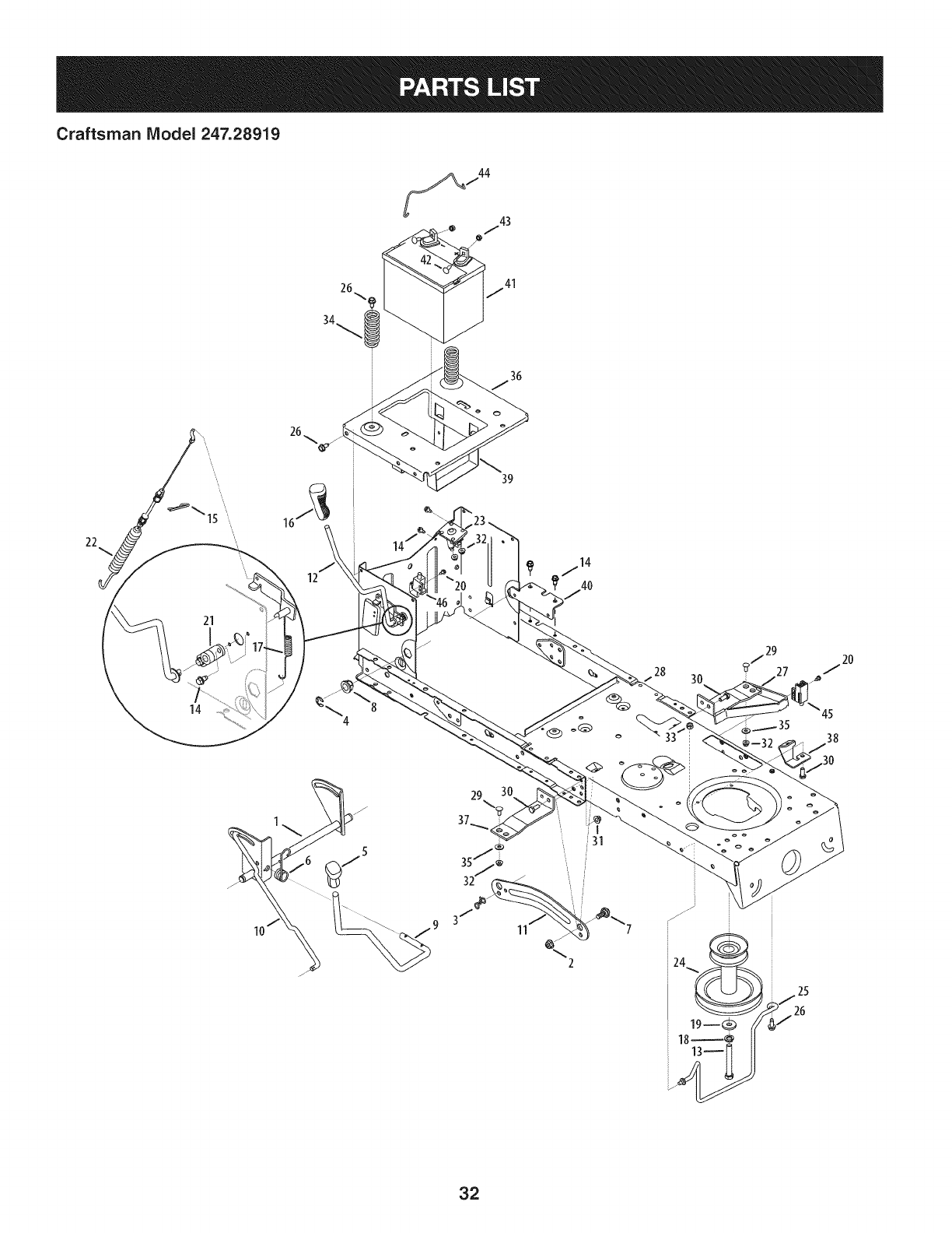
Craftsman IViodel 247.28919
36
22
21
14
12
39
28 3O
45
38
11 %2
32
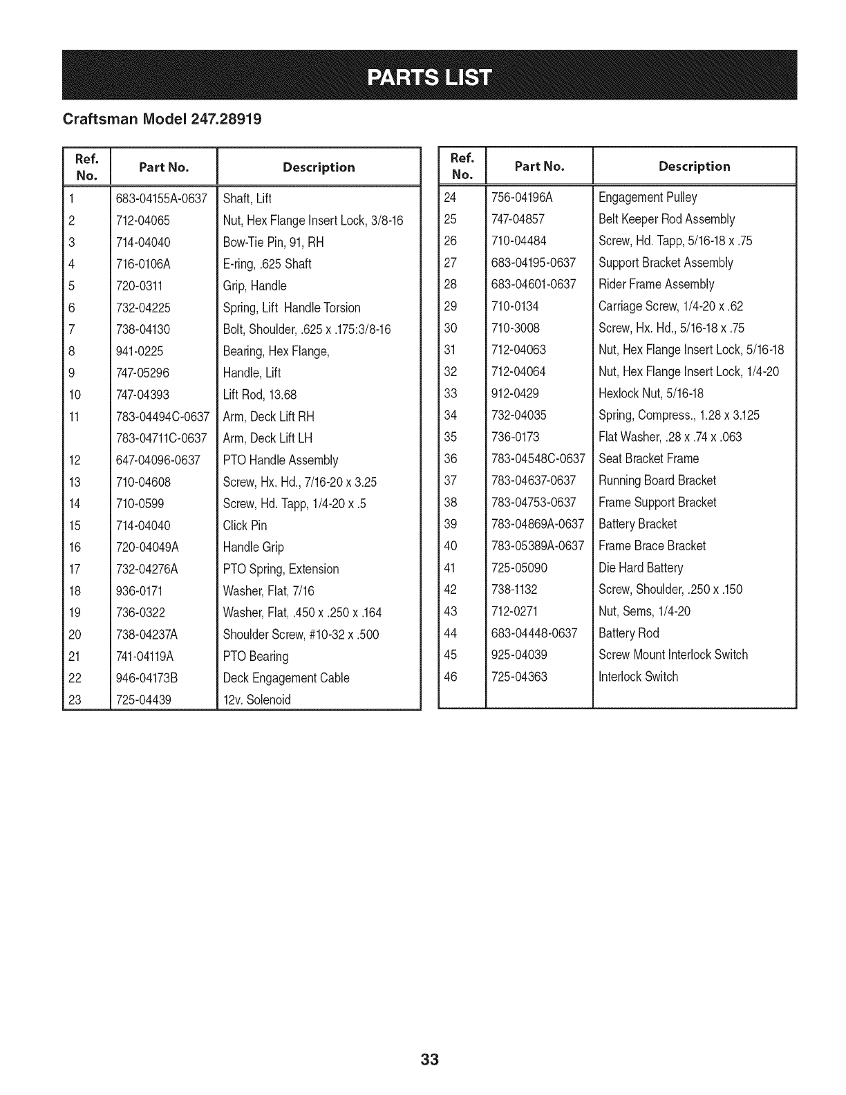
Craftsman IViodel 247.28919
Ref. I
No.
1 683-04155A-0637
2 712-04065
3 714-04040
4 716-0106A
5 720-0311
6 732-04225
7 738-04130
8 941-0225
9 747-05296
10 747-04393
11 783-04494C-0637
783-04711C-0637
12 647-04096-0637
13 710-04608
14 710-0599
15 714-04040
16 720-04049A
17 732-04276A
18 936-0171
19 736-0322
20 738-04237A
21 741-04119A
22 946-04173B
23 725-04439
Part No. Description
Shaft,Lift
Nut, HexFlangeinsertLock,3/8-16
Bow-TiePin,91,RH
E-ring,.625Shaft
Grip,Handle
Spring,Lift HandleTorsion
Bolt,Shoulder,.625x.175:3/8-16
Bearing,HexFlange,
Handle,Lift
Lift Rod,13.68
Arm,DeckLift RH
Arm,DeckLift LH
PTOHandleAssembly
Screw,Hx. Hd.,7/16-20x 3.25
Screw,Hd.lapp, 1/4-20x .5
ClickPin
HandleGrip
PTOSpring,Extension
Washer,Fiat,7/16
Washer,Fiat, .450x.250x.164
ShoulderScrew,#10-32x .500
PTOBearing
DeckEngagementCable
12v.Solenoid
Ref. I
No.
24 756-04196A
25 747-04857
26 710-04484
27 683-04195-0637
28 683-04601-0637
29 710-0134
30 710-3008
31 712-04063
32 712-04064
33 912-0429
34 732-04035
35 736-0173
36 783-04548C-0637
37 783-04637-0637
38 783-04753-0637
39 783-04869A-0637
40 783-05389A-0637
41 725-05090
42 738-1132
43 712-0271
44 683-04448-0637
45 925-04039
46 725-04363
Part No, Description
EngagementPulley
BeltKeeperRodAssembly
Screw,Hd.lapp, 5/16-18x .75
SupportBracketAssembly
RiderFrameAssembly
CarriageScrew,1/4-20x .62
Screw,Hx.Hd.,5/16-18x .75
Nut,HexFlangeInsert Lock,5/16-18
Nut,HexFlangeInsert Lock,1/4-20
HexlockNut,5/16-18
Spring,Compress.,1.28x 3.125
FiatWasher,.28x.74x.063
Seat BracketFrame
RunningBoardBracket
FrameSupportBracket
BatteryBracket
FrameBraceBracket
DieHard Battery
Screw,Shoulder,.250x.150
Nut,Seres,1/4-20
BatteryRod
ScrewMountInterlockSwitch
interlockSwitch
33
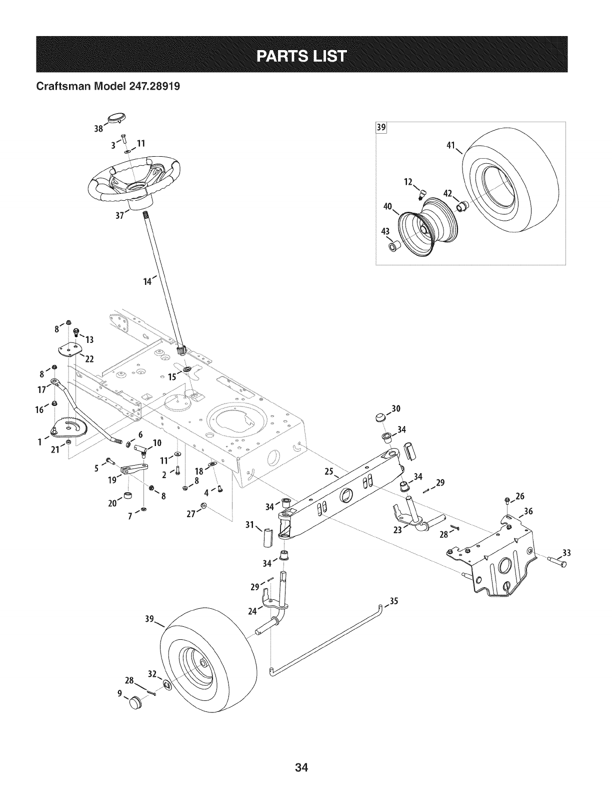
Craftsman IViodel 247.28919
41\_
28 32!
25
34
33
34
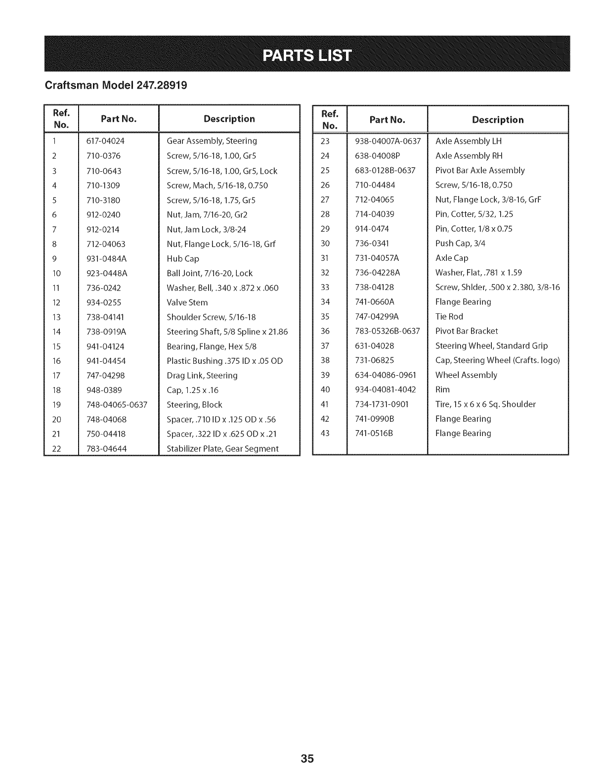
Craftsman Model 247.28919
Ref, I
No,
1 617-04024
2 710-0376
3 710-0643
4 710-1309
5 710-3180
6 912-0240
7 912-0214
8 712-04063
9 931-0484A
10 923-0448A
II 736-0242
12 934-0255
13 738-04141
14 738-0919A
15 941-04124
16 941-04454
17 747-04298
18 948-0389
19 748-04065-0637
20 748-04068
21 750-04418
22 783-04644
Part No. Description
Gear Assembly, Steering
Screw, 5/16-18, 1.00, Gr5
Screw, 5/16-18, 1.00, Gr5, Lock
Screw, Mach, 5/16-18, 0.750
Screw, 5/16-18, 1.75, Gr5
Nut, Jam, 7/16-20, Gr2
Nut, Jam Lock, 3/8-24
Nut, Flange Lock, 5/16-18, Grf
Hub Cap
Ball Joint, 7/16-20, Lock
Washer, Bell, .340 x .872 x .060
Valve Stem
Shoulder Screw, 5/16-18
Steering Shaft, 5/8 Spline x 21.86
Bearing, Flange, Hex 5/8
Plastic Bushing .375 ID x .05 OD
Drag Link, Steering
Cap, 1.25 x .16
Steering, Block
Spacer, .710 ID x .125 OD x .56
Spacer, .322 ID x .625 OD x .21
Stabilizer Plate, Gear Segment
Ref, I
No,
23 938-04007A-0637
24 638-04008P
25 683-0128B-0637
26 710-04484
27 712-04065
28 714-04039
29 914-0474
30 736-0341
31 731-04057A
32 736-04228A
33 738-04128
34 741-0660A
35 747-04299A
36 783-05326B-0637
37 631-04028
38 731-06825
39 634-04086-0961
40 934-04081-4042
41 734-1731-0901
42 741-0990B
43 741-0516B
Part No, Description
Axle Assembly LH
Axle Assembly RH
Pivot Bar Axle Assembly
Screw, 5/16-18, 0.750
Nut, Flange Lock, 3/8-16, GrF
Pin, Cotter, 5/32, 1.25
Pin, Cotter, 1/8 x 0.75
Push Cap, 3/4
Axle Cap
Washer, Flat, .781 x 1.59
Screw, Shlder, .500 x 2.380, 3/8-16
Flange Bearing
Tie Rod
Pivot Bar Bracket
Steering Wheel, Standard Grip
Cap, Steering Wheel (Crafts. logo)
Wheel Assembly
Rim
Tire, 15 x6x6 Sq. Shoulder
Flange Bearing
Flange Bearing
35
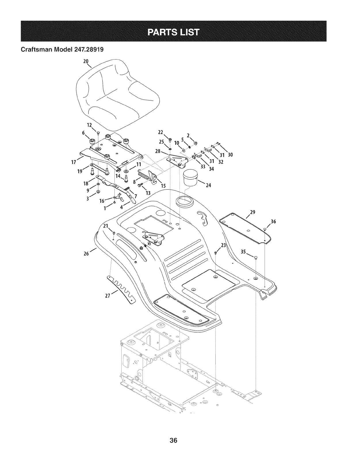
Craftsman Model 247.28919
2o
12
6, 22
2S\
28.. 31 30
17 32
15
oi
29
/
3G
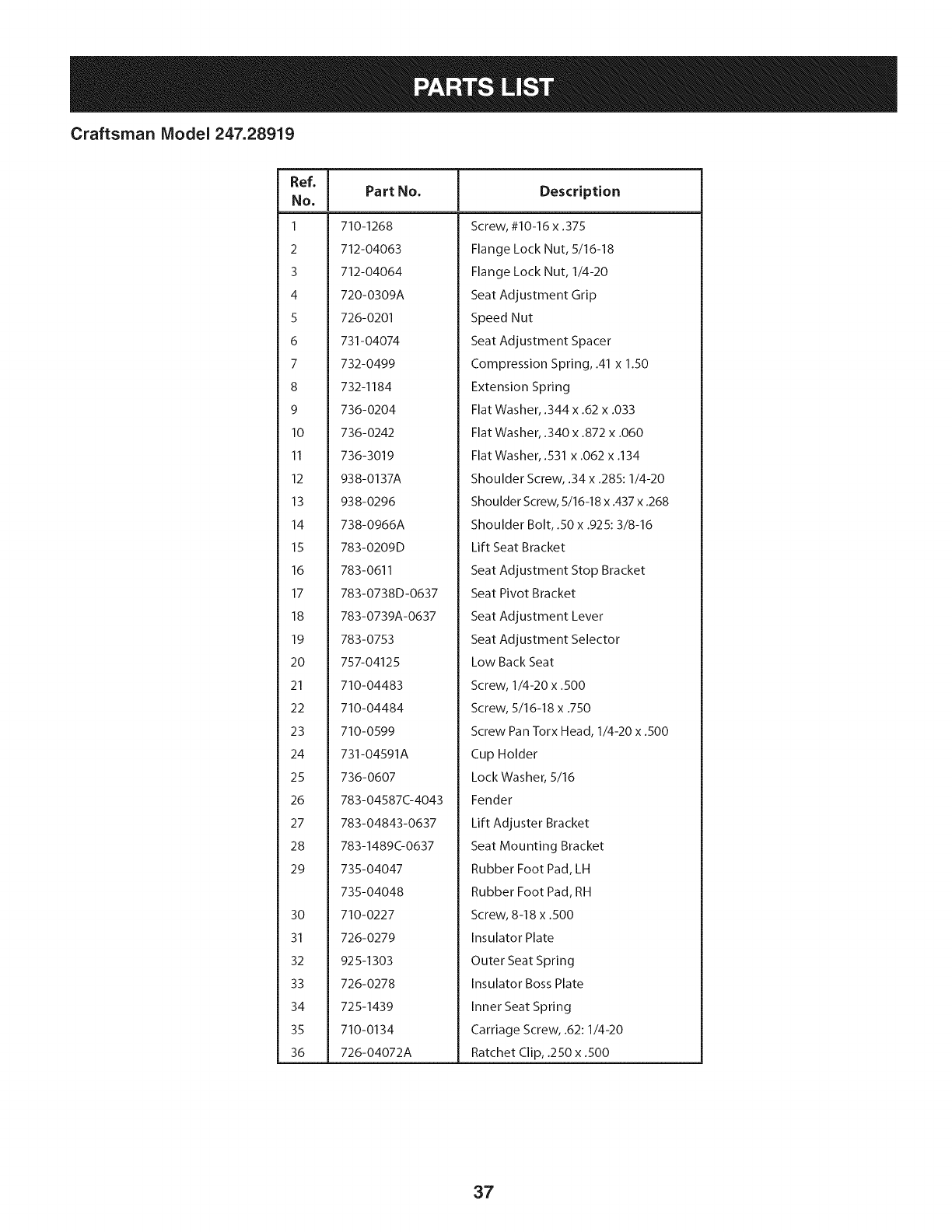
Craftsman Model 247.28919
Ref, [
No,
1 710-1268
2 712-04063
3 712-04064
4 720-0309A
5 726-0201
6 731-04074
7 732-0499
8 732-1184
9 736-0204
10 736-0242
II 736-3019
12 938-0137A
13 938-0296
14 738-0966A
15 783-0209D
16 783-0611
17 783-0738D-0637
18 783-0739A-0637
19 783-0753
20 757-04125
21 710-04483
22 710-04484
23 710-0599
24 731-04591A
25 736-0607
26 783-04587C-4043
27 783-04843-0637
28 783-1489G0637
29 735-04047
735-04048
30 710-0227
31 726-0279
32 925-1303
33 726-0278
34 725-1439
35 710-0134
36 726-04072A
Part No, Description
Screw, #10-16 x .375
Flange Lock Nut, 5/16-18
Flange Lock Nut, 1/4-20
Seat Adjustment Grip
Speed Nut
Seat Adjustment Spacer
Compression Spring, .41 x 1.50
Extension Spring
Flat Washer, .344 x .62 x .033
Flat Washer, .340 x .872 x .060
Flat Washer, .531 x .062 x .134
Shoulder Screw, .34 x .285:1/4-20
Shoulder Screw, 5/16-18 x .437 x .268
Shoulder Bolt, .50 x .925:3/8-16
Lift Seat Bracket
Seat Adjustment Stop Bracket
Seat Pivot Bracket
Seat Adjustment Lever
Seat Adjustment Selector
Low Back Seat
Screw, 1/4-20 x .500
Screw, 5/16-18 x .750
Screw Pan Torx Head, 1/4-20 x .500
Cup Holder
Lock Washer, 5/16
Fender
Lift Adjuster Bracket
Seat Mounting Bracket
Rubber Foot Pad, LH
Rubber Foot Pad, RH
Screw, 8-18 x .500
Insulator Plate
Outer Seat Spring
Insulator Boss Plate
Inner Seat Spring
Carriage Screw, .62:1/4-20
Ratchet Clip, .250 x .500
37
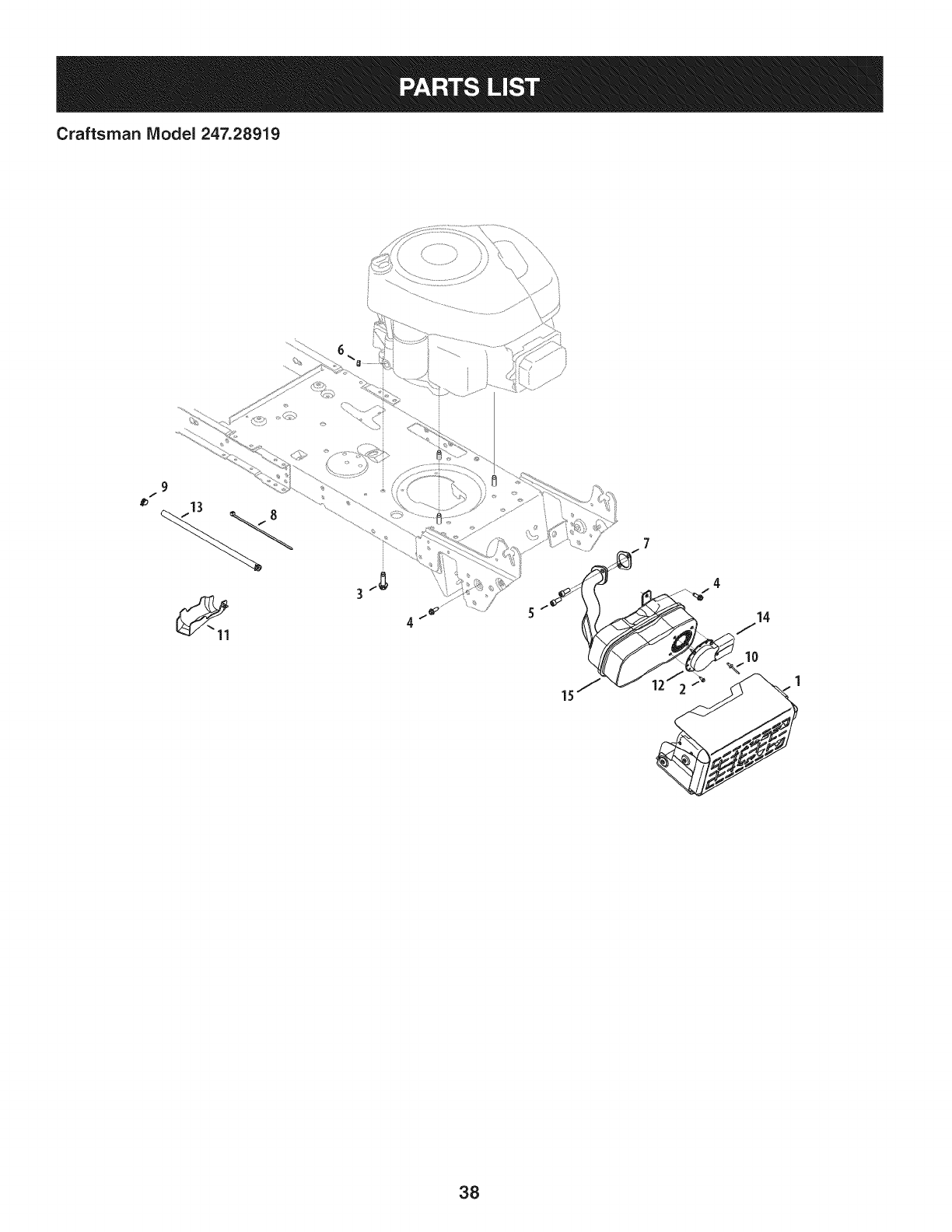
Craftsman IViodel 247.28919
9
f
4
7
4
14
10
1
38
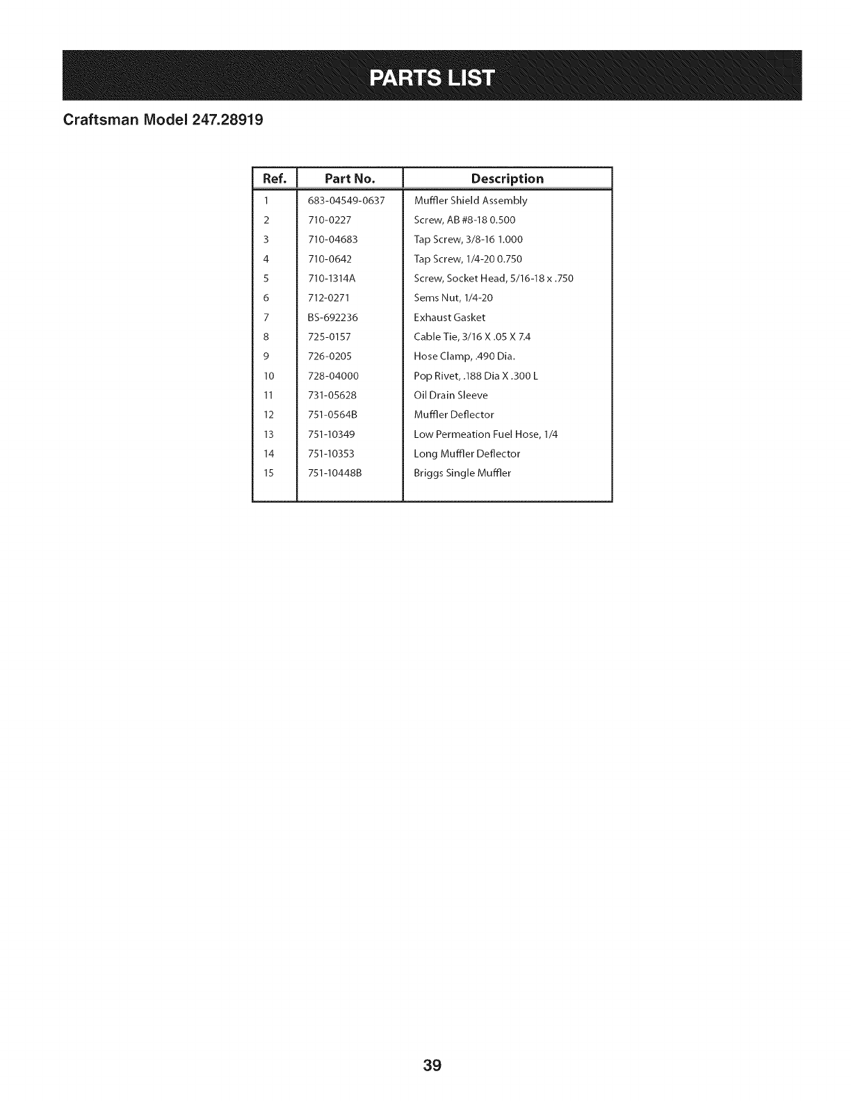
Craftsman Model 247.28919
I
Ref, IPart No.
1 683-04549-0637
2 710-0227
3 710-04683
4 710-0642
5 710-1314A
6 712-0271
7BS-692236
8 725-0157
9 726-0205
l0 728-04000
II 731-05628
12 751-0564B
13 751-I0349
14 751-I0353
15 751-I0448B
Description
Muffler Shield Assembly
Screw, AB #8-18 0.500
Tap Screw, 3/8-16 h000
Tap Screw, 1/4-20 0.750
Screw, Socket Head, 5/16-18 x .750
Sems Nut, 1/4-20
Exhaust Gasket
Cable Tie, 3/16 X .05 X Z4
Hose Clamp, .490 Dia.
Pop Rivet, .188 Dia X .300 L
Oil Drain Sleeve
Muffler Deflector
Low Permeation Fuel Hose, 1/4
Long Muffler Deflector
Briggs Single Muffler
39
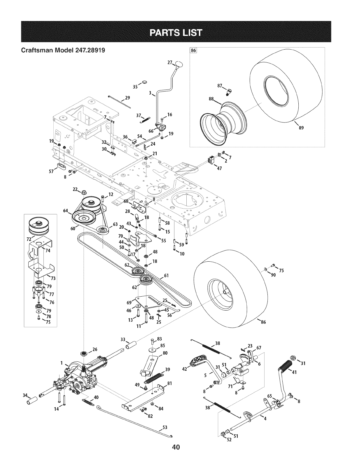
Craftsman IViodel 247.28919
29
24
30_ 21
\89
_7!
64
14
28
61
26
65
4O

Craftsman Model 247.28919
I
Ref, IPart No.
1 918-04566
2 17962
3 647-04035
4 647-04201-0637
5 647-04203-0637
6 683-04607
7 710-0227
8 710-04484
9 710-0604A
10 710-0809
II 710-0859
12 710-I007
13 710-I008
14 710-1266
15 710-1325
16 710-3008
17 912-0240
18 712-0241
19 712-04063
20 712-04064
21 912-0431
22 712-0700
23 914-0111
24 914-0209
25 714-04040
26 718-04407
27 720-04028
28 923-3018
29 725-0157
30 725-1644
31 726-0214
32 926-0320
33 731-04602
34 731-04604
35 731-06330
36 731-06894
37 732-04488
38 732-04612
39 732-04616
40 732-0716D
41 735-0239
42 735-0662
43 936-0169
44 736-0173
45 936-0185
46 736-0322
Description
Dr Assembly, Autodrive Lt-5
Switch Plate
Lvr Assembly, Shft
Ped Assembly, Drive, Autodrive
Ped Assembly, Cont, Autodrive
Bracket Assembly, Pedal, Autodrive
Screw, Ab, #8-18, 0.500
Screw, Tt, 5/16-18, .750
Screw, Tt, 5/16-18, 0.625
Screw, Tt, 1/4-20, 1.250
Hex Hd. Screw, 3/8-16, 2.50
Screw, Ttsems, 3/8-16, 1.500
Screw, Ttsems, 3/8-16, 1.875
Hex Hd. Screw, 5/16-18, 3.50
Screw, Tt, 1/4-20, 1.625,
Hex Hd. Screw, 5/16-18, .75
Nut, Jam, 7/16-20
Nut, Hex, 3/8-24
Nut, Flange Lock Nut, 5/16-18
Nut, Flange Lock Nut, 1/4-20
Nut, Flange Lock Nut, 3/8-16
Nut, Fig, 9/16-18
Pin, Cot, 3/32, 1.0
Pin, Cotter Int- .125 Dia
Pin, Cot, Bow-Tie 72
Hub, Pulley, 5/8 Spline
Knob, Shft
Bali, Joint
Cable, Tie, 3/16 X .05 X 7.4
Switch, Spring, Short
Cap, Push 5/8
Plate, Insulator Nut
Sleeve, .758 X .821 X 3.3125
Sleeve, .758 X .821 X 2.4375
Plug, Deck Hole, 7/8
Shift Plate Bearing
Spring, Ext, .38 Od X 3.25 Lg
Spring, Extn, .70 Dia X 12.00 Lg
Spring, Extn, .97 Od X 6.18 Lg
Spring, Extn, .59 Od X 4.00 Lg
Pad, Foot, 4.0 Long
Pad, Cont
Wash, Lock, 3/8, Regular Duty
Wash, Flat, .28 X .74 X .063
Wash, Flat, .375 X .738 X .063
Wash, Flat, .450x1.250x.164, Ht
|
Ref, IPart No,
47 725-04363
48 738-0372B
49 738-04091A
50 938-0572
51 741-0495
52 741-3065B
53 747-05188
54 747-05243
55 747-05251A
56 747-05307
57 948-0334
58 750-04456
59 750-0566A
60 954-04263
61 954-0467
62 756-04224
63 756-04325
64 756-04432
65 783-04536B-0637
66 783-04595A
67 783-06278
68 783-06562-0637
69 783-06570
70 783-06592
71 783-06641
72 956-04015A
73 683-04522
74 683-04612-0637
75 710-0627
76 710-0778
77 718-04261
78 736-0362
79 941-0600
80 683-04521
81 683-04606
82 710-1260A
83 710-3005
84 712-04065
85 738-04162A
86 634-04641-0961
87 634-04369-4042
88 934-0255
89 734-1729
90 736-0242
-- 925-04085
Description
Interlock Switch
Spacer, Shoulder, 1.00 X .38 X .38
Screw, Shoulder, .43x.29, Tt, 5/16-18
Screw, Shld, .374 Dia. X 1.16 Lg.
Bearing, Fig, .630 Idx .695 Od X .60
Bearing, Hex Fig, .628 Id, Split
Rod, Brake, Lt-5 Trans
Rod, Shift, Lt-5 Stretch 46"
Rod, Adj, Idlr, 3/8
Rod, Trans, Footpedal Bypass
Spacer, T-Axle .68
Spacer, .260 X .372 X 1.420 Lg
Spacer, .260 X .375 X 1.030 Lg
Belt, V Typ, 51 X 39.9 Lg Poly
Belt, VTyp, 51,90.80, Poly
Pulley, Idlr, Flat 2.75 Od
Pulley, Idlr, V-Type X 3.06
Pulley, Trans, 6.3"Dia
Bracket, Ped, Support Lt-5
Bracket, Shft, Adj
Pit, Bracket, Reinforcement
Bracket, Ped, Frame Rh
Bracket, Idlr, Center Dbl
Bracket, Idlr, Dbl Autodrive
Bracket, Supt, Pedal Stap
Pulley Assembly, Var. Spd. 4.75 Od
Belt Keeper Assembly
Variable Bracket Assembly
Hex Screw 5/16-24.750
Tap Screw, 1/4-20 1.500
Bearing Cup
Wash, Flat .330 X 1.25 X .06
Ball Bearing, 17 x 40 x 12
Idler Bracket Assembly
Auto-drive Bracket Assembly
Tap Screw, 5/16-18 x 0.750
Hex Screw, 3/8-16 x 1.25
Flange Lock Nut, 3/8-16
Shoulder Spacer, .8840 X .190
Wheel Assembly, 18 x9.5 x8Sq. Sh.
Valve Stern
Rim Assembly
Tire, 18 x 9.5 x 8 Sq. Sh.
Bell Washer, .340 x .872 x .060
Wiring Harness (NotShown)
41
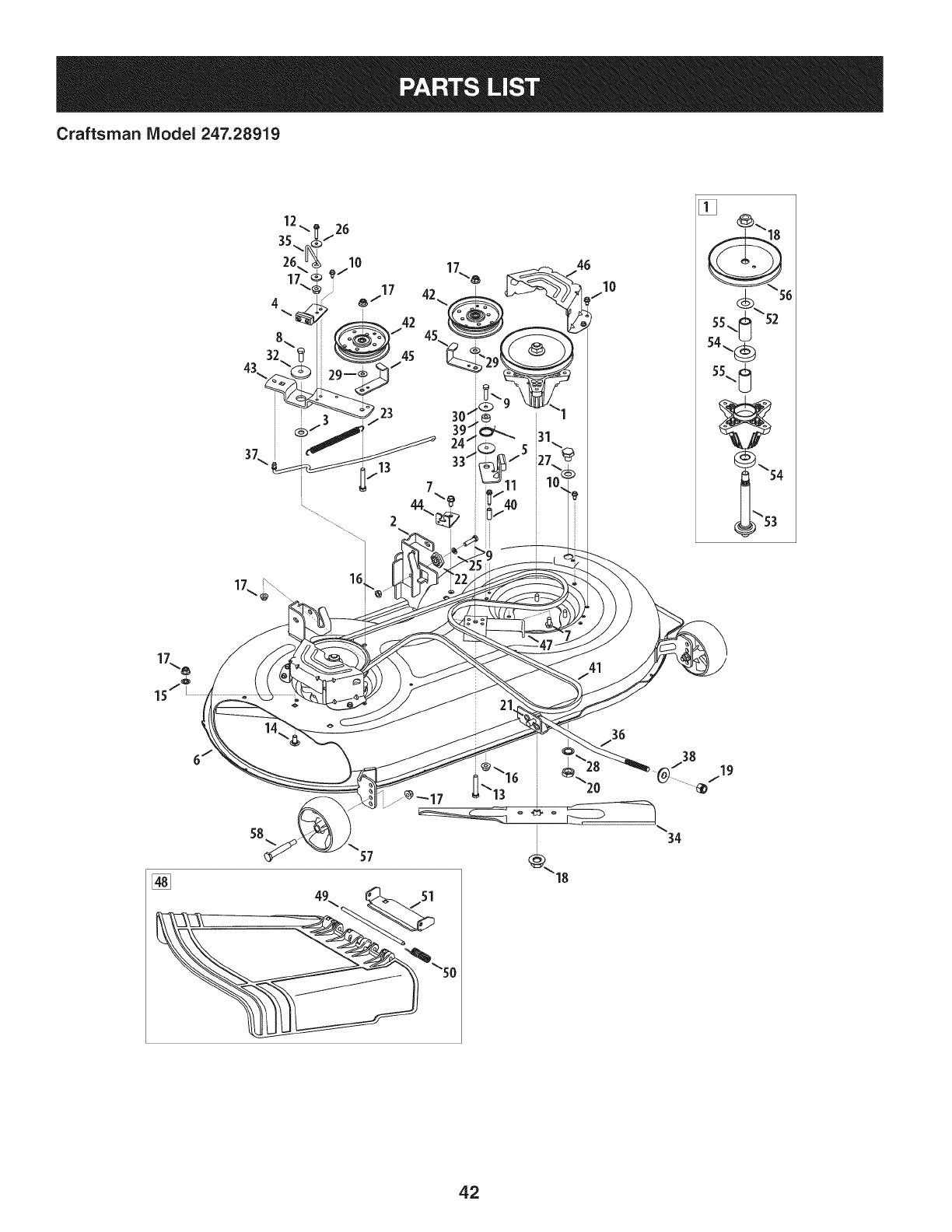
Craftsman IViodel 247.28919
46
10
41
57
42

Craftsman Model 247.28919
Ref, [
No,
1 918-04822A
2 683-0254B-0637
3 936-0344
4 983-04511
5 983-04525
6 983-04572-0637
7 710-04484
8 710-0514
9 710-0528
I0 710-0599
II 710-0778
12 710-0809
13 710-3144
14 710-3178
15 712-0229
16 712-04063
17 712-04065
18 712-0417A
19 712-04243
20 912-0641
21 714-04043
22 917-04074
23 932-0384
24 732-04727
25 936-0119
26 936-0176
27 736-0187
28 736-0225
29 736-0262
Part No, Description
Spindle Pulley Assembly
Deck Hanger Bracket Assembly
Wash, Flat, .385 x 1.0 x .030
Brake Assembly
Brake Assembly
Deck
Screw, 5/16-18 x .750
Screw, 3/8-16 x 1.00
Hex Screw, 5/16-18 x 1.25
Screw, 1/4-20 x .500
Screw, 1/4-20 x 1.50
Screw, 1/4-20 x 1.250
Hex Head Screw, 3/8-16
Carriage Bolt, 3/8-16 x .75
Push Nut, 3/8
Flangelock Nut, 5/16-18
Flangelock Nut, 3/8-16
Flange Nut, 5/8-18
Flangelock Nut, 1/2-13
Hex Nut, M16 - 1.5
Cotter Pin, Bow-Tie
Deck Adjuster Gear
Extension Spring, .62 x 6.12
Torsion Spring, 1.0 x 1.17
Lock Washer, 5/16
Flat Washer, .265 x 9.38 x .120
Flat Washer, .64 x 1.24 x .06
Flat Washer, .5/8 Int. Tth.
Flat Washer, .385 x .870 x .092
Ref, [
No,
30 736-0362
31 738-04146
32 738-04162A
33 738-04166
34 942-04308
35 747-04530
36 747-04944B
37 747-05105
38 748-04069
39 750-0258
40 750-0566A
41 954-04060B
42 756-04129B
43 783-05946
44 783-06243-0637
45 783-06368-0637
46 783-06424A-0637
47 783-06643-0637
48 631-04460
49 711-04847A
50 732-04372
51 783-06074A
52 936-0351
53 738-1186A
54 941-0919
55 750-04936
56 956-1227
57 734-04155
58 938-3056
Part No, Description
Flat Washer, .330 x 1.25 x .06
Bolt Plug, M16x 1.5
Shoulder Spacer, .8840 x .190
Shoulder Spacer, .5000 x .1475
Cutting Blade, 21.23": 2 in 1
Belt Keeper Rod
Deck Lift Rod
Brake Control Rod
Deck Lift Pivot Cup
Spacer
Spacer
V-Type Belt, 96.5
Idler Pulley, 4.25 Diameter
Idler Pivot Bracket
Deck Cable Engagement Bracket
Belt Pulley Guard
Deck Belt Cover
Deck Support Bracket
Chute Deflector Assembly
Hinge Pin
Torsion Spring, .44 x 2.0
Chute Bracket
Flat Washer, .760 x 1.50
Spindle Shaft
Ball Bearing, .787 x 1.85 x .551
Spacer, .792 x 1.060 x 1.860
Spindle Pulley
Deck Wheel, 5" Dia. Ball
Shoulder Bolt, 3/8-16
43
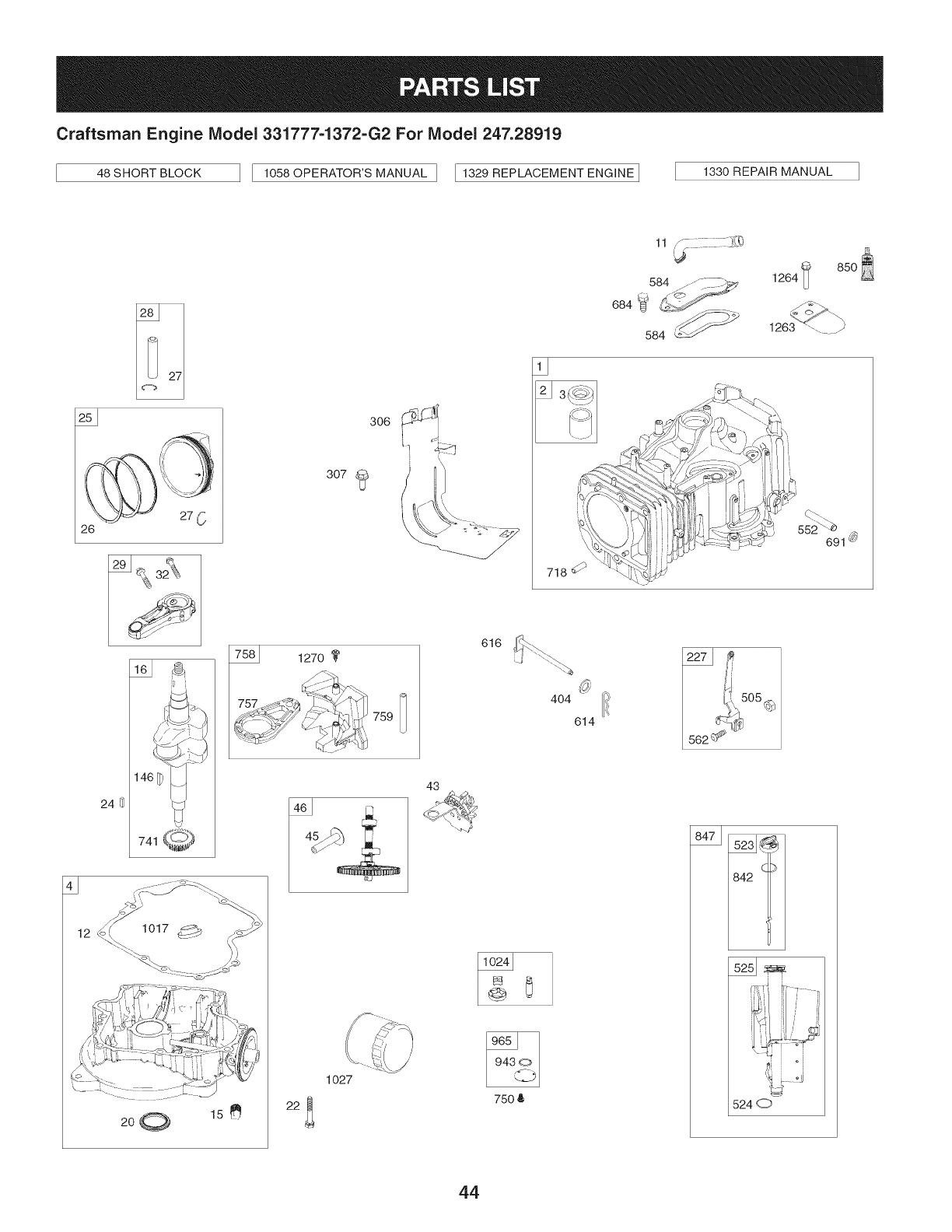
Craftsman Engine Model 331777-1372-G2 For Model 247.28919
46sHORTBLOCK ] I 1056OPERATORSMANU_LI [1329_EPL_OEMENTE_G,_EI 1330_E_,__UAL
200 15e
306
307
1270
759
1o27
22_
43
616
750 8
..... ,_
11 /£_
564 ......:C_
684 U _-'_J_" ..
584
85O
1264
718 _ '4_
552_ -_ _.
691 _9_
4O4
614
842
5240
44
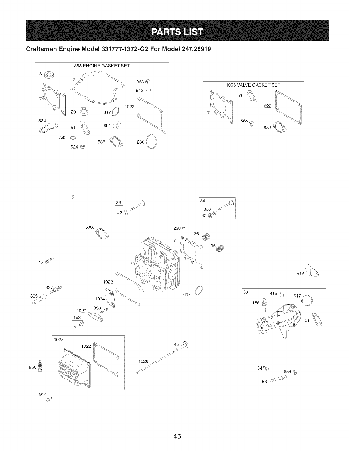
Craftsman Engine Model 331777=1372=G2 For Model 247.28919
,,._ y
358 ENGINE GASKET SET
12
584 , id_,_
842 0 888
524 @
1022
1266ii_i
1095 VALVE GASKET SET
51
1022
868@
13J
883
1022
238 O
617
85O
914
1023
' ii _--<
i \_ ii
51A_
415 _ 617
186
51
54% 654
45
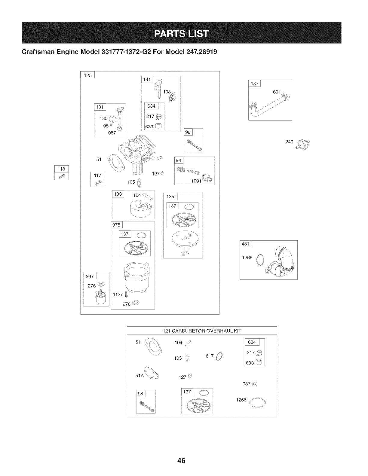
Craftsman Engine IViodel 331777-1372-G2 For Model 247.28919
987
51
87 601
24O
947
276 _
, ',.-)
1127
276 q_:
51
121 CARBURETOR OVERHAUL KiT
104 _105 _ 617 O
987 (_
1266 S_::;_'_,
..........f
46
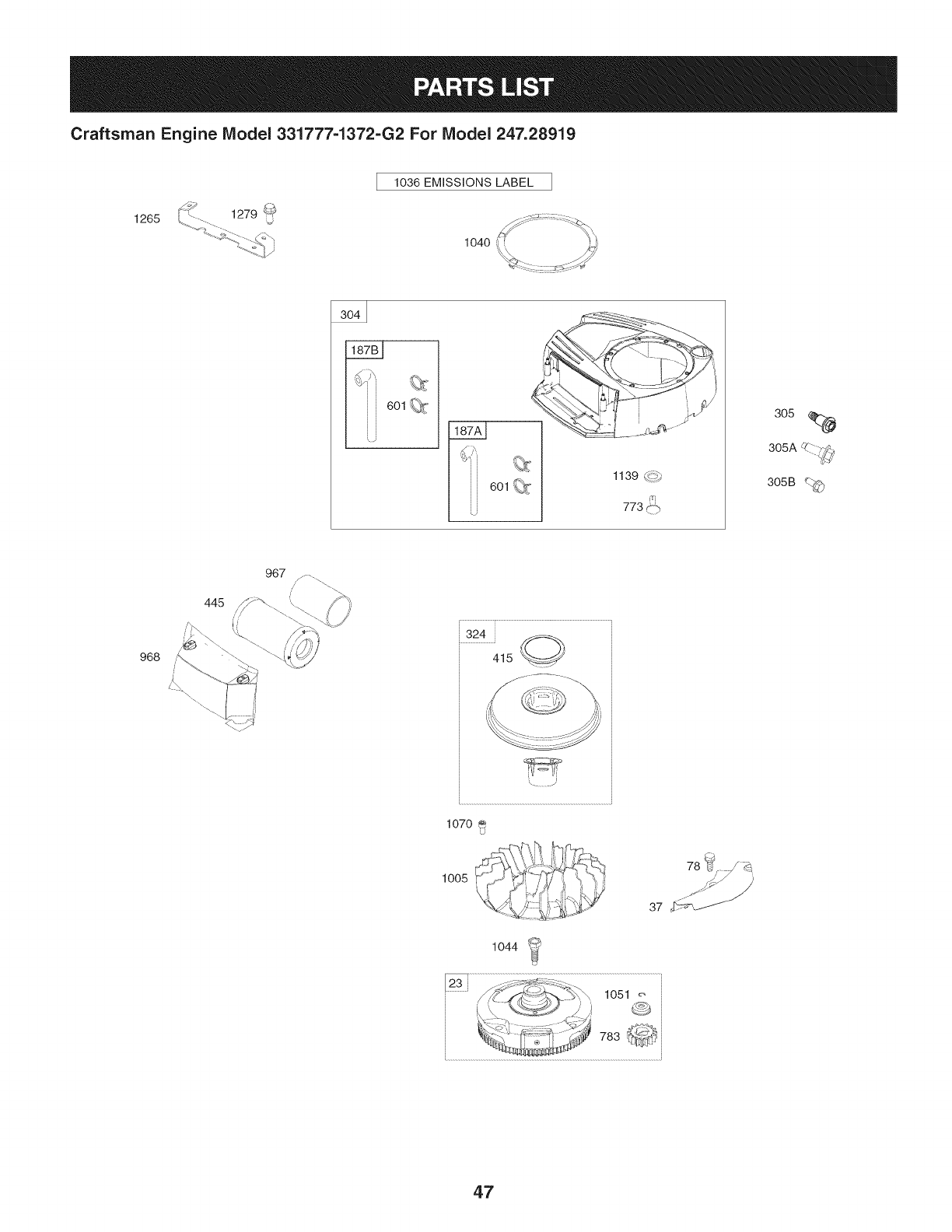
Craftsman Engine Model 331777=1372=G2 For Model 247.28919
1036 EMiSSiONS LABEL
1265
1040
6o1_:-
6o1_T 1139 _!p_
773P'"-
305
305A _'-_-_-
305B C_<_
968
967
324
415 Q@
1070
1005 78 b_; _ _._,
1044 _
...................J 1051 _
• :_! _'_i.=';_;'i_ 783 _ _,_
47
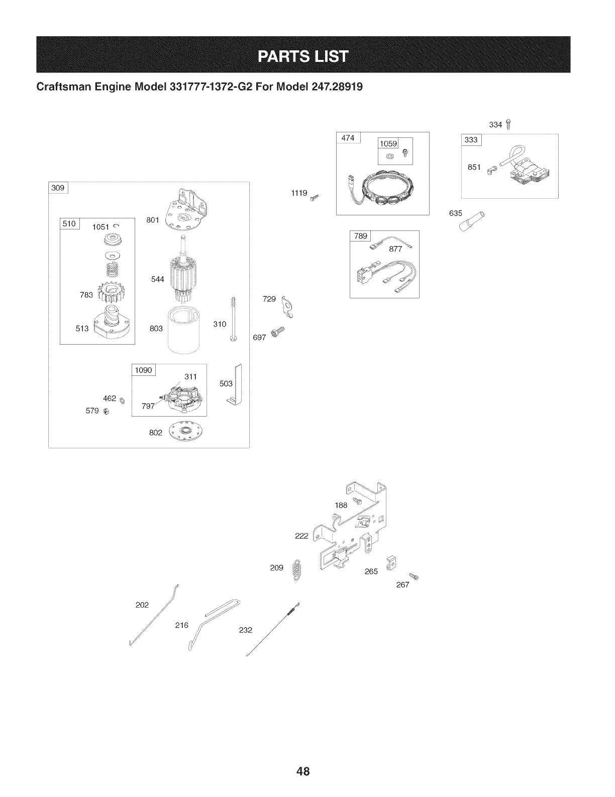
Craftsman Engine IViodel 331777-1372-G2 For IViodel 247.28919
310
729
1119
474i
334
851
209
48
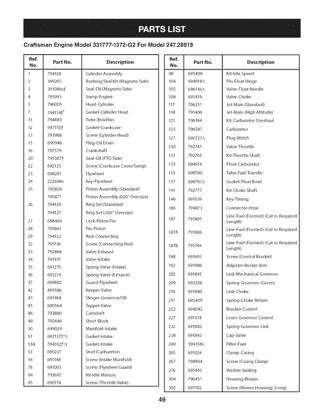
Craftsman Engine Model 331777-1372=G2 For Model 247.28919
Ref, ]
No,
1 794128
2399265
3 391086si
4 795993
5 796005
7 7941141"
II 794683
12 6971101
13 793988
15 690946
16 797579
20 7953871
22 692125
23 698281
24 222698s
25 795858
795877
26 794126
794127
27 698469
28 795861
29 794122
32 791118
33 792868
34 791935
35 691279
36 691279
37 699882
42 499586
43 691968
45 690564
46 793880
48 795446
50 699029
51 6921371_A
51A 7943121"A
53 690227
54 691148
78 691003
94 793610
95 690718
Part No, Description
Cylinder Assembly
Bushing/Seal Kit (Magneto Side)
Seal-Oil (Magneto Side)
Sump-Engine
Head-Cylinder
Gasket-Cylinder Head
Tu be- Breather
Gasket-Crankcase
Screw (Cylinder Head)
Plug-Oil Drain
Crankshaft
Seal-Oil (PTO Side)
Screw (Crankcase Cover/Sump)
Flywheel
Key-Flywheel
Piston Assembly (Standard)
Piston Assembly (020" Oversize)
Ring Set (Standard)
Ring Set (.020" Oversize)
Lock-Piston Pin
Pin-Piston
Rod-Connecting
Screw (Connecting Rod)
Valve-Exhaust
Valve-Intake
Spring-Valve (Intake)
Spring-Valve (Exhaust)
Guard-Flywheel
Keeper-Valve
Slinger-Governor/Oil
Tappet-Va Ive
Camshaft
Short Block
Manifold-Intake
Gasket-Intake
Gasket-Intake
Stud (Carburetor)
Screw (Intake Manifold)
Screw (Flywheel Guard)
Kit-Idle Mixture
Screw (Throttle Valve)
Ref, Part No,
NO,
98 695408
104 694918A
105 696136A
108 695419
117 796251
118 791406
121 796184
125 796587
127 690727A
130 792747
131 792765
133 694914
135 698780
137 698781A
141 792777
146 691639
186 794873
187 791805
187A 791806
187B 791744
188 691693
192 691986
202 691841
209 692208
216 691840
217 695409
222 694042
227 691374
232 691842
238 691843
240 394358s
265 691024
267 794904
276 695410
304 796451
305 697102
Description
Kit-Idle Speed
Pin-Float Hinge
Valve-Float Needle
Valve-Choke
Jet-Main (Standard)
Jet-Main (High Altitude)
Kit-Carburetor Overhaul
Carburetor
Plug-Welch
VaIve-Th rottle
Kit-Throttle Shaft
Float-Ca rburetor
Tube-Fuel Transfer
Gasket-Float Bowl
Kit-Choke Shaft
Key-Timing
Connector-Hose
Line-Fuel (Formed) (Cut to Required
Length)
Line-Fuel (Formed) (Cut to Required
Length)
Line-Fuel (Formed) (Cut to Required
Length)
Screw (Control Bracket)
Adjuster-Rocker Arm
Link-Mechanical Governor
Spring-Governor (Green)
Link-Choke
Spring-Choke Return
Bracket-Control
Lever-Governor Control
Spring-Governor Link
Cap-Valve
Filter-Fuel
Clamp-Casing
Screw (Casing Clamp)
Washer-Sealing
Housing-Blower
Screw (Blower Housing) (Long)
49
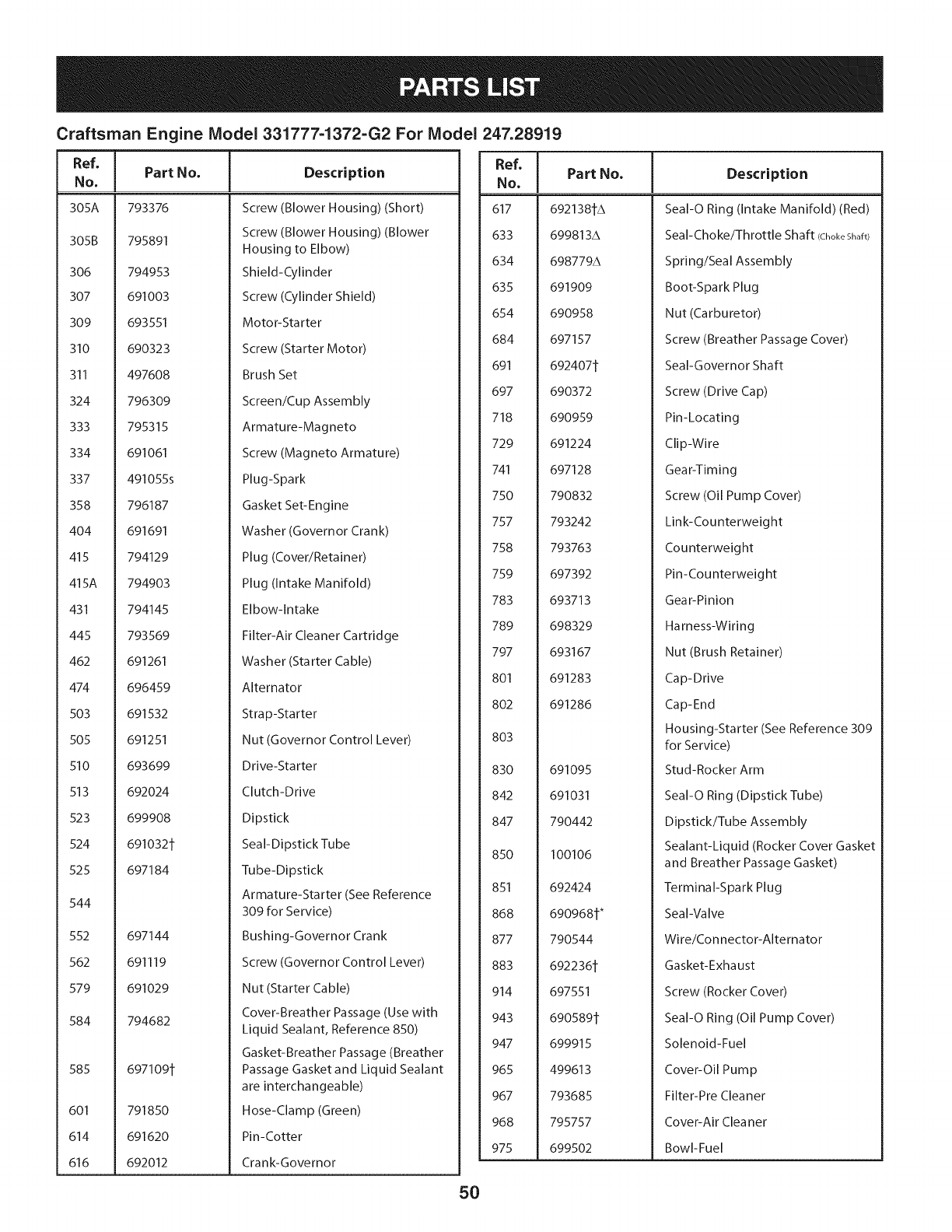
Craftsman Engine Model 331777-1372=G2 For Model 247.28919
Ref,
No,
305A 793376
305B 795891
306 794953
307 691003
309 693551
310 690323
311 497608
324 796309
333 795315
334 691061
337 491055s
358 796187
404 691691
415 794129
415A 794903
431 794145
445 793569
462 691261
474 696459
503 691532
505 691251
510 693699
513 692024
523 699908
524 691032t
525 697184
544
552 697144
562 691119
579 691029
584 794682
585 697109t
601 791850
614 691620
616 692012
Part No, Description
Screw (Blower Housing) (Short)
Screw (Blower Housing) (Blower
Housing to Elbow)
Shield-Cylinder
Screw (Cylinder Shield)
Motor-Starter
Screw (Starter Motor)
Brush Set
Screen/Cup Assembly
Armature-Magneto
Screw (Magneto Armature)
Plug-Spark
Gasket Set-Engine
Washer (Governor Crank)
Plug (Cover/Retainer)
Plug (Intake Manifold)
Elbow-Intake
Filter-Air Cleaner Cartridge
Washer (Starter Cable)
Alternator
Strap-Starter
Nut (Governor Control Lever)
Drive-Starter
Clutch-Drive
Dipstick
Seal-Dipstick Tube
Tube-Dipstick
Armature-Starter (See Reference
309 for Service)
Bushing-Governor Crank
Screw (Governor Control Lever)
Nut (Starter Cable)
Cover-Breather Passage (Use with
Liquid Sealant, Reference 850)
Gasket-Breather Passage (Breather
Passage Gasket and Liquid Sealant
are interchangeable)
Hose-Clamp (Green)
Pin-Cotter
Crank-Governor
Ref, [
No,
617
633
634
635
654
684
691
697
718
729
741
750
757
758
759
783
789
797
801
8o2
803
830
842
847
85O
851
868
877
883
914
943
947
965
967
968
975
Part No, Description
692138_A
699813A
698779A
691909
690958
697157
692407_
690372
690959
691224
697128
790832
793242
793763
697392
693713
698329
693167
691283
691286
691095
691031
790442
I00106
692424
690968_*
790544
692236_
697551
690589t
699915
499613
793685
795757
699502
SeaI-O Ring (Intake Manifold) (Red)
Seal-Choke/Throttle Shaft (ChokeShaft)
Spring/Seal Assembly
Boot-Spark Plug
Nut (Carburetor)
Screw (Breather Passage Cover)
Seal-Governor Shaft
Screw (Drive Cap)
Pin-Locating
Clip-Wire
Gear-Timing
Screw (Oil Pump Cover)
Link-Counterweight
Counterweight
Pin-Counterweight
Gear-Pinion
Harness-Wiring
Nut (Brush Retainer)
Cap-Drive
Cap-End
Housing-Starter (See Reference 309
for Service)
Stud-Rocker Arm
SeaI-O Ring (Dipstick Tube)
Dipstick/Tube Assembly
Sealant-Liquid (Rocker Cover Gasket
and Breather Passage Gasket)
Terminal-Spark Plug
Seal-Valve
Wire/Connector-Alternator
Gasket-Exhaust
Screw (Rocker Cover)
SeaI-O Ring (Oil Pump Cover)
Solenoid-Fuel
Cover-Oil Pump
Filter-Pre Cleaner
Cover-Air Cleaner
Bowl-Fuel
50
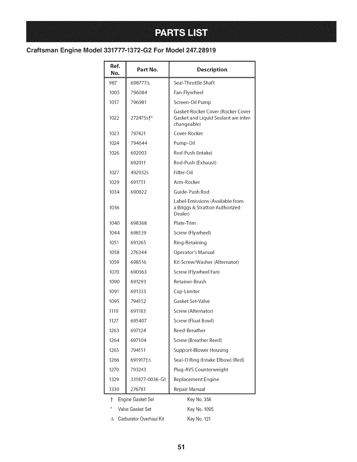
Craftsman Engine Model 331777-1372-G2 For Model 247.28919
Ref,
No,
987
1005
1017
Part No. Description
698777A
796084
796981
1022 272475st _
1023 797421
1024 794644
1026 692003
692011
1027 492932s
1029 691751
1034 690822
1036
1040 698368
1044 698139
1051 691265
1058 276344
I059 698516
I070 690363
I090 691293
1091 691333
I095 794152
Ill9 691183
I127 695407
1263 697124
1264 697104
1265 794151
1266 691917tA
1270 793243
1329 331877-0036-GI
1330 276781
t Engine GasketSet
* Valve Gasket Set
A Carburetor OverhauI Kit
Seal-Throttle Shaft
Fan-Flywheel
Screen-Oil Pump
Gasket-Rocker Cover (Rocker Cover
Gasket and Liquid Sealant are inter-
changeable)
Cover-Rocker
Pump-Oil
Rod-Push (Intake)
Rod-Push (Exhaust)
Filter-Oil
Arm-Rocker
Guide-Push Rod
Label-Emissions (Available from
a Briggs & Stratton Authorized
Dealer)
Plate-Trim
Screw (Flywheel)
Ring-Retaining
Operator's Manual
Kit-Screw/Washer (Alternator)
Screw (Flywheel Fan)
Retainer-Brush
Cap-Limiter
Gasket Set-Valve
Screw (Alternator)
Screw (Float Bowl)
Reed-Breather
Screw (Breather Reed)
Support-Blower Housing
Seal-O Ring (Intake Elbow) (Red)
Plug-AVS Counterweight
Replacement Engine
Repair Manual
Key No. 358
Key No. 1095
Key No. 121
51

This page intentionally left blank. Use this page to make any notes regarding your tractor.
52

This page intentionally left blank. Use this page to make any notes regarding your tractor.
53
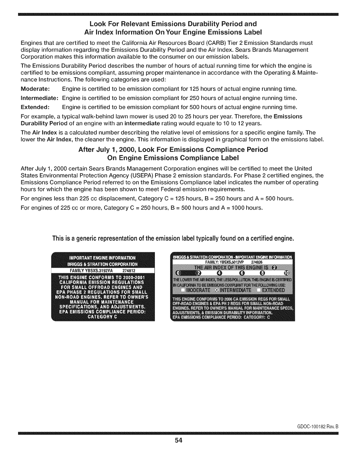
Look For Relevant Emissions Durability Period and
Air index information On Your Engine Emissions Label
Engines that are certified to meet the California Air Resources Board (CARB) Tier 2 Emission Standards must
display information regarding the Emissions Durability Period and the Air Index. Sears Brands Management
Corporation makes this information available to the consumer on our emission labels.
The Emissions Durability Period describes the number of hours of actual running time for which the engine is
certified to be emissions compliant, assuming proper maintenance in accordance with the Operating & Mainte-
nance Instructions. The following categories are used:
Moderate: Engine is certified to be emission compliant for 125 hours of actual engine running time.
Intermediate: Engine is certified to be emission compliant for 250 hours of actual engine running time.
Extended: Engine is certified to be emission compliant for 500 hours of actual engine running time.
For example, a typical walk-behind lawn mower is used 20 to 25 hours per year. Therefore, the Emissions
Durability Period of an engine with an intermediate rating would equate to 10 to 12 years.
The Air index is a calculated number describing the relative level of emissions for a specific engine family. The
lower the Air Index, the cleaner the engine. This information is displayed in graphical form on the emissions label.
After July 1,2000, Look For Emissions Compliance Period
On Engine Emissions Compliance Label
After July 1, 2000 certain Sears Brands Management Corporation engines will be certified to meet the United
States Environmental Protection Agency (USEPA) Phase 2 emission standards. For Phase 2 certified engines, the
Emissions Compliance Period referred to on the Emissions Compliance label indicates the number of operating
hours for which the engine has been shown to meet Federal emission requirements.
For engines less than 225 cc displacement, Category C = 125 hours, B = 250 hours and A = 500 hours.
For engines of 225 cc or more, Category C = 250 hours, B = 500 hours and A = 1000 hours.
This is ageneric representation of the emission label typically found on a certified engine.
FAMILYYBSXS.3192VA 274812
GDOC-100182Rev.B
54
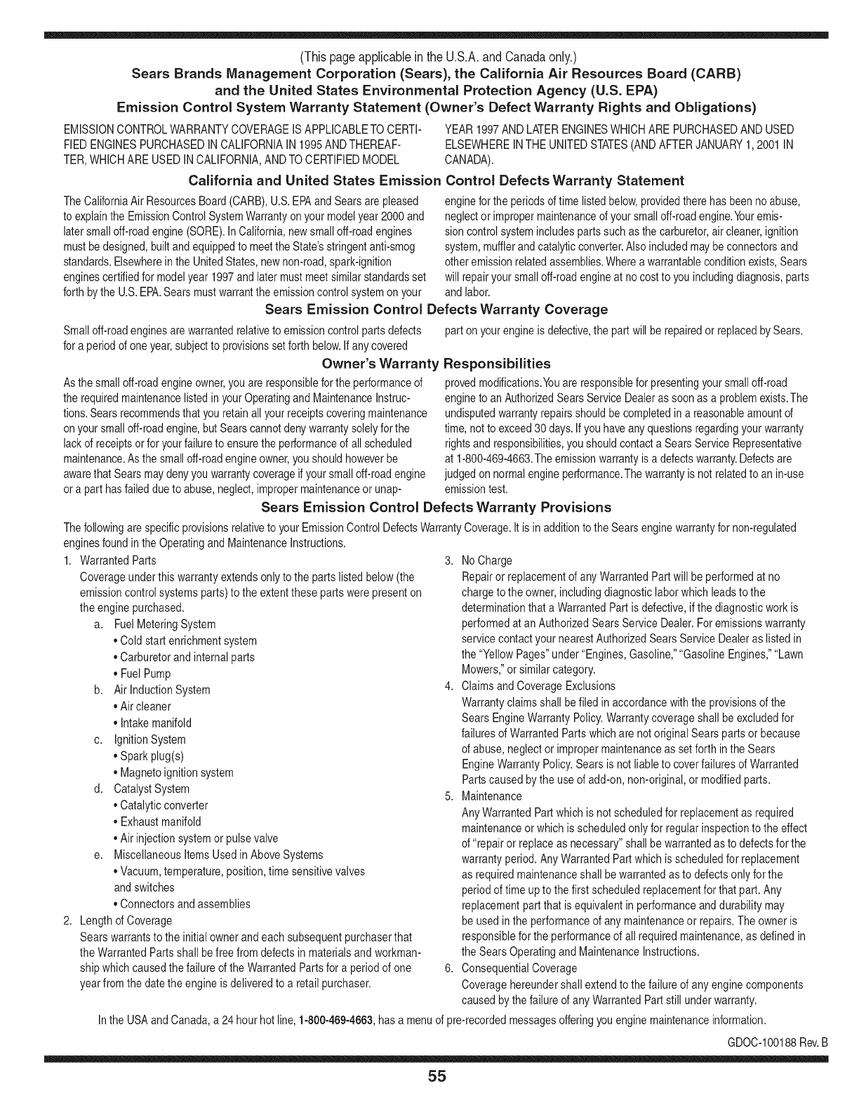
(Thispageapplicableinthe U.S.A.and Canadaonly.)
Sears Brands Management Corporation (Sears), the California Air Resources Board (CARD)
and the United States Environmental Protection Agency (U.S. EPA)
Emission Control System Warranty Statement (Owner's Defect Warranty Rights and Obligations)
EMISSIONCONTROLWARRANTYCOVERAGEISAPPLICABLETOCERTI-
FIEDENGINESPURCHASEDINCALIFORNIAIN1995ANDTHEREAF-
TER,WHICHARE USEDINCALIFORNIA,ANDTOCERTIFIEDMODEL
California and United States Emission
The CaliforniaAir ResourcesBoard(CARD),U.S.EPAand Searsare pleased
to explainthe EmissionControlSystemWarrantyon your modelyear2000and
latersmalloff-roadengine(SORE).InCalifornia,newsmall off-roadengines
mustbe designed,builtand equippedto meettheState'sstringentanti-smog
standards.Elsewherein theUnitedStates,newnon-road,spark-ignition
enginescertifiedfor modelyear 1997and latermustmeetsimilarstandardsset
forthbythe U.S.EPA.Searsmustwarranttheemissioncontrolsystemonyour
YEAR1997ANDLATERENGINESWHICHARE PURCHASEDAND USED
ELSEWHEREINTHEUNITEDSTATES(ANDAFTERJANUARY1,2001 IN
CANADA).
Control Defects Warranty Statement
enginefor theperiodsoftime listedbelow,providedtherehas beennoabuse,
neglector impropermaintenanceof your smalloff-roadengine.Youremis-
sion controlsystemincludespartssuch as thecarburetor,air cleaner,ignition
system,mufflerand catalyticconverter.Also includedmaybeconnectorsand
otheremissionrelatedassemblies.Wherea warrantableconditionexists,Sears
will repairyour smalloff-roadengineat no costto you includingdiagnosis,parts
and labor.
Sears Emission Control Defects Warranty Coverage
Smalloff-roadenginesarewarrantedrelativeto emissioncontrolpartsdefects
fora periodof one year,subjectto provisionsset forthbelow.Ifanycovered
Owner's Warranty
Asthe smalloff-roadengineowner,youare responsiblefor theperformanceof
therequiredmaintenancelistedin yourOperatingand MaintenanceInstruc-
tions.Searsrecommendsthatyouretainallyourreceiptscoveringmaintenance
onyoursmalloff-roadengine,butSearscannotdenywarrantysolelyfor the
lackof receiptsorfor yourfailureto ensuretheperformanceof all scheduled
maintenance.As the smalloff-roadengineowner,youshouldhoweverbe
awarethat Searsmaydenyyouwarrantycoverageifyour smalloff-roadengine
ora part hasfaileddueto abuse,neglect,impropermaintenanceor unap-
parton yourengineis defective,the partwillbe repairedorreplacedbySears.
Responsibilities
provedmodifications.Youare responsiblefor presentingyour smalloff-road
engineto anAuthorizedSearsServiceDealeras soonas a problemexists.The
undisputedwarrantyrepairsshouldbecompletedina reasonableamountof
time,notto exceed30 days.Ifyou haveany questionsregardingyourwarranty
rightsand responsibilities,you shouldcontacta SearsService Representative
at 1-800-469-4663.The emissionwarrantyisa defectswarranty.Defectsare
judgedon normalengineperformance.Thewarrantyis notrelatedto an in-use
emissiontest.
Sears Emission Control Defects Warranty Provisions
ThefollowingarespecificprovisionsrelativetoyourEmissionControlDefectsWarrantyCoverage.ItisinadditiontotheSearsenginewarrantyfornon-regulated
enginesfoundin theOperatingand MaintenanceInstructions.
1. WarrantedParts
Coverageunderthis warrantyextendsonly to the parts listedbelow (the
emissioncontrolsystemsparts)to the extentthese partswere presenton
the enginepurchased.
a. FuelMeteringSystem
•Cold start enrichmentsystem
•Carburetorand internalparts
•FuelPump
b. AirlnductionSystem
•Aircleaner
•Intakemanifold
c. IgnitionSystem
•Sparkplug(s)
•Magnetoignitionsystem
d. CatalystSystem
•Catalyticconverter
•Exhaustmanifold
•Air injectionsystemor pulsevalve
e. MiscellaneousItemsUsedin AboveSystems
•Vacuum,temperature,position,timesensitivevalves
andswitches
•Connectorsandassemblies
2. Lengthof Coverage
Searswarrantsto the initialownerand eachsubsequentpurchaserthat
the WarrantedParts shallbefree fromdefects in materialsandworkman-
shipwhich causedthefailure of the WarrantedPartsfor a periodof one
yearfromthe datethe engineis deliveredto a retailpurchaser.
3. NoCharge
Repairor replacementof anyWarrantedPartwill be performedat no
chargeto the owner,includingdiagnosticlaborwhichleadsto the
determinationthata WarrantedPartis defective,ifthe diagnosticwork is
performedat an AuthorizedSears ServiceDealer.Foremissionswarranty
servicecontact yournearestAuthorizedSears ServiceDealeras listed in
the "YellowPages"under"Engines,Gasoline,""GasolineEngines,""Lawn
Mowers,"orsimilarcategory.
4. Claimsand CoverageExclusions
Warrantyclaimsshall be filed in accordancewiththe provisionsof the
SearsEngineWarrantyPolicy.Warrantycoverageshall be excludedfor
failuresof WarrantedPartswhichare notoriginal Searspartsor because
of abuse,neglector impropermaintenanceas setforth inthe Sears
EngineWarrantyPolicy.Sears isnotliableto coverfailuresof Warranted
Partscausedby theuse of add-on,non-original,or modifiedparts.
5. Maintenance
Any WarrantedPart whichis notscheduledfor replacementas required
maintenanceor whichis scheduledonly for regularinspectionto the effect
of "repairor replaceas necessary"shallbe warrantedasto defectsfor the
warrantyperiod.AnyWarrantedPartwhich is scheduledfor replacement
as requiredmaintenanceshallbe warrantedasto defectsonly forthe
periodof time up to the first scheduledreplacementfor that part. Any
replacementpart that isequivalentin performanceand durabilitymay
be usedin the performanceof any maintenanceor repairs.Theowneris
responsibleforthe performanceof allrequiredmaintenance,as definedin
the SearsOperatingand MaintenanceInstructions.
6. ConsequentialCoverage
Coveragehereundershallextendto the failureof any enginecomponents
caused bythe failureof anyWarrantedPartstill underwarranty.
Inthe USAandCanada,a 24 hourhotline, 1-800-469-4663,hasa menu of pre-recordedmessagesofferingyou enginemaintenanceinformation.
GD0C-100188Rev.B
55
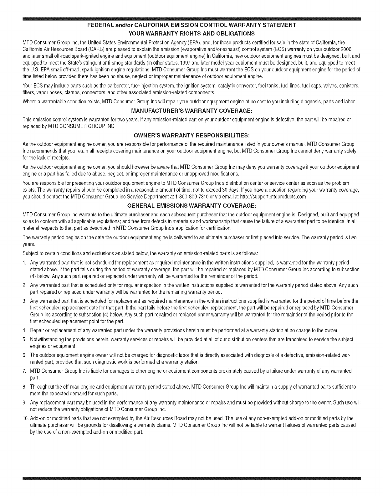
FEDERAL and/or CALIFORNIA EMISSION CONTROL WARRANTY STATEMENT
YOUR WARRANTY RIGHTS AND OBLIGATIONS
MTDConsumerGroupInc,the UnitedStatesEnvironmentalProtectionAgency (EPA),and, forthose productscertifiedfor sale in the stateof California,the
CaliforniaAir ResourcesBoard(CARB)are pleasedto explainthe emission(evaporativeand/or exhaust)controlsystem(ECS) warrantyonyouroutdoor2006
andlater smalloff-roadspark-ignitedengineandequipment(outdoorequipmentengine)In California,new outdoorequipmentenginesmustbe designed,built and
equippedto meetthe State'sstringentanti-smogstandards(inotherstates, 1997andlater modelyear equipmentmustbedesigned,built,and equippedto meet
theU.S. EPAsmalloff-road,sparkignitionengineregulations.MTDConsumerGroupInc mustwarrantthe ECSon your outdoorequipmentenginefor the periodof
timelisted belowprovidedtherehas been noabuse, neglector impropermaintenanceof outdoorequipmentengine.
YourECSmayincludeparts suchas thecarburetor,fuel-injectionsystem,the ignitionsystem,catalyticconverter,fuel tanks,fuel lines,fuelcaps,valves,canisters,
filters,vaporhoses,clamps,connectors,andotherassociatedemission-relatedcomponents.
Wherea warrantableconditionexists, MTDConsumerGroupIncwill repairyouroutdoorequipmentengineat no cost to youincludingdiagnosis,parts and labor.
MAN UFACTURER'S WARRANTY COVERAGE:
Thisemissioncontrolsystemiswarrantedfor two years. If anyemission-relatedpartonyour outdoorequipmentengineis defective,the part will be repairedor
replacedby MTDCONSUMERGROUPINC.
OWNER'S WARRANTY RESPONSIBILITIES:
Asthe outdoorequipmentengineowner,you are responsiblefor performanceof the requiredmaintenancelisted inyour owner'smanual.MTDConsumerGroup
Inc recommendsthat you retainallreceiptscoveringmaintenanceon youroutdoorequipmentengine,butMTDConsumerGroupInc cannotdeny warrantysolely
forthe lackof receipts.
Asthe outdoorequipmentengineowner,you shouldhoweverbe awarethat MTDConsumerGroupInc may denyyouwarrantycoverageifyour outdoorequipment
engineor a part hasfaileddue toabuse,neglect,or impropermaintenanceor unapprovedmodifications.
Youare responsiblefor presentingyouroutdoorequipmentengineto MTDConsumerGroupInc'sdistributioncenterorservicecenteras soon asthe problem
exists.Thewarrantyrepairsshouldbecompletedin a reasonableamountof time, notto exceed30 days.If youhavea questionregardingyour warrantycoverage,
you shouldcontactthe MTDConsumerGroupIncService Departmentat 1-800-800-7310orvia emailat http://support.mtdproducts.com
GENERAL EMISSIONS WARRANTY COVERAGE:
MTDConsumerGroupIncwarrantsto the ultimatepurchaserand eachsubsequentpurchaserthat theoutdoorequipmentengineis: Designed,built and equipped
so asto conformwithall applicableregulations;and freefromdefects in materialsand workmanshipthatcausethe failureof a warrantedpart to be identicalin all
materialrespectsto that part as describedin MTDConsumerGroup Inc'sapplicationfor certification.
The warrantyperiodbeginsonthedate theoutdoorequipmentengineis deliveredto an ultimatepurchaserorfirst placedintoservice.The warrantyperiodis two
years.
Subjectto certainconditionsand exclusionsasstated below,the warrantyonemission-relatedparts is asfollows:
1. Anywarrantedpart that is notscheduledfor replacementas requiredmaintenancein thewritten instructionssupplied,is warrantedforthe warrantyperiod
statedabove. Ifthe part fails duringthe periodof warrantycoverage,thepart will be repairedor replacedbyMTDConsumerGroupInc accordingto subsection
(4)below.Anysuchpart repairedor replacedunderwarrantywillbe warrantedfor the remainderof the period.
2. Anywarrantedpart that isscheduledonly for regularinspectionin the writteninstructionssuppliediswarrantedforthe warrantyperiodstatedabove.Any such
partrepairedor replacedunderwarrantywill bewarrantedforthe remainingwarrantyperiod.
3. Anywarrantedpart that isscheduledfor replacementas requiredmaintenancein thewritten instructionssuppliedis warrantedfor the periodof timebeforethe
firstscheduledreplacementdatefor that part.If the partfails beforethefirst scheduledreplacement,the partwill berepairedor replacedby MTDConsumer
GroupInc accordingto subsection(4) below.Anysuch partrepairedor replacedunderwarrantywill be warrantedfor the remainderof the periodpriorto the
firstscheduledreplacementpointfor the part.
4. Repairor replacementof any warrantedpart underthe warrantyprovisionshereinmustbe performedat a warrantystationat no chargeto the owner.
5. Notwithstandingthe provisionsherein,warrantyservicesor repairswill be providedat all of our distributioncentersthatare franchisedto servicethe subject
enginesor equipment.
6. Theoutdoorequipmentengineownerwill notbe chargedfor diagnosticlaborthat isdirectlyassociatedwithdiagnosisof a defective,emission-relatedwar-
rantedpart, providedthat suchdiagnosticwork is performedat a warrantystation.
7. MTDConsumerGroupInc is liablefor damagesto otherengineor equipmentcomponentsproximatelycausedby a failure underwarrantyof any warranted
part.
8. Throughoutthe off-roadengineand equipmentwarrantyperiodstatedabove,MTDConsumerGroupInc will maintaina supplyof warrantedparts sufficientto
meetthe expecteddemandfor suchparts.
9. Anyreplacementpart maybe usedinthe performanceof anywarrantymaintenanceor repairsand mustbeprovidedwithoutchargeto the owner.Suchusewill
notreducethe warrantyobligationsof MTDConsumerGroupInc.
10.Add-onor modifiedpartsthat are notexemptedbythe Air ResourcesBoardmaynot beused.The useof any non-exemptedadd-onor modifiedpartsby the
ultimatepurchaserwill be groundsfor disallowinga warrantyclaims. MTDConsumerGroup Incwill notbe liableto warrantfailuresof warrantedparts caused
bythe useof a non-exemptedadd-onor modifiedpart.
WARRANTED PARTS:
The repairor replacementof any warrantedpart otherwiseeligiblefor warrantycoveragemaybe excludedfromsuch warrantycoverageif MTDConsumerGroup
Inc demonstratesthatthe outdoor equipmentenginehas beenabused,neglected,orimproperlymaintained,and thatsuch abuse,neglect,or impropermainte-
nancewasthe direct causeof the needfor repairor replacementof the part.Thatnotwithstanding,anyadjustmentof a componentthat hasa factoryinstalled,
andproperlyoperating,adjustmentlimitingdeviceis still eligible for warrantycoverage.Further,the coverageunderthis warrantyextendsonly to partsthat were
presentonthe off-roadengineand equipmentpurchased.
Thefollowing emissionwarrantypartsare covered(if applicable):
(1)FuelMeteringSystem
• Cold start enrichmentsystem(softchoke)
• Carburetorand internalparts(or fuel injectionsystem)
• Fuelpump
• Fueltank
(2)Air InductionSystem
• Aircleaner
• Intakemanifold
(3) IgnitionSystem
• Sparkplug(s)
• Magnetoignitionsystem
(4) ExhaustSystem
• Catalyticconverter
• SAI(Reed valve)
(5) MiscellaneousItemsUsedin AboveSystem
• Vacuum,temperature,position,timesensitivevalvesand switches
• Connectorsandassemblies
(6) EvaporativeControl
• Fuelhose
• Fuelhoseclamps
• Tetheredfuel cap
• Carboncanister
• Vapor lines
GDOC-100223Rev.A
Congratulationson makinga smartpurchase.YournewCraftsman@
productis designedandmanufacturedfor yearsof dependableopera-
tion.But likeall products,it mayrequirerepairfromtimeto time.That's
whenhavinga RepairProtectionAgreementcansaveyoumoneyand
aggravation.
Here'swhatthe RepairProtectionAgreement*includes:
* Expert service byour 10,000professionalrepairspecialists
oUnlimitedserviceand no chargefor partsand laboron all
coveredrepairs
o Product replacementupto $1500if yourcoveredproductcan't be
fixed
•Discountof 10%from regularprice of serviceand relatedinstalled
partsnotcoveredby theagreement;also,10%off regularpriceof
preventivemaintenancecheck
• Fast help by phone- we call it RapidResolution- phonesupport
froma Searsrepresentative.Thinkof usas a "talkingowner's
manual."
Onceyou purchasethe Agreement,a simplephonecall is all thatit
takesfor youto scheduleservice.Youcan call anytimedayor night,or
schedulea serviceappointmentonline.
The RepairProtectionAgreementis a risk-freepurchase.If youcancel
for any reasonduringthe productwarrantyperiod,wewill provideafull
refund.Or,a proratedrefundanytimeafterthe productwarrantyperiod
expires.Purchaseyour RepairProtectionAgreementtoday!
Somelimitationsand exclusionsapply. For pricesand additional
informationin the U.S.A.call 1-800-827-6655.
*Coverage inCanadavaries on some items.Forfull details call
Sears Canadaat 1-800-361-6665.
Sears Installation Service
ForSearsprofessionalinstallationof homeappliances,garagedoor
openers,waterheaters,andothermajorhomeitems,in the U.S.A.or
Canadacall 1-800-4-MY-HOME®.
58
Operaci6n segura Practicas .......... Paginas 60 Fuera de temporada de almacenamiento .. Page 85
Etiquetas De Seguridad ................ Page 66 Solucion de problemas ................ Page 86
Asamblea ........................... Page 67 Lista de piezas ..................... Paginas 30
Operacion de ...................... Paginas 69 Reparaci6n de Acuerdo de Proteccion .... Page 91
De Servicio y Mantenimiento de ....... Paginas 76 Servicio de nOmeros ............ atrasados Page
Artesano Garantia completa
Cuandose explotany mantienendeacuerdocon todaslasinstruccionessuministradas,encasodecualquierparte nofungiblesde esteequipo
demontarfalla debidoa undefectode materialo manode obradurantedosa_osa partirde la fechao la compra,Ilameal 1-800-659-5917para
organizarde formagratuitareparaci6nen el hogar.
Elmarcoy eleje delanteroser_reparadode formagratuitadurantecincoa_os a partirdela fechade comprasi est_defectuosoenel materialo
manode obra.
Todala coberturade la garantiaanteriorse aplicas61odurante90dias desdela fechadecomprasi el equipodeconducci6nes cadavez
utilizadocon finescomercialeso dealquiler.
Entodosloscasos,si la reparaci6nresultaimposible,el equipode montara caballoserAsustituidodeformagratuitaconel mismomodeloo uno
equivalente.
Labateriase sustituyede formagratuitadurante90 dfasa partirdela fechade comprasi estAdefectuosoenel materialo manode obra
(nuestroan_lisisdemuestraquenova a mantenerunacarga).
Estagarantias61ocubrelos defectosde materialy manodeobra. Searsnopagar_por:
•Loselementosconsumiblesquese desgastandurantesu usonormal,incluyendoperonolimitadoalas hojas,bujias,filtrosde aire,correas
y filtrosde aceite.
•Prestaci6nde serviciosde mantenimientonormal,cambiosdeaceite,o puestasa punto.
•Lasustituci6no reparaci6nde neumAticoscausadaporpinchazosde los objetosexternos,talescomoclavos,espinas,troncos,o devidrio.
•O reemplazode Ilantasde laruedao de reparaci6nque resultendeldesgastenormal,accidentes,u operaci6no mantenimientoinadec-
uado.
•Reparacionesnecesariasdebidoalabusodeloperador,incluyendoperonolimitadoada_oscausadosporobjetosde arrastrem_sall_de
lacapacidadde los equiposde equitaci6n,queafectanlosobjetosque sedoblanel marcoo el cigOe_al,o excesode velocidaddel motor.
•Reparacionesnecesariasdebidoa lanegligenciadeloperador,incluyendoperonolimitadoa, da_osel_ctricosy mec_nicoscausadospor
unalmacenamientoinadecuado,faltade utilizaci6nde lacategoriaapropiaday lacantidaddeaceitedelmotor,faltade mantenimientodela
cubiertaclarade los residuosinflamables,o faltade mantenimientode lacabalgataequipode acuerdoalas instruccionescontenidasenel
manualdeloperador.
•Del motor(sistemade combustible),lalimpiezao reparacionescausadasporcombustibledeterminadadecontaminaci6no oxidado
(rancio).Engeneral,el combustibledebe serutilizadadentrode 30dias de sufechadecompra.
•Eldeterioroy desgastenormaldelos acabadosexteriores,o la sustituci6netiquetadelproducto.
•Estagarantiase aplicas61ocuandoesteproductose encuentradentrode los EstadosUnidos.
•Estagarantialeotorgaderechoslegalesespecificos,y ustedtambi_npuedetenerotrosderechosquevariandeestadoa estado.
•Eldeterioroy desgastenormaldelos acabadosexteriores,o la sustituci6netiquetadelproducto.
Estagarantiaseaplica s61ocuandoeste productose encuentradentrode los EstadosUnidos.
Estagarantialeotorgaderechoslegalesespecificos,y ustedtambi_npuedetenerotrosderechosque variandeestadoa estado.
Sears, Roebuck and Co. Hoffman Estates, IL 60179
BrutoHP: 20
Aceitedel motor: SAE30
Combustible: Gasolinasinplomo
Bujia: Champion®RC12YC
Motor: Briggs& StrattonIntek®
N_mero de modelo ..........................................................
N_mero de serie ..............................................................
Fechade compra .............................................................
Registrearribael nOmerodel modelo,el nOmerode seriey la fecha
de compra
©SearsBrands,LLC
59
Lapresenciade estesirnboloindicaque setratade instrucciones
irnportantesde seguridadquese debenrespetarparaevitar
ponerenpeligrosu seguridadpersonaly/o materialy lade otras
personas.Leay sigatodaslasinstruccionesdeestemanualantes
de poneren funcionarnientoestarn_.quina.Si no respetaestas
instruccionespodriaprovocarlesionespersonales.Cuandoveaeste
sirnbolo,ipresteatenci6na la advertencia!
PROPOSICION 65 DE CALIFORNIA
Elescapedel motorde esteproducto,algunosdesuscornponentes
y algunoscornponentesdelvehiculocontieneno liberansustancias
quirnicasqueelestadode Californiaconsideraque puedenproducir
c_.ncer,defectosde nacirnientouotrosproblernasreproductivos.
Losbornesdela bateriay losaccesoriosdines contienenplornoy
cornpuestosde plorno,sustanciasqdrnicas quesegQnIoestableci-
do pot el EstadodeCaliforniacausanc_.ncery da_osenel sisterna
reproductivo.Ldveselas manos despu_sde estaren contacto
con estoscomponentes.
Estarn_.quinarueconstruidaparaseroperadadeacuerdocon
las reglasde seguridadcontenidasenestemanual.AI igualque
concualquiertipo deequipornotorizado,undescuidoo errorpor
partedeloperadorpuedeproducirlesionesgraves.Estarn_.quina
es capazde arnputarrnanosy piesy dearrojarobjetoscon gran
fuerza.De norespetarlas instruccionesde seguridadsiguientesse
puedenproducirlesionesgraveso la rnuerte.
Su responsabilidad--Restrinja el usode estarn_.quina
rnotorizadaalas personasque lean,cornprendany respetenlas
advertenciase instruccionesqueaparecenenestemanualyen la
rn_.quina.
iGUARI)E ESTASINSTRUCCIONES!
FUNCIONAIVIIENTO GENERAL
• Lea,entienday curnplatodaslas instruccionesincluidasen
la rn_.quinayen los rnanualesantesde rnontarlay utilizarla.
Guardeestemanualenun lugarseguroparaconsultasfuturasy
peri6dicas,asi cornoparasolicitarrepuestos.
•Farniliaricesecontodoslos controlesy con el usoadecuado
de losrnisrnos.Sepac6rnodetenerlarn_.quinay desactivarlos
controlesr_.pidarnente.
•No perrnitanuncaque losni_os rnenoresde 14a_osutilicen
estarn_.quina.Los ni_osde 14a_osenadelantedebenleery
entenderlas instruccionesde operaci6ny norrnasdeseguridad
contenidasen estemanual,yen la rn_.quinay debenser
entrenadosy supervisadosporun adulto.
•Nuncaperrnitaquelos adultosoperenestarn_.quinasin recibir
antesla instrucci6napropiada.
•Paraayudara evitarelcontactocon las cuchillaso unalesi6npor
algQnobjetoqueseaarrojado,rnantengaa los observadores,a
los ayudantes,ni_osy rnascotasalejadosal rnenos25 metrosde
la rn_.quinarnientrasest,.en funcionarniento.Detengala rn_.quina
si alguienentraen lazona.
•Inspeccionerninuciosarnenteel Areadondeutilizar_,el equipo.
Retiretodaslas piedras,palos,cables,huesos,juguetesy otros
objetosextra_osquepodrianser recogidosy arrojadosporla
acci6nde lascuchillas.Losobjetosarrojadosporla rn_.quina
puedenproducirlesionesgraves.
•Planifiqueel patr6nde cortedelc_spedque hadeseguirpara
evitarla descargade materialhacialoscarninos,lasveredas,los
observadores,etc. Eviteadern_.sdescargarmaterialcontralas
paredesy obstruccionesquepodrianprovocarqueel material
descargadorebotecontrael operador.
•Paraprotegerselos ojosutilicesiernpreanteojoso antiparras
de seguridadrnientrasoperalarn_.quinao rnientraslaajusta
o repara.Losobjetosarrojadosque rebotanpuedenproducir
lesionesocularesgraves.
• Utilicezapatosde trabajoresistentes,desuelafuerte,asi corno
pantalonesy carnisasajustados.Lasprendassueltaso las
alhajaspuedenquedaratrapadasen las piezasrnovibles.Nunca
operela rn_.quinadescalzoo con sandalias.
• Est_atentoa lacortadoray a la direcci6ndela descargade
los aditarnentosy noapuntea nadie.Nuncaoperela cortadora
de cespedsin queest_nen su lugarapropiadola cubiertade
descargao elcolectorde recortesde c_sped.
• Nopongalas rnanoso los piescercade las piezasrotatoriaso
debajode la plataforrnadecorte. Elcontactocon las cuchillas
puedeproducirlaarnputaci6ndernanosy pies.
• Unacubiertadedescargafaltanteoda_adapuedeprovocarel
contactoconla cuchillao lesionesporobjetosarrojados.
• Detengala(s)cuchilla(s)cuandoatraviesesenderos,sendaso
carninosdegravay cuandonoest_cortandoel c_sped.
• Vigileeltr_.nsitovehicularcuandoest_operandocercadeoen
crucesde carninos.Estarn_.quinanodebeutilizarseenlavia
pQblica.
• Noopereestarn_.quinabajolosefectosdelalcoholode drogas.
• Corteelcespedsolarnentecon luzdediao con unabuenaluz
artificial.
• Nuncatransportepasajeros.
• Desenganchela(s)cuchilla(s)antesdecolocarlarnarchaatrAs.
Retrocedalentarnente.Siernpremirehaciaabajoy haciaatr_.santes
y rnientrasretrocede,paraevitaraccidentes.
• Reduzcalavelocidadantesdedarlavuelta.Operelarn_.quina
suavernente.Evitelaoperaci6nerr_.ticay la velocidadexcesiva.
• Desenganchela(s)cuchilla(s),coloqueelfrenodeestaciona-
rniento,detengael motory esperehastaquela(s)cuchilla(s)se
detenga(n)pot cornpletoantesderetirarelcolectordecesped,
vaciarlos recortes,destaparelcanal,retirarrestosdec_spedo
desechos,ohacercualquierajuste.
6O
• Nuncadejelarn_.quinaenfuncionarnientosinvigilancia.Apague
siernprelascuchillas,coloqueelfrenodernano,detengaelmotory
retirela Ilaveantesdebajarsedelvehiculo.
• Tengasurnocuidadoalcargaro descargarla rn_.quinaen un
rernolqueocarni6n.Estaunidadnodebeconducirseenascensoo
descensoderarnpas,porquepodrialadearsey provocarlesiones
personalesgraves.Enlas rarnpasla rn_.quinase debeernpujar
rnanualrnenteparacargarlao descargarlacorrectarnente.
• Elsilenciadory elmotorse calientany puedencausarquernaduras.
No lostoque.
• Reviseelespaciolibrepot encirnade lacabezaantesdeconducir
bajolas rarnasbajasde_.rboles,cables,cerrarnientosde puertas,
etc.enloscualeseloperadorpodriaatorarseo seternpujadofuera
dela rn_.quina,Ioquepodriaresultarenlesionesgraves.
• Desenganchetodoslosernbraguesde losaccesoriosy presione
totalrnenteel pedaldelfrenoantesdeintentararrancarel motor.
• Larn_.quinaest,.dise_adaparacortarc_spedresidencialnormal,
conunaalturanomayora 10".Nointentecortarcespeddernasiado
crecido,seco(porej.,pastura)nipilasde hojassecas.Elc_sped
y las hojassecaspuedenentrarencontactocon elescapedel
motory/o acurnularseenla plataforrnadelacortadoradecesped,
convirti_ndoseen unpeligrodeincendio
• Utilicesolarnenteaccesoriosy aditarnentosaprobadosparaesta
rn_.quinapot elfabricantedelarnisrna.Lea,cornprenday siga
todaslasinstruccionesproporcionadascon losaccesorioso
aditarnentosaprobados.Paraobtenerunalistadelos accesorios
aprobadosy losarchivosadjuntos,Ilarne1-800-659-5917.
• Losdatosestadfsticosrnuestranquelosoperadoresde60 a_os
y rnayoresseven involucradosenunaltoporcentajedelesiones
relacionadascontractorescortacesped.Estosoperadoresdeben
evaluarsu capacidadparaoperareltractorcortac_spedenforrna
suficienternenteseguraparaprotegersea ellosrnisrnosy a los
dern_.scontralesionesgraves.
Si se presentansituacionesqueno est_.nprevistaseneste
manualsea cuidadosoy use el sentidocornOn.Contacto1-800-
659-5917parainforrnaci6ny asistencia.
FUNCIONAMIENTO EN PENDIENTES
Las pendientesson unfactorirnportanterelacionadoconaccidentes
porderrapey vuelcosquepuedenproducirlesionesgravese incluso
la rnuerte.Laoperaci6nen pendientesrequiemmayorprecauci6n.
Si nopuederetrocederen lapendienteo si no se sienteseguro,no
realiceningunaoperaci6ndecorte.
Parasuseguridad,use el indicadorde pendientesquese incluye
cornoparte deestemanualpararnedirla pendienteantesde operarla
rn_.quinaenunazonainclinada.Si lapendientees mayorde 15grados
segOnelrnedidor,noopereestarn_.quinaenese sector,puespodria
causarlesionesgraves.
HagaIo siguiente:
•Podehaciaarribay abajode laspendientes,node forrnatrans-
versal.Tengacuidadocuandocarnbiededirecci6nal operaren
pendiente.
•Est_atentoa loshoyos,surcos,baches,rocas,uotrosobjetos
ocultos.Elterrenodesniveladopuedevoltearla rn_.quina.Elcesped
altopuedeocultarobst_.culos.
Vayaa bajavelocidad.ElijaunavelocidadIosuficienternentebaja,
de rnodoquenotengaquedetenerseo hacercarnbiosrnientras
est,.sobrela pendiente.Losneurn_.ticospodrianperdertracci6n
sobrelaspendientesa[3ncuandolos frenosfuncionaranapro-
piadarnente.Siernprernantengala rn_.quinaen carnbiornientras
desciendelaspendientes,parapoderfrenarconel motor.
• Sigalas recornendacionesdelfabricanteparalos pesoso contra-
pesosdelas ruedas,pararnejorarlaestabilidaddela rn_.quina.
Pararecornendaciones,Ilarneal 1-800-659-5917.
•Tengaespecialcuidadocon loscolectoresdec_speduotros
aditarnentos.Losrnisrnospuedenrnodificarlaestabilidaddela
rn_.quina.
• Hagaquetodoslosrnovirnientosenlas pendientesseanlentosy
graduales.Nocarnbierepentinarnentelavelocidadniladirecci6n.
Unfrenadoo carnbiodevelocidadrepentinospuedencausarque
el frentede larn_.quinase levantey d_ unavolteretahaciaatr_.s,Io
quepodriaproducirlesionesgraves.
• Evitearrancaro detenerseenunapendiente.Silosneurn_.ticos
pierdenlatracci6n,desenganchelascuchillasy descienda
lentarnentelapendiente.
No hagaIo siguiente:
•Nogiresobrelaspendientesa rnenosqueseanecesario.Sies
posible,girelentarnentey gradualrnenteduranteeldescenso.
•Nocorteelc_spedcercadepozos,hundirnientoso terraplenes.La
cortadoradec_spedpuedevolcarserepentinarnentesiunadelas
ruedasest,.sobreel hordedeunacantilado,zanjao siunhordese
desrnorona.
•Nointenteestabilizarlarn_.quinaponiendoelpieenelsuelo.
•Noutiliceuncolectordecespeden pendientesernpinadas.
•NopodeelcespedhOrnedo.Unarnenortracci6npodriacausar
derrapes.
•Noparadescender.Elexcesodevelocidadpuedehacerqueel
operadorpierdaelcontroldelarn_.quina,ocasionandolesiones
graveseinclusolarnuerte.
•Norernolquecargaspesadasdetr_.sdelosaditarnentos(carritode
basuracargado,podadoraderodillos,etc)en pendientesrnayores
de5 grados.Cuandosedesplazapendienteabajo,elpesoadicional
tiendeaernpujareltractory puedehacerquese pierdaelcontrol
delmisrno(porejernplo,eltractorsepuedeacelerar,se reducela
capacidadparafrenary rnaniobrar,losaccesoriospuedenplegarse
cornouncortaplurnasy hacerqueeltractorvuelque).
NINOS
Puedenocurriraccidentestr_.gicossi el operadorno est,.atentoa la
presenciade ni_os.PotIo general,los ni_osse sientenatraidospor
estetipo dern_.quinasy su funcionarniento.Noentiendenlos riesgos
nilos peligros.Nuncaasurnaquelos ni_osperrnanecer_.nen el rnisrno
lugardondelos vio porQltirnavez.
Mantengaalosni_osfueradel_readetrabajoy bajoestricta
vigilanciadeunadultoresponsableadern_.sdelpropiooperador.
Est_alertay apaguelarn_.quinasiunni_oingresaal_.rea.
Antesy rnientrasest,.retrocediendo,mirehaciaatr_.sy cuidequeno
hayani_os.
Nuncatransporteni_os,aQnconlacuchillaapagada.Podriancaerse
y resultarseverarnenteheridoso interferirconlaoperaci6nsegurade
larn_.quina.
Tengaextrernaprecauci6ncuandoseaproxirnea esquinasciegas,
portales,arbustos,_.rbolesuotrosobjetosquepuedanirnpedirlever
a unni_oquesecruceenel recorridodelarn_.quina.
61
• Paraevitaraccidentesaloperarenrnarchaatr_.s,siernpredesengan-
chelascuchillasantesdecolocarrnarchaatr_.s.Siest,.instalado,
el"ModoPrecauci6nMarchaAtr_.s"(hojasdeoperarlarn_.quina,
rnientrasquelospaseosala inversa)nodebeutilizarsecuandohay
ni_osuotraspersonaspresentes.
• Mantengaa losni_osalejadosdelosrnotoresenrnarchao calientes.
Puedensufrirquernadurasconunsilenciadorcaliente.
• RetirelaIlavecuandodejelarn_.quinasinvigilancia,evitequeuna
personasinautorizaci6nlarnaneje.
No perrnitanuncaque losni_os rnenoresde 14a_os utilicenesta
rn_.quina.Los ni_osde 14a_osen adelantedebenleery entenderlas
instruccionesdeoperaci6ny norrnasde seguridadcontenidasen este
manual,yen la rn_.quinay debenserentrenadosy supervisadospor
unadulto.
REIVIOLQUE
• Rernolque_nicarnenteconunarn_.quinaquecuenteconun
enganchedise_adopararernolcar.Noacopleequiporernolcado
exceptoenelpuntodeenganche.
• SigalasrecornendacionesdelfabricanteenIoquerespectaalos
lirnitesdepesodelosequiposa rernolcary al rernolqueenpendien-
tes.Pararecornendaciones,Ilarneal 1-800-659-5917.
• Nuncaperrnitalapresenciadeni_osu otraspersonasdentroo sobre
losequiposrernolcados.
• Enlaspendientes,elpesodelequiporernolcadopuedecausar
p_rdidadetracci6ny perdidadecontroldela rn_.quina.
• Siernpreuseextralaprecauci6nrernolcandoconunarn_.quina
capazdehacervueltasapretadas(p.ejpaseo"devueltacero"-enel
cortac_sped).Hagaarnpliasvueltasparaevitaralgato-knifing.
• Despl_.ceselentarnentey dejedistanciaadicionalparafrenado.
• Noparadescender.
SERVIClO
Manejo seguro de la gasolina
Paraevitarlesionespersonaleso daSosrnaterialessea surnarnente
cuidadosoal rnanipularla gasolina.Lagasolinaes surnarnente
inflarnabley susvaporespuedencausarexplosiones.Sepuede
lesionargravernentesi derrarnagasolinasobreustedo sobrela ropa,
ya que_stase puedeincendiar.L_.vesela piely c_.rnbiesede ropade
inrnediato.
• Utilices61olos recipientesparagasolinaautorizados.
• NuncaIlenelos recipientesenel interiordeunvehiculoo carni6n
ocaja de rernolquecon recubrirnientopl_.stico.Coloquesiernpre
los recipientesenel piso y lejosdel vehiculoantesde realizarla
carga.
• Cuandosea factible,retireel equipoa gasolinadelcarni6no
rernolquey II_neloen el suelo.Siestonoes posible,Ileneel
equipoen unrernolqueconun contenedorport_.til,envezde
hacerlocon unaboquilladispensadoradegasolina.
• Mantengala boquillade Ilenadoencontactocon elhordedel
dep6sitode combustibleo con la aberturadel recipienteentodo
rnornento,hastaterrninarlacarga.No utiliceundispositivode
boquilladeapertura/cierre.
Apaguetodosloscigarrillos,cigarros,pipasy otrasfuentesde
cornbusti6n.
• Nuncacarguecombustibleenla rn_.quinaen unespaciocerrado.
• Nuncasaquelatapadel combustibleniagreguecombustible
rnientrasel motorest,.calienteo enrnarcha.Dejequeelmotor
se enfrie porIo rnenosdos rninutosantesdevolvera cargar
combustible.
• NuncaIleneen excesoel dep6sitode combustible.Lleneel
tanqueno rn_.sde 1/2pulgadapordebajode labasedelcuello
del tap6ndecarga,paradejarespacioparalaexpansi6ndel
combustible.
• Vuelvaa colocarlatapade la gasolinay ajQstelabien.
• Lirnpieel combustibleque sehayaderrarnadosobreel motory el
equipo.Trasladelarn_.quinaa otrazona.Espere5 rninutosantes
de encenderel motor.
• Parareducirel riesgode incendio,rnantengala rn_.quinalirnpia
de pasto,hojasy deacurnulaci6nde otrosresiduos.Lirnpielos
derrarnesde aceiteo combustibley saquetodoslos residuos
ernbebidosde combustible.
• Nuncaguardela rn_.quinao el recipientedecombustibleen un
espaciocerradodondehayafuego,chispaso luz piloto,corno
por ejernplodecalentadoresdeagua,calefactoresde arnbientes,
hornos,secadoresde ropau otrosaparatosagas.
• Dejeque la rn_.quinase enfriecincorninutosporIo rnenosantes
de guardarla.
Servicio general
• Nuncaenciendaelmotorenespacioscerradoso en unazona
con pocaventilaci6n.Elescapedel motorcontienernon6xidode
carbono,ungas inodoroy letal.
• Antesde lirnpiar,repararo inspeccionarlarn_.quina,cornpruebe
que la(s)cuchilla(s)y todaslas partesen rnovirnientose hayan
detenido.Desconecteelcablede la bujfay p6ngalohaciendo
rnasacontrael motorparaevitarquese enciendaaccidental-
rnente.
• Reviseperi6dicarnenteparaasegurarsequelascuchillasse
detenganpot cornpletoenaproxirnadarnentecinco(5)segundos
despu_sdeaccionarel controldedesenganchedela(s)
cuchilla(s).Si lascuchillasnose detienendentrodeestelapso
de tiernpo,su unidaddeber_,ser reparadapor sudistribuidorde
servicioautorizadoMTD.
• Reviseconfrecuenciael funcionarnientodel sisternade frenos
ya queest,.sujetoa desgasteporla operaci6nnormal.Ajustey
efectQernantenirnientosegQnse requiera.
62
• Reviselos pernosdernontajede la(s)cuchilla(s)y delmotora
intervalosfrecuentesparaverificarqueest_nbienapretados.
Adern_.s,inspeccionevisualrnentela(s) cuchilla(s)enbuscade
da_os(porejernplo,desgasteexcesivo,abolladuras,rajaduras,
etc.). Reernplacela(s) cuchilla(s)Onicarnenteconlas cuchillas
defabricantesdeequiposoriginales(O.E.M.)listadasen este
manual.Elusode piezasqueno curnplencon lasespecifi-
cacionesdelequipooriginalpodriatenercornoresultadoun
rendirnientoincorrectoy adern_.sponeren riesgola seguridad.
Lascuchillasdelas podadorassonrnuyafiladas.Envuelvala
cuchillao utiliceguantesy extremelas precaucionescuando
efectOernantenirniento.
Mantengatodoslospernos,tuercasy tornillosbienajustados
paraasegurarsede quela rn_.quinaseencuentraen condiciones
segurasde operaci6n.
Nuncaaltereel sisternade enclavarnientode seguridadni
otrosmecanisrnosde seguridad.Controleperi6dicarnenteque
funcionencorrectarnente.
Despu_sdegolpearcon algQnobjetoextra_o,detengael motor,
desconecteelcablede la bujfay conecteel motora rnasa.
Inspeccionerninuciosarnentela rn_.quinaparaver si est,.da_ada.
Repareel da_oantesdearrancary utilizarla rn_.quina.
Nuncatratede hacerajusteso reparacionesala rn_.quina
rnientrasel motorest,.enrnarcha.
Loscornponentesdel colectordecespedy la cubiertade
descarga,est_.nsujetosa desgastey da_osque podriandejar
expuestaspartesen rnovirnientoo perrnitirquesearrojenobjetos.
Paraprotegersu seguridad,verifiquefrecuenternentetodoslos
cornponentesy reernpl_.celosinrnediatarnentes61ocon piezasde
los fabricantesdel equipooriginal,listadosenestemanual.Eluso
depiezasque nocurnplenconlas especificacionesdel equipo
originalpodriatenercornoresultadounrendirnientoincorrectoy
adern_.sponeren riesgola seguridad.
No carnbielaconfiguracidndel reguladordelmotorni Io opere
a sobrevelocidad.El reguladordel motorcontrolalavelocidad
rn_.xirnaseguradefuncionarnientodelmotor.
Mantengao reernplacelasetiquetasde seguridade instrucciones
segQnseanecesario.
Respetelas norrnasreferentesa ladisposici6ncorrectay las
reglarnentacionessobregasolina,aceite,etc. paraprotegerel
medicarnbiente.
SegOnla Cornisidnde Seguridadde Productosparael Consu-
rnidordelos EstadosUnidos(CPSC)y laAgenciade Proteccidn
Arnbientalde los EstadosUnidos(EPA),esteproductotiene una
vida Qtilmediade siete(7) a_os,6 270horasde funcionarniento.
AIfinalizarla vida [3tilmedia,adquieraunarn_.quinanuevao haga
inspeccionaranualrnente_staSearsporunou otrodistribuidorde
serviciosparacerciorarsedequetodoslos sisternasrnec_.nicos
y de seguridadfuncionancorrectarnentey notienenexcesivo
desgaste.Si noIo hace,puedenproducirseaccidentes,lesiones
o rnuerte.
NO MODIFIQUE EL MOTOR
Paraevitarlesionesgraveso larnuerte,nornodifiqueel motorbajo
ningunacircunstancia.Si carnbiala configuracidndel reguladordel
motorelmotorpuededescontrolarsey operara velocidadesinsegu-
ras.Nuncacarnbielaconfiguracidndef_.bricadelreguladordel motor.
AVISO REFERIDO A EMISIONES
Losrnotoresqueest&ncertificadosy curnplencon las regulaciones
de ernisionesfederalesEPAy de CaliforniaparaSORE(Equipos
peque_ostodoterreno)est_.ncertificadosparaoperarcon gasolina
cornOnsinplornoy puedenincluirlossiguientessisternasde control
de ernisiones:Modificacidndemotor(EM) ycatalizadorde tresvias
(TWO)si est_.nequipadosde esa rnanera.
GUARDACHISPAS
Estarn&quinaest,.equipadacon unmotorde cornbusti6ninternay
nodebeser utilizadaen o cercade unterrenoagrestecubiertopor
bosque,rnalezaso hierbaexceptosi el sisternade escapedelmotor
est,.equipadocon unarnortiguadorde chispasquecurnplaconlas
leyeslocaleso estatalescorrespondientes,encasodehaberlas.
Sise utilizaun arnortiguadordechispasel operadorIo debernantener
en condicionesde usoadecuadas.Enel Estadode Californialas
rnedidasanteriorrnenternencionadassonexigidasporley (Arficulo
4442del C6digode RecursosPOblicosde California).Es posible
queexistanleyessirnilaresenotrosestados.Lasleyesfederalesse
aplicanenterritoriosfederales.
Puedeconseguirelarnortiguadorde chispasparael silenciadora
travesde sudistribuidorautorizadode rnotoreso poni_ndoseen
contactocon elcentrode servicioSears.
63
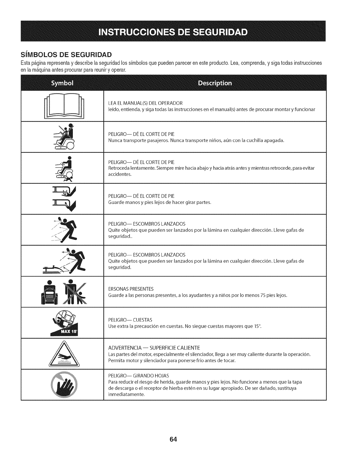
S[IVIBOLOS DE SEGURIDAD
Estap&ginarepresentay describelaseguridadlos simbolosquepuedenpareceren esteproducto.Lea,comprenda,y sigatodasinstrucciones
en lam_quinaantesprocurarparareuniry operar.
ii
®
J
®
,E,
AL
LEA EL MANUAL(S) DEL OPERADOR
leido, entienda, y siga todas las instrucciones en el manual(s) antes de procurar montar y funcionar
PELIGRO-- DE EL CORTE DE PIE
Nunca transporte pasajeros. Nunca transporte nihos, aun con la cuchilla apagada.
PELIGRO-- DE EL CORTE DE PIE
Retroceda lentamente. Siempre mire hacia abajo y hacia atr_is antes y mientras retrocede, para evitar
accidentes.
PELIGRO-- DE EL CORTE DE PIE
Guarde manos y pies lejos de hacer girar partes.
PELIGRO-- ESCOMBROS LANZADOS
Quite objetos que pueden ser lanzados por la I_imina en cualquier direcci6n. Lleve gafas de
seguridad..
PELIGRO-- ESCOMBROS LANZADOS
Quite objetos que pueden ser lanzados por la I_imina en cualquier direcci6n. Lleve gafas de
seguridad.
ERSONAS PRESENTES
Guarde alas personas presentes, a los ayudantes y a nihos por Io menos 75 pies lejos.
PELIGRO-- CUESTAS
Use extra la precauci6n en cuestas. No siegue cuestas mayores que 15°.
ADVERTENCIA-- SUPERFICIE CALIENTE
Las partes del motor, especialmente el silenciador, Ilega a set muy caliente durante la operaci6n.
Permita motor y silenciador para ponerse frio antes de tocar.
PELIGRO-- GIRANDO HOJAS
Para reducir el riesgo de herida, guarde manos y pies lejos. No funcione a menos que la tapa
de descarga o el receptor de hierba est_n en su lugar apropiado. De ser dahado, sustituya
inmediatamente.
64
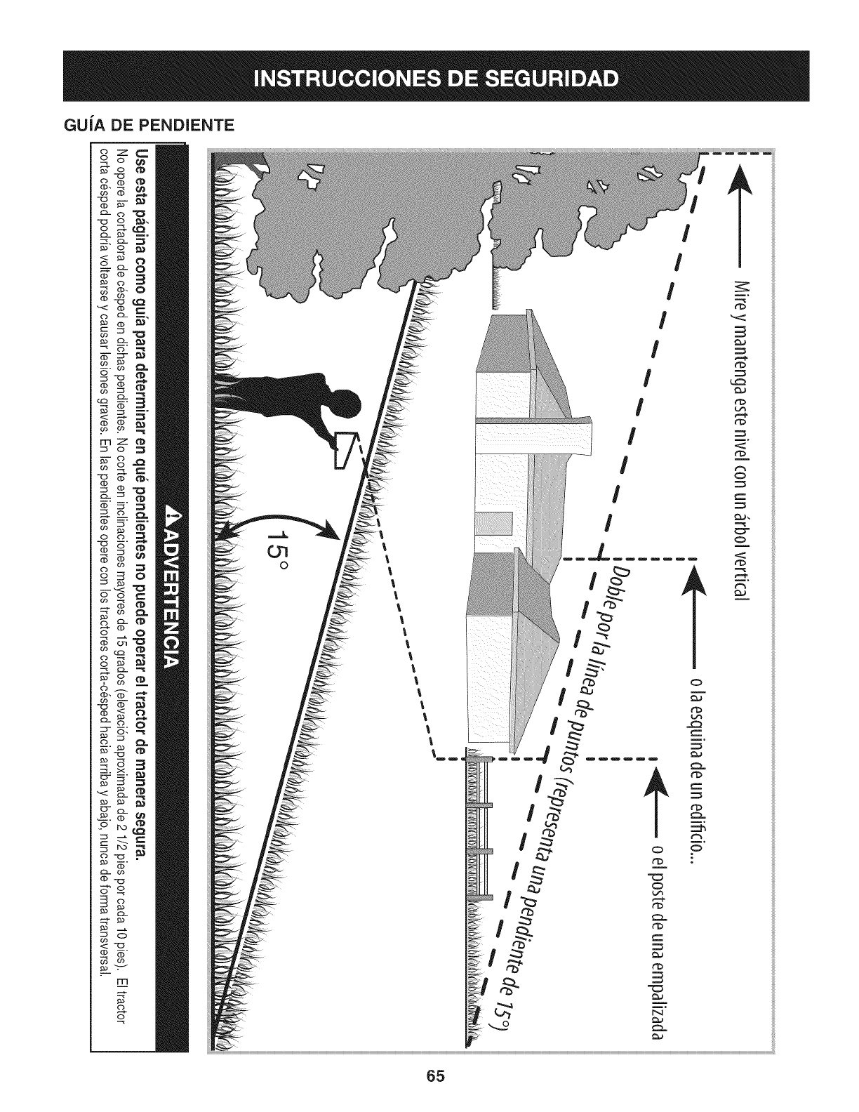
GUiA DE PENDIENTE
c)._
FT'I
('3
C)-
CD
<:
(b
rrl
o
O7
0
!
!
!
!
!
I
rb
rb
r_
r_
O
O
m°
ililililili
ililililili
ililililili
ililililili
ililililili
ililililili
ililililili
ililililili
ililililili
ililililili
ililililili
ililililili
ililililili
ililililili
ililililili
ililililili
ililililili
ililililili
ililililili
ililililili
ililililili
ililililili
ililililili
ililililili
ililililili
ililililili
ililililili
ililililili
ililililili
ililililili
ililililili
ililililili
ililililili
ililililili
ililililili
ililililili
ililililili
ililililili
ililililili
ililililili
ililililili
ililililili
ililililili
ililililili
ililililili
ililililili
ililililili
ililililili
ililililili
ililililili
ililililili
ililililili
ililililili
65
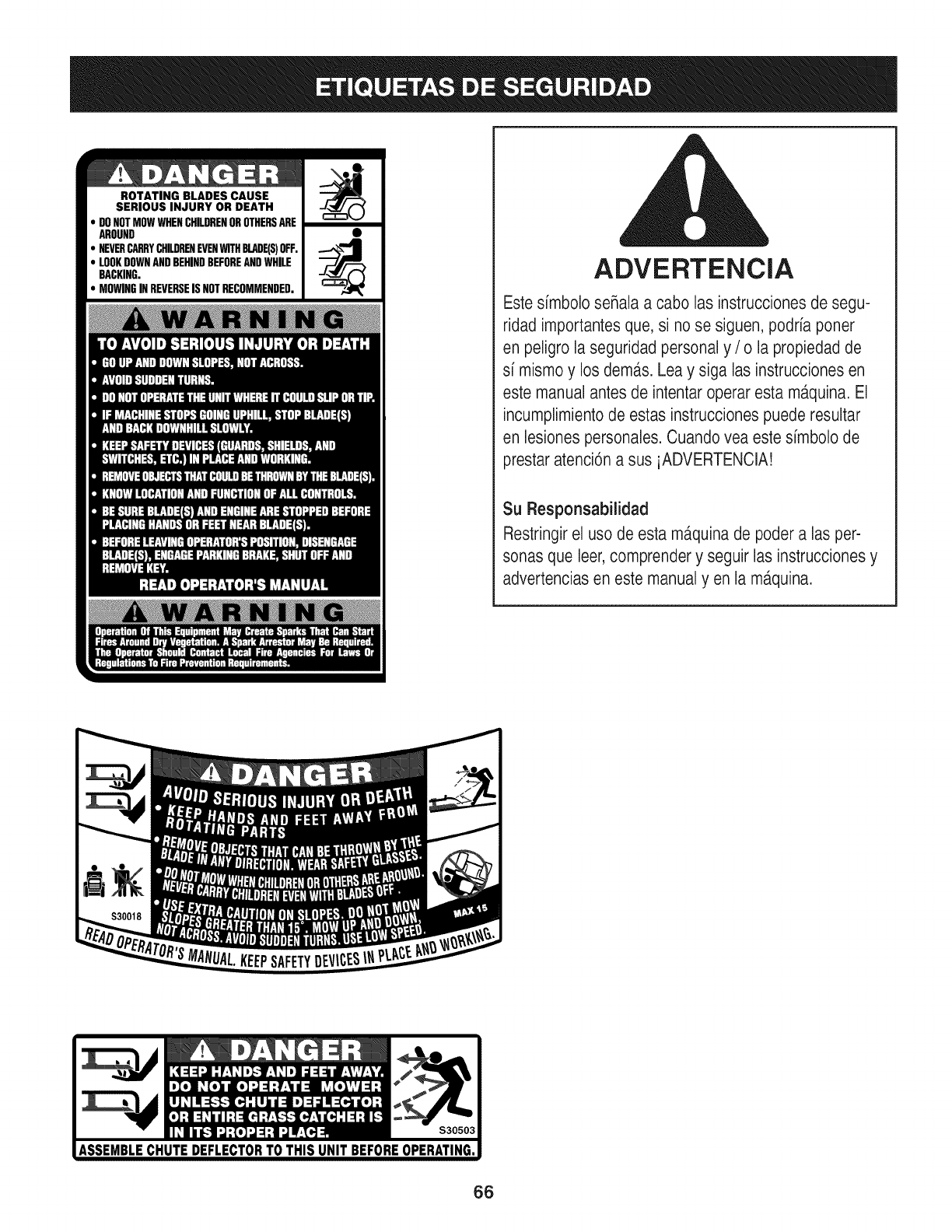
ROTATING BLADES CAUSE
SERIOUS INJURY OR DEATH
DONOTMOWWHENCHILDRENOROTHERSARE
AROUND
NEVERCARRYCHILDRENEVENWITHBLADE(S)OFF.
LOOKDOWNANDBEHINDBEFOREANDWHILE
BACKING.
MOWINGINREVERSEISNOTRECOMMENDED. ADVERTENCIA
Este simbolo seRalaa cabo las instrucciones de segu-
ridad importantesque, si no se siguen, podria poner
en peligro laseguridad personal y /o la propiedad de
si mismoy los dem,_s.Lea y siga las instrucciones en
este manual antes de intentar operar esta m_tquina.El
incumplimientode estas instruccionespuede resultar
en lesionespersonales.Cuando vea este simbolo de
prestar atenci6na sus iADVERTENCIA!
Su Responsabilidad
Restringirel uso de esta ma.quinade poder alas per-
sonas que leer,comprender y seguir las instruccionesy
advertenciasen este manualy en la m,_quina.
66
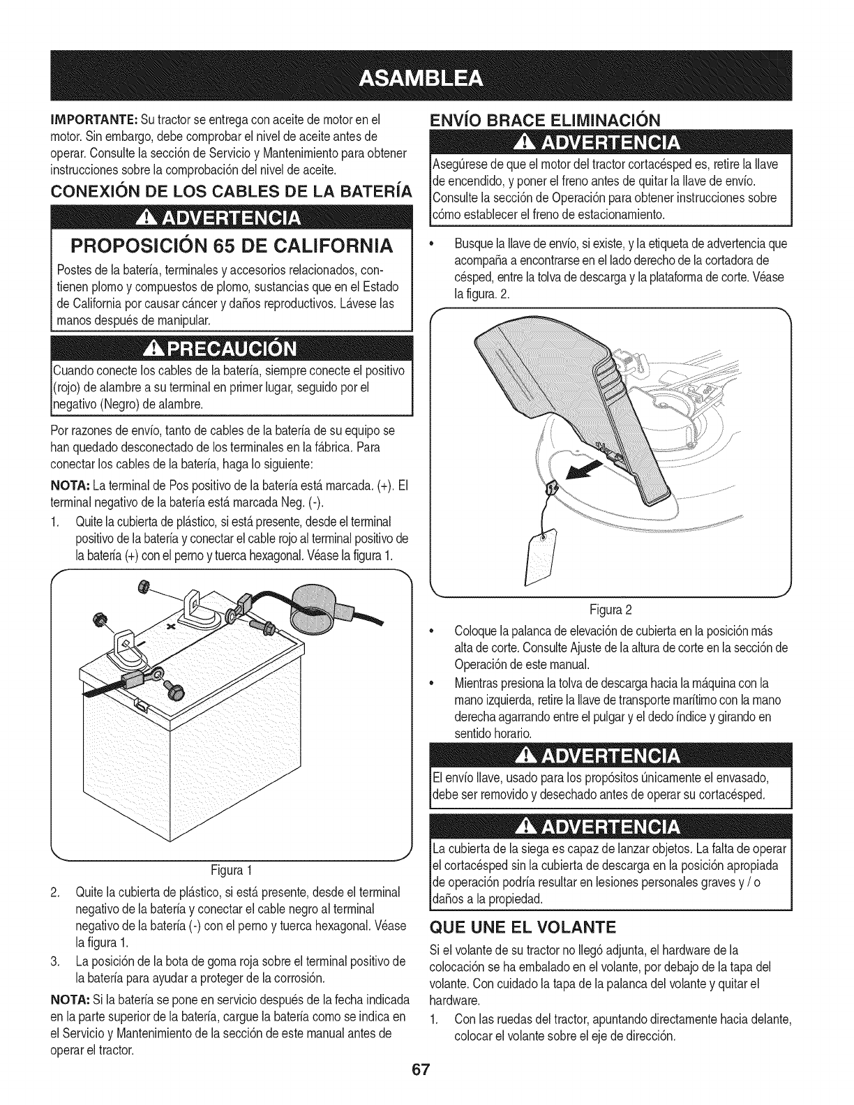
IMPORTANTE: Sutractorse entregaconaceitedemotoren el
motor.Sinembargo,debecornprobarel niveldeaceiteantesde
operar.Consultela secci6nde ServMoy Mantenirnientoparaobtener
instruccionessobrelacornprobaci6ndelnivelde aceite.
CONEXION DE LOS CABLES DE LA BATERIA
PROPOSlCION 65 DE CALiFORNiA
ENVlO BRACE ELllVIINACION
Postesdela bateria,terrninalesy accesoriosreladonados,con-
fienen plornoy cornpuestosde pJorno,sustanciasqueen el Estado
de Californiaporcausarc_.ncery daSosreproducfivos.L_.veselas
rnanosdespu_sde rnanipular.
Cuandoconecteloscablesde la bateria,siernpreconecteel posifivo
I(rojo)dealarnbrea su terminalenprimerlugar,seguidoporel
pgafivo (Negro)dealarnbre.
Porrazonesde envb, tantodecablesde la bateriade su equipose
hanquedadodesconectadode los terrninalesen laf_.brica.Para
conectarlos cablesde la bateria,hagaIo siguiente:
NOTA: La terminalde Pospositivode la bateriaest,.rnarcada.(+).El
terminalnegativode labateriaest&rnarcadaNeg.(-).
1. Quitela cubiertadepl&stico,si est&presente,desdeelterminal
positivode labateriay conectarelcablerojoalterminalpositivode
labateria(+)conel pernoy tuercahexagonal.Veaselafigura1.
f --,,
AsegQresedequeel motordel tractorcortacespedes, retirelaIlave
de encendido,y ponerel frenoantesde quitarla Ilavedeenvio.
IConsultela secci6nde Operaci6nparaobtenerinstruccionessobre
lc6rnoestaNecerel frenode estacionarniento.
Busquela Ilavedeenvio,siexiste,y laetiquetadeadvertenciaque
acornpaSaa encontrarseenel ladoderechode lacortadorade
cesped,entrelatolvadedescargay laplataforrnadecorte.Wase
la figura.2.
Figura1
2. Quitelacubiertadepl_.stico,si est,.presente,desdeel terminal
negativode la bateriay conectarel cable negroal terminal
negativode la bateria(-) con elpernoy tuercahexagonal.Wase
lafigura 1.
3. La posici6nde la botadegornarojasobreel terminalpositivode
la bateriaparaayudara protegerde lacorrosbn.
NOTA: Si labateriase poneenserviciodespuesde la fechaindicada
en lapartesuperiorde la bateria,carguela bateriacornose indicaen
el Servicioy Uantenirnientode la secci6ndeeste manualantesde
operarel tractor.
Figura2
CoJoquelapalancade elevaci6ndecubiertaen laposici6nrn_.s
altade corte.ConsulteAjustede laalturadecorteenlasecci6nde
Operaci6ndeestemanual.
MientraspresionalatoJvadedescargahaciala rn_.quinacon la
rnanoizquierda,retirela Ilavedetransporternaritirnoconla rnano
derechaagarrandoentreel pulgary el dedoindicey girandoen
sentidohorario.
ElenvioIlave,usadoparalos prop6sitosQnicarnenteel envasado,
debeser rernovidoy desechadoantesde operarsu cortacesped.
Lacubiertade lasiegaes capazdelanzarobjetos.La faltade operar
el cortac_spedsin lacubiertade descargaen la posici6napropiada
de operaci6npodriaresultarenlesionespersonalesgravesy /o I
lda_osa a propedad. j
QUE UNE EL VOLANTE
Si el voJantede su tractornoIleg6adjunta,el hardwaredela
colocaci6nse haernbaladoen el volante,pordebajode latapa del
volante.Con cuidadola tapade lapalancadelvolantey quitarel
hardware.
1. Con las ruedasdeltractor,apuntandodirectarnentehaciadelante,
colocarel volantesobreeleje dedirecci6n.
67
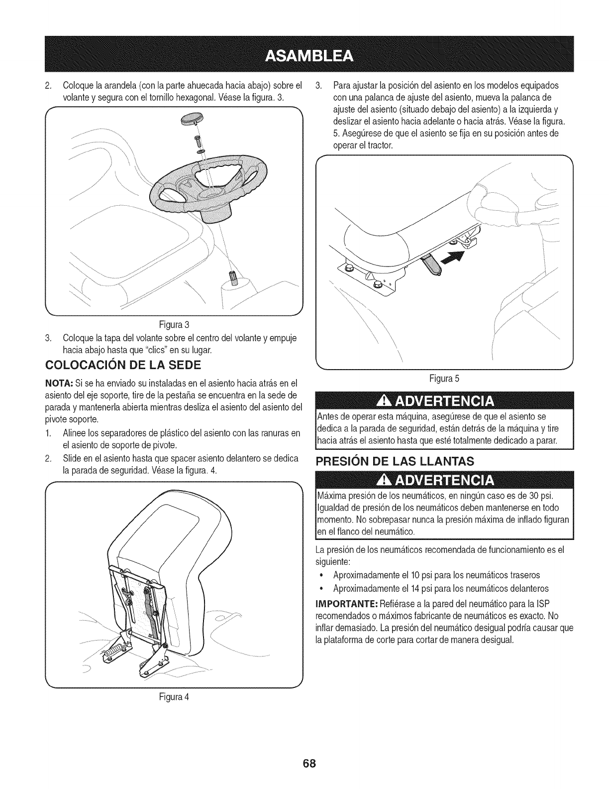
2. Coloquela arandela(con la parteahuecadahaciaabajo)sobreel
volantey seguracon el tornillohexagonal.Wase la figura.3.
f -,
Figura3
3. Coloquela tapadelvolantesobreel centrodelvolantey empuje
haciaabajohastaque"clics"en su lugar.
COLOCACI6N DE LA SEDE
NOTA: Si se haenviadosu instaladasenel asientohaciaatr_.sen el
asientodeleje soporte,tire de la pestafiase encuentraen la sedede
paraday mantenerlaabiertamientrasdeslizael asientodelasientodel
pivotesoporte.
1. Alineelos separadoresde pl_.sticodelasientocon las ranurasen
el asientode soportede pivote.
2. Slideenel asientohastaquespacerasientodelanterose dedica
la paradade seguridad.Wase la figura.4.
r
Paraajustarla posici6ndel asientoenlos modelosequipados
con unapalancade ajustedelasiento,muevala palancade
ajustedelasiento(situadodebajodelasiento)a la izquierday
deslizarel asientohaciaadelanteo haciaatr_.s.Wase lafigura.
5. AsegQresedeque elasientose fija en su posici6nantesde
operarel tractor.
\
\
Figura5
! !' =
Antesdeoperarestam_.quina,asegQresede queelasientose
dedicaa la paradadeseguridad,est_.ndetr_.sde lam_.quinay tire
[haca atr_.se asento hastaqueest_totamentededcado a parar.
PRESION DE LAS LLANTAS
M_.ximapresi6nde los neum_.ticos,en ning_ncasoes de30 psi.
Igualdadde presi6nde los neum_.ticosdebenmantenerseen todo
momento.Nosobrepasarnuncalapresi6nm_.ximade infiadofiguran
[en e f anco de neum_.tco.
Lapresi6nde los neum_.ticosrecomendadade funcionamientoes el
siguiente:
• Aproximadamenteel 10psi paralos neum_.ticostraseros
• Aproximadamenteel 14psi paralos neum_.ticosdelanteros
IMPORTANTE: Refi_rasea lapareddel neum_.ticoparala ISP
recomendadoso m_.ximosfabricantede neum_.ticoses exacto.No
inflardemasiado.Lapresi6ndel neum_.ticodesigualpodrfacausarque
laplataformade corteparacortarde maneradesigual.
Figura4
68
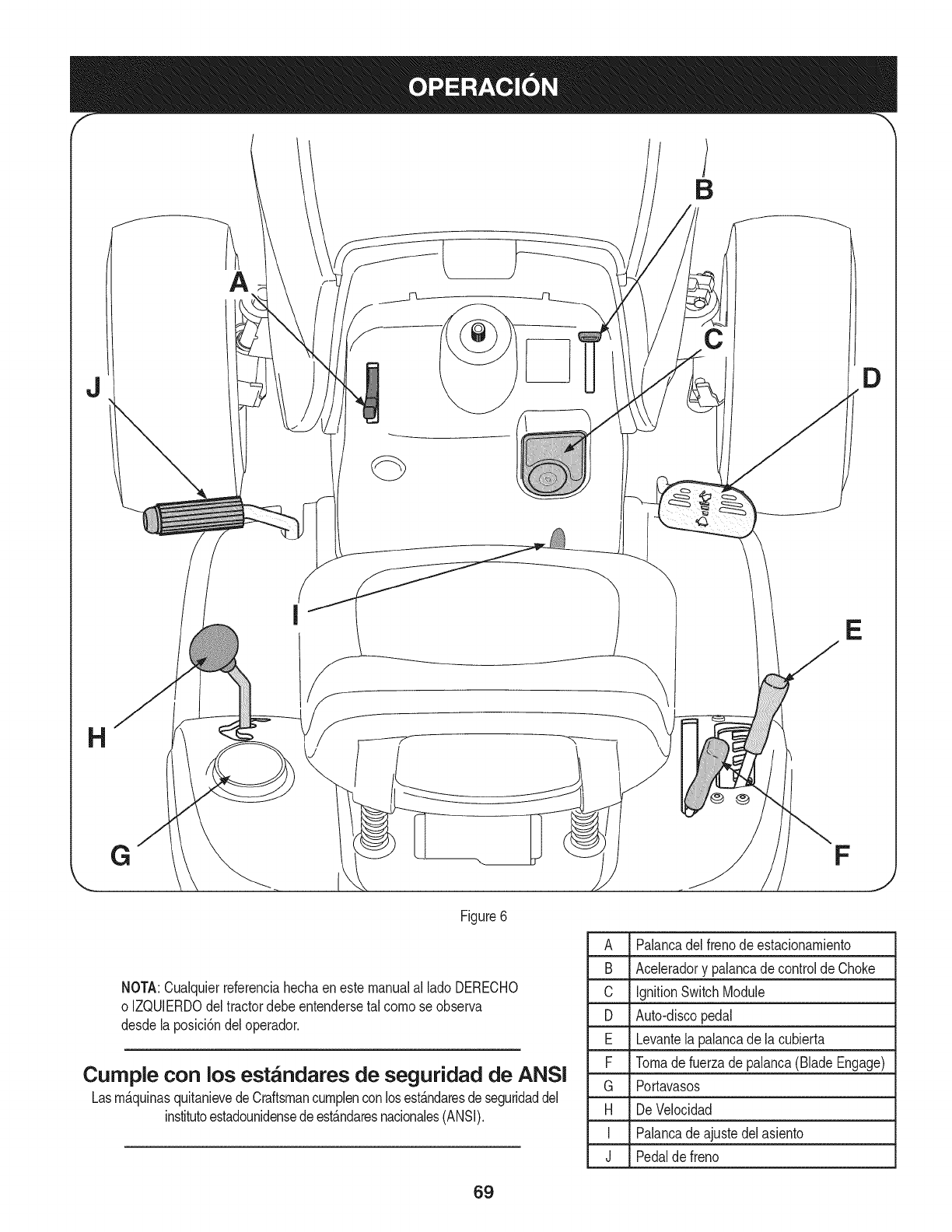
B
A
j D
E
H
G
Figure6
F
NOTA:Cualquierreferenciahechaenestemanualal ladoDERECHO
o IZQUlERDOdeltractordebeentendersetal comose observa
desdelaposici6ndeloperador.
Cumple con los est_ndares de seguridad de ANSI
Lasm_.quinasquitanievedeCraftsmancumplenconlosest_.ndaresdeseguridaddel
institutoestadounidensedeest_.ndaresnacionales(ANSI).
A Palancadel frenode estacionamiento
B Aceleradory palancadecontroldeChoke
C IgnitionSwitchModule
D Auto-discopedal
E Levantelapalancade la cubierta
F Tomadefuerzadepalanca(BladeEngage)
G Portavasos
H De Velocidad
I Palancade ajustedelasiento
J Pedalde freno
69
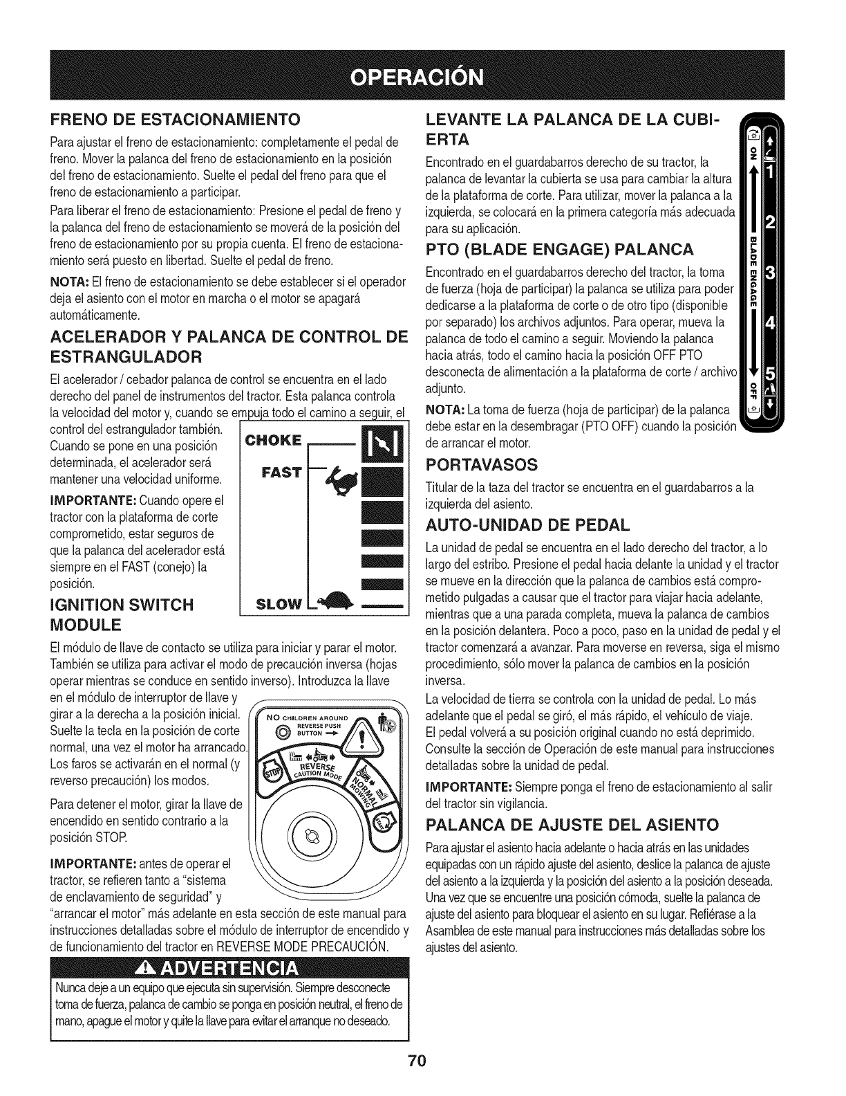
FRENO DE ESTACIONAMIENTO
Paraajustarel frenode estacionarniento:cornpletarnenteel pedalde
freno.Moverla palancadelfrenode estacionarnientoen la posici6n
delfrenode estacionarniento.Suelteel pedaldelfreno paraqueel
frenodeestacionarnientoa participar.
Paraliberarel frenode estacionarniento:Presioneelpedaldefrenoy
la palancadelfrenode estacionarnientose rnover_,dela posici6ndel
frenodeestacionarnientoporsu propiacuenta.Elfrenode estaciona-
rnientoser_.puestoen libertad.Suelteel pedalde freno.
NOTA: El frenode estacionarnientosedebeestablecersi el operador
dejaelasientocon el motorenrnarchao el motorse apagar_.
autorn_.ticarnente.
ACELERADOR Y PALANCA DE CONTROL DE
ESTRANGULADOR
Elacelerador/cebadorpalancadecontrolse encuentraen el lado
derechodel paneldeinstrurnentosdeltractor.Estapalancacontrola
lavelocidaddelmotory,cuandose ernpujatodo elcarninoa seguir,el
controldelestranguladortarnbi_n.
Cuandose poneenunaposici6n
deterrninada,el aceleradorser_.
rnantenerunavelocidaduniforrne.
IMPORTANTE: Cuandoopereel
tractorcon la plataforrnadecorte
cornprornetido,estarsegurosde
quela palancadelaceleradorest,.
siernpreen el FAST(conejo)la
posici6n.
IGNITION SWITCH
MODULE
SLOW
= EE
El rn6dulodeIlavede contactose utilizaparainiciary pararel motor.
Tarnbi_nse utilizaparaactivarel rnodode precauci6ninversa(hojas
operarrnientrasse conduceensentidoinverso).Introduzcala Ilave
enel rn6dulode interruptordeIlavey
girara laderechaa la posici6ninicial.
Sueltelateclaen laposici6ndecorte
normal,unavezel motorhaarrancado.
Losfarosse activar_.nenel normal(y
reversoprecauci6n)los rnodos.
Paradetenerel motor,girarla Ilavede
encendidoen sentidocontrarioa la
posici6nSTOR
IMPORTANTE: antesdeoperarel
tractor,se refierentantoa "sisterna
deenclavarnientode seguridad"y
"arrancarel motor"rn_.sadelanteen estasecci6nde estemanualpara
instruccionesdetalladassobreelrn6dulodeinterruptorde encendidoy
defuncionarnientodeltractorenREVERSEMODEPRECAUCION.
Nuncadejea unequipoqueejecutasinsupervisi6n.Siernpredesconecte
tornadefuerza,palancadecarnbiosepongaenposici6nneutral,elfrenode
rnano,apagueelmotoryquitelaIlaveparaevitarelarranquenodeseado.
LEVANTE LA PALANCA DE LA CUBI-
ERTA
Encontradoenel guardabarrosderechodesu tractor,la
palancadelevantarlacubiertase usa paracarnbiarlaaltura
de la plataforrnadecorte. Parautilizar,moverla palancaa la
izquierda,secolocar_,en laprirneracategoriarn_.sadecuada
parasu aplicaci6n.
PTO (BLADE ENGAGE) PALANCA
Encontradoenel guardabarrosderechodeltractor,latorna
de fuerza(hojade participar)la palancase utilizaparapoder
dedicarsea laplataforrnade corteo deotrotipo (disponible
por separado)los archivosadjuntos.Paraoperar,rnuevala
palancadetodoel carninoa seguir.Moviendola palanca
haciaatr_.s,todo elcarninohacia laposici6nOFFPTO
desconectade alirnentaci6na laplataforrnade corte/ archivo
adjunto.
NOTA: Latornadefuerza(hojade participar)de lapalanca
debeestarenla desernbragar(PTOOFF)cuandola posici6n
de arrancarel motor.
PORTAVASOS
Titularde la tazadeltractorse encuentraenel guardabarrosa la
izquierdadelasiento.
AUTO-UNIDAD DE PEDAL
Launidadde pedalse encuentraenel ladoderechodel tractor,a Io
largodelestribo.Presioneel pedalhaciadelantela unidady el tractor
se rnueveen ladirecci6nquela palancadecarnbiosest,.cornpro-
rnetidopulgadasa causarqueel tractorparaviajar haciaadelante,
rnientrasquea unaparadacornpleta,rnuevala palancade carnbios
en la posici6ndelantera.Pocoa poco,pasoenla unidadde pedaly el
tractorcornenzar_,a avanzar.Pararnoverseen reversa,sigael rnisrno
procedirniento,s61omoverla palancadecarnbiosenla posici6n
inversa.
Lavelocidaddetierra se controlaconla unidadde pedal.Lorn_.s
adelantequeel pedalsegir6, elrn_.sr_.pido,elvehiculode viaje.
Elpedalvolver_,a su posici6noriginalcuandono est,.deprirnido.
Consultela secci6nde Operaci6nde estemanualparainstrucciones
detalladassobrelaunidadde pedal.
IMPORTANTE: Siernprepongael frenodeestacionarnientoal salir
del tractorsinvigilancia.
PALANCA DE AJUSTE DEL ASIENTO
Paraajustarelasientohaciaadelanteo haciaatr_.senlasunidades
equipadasconunr_.pidoajustedelasiento,deslicelapalancadeajuste
delasientoa laizquierday laposici6ndelasientoa laposici6ndeseada.
Unavezqueseencuentreunaposici6nc6rnoda,sueltelapalancade
ajustedelasientoparabloquearelasientoensulugar.Refi_raseala
Asarnbleadeestemanualparainstruccionesrn_.sdetalladassobrelos
ajustesdelasiento.
70
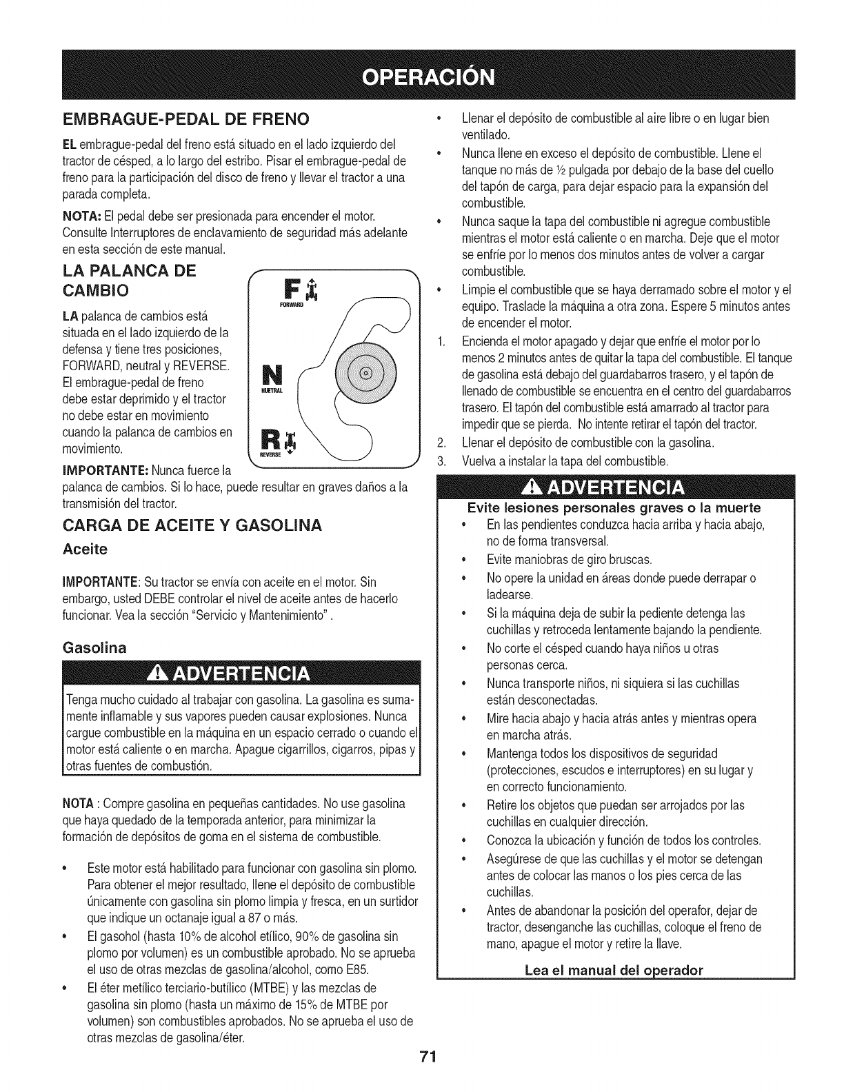
EMBRAGUE-PEDAL DE FRENO
ELernbrague-pedaldelfreno est_situadoen el ladoizquierdodel
tractorde c_sped,a Io largodelestribo.Pisarel ernbrague-pedalde
frenoparala participaci6ndeldiscodefrenoy Ilevarel tractora una
paradacornpleta.
NOTA: Elpedaldebeser presionadaparaencenderel motor.
ConsulteInterruptoresde enclavarnientode seguridadrn_sadelante
enestasecci6ndeestemanual.
LA PALANCA DE f
cAMBIo F ;i;
LA palancade carnbiosest_
situadaenel ladoizquierdode la
defensay tienetresposiciones,
FORWARD,neutraly REVERSE.
Elernbrague-pedalde freno
debeestardeprirnidoy el tractor
nodebeestarenrnovirniento
cuandola palancade carnbiosen
rnovirniento.
IMPORTANTE: Nuncafuercela
palancade carnbios.Si Io hace,puederesultarengravesdaSosa la
transrnisi6ndel tractor.
CARGA DE ACEITE Y GASOLINA
Aceite
IMPORTANTE:Sutractorse enviacon aceiteen el motor.Sin
embargo,ustedDEBEcontrolarel nivelde aceiteantesde hacerlo
funcionar.Vealasecci6n"Servicioy Mantenirniento".
Gasolina
Tengarnuchocuidadoal trabajarcon gasolina.Lagasolinaes surna-
rnenteinfiarnabley susvaporespuedencausarexplosiones.Nunca
carguecombustibleenla rn_.quinaenun espaciocerradoo cuandoel
motorest&calienteoen rnarcha.Apaguecigarrillos,cigarros,pipasy
otrasfuentesde cornbusti6n.
NOTA: Cornpregasolinaen pequeSascantidades.No usegasolina
quehayaquedadode laternporadaanterior,pararninirnizarla
forrnaci6nde dep6sitosdegornaen elsisternadecombustible.
• Estemotorest&habilitadoparafuncionarcongasolinasin plorno.
Paraobtenerelrnejorresultado,Ileneel dep6sitodecombustible
0nicarnentecongasolinasin plornolirnpiay fresca,enun surtidor
queindiqueunoctanajeiguala 87o rn_.s.
• Elgasohol(hasta10%dealcoholefilico,90%de gasolinasin
plornoporvolurnen)es un combustibleaprobado.No seaprueba
el usode otrasrnezclasdegasolina/alcohol,cornoE85.
• El_ter rnefilicoterciario-bufilico(MTBE)y las rnezclasde
gasolinasin plorno(hastaun rn&xirnode 15%de MTBEpor
volurnen)son combustiblesaprobados.Nose apruebael uso de
otrasrnezclasdegasolina/eter.
• Llenareldep6sitodecombustiblealaire libreo en lugarbien
ventilado.
• NuncaIleneen excesoel dep6sitode combustible.Lleneel
tanquenorn&sde 1/2pulgadapordebajode labasedel cuello
del tap6ndecarga,paradejarespacioparalaexpansi6ndel
combustible.
• Nuncasaquela tapadel combustibleniagreguecombustible
rnientrasel motorest&calienteo enrnarcha.Dejequeel motor
seenfrie porIornenosdos rninutosantesde volvera cargar
combustible.
• Lirnpieel combustiblequese hayaderrarnadosobreel motory el
equipo.Trasladelarn&quinaa otrazona.Espere5 rninutosantes
de encenderelmotor.
1. Enciendael motorapagadoy dejarqueenfrieel motorporIo
rnenos2 rninutosantesdequitarlatapadelcombustible.Eltanque
degasolinaest&debajodelguardabarrostrasero,y eltap6nde
Ilenadode combustiblese encuentraenelcentrodelguardabarros
trasero.Eltap6ndelcombustibleest&arnarradoaltractorpara
irnpedirquese pierda. Nointenteretirareltap6ndeltractor.
2. Llenareldep6sitodecombustiblecon lagasolina.
3. Vuelvaa instalarla tapadel combustible.
Evite lesiones personales graves o la muerte
• Enlas pendientesconduzcahaciaarribay haciaabajo,
nodeforrnatransversal.
• Eviternaniobrasdegirobruscas.
• 1/ooperelaunidaden &reasdondepuedederraparo
ladearse.
• Sila rn_.quinadejade subirla pedientedetengalas
cuchillasy retrocedalentarnentebajandola pendiente.
• 1/ocorteel c_spedcuandohayaniSosu otras
personascerca.
• NuncatransporteniSos,nisiquierasi las cuchillas
est&ndesconectadas.
• Mirehaciaabajoy haciaatr&santesy rnientrasopera
en rnarchaatr&s.
• Mantengatodoslos dispositivosde seguridad
(protecciones,escudose interruptores)en su lugary
en correctofuncionarniento.
• Retirelosobjetosquepuedanser arrojadosporlas
cuchillasen cualquierdirecci6n.
• Conozcala ubicaci6ny funci6ndetodoslos controles.
• Aseg0resede quelascuchillasy el motorse detengan
antesdecolocarlas rnanoso los piescercade las
cuchillas.
• Antesdeabandonarla posici6ndel operafor,dejarde
tractor,desenganchelas cuchillas,coloqueelfrenode
rnano,apagueel motory retirelaIlave.
71
Lea el manual del o erador
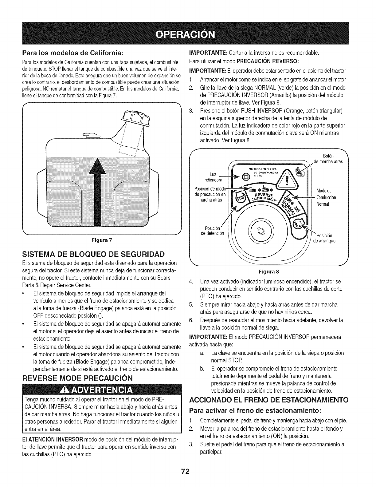
Para los modelos de California:
ParalosmodelosdeCaliforniacuentanconunatapasujetada,elcombustible
detrinquete,STOPIlenareltanquedecombustibleunavezqueseveelinte-
riordelabocadeIlenado.Estoaseguraqueunbuenvolumendeexpansi6nse
creaIocontrario,eldesbordamientodecombustiblepuedecrearunasituaci6n
peligrosa.NOrematareltanquedecombustible.EnlosmodelosdeCalifornia,
IleneeltanquedeconformidadconlaFigura7.
Figura7
SISTENIA DE BLOQUEO DE SEGURIDAD
El sistemade bloqueode seguridadest,.dise_adoparala operaci6n
seguradel tractor.Si estesistemanuncadejadefuncionarcorrecta-
rnente,noopereel tractor,contacteinmediatamentecon su Sears
Parts& RepairServiceCenter.
• El sistemade bloqueode seguridadimpideel arranquedel
vehiculoa menosque elfrenode estacionamientoy se dedica
a latomadefuerza(BladeEngage)palancaest,.en laposici6n
OFFdesconectadoposici6nO.
• El sistemade bloqueode seguridadseapagar_autom_ticamente
el motorsi el operadordejael asientoantesde iniciarel frenode
estacionamiento.
• El sistemade bloqueode seguridadseapagar_autom_ticamente
el motorcuandoel operadorabandonasuasientodel tractorcon
latomade fuerza(BladeEngage)palancacomprometido,inde-
pendientementede si est,.activadoel frenodeestacionamiento.
REVERSE MODE PRECAUCION
Tengamuchocuidadoal operarel tractoren el modode PRE-
CAUCIONINVERSA.Siernpremirarhaciaabajoy haciaatr_.santes
dedar marchaatr_.s.Nohagafuncionarel tractorcuandolos ni_osu
otraspersonasalrededor.Pararel tractorinmediatamentesi alguien
entraenel _.rea.
El ATENCK)NINVERSORmodode posici6ndel m6dulode interrup-
tor deIlavepermitequeeltractorparaoperaren sentidoinversocon
las cuchillas(PTO)haejercido.
IMPORTANTE: Cortara la inversanoes recomendable.
Parautilizarel modoPRECAUCIONREVERSO:
IMPORTANTE:Eloperadordebeestarsentadoenelasientodeltractor.
1. Arrancarelmotorcomose indicaenelepigrafedearrancarelmotor.
2. Girela llavede lasiega NORMAL(verde)laposici6nenel modo
de PRECAUCIONINVERSOR(Amarillo)la posici6ndel m6dulo
de interruptordeIlave.VerFigura8.
3. Presioneel bot6nPUSHINVERSOR(Orange,bot6ntriangular)
en laesquinasuperiorderechade lateclade m6dulode
conmutaci6n.La luzindicadoradecolor rojoenla partesuperior
izquierdadel m6dulodeconmutaci6nclaveser_ON mientras
activado.Ver Figura8.
f
Bot6n
de marchaatr_.s
Luz
indicadora
Dosici6nde Modode
deprecauci6nen
marchaatrb,s Conducci6n
Normal
de detenci6n
de arranque
Figura 8
4. Unavezactivado(indicadorluminosoencendido),el tractorse
puedenconduciren sentidocontrariocon lascuchillasdecorte
(PTO) haejercido.
5. Siempremirarhaciaabajoy haciaatr_.santesde darmarcha
atr_.sparaasegurarsede quenohay ni_oscerca.
6. Despu_sde reanudarel movimientohaciaadelante,devolverla
Ilavea la posici6nnormalde siega.
IMPORTANTE: El modoPRECAUCIONINVERSORpermanecer_
activadahastaque:
a. Laclavese encuentraen la posici6nde la siegaoposici6n
normalSTOR
b. Eloperadorse comprometeel frenodeestacionamiento
totalmentedeprimenteel pedaldefrenoy mantenerla
presionadamientrasse muevela palancade controlde
velocidadenla posici6nde frenode estacionamiento.
ACCIONADO EL FRENO DE ESTACIONAlVUENTO
Para activar el freno de estacionamiento:
1. Completamenteelpedaldefrenoy mantengahaciaabajoconel pie.
2. Moverla palancadel frenodeestacionamientohastael rondoy
en elfrenode estacionamiento(ON)la posici6n.
3. Suelteel pedaldel frenoparaqueel frenodeestacionamientoa
participar.
72
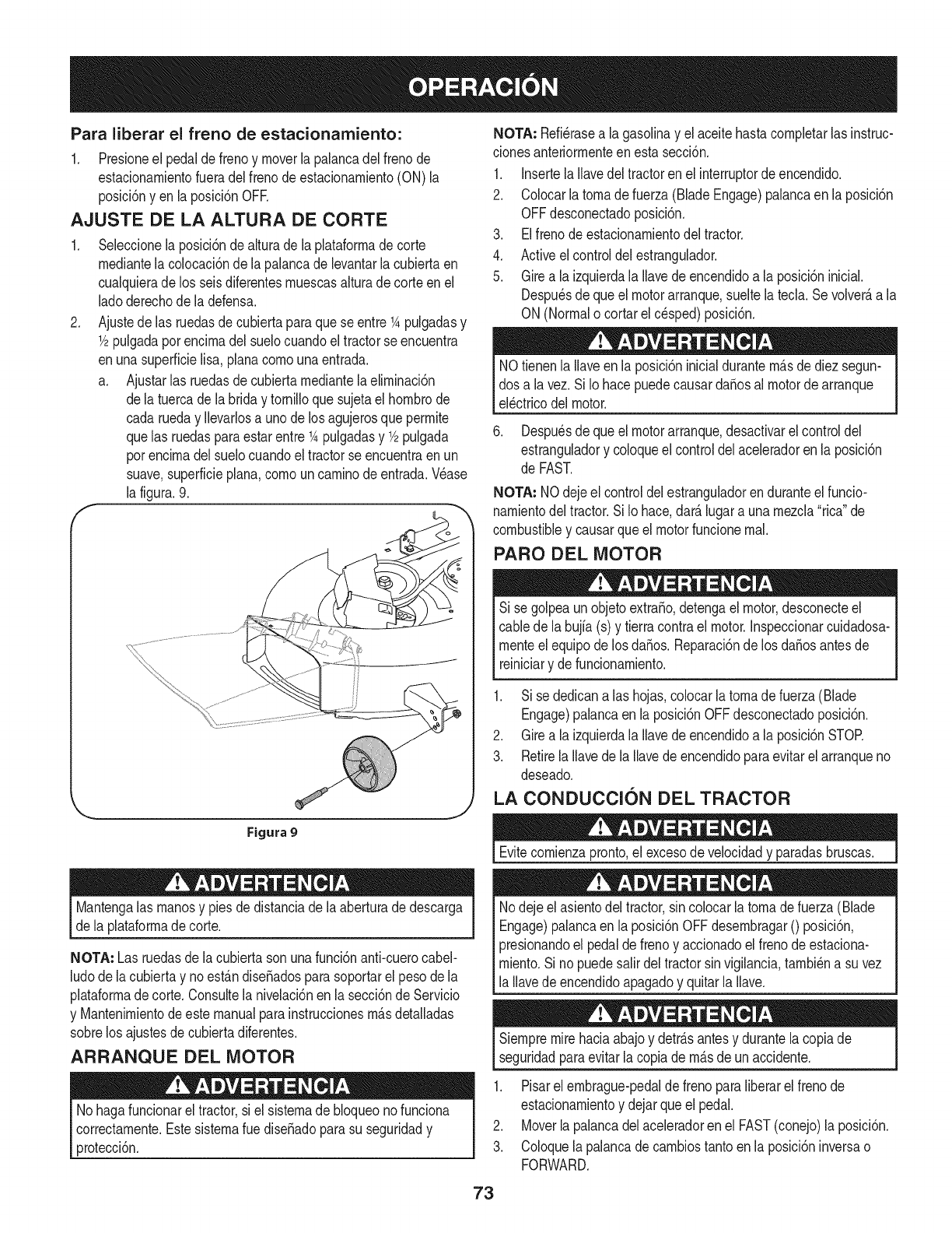
Para liberar el freno de estacionamiento:
1. Presioneel pedaldefrenoy moverla palancadelfrenode
estacionarnientofueradel frenodeestacionarniento(ON) la
posici6nyen laposici6nOFR
AJUSTE DE LA ALTURA DE CORTE
.
F
Seleccionela posici6nde alturadela plataforrnade corte
rnediantela colocaci6nde la palancade levantarlacubiertaen
cualquierade los seisdiferentesrnuescasalturade corteenel
ladoderechode ladefensa.
Ajustede las ruedasdecubiertaparaquese entre 1Apulgadasy
1/2pulgadaporencirnadel suelocuandoeltractorse encuentra
enunasuperficielisa,planacornounaentrada.
a. Ajustarlas ruedasde cubiertarnediantela elirninaci6n
dela tuercade la briday tornilloquesujetael hornbrode
cada rueday Ilevarlosa unode losagujerosque perrnite
quelas ruedasparaestarentre1Apulgadasy 1/2pulgada
porencirnadel suelocuandoel tractorse encuentraen un
suave,superficieplana,cornouncarninodeentrada.Wase
la figura.9.
NOTA: Refi_rasea la gasolinay el aceitehastacornpletarlasinstruc-
clonesanteriorrnenteenestasecci6n.
1. Insertela Ilavedeltractorenel interruptordeencendido.
2. Colocarla tornade fuerza(BladeEngage)palancaen la posici6n
OFFdesconectadoposici6n.
3. Elfrenodeestacionarnientodeltractor.
4. Activeel controldelestrangulador.
5. Girea la izquierdala Ilavede encendidoa la posici6ninicial.
Despu_sde queel motorarranque,sueltelatecla. Sevolver_,a la
ON(Normalo cortarel c_sped)posici6n.
NOtienenla Ilaveen la posici6ninicialdurantern_.sde diezsegun-
dos a lavez. SiIo hacepuedecausardafiosal motorde arranque
el_ctricodelmotor.
6. Despu_sde queel motorarranque,desactivarel controldel
estranguladory coloqueel controldelaceleradorenla posici6n
de FAST.
NOTA: NOdejeel controldelestranguladorenduranteelfuncio-
narnientodel tractor.SiIo hace,dar_.lugarauna rnezcla"rica"de
combustibley causarqueel motorfuncionernal.
PARO DEL MOTOR
Si se golpeaunobjetoextrafio,detengael motor,desconecteel
cablede la bujfa(s) y tierracontrael motor.Inspeccionarcuidadosa-
rnenteel equipode losdafios. Reparaci6nde los dafiosantesde
reiniciary defuncionarniento.
Figura 9
Mantengalas rnanosy piesde distanciade laaberturade descarga
de la plataforrnadecorte.
NOTA: Las ruedasde lacubiertasonunafunci6nanti-cuerocabel-
ludodela cubiertay noest_.ndisefiadosparasoportarel pesode la
plataforrnadecorte. Consultelanivelaci6nen lasecci6ndeServicio
y Mantenirnientodeestemanualparainstruccionesrn_.sdetalladas
sobrelos ajustesdecubiertadiferentes.
ARRANQUE DEL MOTOR
No hagafuncionareltractor,si el sisternade bloqueonofunciona
correctarnente.Estesisternaruedisefiadoparasu seguridady
protecci6n.
1. Sise dedicana las hojas,colocarlatornadefuerza(Blade
Engage)palancaen la posici6nOFFdesconectadoposici6n.
2. Girea la izquierdala Ilavede encendidoa la posici6nSTOR
3. RetirelaIlavede la Ilavede encendidoparaevitarelarranqueno
deseado.
LA CONDUCCION DEL TRACTOR
Evitecornienzapronto,el excesodevelocidady paradasbruscas.
Nodejeel asientodel tractor,sincolocarlatornadefuerza(Blade
Engage)palancaen laposici6nOFFdesernbragar0 posici6n,
presionandoel pedalde frenoy accionadoel frenode estaciona-
rniento.Si no puedesalirdeltractorsin vigilancia,tarnbi_na suvez
la Ilavedeencendidoapagadoy quitarla Ilave.
Siernpremirehaciaabajoy detr_.santesy durantelacopiade
seguridadparaevitarla copiade rn_.sde unaccidente.
1. Pisarel ernbrague-pedaldefreno paraliberarel frenode
estacionarnientoy dejarqueel pedal.
2. Moverlapalancadel aceleradorenel FAST(conejo)la posici6n.
3. Coloquelapalancadecarnbiostantoenla posici6ninversao
FORWARD.
73
NOTA: Siernpreoperarel tractorconla palancade controldel
aceleradoren el FAST(conejo)laposM6nparael usorn_.sefMente
de laplataforrnade corteode otrofipo (disponibleporseparado)los
archivosadjuntos.
4, Pocoa pococornienzana ejercerpresi6nen launidadde pedal,
Cuantom&sabajoel pedalse empuja,rn&srapidoqueel tractor
se desplazar_,enla direcd6ndeseadasobrelabasede la
posici6ndela palancade carnbios,
5, Eltractordecespedes Ilevadoa unaparadaporla liberaci6nde
la unidaddepedaly luegooprirnirel pedalde freno,
NOintentecarnbiarla direcd6nde la rnarchacuandoel tractor
est_en rnovirniento.SiernpreIleveeltractora unaparadacompleta
antesde moverlapalancade controlde velocidadhaciaadelantea
atr_.so viceversa,Elno hacerlopodriaresultaren seriosdaSosa la
transrnisi6nde su tractor,
IMPORTANTE"Enprimerlugartiernpo,los operadoresdebenutilizar
velocidadesrn_.slentas.Convi_rtetetotalrnentefarniliarizadocon el
funcionarnientodel tractory loscontrolesantesdeoperarel tractoren
unamayorvelocidad.
AI pararel tractor,porcualquierrnotivo,rnientrasqueen unasuperficie
de hierba,siernpre:
1. Coloquela palancadecarnbiosenpuntornuerto,
2. Apliqueelfreno deestacionarniento,
3. Apagueel motory quitarla Ilave.Si Iohace,reducir_,al rninirnola
posibilidadde quesu c_spedse dore""porelescapecalientedel
motorde sutractor.
Antesdeabandonarla posici6ndeloperadorporcualquierraz6n,
separarlas hojas,ponerlapalancade controlde velocidaden
I neutral,pongaelfreno deestacionarniento,paradamotorapagadoy
_quitarla Ilave.
CONDUCCIC)N EN LAS LADERAS
Refierenalanchode la pendienteen laseguridadde laspr_.cticasde
operaci6nirnportantesecci6ndel manualparaayudara deterrninar
zonasde laderadondepuedeoperarel tractorcontotalseguridad.
Nocorteel cespedenpendientescon unainclinaci6ndern_.sde 15
grados(unaurnentode aproxirnadarnente2-1/2piescada 10pies).
Eltractorpuedevolcary causarlesionesgraves.
• Corteel cespedy las pendientes,nuncatransversal.
Tengaextrernaprecauci6nal carnbiardedirecci6nenlas
pendientes.
Watchparalosagujeros,grietas,baches,piedrasu otrosobjetos
ocultos.Terrenoirregularpuederevertirlarn_.quina.Elcesped
alto puedeocultarobst_.culos.
Evitegirarcuandose circulapor unapendiente.Si unavez,debe
hacerse,a su vezporla pendiente.Elregresode unapendiente
aurnentala posibilidaddeun rollover.
Evitedetenersecuandose conduceporunapendiente.Si es
necesariodetenerrnientrasse conducepot unapendiente,
puestaen rnarchasin problernasy concuidadoparareducirla
posibilidaddevoltearel tractorhaciaatr_.s.
INVOLUCRAR A LOS BLADES
Participaci6ndelatornadefuerza(BladeEngage)lastransferenciasde
energiaa la plataforrnadecorteo deotrotipo(disponibleporseparado)
los archivosadjuntos.Paraparticipardelas hojas,hagaIosiguiente:
1. Moverla palancade controldelaceleradora la r_.pida(conejo)la
posici6n.
2. Sujetela tornade fuerza(BladeEngage)y girarla palancade
todo elcarninoa seguira los novios(ON)la posici6n.
3. Mantengalapalancadel aceleradorenel FAST(conejo)la
posici6nparael usorn_.seficientede la plataforrnade corteo de
otto tipo (disponibleporseparado)los archivosadjuntos.
IMPORTANTE: Enel reversoPrecauci6nrnodoqueel motorse
apagar_,autorn_.ticarnentesi latornadefuerzaest,.comprornetidacon
la palancade controldevelocidadenla posici6ninversaparaviajar
con la Ilavedeencendidoenla posici6nnormalde siega.
USO DE LA CUBIERTA DE LEVANTE LA
PALANCA DE
Paraelevarlaplataforrnade corte,moverla palancadeelevaci6nde
cubiertaa la izquierda,luegosecolocaenla ranurarn_.sadecuada
parasu aplicaci6n.ConsulteAjustelaalturade corteanteriorrnenteen
estasecci6n.
74
CORTAR
ParaayudaraevJtarelcontactocon lacuchJllao una lesJ6nen
elobjetolanzado,Mantengaa losespectadores,losayudantes,
los niSosy las mascotasporIo menos75piesde distanciade la
m_.quinamientrasest,.en funcionamiento.Paradade la m_.quina,si
alguienentraenel _.rea.
La sJguJenteinformacJ6nser_.Qtilcuandose utilizalaplataformade
cortecon sutractor:
Plande su patr6nde corteparaevitarla descargade materiales
hacialas carreteras,aceras,transeQntes,etc.Adem_.s,evitematerial
quese descargacontraunaparedo unaobstrucci6nquepuede
causaraltamateriala rebotarhaciael operador.
FAROS
• LasI_.mparasest_.nONcuandoel motordeltractorse est,.
ejecutando.
• Laslucesse apagacuandolaIlavedecontactose muevea la
posici6nSTOE
• No corteel c6speda la velocidaddeterrenoelevado,especial-
mentesi se ha instaladoun kitde mantilloo colectorde cesped.
• Paraobtenerlos mejoresresultadosse recomiendaquelas
dos primerasvueltassecortar&con laaprobad6nde la gesti6n
arrojadohaciael centro.Traslasdos primerasvueltas,invertirel
sentidodelanzarla descargahaciael exteriorde labalanzade
corte.Estoledar&unamejoraparienciaal c6sped.
• No corteel cespeddemasiadocorto.Pastocortoinvitacrec-
imientodemalashierbasy los amarilloscon rapidezenel tiempo
seco.
Cortarel c6spedsiemprese debehacercon el motora todogas.
• Bajolascondicionesm_.spesadas,puedesernecesariovolversobre
lazonadelcorteporsegundavezparaobteneruncortelimpio.
NOintentecortarespesamalezay malashJerbasyelpastomuyalto.
Sutractorest&diseSadoparacortarelc6sped,uncepillonoest&claro.
Mantengalascuchillasafiladasy sustituirlascuchillasencaso
dedesgaste.ConsulteHojasdecorteenel servicioy la secci6n
Mantenimientode estemanualdeinstruccionesde afilarla hoja
adecuada.
75
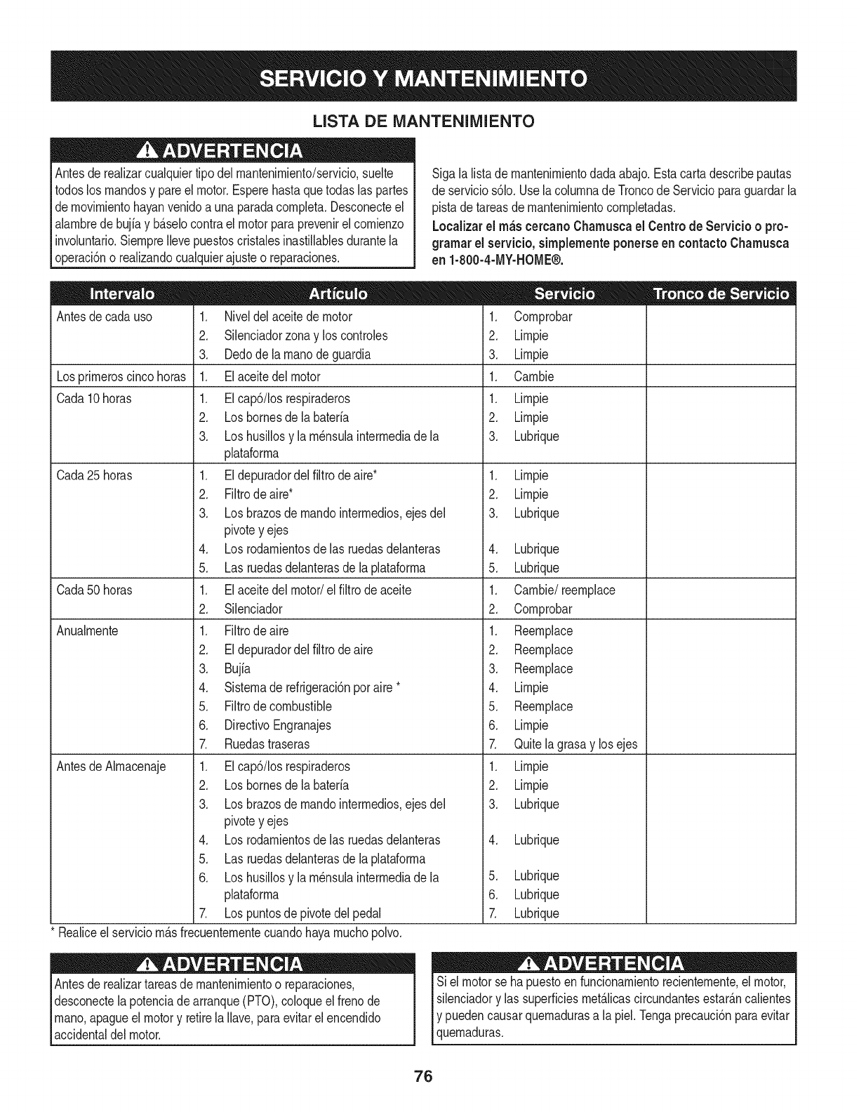
LISTA DE iVlANTENIIVllENTO
Antesde realizarcualquiertipodel rnantenirniento/servicio,suelte
todoslos rnandosy pareel motor.Esperehastaquetodaslas partes
dernovirnientohayanvenidoa unaparadacornpleta.Desconecteel
alarnbrede bujiay b_.selocontraelmotorparaprevenirel cornienzo
involuntario.SiernpreIlevepuestoscristalesinastillablesdurantela
operaci6no realizandocualquierajusteo reparaciones.
Sigala listade rnantenirnientodadaabajo.Estacartadescribepautas
de servicios61o.Usela colurnnade Troncode Servicioparaguardarla
pistade tareasdernantenirnientocornpletadas.
Localizarel rn_scereanoCharnuscael Centrode Servicio o pro-
grarnar el servicio,sirnplementeponerseen eontactoChamusca
en 1-800-4-MY-HOME®.
Antesde cadauso
Losprirneroscincohoras
Cada10horas
Cada 25 horas
Cada50horas
Anualrnente
Antesde Alrnacenaje
1. Niveldelaceitedemotor
2. Silenciadorzonay los controles
3. Dedode la rnanodeguardia
1. Elaceitedel motor
1. EIcap6/Ios respiraderos
2. Losbornesdela bateria
3. Loshusillosy la rn_nsulainterrnediade la
plataforrna
1. Eldepuradordelfiltrode aire*
2. Filtrode aire*
3. Losbrazosde rnandointerrnedios,ejes del
pivotey ejes
4. Losrodarnientosdelas ruedasdelanteras
5. Las ruedasdelanterasdela plataforrna
1. Elaceitedel motor/el filtrodeaceite
2. Silenciador
1. Filtrodeaire
2. Eldepuradordelfiltrode aire
3. Bujia
4. Sisternade refrigeraci6nporaire *
5. Filtrode combustible
6. DirectivoEngranajes
7. Ruedastraseras
1. EIcap6/Iosrespiraderos
2. Losbornesdela bateria
3. Losbrazosde rnandointerrnedios,ejes del
pivotey ejes
4. Losrodarnientosdelas ruedasdelanteras
5. Las ruedasdelanterasdela plataforrna
6. Loshusillosy la rn_nsulainterrnediade la
plataforrna
7. Lospuntosde pivotedelpedal
* Realiceel serviciorn_.sfrecuenternentecuandohayarnuchopolvo.
Antesde realizartareasdernantenirnientoo reparaciones,
desconectelapotenciadearranque(PTO),coloqueel frenode
rnano,apagueel motory retirela Ilave,paraevitarelencendido
accidentaldel motor.
1. Cornprobar
2. Lirnpie
3. Lirnpie
1. Carnbie
1. Lirnpie
2. Lirnpie
3. Lubrique
1. Lirnpie
2. Lirnpie
3. Lubrique
4. Lubrique
5. Lubrique
1. Carnbie/reernplace
2. Cornprobar
1. Reernplace
2. Reernplace
3. Reernplace
4. Lirnpie
5. Reernplace
6. Lirnpie
7. Quitelagrasay losejes
1. Lirnpie
2. Lirnpie
3. Lubrique
4. Lubrique
5. Lubrique
6. Lubrique
Z Lubrique
Siel motorse hapuestoen funcionarnientorecienternente,el motor,
silenciadory las superficiesrnet_.licascircundantesestar_.ncalientes
Iy puedencausarquernadurasa la piel.Tengaprecauci6nparaevitar
lquernaduras.
76
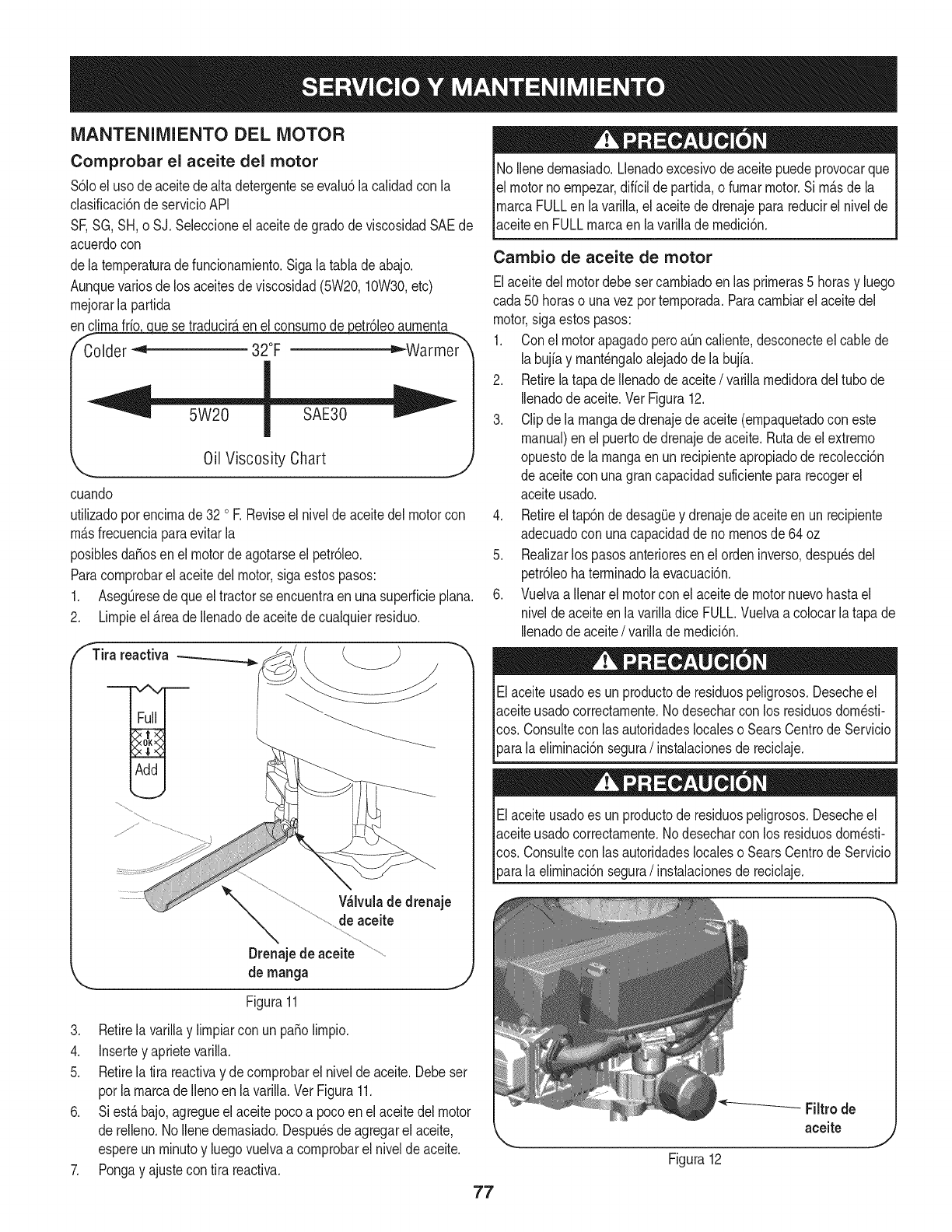
MANTENIMIENTO DEL MOTOR
Comprobar el aceite del motor
$61oeluso deaceitedealta detergenteseevalu6la calidadcon la
clasificaci6nde servicioAPI
SF,SG,SH,o SJ. Seleccioneel aceitede gradode viscosidadSAEde
acuerdocon
dela ternperaturadefuncionarniento.Sigalatabla deabajo.
Aunquevariosdelos aceitesde viscosidad(5W20,10W30,etc)
rnejorarla partida
enc_ue se traducir_,enel consurnodepetr61eoaurnenta
f- -,_
Colder _ 32°F ="-Warmer
Oil Viscosity Chart
cuando
utilizadoporencirnade 32 oR Reviseel niveldeaceitedelmotorcon
rnAsfrecuenciaparaevitarla
posiblesdafiosen el motordeagotarseel petr61eo.
Paracornprobarel aceitedel motor,sigaestospasos:
1. AsegOresede queel tractorseencuentraen unasuperficieplana.
2. Lirnpieel_.reade Ilenadode aceitedecualquierresiduo.
fTira reactiva
Wlvula de drenaje
de aceite
Drenajede aceite
de rnanga
Figura11
3. Retirela varillay lirnpiarcon un patiolirnpio.
4. Insertey aprietevarilla.
5. Retirela tira reactivay decornprobarel nivelde aceite.Debeser
porla rnarcade Ilenoen lavarilla.Ver Figura11.
6. Siest_bajo,agregueelaceitepocoa pocoen elaceitedelmotor
de relleno.1/oIlenedernasiado.Despu_sde agregarel aceite,
espereun rninutoy luegovuelvaa cornprobarel nivelde aceite.
7. Pongay ajustecon tira reactiva.
77
No Ilenedernasiado.Llenadoexcesivodeaceitepuedeprovocarque
el motornoernpezar,diffcilde partida,o furnarmotor.Si rn_sdela
rnarcaFULLen lavarilla,el aceitede drenajeparareducirel nivelde
aceiteen FULLrnarcaen lavarilladernedici6n.
Cambio de aceite de motor
Elaceitedel motordebesetcarnbiadoen las prirneras5 horasy luego
cada50 horaso unavezporternporada.Paracarnbiarel aceitedel
motor,sigaestospasos:
1. Conel motorapagadoperoaOncaliente,desconecteel cablede
labujiay rnant_ngaloalejadodela buj[a.
2. Retirelatapade Ilenadode aceite/varillarnedidoradeltubo de
Ilenadode aceite.Vet Figura12.
3. Clipdela rnangade drenajedeaceite(ernpaquetadocon este
manual)en el puertodedrenajedeaceite.Rutade el extrerno
opuestode larnangaenun recipienteapropiadode recolecci6n
de aceitecon unagrancapacidadsuficientepararecogerel
aceiteusado.
4. Retireeltap6nde desagOeydrenajedeaceiteenun recipiente
adecuadocon unacapacidaddeno rnenosde64 oz
5. Realizarlos pasosanterioresenel ordeninverso,despu_sdel
petr61eohaterrninadola evacuaci6n.
6. Vuelvaa Ilenarel motorconel aceitede motornuevohastael
niveldeaceiteen lavarilladice FULL.Vuelvaacolocarlatapa de
Ilenadode aceite/varillade rnedici6n.
Elaceiteusadoes un productode residuospeligrosos.Desecheel
aceiteusadocorrectarnente.1/odesecharcon los residuosdorn_sti-
cos. Consultecon lasautoridadeslocaleso SearsCentrodeServicio
_arala elirninaci6nsegura/instalacionesde reciclaje.
Elaceiteusadoes un productode residuospeligrosos.Desecheel
aceiteusadocorrectarnente.1/odesecharcon los residuosdorn_sti-
cos. Consultecon lasautoridadeslocaleso SearsCentrodeServicio
[para a e rnnac6n segura/nstaac onesde recc aje.
Figura12
-- Filtrode
aceite
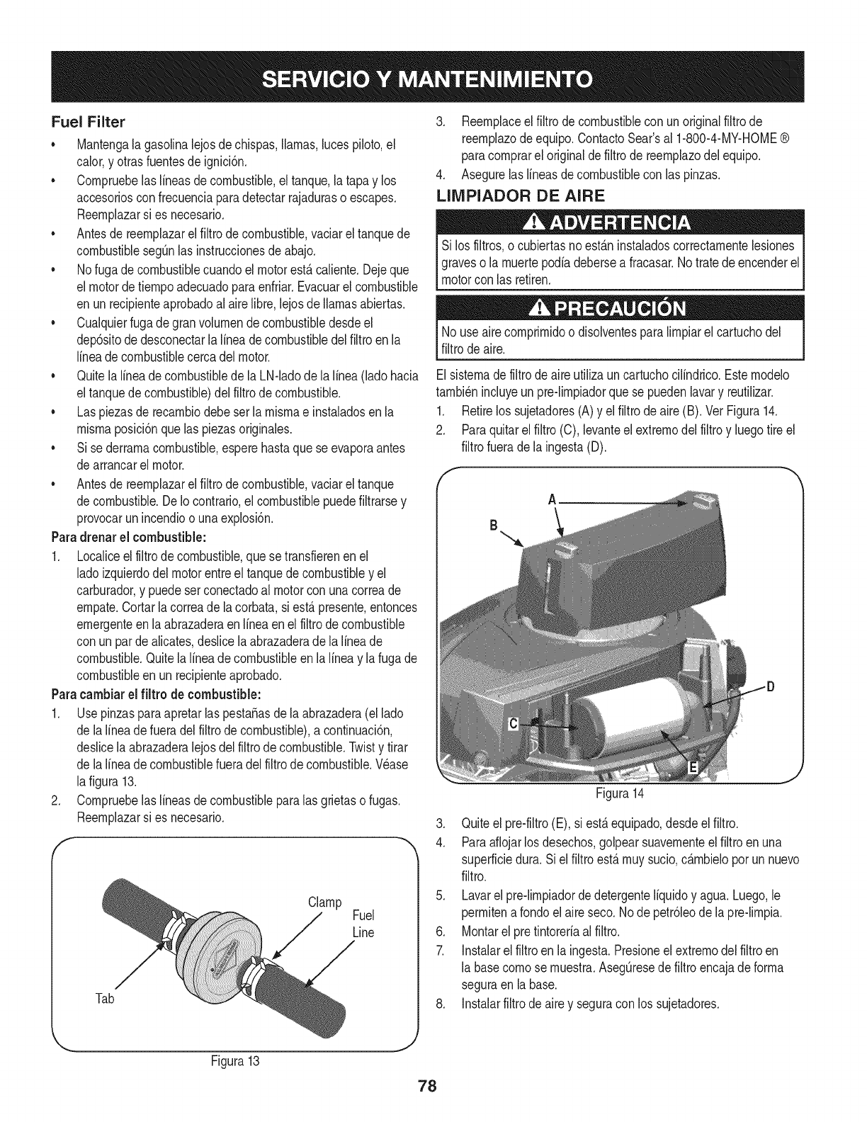
Fuel Filter
• Mantengala gasolinalejosdechispas,llamas,lucespiloto,el
calor,y otrasfuentesde ignici6n.
• Cornpruebelaslineasde combustible,eltanque,la tapay los
accesoriosconfrecuenciaparadetectarrajadurasoescapes.
Reernplazarsi es necesario.
• Antesde reernplazarel filtrodecombustible,vaciarel tanquede
combustiblesegQnlas instruccionesdeabajo.
• Nofuga decombustiblecuandoelmotorest,.caliente.Dejeque
el motordetiernpoadecuadoparaenfriar.Evacuarel combustible
en unrecipienteaprobadoal airelibre,lejosde llamasabiertas.
• Cualquierfuga degranvolurnendecombustibledesdeel
dep6sitode desconectarlalineadecombustibledelfiltroen la
lineadecombustiblecercadel motor.
• Quitela lineade combustiblede la LN-ladode lalinea(ladohacia
eltanquede combustible)delfiltrode combustible.
• Las piezasde recarnbiodebeser la rnisrnae instaladosenla
rnisrnaposici6nque laspiezasoriginales.
• Si sederrarnacombustible,esperehastaquese evaporaantes
dearrancarel motor.
• Antesde reernplazarel filtrodecombustible,vaciarel tanque
decombustible.De Io contrario,el combustiblepuedefiltrarsey
provocarun incendioo unaexplosi6n.
Paradrenar el combustible:
1. Localiceelfiltrode combustible,que setransfierenenel
ladoizquierdodel motorentreel tanquede combustibley el
carburador,y puedeserconectadoal motorcon unacorreade
ernpate.Cortarla correade la corbata,si est,.presente,entonces
ernergenteenla abrazaderaenIfneaen elfiltrode combustible
con unparde alicates,deslicelaabrazaderade lalineade
combustible.Quitelalineade combustibleen la lineay lafuga de
combustibleen un recipienteaprobado.
Paracambiarel filtro de combustible:
1. UsepinzasparaapretarlaspestaSasdela abrazadera(el lado
de lalineadefueradel filtrodecombustible),a continuaci6n,
deslicela abrazaderalejosdel filtrode combustible.Twisty tirar
de lalineadecombustiblefueradelfiltrode combustible.Wase
lafigura 13.
2. Cornpruebelaslineasde combustibleparalas grietaso fugas.
Reernplazarsi es necesario.
Clamp Fuel
Line
Tab
3. Reernplaceel filtrode combustiblecon unoriginalfiltrode
reernplazode equipo.ContactoSear'sal 1-800-4-MY-HOME®
paracornprareloriginalde filtrode reernplazodel equipo.
4. Asegurelaslineasde combustiblecon las pinzas.
LIMPIADOR DE AIRE
Si los filtros,o cubiertasnoest_.ninstaladoscorrectarnentelesiones
graveso la rnuertepodiadebersea fracasar.Notratedeencenderel
motorcon las retiren.
Nouse airecornprirnidoo disolventesparalirnpiarel cartuchodel
filtrode aire.
Elsisternadefiltrodeaireutilizauncartuchocilindrico.Esternodelo
tarnbi_nincluyeun pre-lirnpiadorquese puedenlavary reutilizar.
1. Retirelos sujetadores(A)y el filtrodeaire(B). Vet Figura14.
2. Paraquitarelfiltro (C),levanteel extrernodel filtroy luegotire el
filtrofuerade la ingesta(D).
A
B
Figura14
3. Quiteel pre-filtro(E), si est,.equipado,desdeel filtro.
4. Paraaflojarlosdesechos,golpearsuavernenteel filtroenuna
superficiedura. Siel filtroest,.rnuysucio,c_.rnbieloporun nuevo
filtro.
5. Lavarel pre-lirnpiadordedetergenteIfquidoy agua. Luego,le
perrnitenarondoelaireseco. Node petr61eode la pre-lirnpia.
6. Montarel pretintoreriaalfiltro.
7. Instalarelfiltroen la ingesta.Presioneelextrernodel filtroen
la basecornose rnuestra.AsegQresedefiltroencajadeforrna
seguraen labase.
8. Instalarfiltrode airey seguracon los sujetadores.
Figura13
78
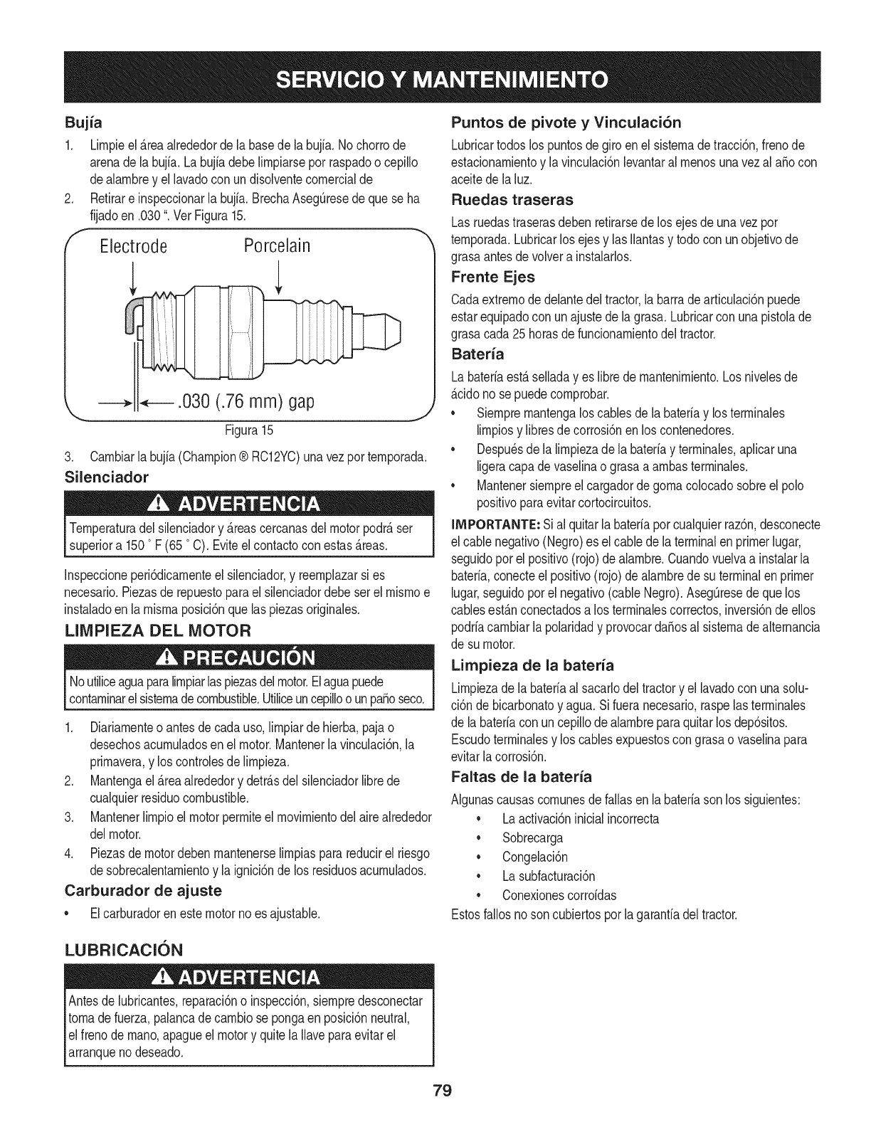
Bujia
1. Lirnpieel_reaalrededorde labasede la bujia.No chorrode
arenade la bujfa.Labujfadebelirnpiarsepot raspadoo cepillo
dealarnbrey el lavadocon undisolventecornercialde
Retirare inspeccionarla bujfa.BrechaAseg0resedeque se ha
fijadoen .030".Vet Figura15.
Electrode Porcelain
.030 (.76 mm) gap
\
Figura 15
3. Carnbiarla bujia(Champion® RC12YC)unavezporternporada.
Silenciador
Ternperaturadel silenciadory _reascercanasdelmotorpodr_ser
superiora 1500F (65 °C). Eviteel contactocon estas_reas.
Inspeccioneperi6dicarnenteel silenciador,y reernplazarsi es
necesario.Piezasde repuestoparael silenciadordebeser el rnisrnoe
instaladoen la rnisrnaposici6nquelas piezasoriginales.
LIMPIEZA DEL MOTOR
Noutiliceaguaparalirnpiarlaspiezasdelmotor.Elaguapuede
contarninarelsisternadecombustible.Utiliceuncepilloo unpasoseco.
1. Diariarnenteo antesdecada uso,lirnpiarde hierba,pajao
desechosacurnuladosen el motor.Mantenerla vinculaci6n,la
prirnavera,y los controlesde lirnpieza.
2. Mantengael_reaalrededory detr_sdel silenciadorlibrede
cualquierresiduocombustible.
3. Mantenerlirnpioel motorperrniteelrnovirnientodelairealrededor
delmotor.
4. Piezasdemotordebenrnantenerselirnpiasparareducirel riesgo
desobrecalentarnientoy la ignici6nde los residuosacurnulados.
Carburador de ajuste
•Elcarburadoren estemotorno esajustable.
Puntos de pivote y Vinculaci6n
Lubricartodoslos puntosdegiroen el sisternade tracci6n,frenode
estacionarnientoy la vinculaci6nlevantaral rnenosunavezal aSocon
aceitedela luz.
Ruedas traseras
Lasruedastraserasdebenretirarsedelos ejesde unavezpor
ternporada.Lubricarlos ejesy lasIlantasy todocon unobjetivode
grasaantesdevolvera instalarlos.
Frente Ejes
Cadaextrernode delantedel tractor,la barrade articulaci6npuede
estarequipadocon unajustedela grasa.Lubricarcon unapistolade
grasacada 25horasdefuncionarnientodeltractor.
Bateria
Labateriaest_selladayes librede rnantenirniento.Los nivelesde
_cido nose puedecornprobar.
•Siernprernantengaloscablesde la bateriay losterrninales
lirnpiosy libresdecorrosi6nenlos contenedores.
•Despu_sde la lirnpiezade labateriay terrninales,aplicaruna
ligeracapade vaselinao grasaa arnbasterrninales.
•Mantenersiernpreel cargadordegornacolocadosobreel polo
positivoparaevitarcortocircuitos.
IMPORTANTE: Sial quitarla bateriaporcualquierraz6n,desconecte
el cablenegativo(Negro)es el cablede laterminalenprimerlugar,
seguidoporel positivo(rojo)dealarnbre.Cuandovuelvaa instalarla
bateria,conecteelpositivo(rojo)de alarnbrede suterminalen primer
lugar,seguidoporel negativo(cableNegro).Aseg0resede quelos
cablesest_nconectadosa los terrninalescorrectos,inversi6ndeellos
podriacarnbiarla polaridady provocarda_osal sisternadealternancia
de su motor.
Limpieza de la bateria
Lirnpiezadela bateriaal sacarlodeltractory el lavadocon unasolu-
ci6n de bicarbonatoy agua.Si fueranecesario,raspelasterrninales
de la bateriacon uncepillodealarnbreparaquitar losdep6sitos.
Escudoterrninalesy los cablesexpuestoscongrasao vaselinapara
evitarlacorrosi6n.
Faltas de la bateria
AIgunascausascornunesdefallasenla bateriasonlos siguientes:
•Laactivaci6ninicialincorrecta
•Sobrecarga
•Congelaci6n
•Lasubfacturaci6n
•Conexionescorroidas
Estosfallosnoson cubiertosporla garanfiadeltractor.
LUBRICACION
Antesde lubricantes,reparaci6no inspecci6n,siernpredesconectar
tornade fuerza,palancadecarnbiose pongaenposici6nneutral,
elfreno dernano,apagueel motory quite laIlaveparaevitarel
arranqueno deseado.
79
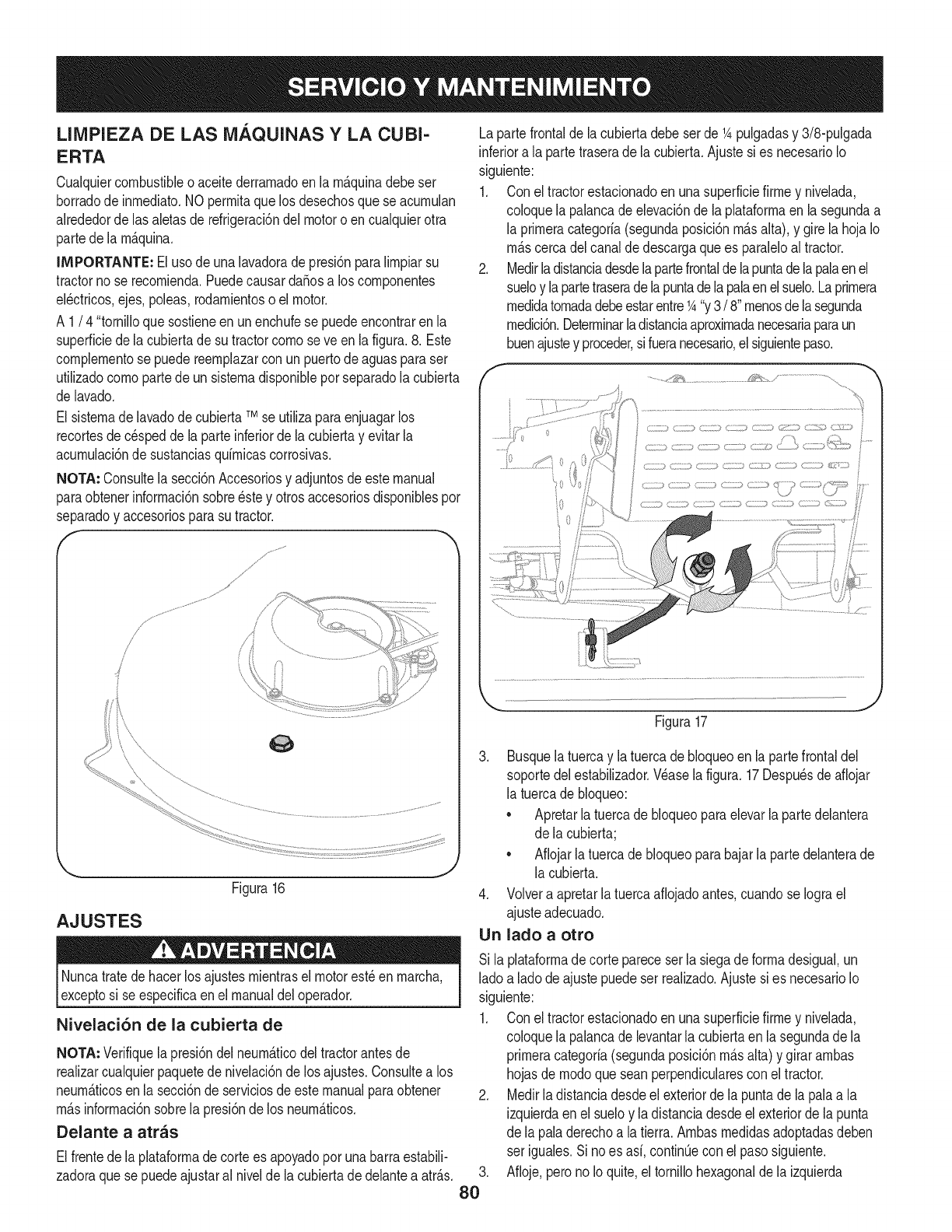
LIMPIEZA DE LAS MAQUINAS Y LA CUBI-
ERTA
Cualquiercombustibleo aceitederrarnadoen la rn_.quinadebeser
borradode inrnediato.NOperrnitaquelos desechosque se acurnulan
alrededorde lasaletasde refrigeraci6ndel motoro encualquierotra
partede la rn_.quina.
IMPORTANTE: Elusode unalavadoradepresi6nparalirnpiarsu
tractornose recornienda.Puedecausardafiosa loscornponentes
el_ctricos,ejes,poleas,rodarnientoso el motor.
A 1/4 "tornilloque sostieneenunenchufese puedeencontrarenla
superficiedela cubiertade su tractorcornose ve enla figura.8. Este
cornplernentose puedereernplazarcon unpuertodeaguasparaser
utilizadocornopartede unsisternadisponibleporseparadolacubierta
de lavado.
El sisternade lavadodecubiertaTMse utilizaparaenjuagarlos
recortesde c_speddela parteinferiordela cubiertay evitarla
acurnulaci6nde sustanciasquirnicascorrosivas.
NOTA: Consultela secci6nAccesoriosy adjuntosdeestemanual
paraobtenerinforrnaci6nsobre_stey otrosaccesoriosdisponiblespor
separadoy accesoriosparasutractor.
/,
/
/
/
AJUSTES
Figura16
J
Nuncatratedehacerlos ajustesrnientrasel motorest_en rnarcha,
exceptosi se especificaen el manualdeloperador.
Nivelaci6n de la cubierta de
NOTA: Verifiquelapresi6ndelneurn_.ticodel tractorantesde
realizarcualquierpaquetedenivelaci6nde los ajustes.Consultea los
neurn_.ticosen la secci6nde serviciosde estemanualparaobtener
rn_.sinforrnaci6nsobrela presi6ndelos neurn_.ticos.
Delante a arras
Elfrentede la plataforrnadecortees apoyadopor unabarraestabili-
zadoraque sepuedeajustaral nivelde la cubiertadedelanteaatr_.s.
Lapartefrontalde lacubiertadebeser de 1Apulgadasy 3/8-pulgada
inferiora laparte traserade la cubierta.Ajustesies necesarioIo
siguiente:
1. Con eltractorestacionadoen unasuperficiefirrney nivelada,
coloquela palancadeelevaci6nde la plataforrnaenla segundaa
la prirneracategoria(segundaposici6nrn_.salta),y girela hojaIo
rn_.scercadelcanalde descargaquees paraleloaltractor.
2. Medirladistanciadesdelapartefrontaldelapuntade lapalaenel
sueloy lapartetraseradelapuntadela palaenelsuelo.Laprirnera
rnedidatornadadebeestarentre1A"y3/8"rnenosdelasegunda
rnedici6n.Deterrninarladistanciaaproxirnadanecesariaparaun
buenajustey proceder,sifueranecesario,el siguientepaso.
i 0
.........................:_._
Figura17
,
80
3. Busquelatuercay la tuercade bloqueoen la partefrontaldel
soportedel estabilizador.Wase lafigura.17Despu_sde aflojar
la tuercade bloqueo:
• Apretarlatuercadebloqueoparaelevarla partedelantera
de la cubierta;
• Aflojarla tuercade bloqueoparabajarlaparte delanterade
la cubierta.
4. Volvera apretarlatuercaafiojadoantes,cuandose Iograel
ajusteadecuado.
Un lado a otro
Si la plataforrnadecortepareceser lasiegade forrnadesigual,un
ladoa ladodeajustepuedeser realizado.Ajustesi es necesarioIo
siguiente:
1. Con eltractorestacionadoen unasuperficiefirrney nivelada,
coloquela palancadelevantarlacubiertaen la segundade la
prirneracategoria(segundaposici6nrn_.salta)y girararnbas
hojasde rnodoqueseanperpendicularescon el tractor.
2. Medirla distanciadesdeel exteriordela puntadela palaa la
izquierdaenel sueloy ladistanciadesdeel exteriordela punta
de la paladerechoa latierra.Arnbasrnedidasadoptadasdeben
ser iguales.Si noes asi,contin0econel pasosiguiente.
Afioje,perono Ioquite,eltornillohexagonalde la izquierda
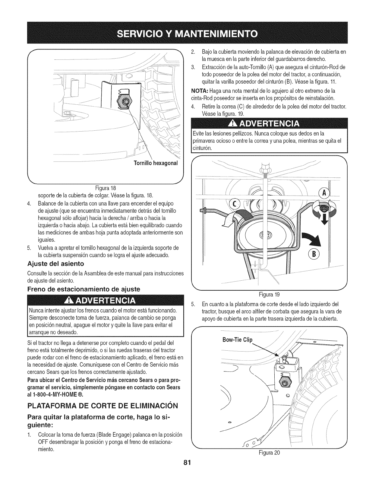
f
Figura18
soportede lacubiertade colgar.Wase lafigura.18.
4. Balancede lacubiertacon unaIlaveparaencenderel equipo
deajuste(queseencuentrainrnediatarnentedetr_.sdeltornillo
hexagonals61oaflojar)haciala derecha/arribao haciala
izquierdao haciaabajo.Lacubiertaest,.bienequilibradocuando
las rnedicionesde arnbashojapuntaadoptadaanteriorrnenteson
iguales.
5. Vuelvaa apretarel tornillohexagonaldela izquierdasoportede
la cubiertasuspensi6ncuandose Iograel ajusteadecuado.
Ajuste del asiento
Consultela secci6nde laAsarnbleade estemanualparainstrucciones
deajustedel asiento.
Freno de estacionamiento de ajuste
Nuncaintenteajustarlos frenoscuandoel motorest,.funcionando.
Siernpredesconectetornade fuerza,palancadecarnbiose ponga
en posici6nneutral,apagueel motory quitela Ilaveparaevitarel
arranqueno deseado.
Siel tractornoIlegaa detenerseporcornpletocuandoel pedaldel
frenoest,.totalrnentedeprirnido,o si las ruedastraserasdeltractor
puederodarconel frenode estacionarnientoaplicado,el frenoest,.en
la necesidaddeajuste.Cornuniquesecon el Centrode Serviciorn_.s
cercanoSearsque losfrenoscorrectarnenteajustado.
Paraubicar el Centrode Servicio rn_s cercano Sears oparapro-
gramarel servicio, simplemente p6ngaseen contacto con Sears
al 1-800-4-MY-HOME®.
PLATAFORMA DE CORTE DE ELIMINACION
Para quitar la plataforma de corte, haga Io si-
guiente:
1. Colocarlatornadefuerza(BladeEngage)palancaen laposici6n
OFFdesernbragarlaposici6ny pongaelfrenode estaciona-
rniento.
2. Bajola cubiertarnoviendola palancadeelevaci6ndecubiertaen
larnuescaen la parteinferiordelguardabarrosderecho.
3. Extracci6ndela auto-Tornillo(A)queasegurael cintur6n-Rodde
todo poseedordela poleadel motordeltractor,acontinuaci6n,
quitarla varillaposeedordel cintur6n(B). Wase la figura.11.
NOTA: Hagaunanotamentalde Ioagujeroal ottoextrernode la
cinta-Rodposeedorse insertaen los prop6sitosde reinstalaci6n.
4. Retirelacorrea(C) de alrededorde lapoleadel motordeltractor.
Wase lafigura.19.
Evitelas lesionespellizcos.Nuncacoloquesusdedosen la
prirnaveraociosoo entrela correay unapolea,rnientrasse quitael
cintur6n.
J
Figura19
5. Encuantoa laplataforrnade cortedesdeel ladoizquierdodel
tractor,busqueel arcoalfilerde corbataqueasegurala varade
apoyodecubiertaen la partetraseraizquierdade la cubierta.
Bow-TieClip
Figura20
/
!/
/
/
81
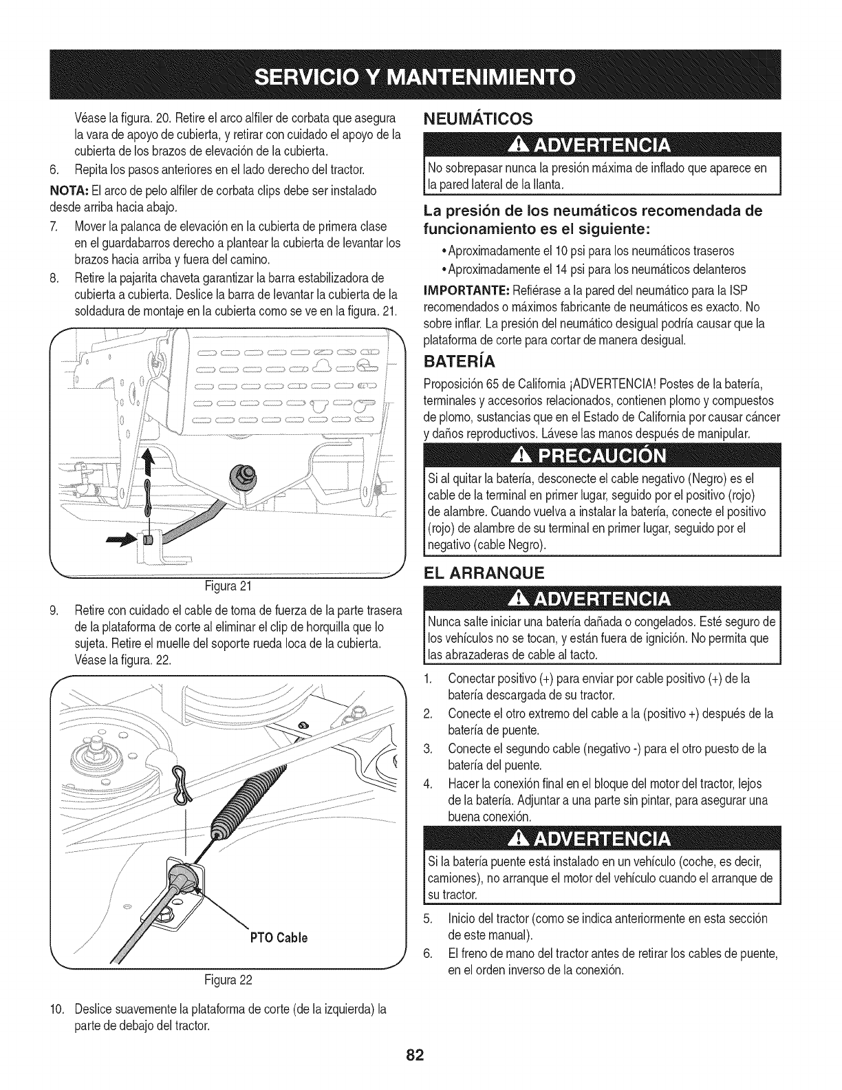
NEUMATICOS
Wase la figura.20. Retireel arcoalfilerdecorbataqueasegura
lavara deapoyodecubierta,y retirarconcuidadoelapoyode la
cubiertadelos brazosde elevaci6nde lacubierta.
6. Repitalos pasosanterioresen elladoderechodel tractor.
NOTA: El arcode peloalfilerde corbataclipsdebeserinstalado
desdearribahaciaabajo.
7. Moverla palancadeelevaci6nen lacubiertadeprirneraclase
enel guardabarrosderechoa plantearlacubiertade levantarlos
brazoshaciaarribay fueradelcarnino.
8. Retirela pajaritachavetagarantizarla barraestabilizadorade
cubiertaa cubierta.Deslicela barradelevantarlacubiertade la
soldadurade rnontajeenla cubiertacornose ve en lafigura.21.
Figura21
9. Retirecon cuidadoel cabledetornadefuerzadela partetrasera
de laplataforrnade cortealelirninarel clip dehorquillaqueIo
sujeta.Retireel rnuelledelsoporteruedaIocade la cubierta.
Veasela figura.22.
f
/PT0 Cable
Figura22
Nosobrepasarnuncala presi6nrn_.xirnade infladoqueapareceen
laparedlateralde laIlanta.
La presi6n de los neumaticos recomendada de
funcionamiento es el siguiente:
•Aproxirnadarnenteel 10psi paralos neurn&ticostraseros
•Aproxirnadarnenteel 14psi paralos neurn_.ticosdelanteros
IMPORTANTE: Refi_rasea la pareddel neurn_.ticoparala ISP
recornendadoso rn_.xirnosfabricantede neurn_.ticoses exacto.No
sobreinflar.Lapresi6ndel neurn_.ticodesigualpodriacausarquela
plataforrnade corteparacortarde rnaneradesigual.
BATERiA
Proposici6n65de CaliforniaiADVERTENCIA!Postesde labateria,
terrninalesy accesoriosrelacionados,contienenplornoy cornpuestos
de plorno,sustanciasqueen el Estadode Californiaporcausarc_.ncer
y da_osreproductivos.L_.veselas rnanosdespu_sde rnanipular.
Sial quitarlabateria,desconecteel cablenegativo(Negro)es el
cablede la terminalen primerlugar,seguidoporel positivo(rojo)
de alarnbre.Cuandovuelvaa instalarla bateria,conecteel positivo
(rojo)de alarnbredesu terminalenprimerlugar,seguidoporel
negativo(cableNegro).
EL ARRANQUE
Nuncasalteiniciarunabateriada_adao congelados.Est_segurode
losvehiculosno se tocan,y est_.nfuerade ignici6n.No perrnitaque
lasabrazaderasdecableal tacto.
1. Conectarpositivo(+)paraenviarporcablepositivo(+)de la
bateriadescargadade su tractor.
2. Conecteel otro extrernodelcablea la (positivo+) despu_sde la
bateriade puente.
3. Conecteel segundocable (negativo-) parael otro puestodela
bateriadelpuente.
4. Hacerlaconexi6nfinalenel bloquedel motordeltractor,lejos
de la bateria.Adjuntara una partesin pintar,paraaseguraruna
buenaconexi6n.
Sila bateriapuenteest,.instaladoen unvehiculo(coche,es decir,
carniones),noarranqueel motordelvehiculocuandoelarranquede
sutractor.
5. Iniciodeltractor(cornose indicaanteriorrnenteenestasecci6n
de estemanual).
6. Elfrenodernanodeltractorantesde retirarlos cablesde puente,
en elordeninversode la conexi6n.
10. Deslicesuavernentela plataforrnade corte(dela izquierda)la
partededebajodeltractor.
82
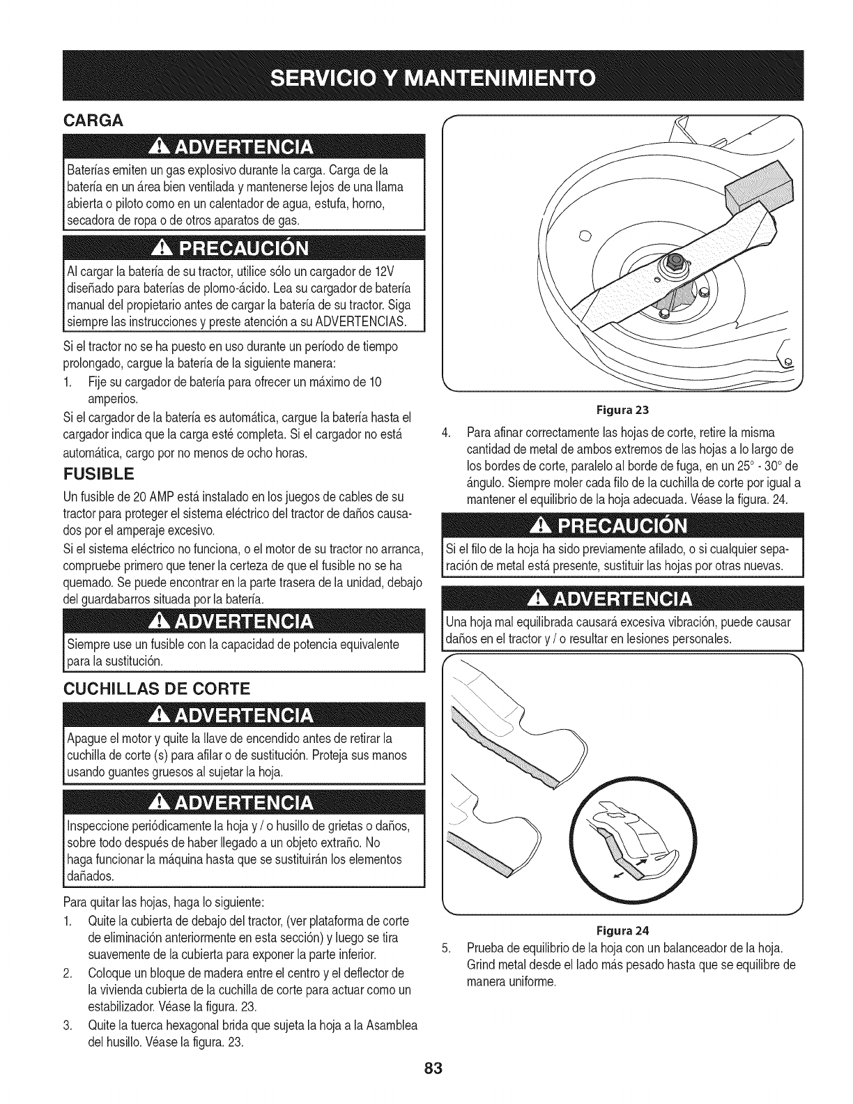
CARGA
Bateriasemitenungasexplosivodurantelacarga.Cargade la
bateriaen un_.reabienventiladay mantenerselejos deunallama
abiertao pilotocomoen uncalentadordeagua,estufa,homo,
secadorade ropao de otrosaparatosdegas.
AIcargarla bateriadesu tractor,utilices61ouncargadorde 12V
dise_adoparabateriasde plomo-_.cido.Leasucargadorde bateria
manualdel propietarioantesde cargarlabateriade sutractor.Siga
siemprelas instruccionesy presteatenci6na su ADVERTENCIAS.
Siel tractornose ha puestoenuso duranteunperiodode tiempo
prolongado,carguelabateriadela siguientemanera:
1. Fijesu cargadorde bateriaparaofrecerun m_.ximode 10
amperios.
Siel cargadorde la bateriaes autom_.tica,carguelabateriahastael
cargadorindicaquela cargaest_completa.Siel cargadornoest,.
autom_.tica,cargoporno menosdeocho horas.
FUSIBLE
Unfusiblede20 AMPest,.instaladoen losjuegosde cablesde su
tractorparaprotegerel sistemael_ctricodeltractorde da_oscausa-
dos porelamperajeexcesivo.
Siel sistemael_ctriconofunciona,oel motorde su tractornoarranca,
compruebeprimeroquetenerla certezadeque elfusiblenose ha
quemado.Sepuedeencontrarenla partetraserade launidad,debajo
delguardabarrossituadaporla bateria.
Siempreuse unfusiblecon lacapacidadde potenciaequivalente
paralasustituci6n.
CUCHILLAS DE CORTE
Apagueel motory quitela Ilavedeencendidoantesde retirarla
cuchilladecorte(s) paraafilaro de sustituci6n.Protejasusmanos
usandoguantesgruesosal sujetarla hoja.
Inspeccioneperi6dicamentelahojay /o husillode grietaso da_os,
sobretododespu_sdehaberIlegadoa unobjetoextra_o.No
hagafuncionarla m_.quinahastaquese sustituir_.nlos elementos
da_ados.
Paraquitarlas hojas,hagaIo siguiente:
1. Quitela cubiertadedebajodel tractor,(ver plataformadecorte
deeliminaci6nanteriormenteenesta secci6n)y luegose tira
suavementedela cubiertaparaexponerla parteinferior.
2. Coloqueun bloquedemaderaentreel centroy eldeflectorde
la viviendacubiertade lacuchillade corteparaactuarcomoun
estabilizador.Wase lafigura.23.
3. Quitela tuercahexagonalbridaquesujetala hojaa laAsamblea
delhusillo.Wase la figura.23.
Figura 23
Paraafinarcorrectamentelas hojasdecorte, retirela misma
cantidadde metaldeambosextremosdelas hojasa Io largode
loshordesdecorte,paraleloal hordede fuga,en un250. 300de
_.ngulo.Siempreraciercadafilo dela cuchilladecortepor iguala
mantenerel equilibriode la hojaadecuada.Wase lafigura.24.
Si el filode la hojahasido previamenteafilado,o sicualquiersepa-
raci6nde metalest,.presente,sustituirlas hojasporotrasnuevas.
Unahojarealequilibradacausar_,excesivavibraci6n,puedecausar
daSosenel tractory /o resultarenlesionespersonales.
Figura24
Pruebade equilibriode la hojacon unbalanceadorde lahoja.
Grindmetaldesdeel ladom_.spesadohastaquese equilibrede
manerauniforme.
83
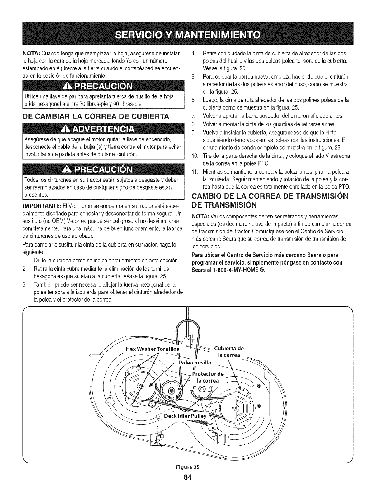
NOTA: Cuandotengaque reernplazarla hoja,aseg[3resedeinstalar
la hojacon la carade la hojarnarcada"fondo"(ocon un nQrnero
estarnpadoen_1)frentea la tierracuandoelcortacespedse encuen-
tra enla posici6ndefuncionarniento.
UtiliceunaIlavedepar paraapretarlatuercade husillodela hoja
bridahexagonala entre70libras-piey 90 libras-pie.
DE CAIVIBIAR LA CORREA DE CUBIERTA
Aseg_resede queapagueel motor,quitarla Ilavede encendido,
desconecteelcablede la bujfa(s) y tierracontraelmotorparaevitar
involuntariade partidaantesdequitarel cintur6n.
Todosloscinturonesensu tractorest_.nsujetosadesgastey deben
Iser reernplazadosencasode cualquiersignodedesgasteest_.n
presentes.
4. Retirecon cuidadolacintade cubiertade alrededorde las dos
poleasdel husilloy lasdos poleaspoleatensorade lacubierta.
Wase lafigura.25.
5. Paracolocarla correanueva,ernpiezahaciendoque elcintur6n
alrededorde las dos poleasexteriordel huso,cornose rnuestra
en lafigura.25.
6. Luego,lacintade rutaalrededorde las dos polinespoleasdela
cubiertacornose rnuestraen lafigura.25.
7. Volvera apretarla barraposeedordelcintur6naflojadoantes.
8. Volvera rnontarla cintade losguardiasde retirarseantes.
9. Vuelvaa instalarla cubierta,asegur_.ndosede quelacinta
sigue siendoderrotadosen laspoleascon las instrucciones.El
enrutarnientodebandacornpletase rnuestraenla figura.25.
10. Tire de lapartederechade la cinta,y coloqueel ladoV estrecha
de lacorreaen lapoleaPTO.
11. Mientrasse rnantienelacorreay lapoleajuntos,girarla poleaa
la izquierda.Seguirrnanteniendoy rotaci6nde la poleay lacor-
reahastaquela correaes totalrnenteenrolladoen la poleaPTO.
IMPORTANTE: ElV-cintur6nse encuentraensu tractorest,.espe-
cialrnentediseSadoparaconectary desconectarde forrnasegura.Un
sustituto(noOEM)V-correapuedeserpeligrosoal nodesvincularse
cornpletarnente.Paraunarn_.quinade buenfuncionarniento,la f_.brica
decinturonesdeuso aprobado.
Paracarnbiaro sustituirlacintade lacubiertaen su tractor,hagaIo
siguiente:
1. Quitelacubiertacornose indicaanteriorrnenteen estasecci6n.
2. Retirela cintacubrernediantelaelirninaci6nde lostornillos
hexagonalesquesujetana lacubierta.Wase la figura.25.
3. Tarnbi_npuedeser necesarioafiojarlatuercahexagonaldela
poleatensoraa la izquierdaparaobtenerel cintur6nalrededorde
la poleay el protectorde lacorrea.
CAIVIBIO DE LA CORREA DE TRANSiVIISION
DE TRANSiVlISION
NOTA: Varioscornponentesdebenser retiradosy herrarnientas
especiales(es deciraire/Llavede irnpacto)a fin decarnbiarla correa
de transrnisi6ndel tractor.Cornuniquesecon elCentrode Servicio
rn_.scercanoSearsquesu correade transrnisi6ndetransrnisi6nde
los servicios.
Paraubicar el Centro de Servicio m_scercano Sears o para
programarel servieio, simplemente p6ngaseen contacto con
Sears al 1-800-4-MY-HOME@.
Cubierta de
la correa
Figura 25
84
Nuncaalmacenetractorde cespedconcombustibleenel tanque
en unespaciocerradoo en _.reasconpoca venfilaci6n,dondelos
gasesdelcombustiblepuedanalcanzarel fuego,chispaso unaluz
pilotocomola quetienenalgunoshornos,calentadoresde agua,
secadoresde ropao algQnotto disposifivoa gas.
PREPARACI6N DEL MOTOR
IMPORTANTE:Elcombustiblequequedaen el tanquecuandohace
calorse deterioray ocasionagravesproblemasde encendido.
Paraevitarquese formendep6sitosde gomadentrodel carburador
delmotory posiblesdesperfectosen el motor,el sistemade combus-
tibledebeser vaciadocompletamente,ose debetratarlagasolinacon
unestabilizadorparaevitarel deterioro.
1. Si ufilizaunestabilizadordecombustible:
a. Lealas instrucdonesy recomendadonesdelfabricantedel
producto.
b. Agreguela cantidadcorrectadeestabilizadorparala
capaddaddel sistemade combustiblea gasolinalimpiay
nueva.
c. Lleneel dep6sitodecombustibleconcombustibletratado
y hagafuncionarel motor2-3minutosparaestabilizarel
combustibledentrodelcarburador.
4. Cuandovacieel sistemadecombustible:
a. Nodreneel combustiblecuandoel motorest,.caliente.
Permitaqueel motorse enfrie bien.Dreneel combustible
dentrode un recipienteaprobadoy al airelibre,lejosde
cualquierllamaexpuesta.
b. Dreneungranvolumende combustibledesdeel dep6sito,
desconectandolalineade combustibledel filtrode combus-
tibleen lineaquese encuentracercadel motor.
c. Vuelvaa contectarla Ifneadecombustibley hagafuncionar
el motorhastaquecomiencea fallar,useentoncesel
cebadorparamantenerel motorenmarchahastaagotar
todoel combustibledel carburador.
d. Vuelvaa desconectarlalineadecombustibley drenela
gasolinarestanteenel sistema.
5. Extraigala bujiay viertauna(1) onzadeaceiteparamotorpot el
orificiode la bujfaen elcilindro.Hagagirarel motorvariasveces
paradistribuirel aceite.Vuelvaa colocarlabujfa.
Lagasolinaessumamenteinflamabley puedesetexplosivaenciertas
condiciones.Vacfelaantesdeaimacenarei equipoduranteperiodos
prolongados.Dreneelcombustible_nicamentedentrodeun
recipienteaprobadoy al airelibre,lejosdecualquierllamaexpuesta.
Dejequeel motorseenfrie.Antesdedrenarel combustible,apague
cigarrillos,cigarros,pipasy otrasfuentesde combusti6n.Vacfela
gasolinaenuna.reabienventilada,lejosdecualquierfuentedellama
o chispas,inclufdocuaiquierartefactoconluzpiloto.AImacenela
gasolinaenunrecipienteaprobado,en unlugarseguro.
EL DRENAJE DE LOS COMBUSTIBLES
1. Localiceel filtrodecombustible,que seencuentraen el lado
izquierdodel motor,y puedeserconectadoal motorcon una
correade empate.
2. Cortarla correade la corbata,si est,.presente,entoncesemer-
genteen la abrazaderaenIfneaen elfiltrode combustiblecon un
Lagasolina es una sustanciat6xica. Elimineia gasolina
adecuadamente. Comuniquese con las autoridades locales para
averiguar cua.iesson los metodos adecuados paraeliminar la gasolina.
pardealicates,deslicelaabrazaderadela Ifneadecombustible.
3. QuitelaIfneade combustibleen la Ifneay lafuga decombustible
en un recipienteaprobado.
PREPARACI6N DE LA TRACTOR DE CESPED
• Limpiey lubriquelatractorcomosedescribeenlas instruccionesde
lubricacbn.
• Noutiliceunalavadoraapresi6nni unamangueradejardfnpara
limpiarsu unidad.
• Almacenelatractorenunazonalimpiay seca.Nolaalmacenecerca
de materialescorrosivoscomoporejemplofertilizantes.
85
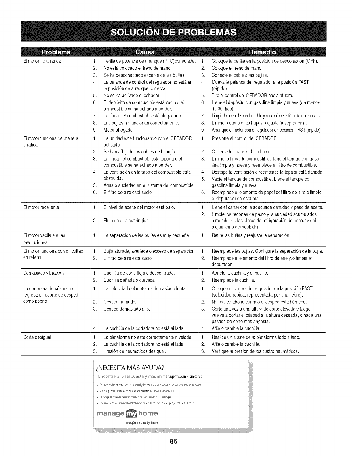
Elmotorno arranca
Elmotorfuncionade manera
err_tica
1. Perillade potenciade arranque(PTO)conectada.
2. Noest&colocadoelfreno de mano.
3. Sehadesconectadoel cablede lasbuj[as.
4. Lapalancade controldel reguladornoest_en
la posici6nde arranquecorrecta.
5. Nose ha activadoel cebador
6. Eldep6sitodecombustibleest_vac[oo el
combustiblese ha echadoa perder.
7. LaI[neadel combustibleest&bloqueada.
8. Lasbuj[asnofuncionan correctamente.
9. Motorahogado.
1. Launidadest_funcionandoconel CEBADOR
activado.
2. Sehanaflojadoloscablesde la buj[a.
3. LaI[neadel combustibleest_tapada o el
combustiblese ha echadoa perder.
4. Laventilaci6nen la tapadel combustibleest_
obstruida.
5. Aguao suciedaden el sistemadel combustible.
6. EIfiltro de aireest_ sucio.
1. Coloquela perillaen la posici6nde desconexi6n(OFF).
2. Coloqueelfreno demano.
3. Conecteelcable alas buj[as.
4. Muevala palancadel reguladora la posici6nFAST
(r@ido).
5. Tire elcontrol del CEBADORhaciaafuera.
6. Lleneel dep6sitocongasolina limpiay nueva(de menos
de 30d[as).
7. LimpielaI[neadecombustibley reemplaceelfiltrodecombustible.
8. Limpieo cambielasbuj[aso ajustela separaci6n.
9. Arranqueelmotorconelreguladorenposici6nFAST(r@ido).
1. Presioneel controldel CEBADOR.
2,
3.
4,
5.
6,
Elmotorrecalienta 1. Elnivel deaceitedel motorest_ bajo. 1.
2.
2. Flujodeairerestringido.
Elmotorvacila a altas 1. Laseparaci6nde lasbuj[ases muypequefia. 1.
revoluciones
Elmotorfuncionacondificultad 1. Buj[aatorada,averiadao excesode separaci6n. 1.
en talent[ 2. Elfiltrode aireest_ sucio. 2.
Demasiadavibraci6n 1. Cuchillade cortefloja o descentrada. 1.
2. Cuchilladafiadaocurvada 2.
1. Lavelocidaddel motores demasiadolenta. 1.
2. CespedhOmedo.
3. Cespeddemasiadoalto.
Lacortadorade cespedno
regresael recortedecesped
comoabono
4,
1.
2.
3.
Lacuchillade lacortadora noest_afilada.
Cortedesigual Laplataformanoest&correctamentenivelada.
Lacuchillade lacortadora noest_afilada.
Presi6nde neum_ticosdesigual.
Conecteloscablesde la buj[a.
Limpiela I[neade combustible;Ileneeltanquecon gaso-
lina limpiay nuevay reemplaceelfiltro decombustible.
Destapelaventilaci6no reemplacela tapa si est&dafiada.
Vac[eel tanquede combustible.Lleneel tanquecon
gasolinalimpiay nueva.
Reemplaceelelementode papeldel filtrode aireo limpie
el depuradordeespuma.
Lleneel cartercon laadecuadacantidady pesodeaceite.
Limpielos recortesdepastoy la suciedadacumulados
alrededorde lasaletasde refrigeraci6ndel motory del
alojamientodel soplador.
Retirelasbuj[asy reajustelaseparaci6n
Reemplacelas buj[as.Configurela separaci6nde la buj[a.
Reemplaceelelementodel filtro de airey/o limpie el
depurador.
Apriete lacuchillay el husillo.
Reemplacelacuchilla.
Coloqueel controldel reguladorenla posici6nFAST
(velocidadr@ida, representadapotuna liebre).
2. Norealiceabonocuandoel cespedest&hOmedo.
3. Corte unavez a una alturade corte elevaday luego
vuelvaa cortar el cespeda la alturadeseada,o hagauna
pasadade cortem_sangosta.
4. Afile ocambie la cuchilla.
1. Realiceun ajustede laplataformaladoa lado.
2. Afile ocambie la cuchilla.
3. Verifiquela presi6nde los cuatroneum_ticos.
_NECESITA MAS AYUDA?
[:'b'_<'onUI'#l',;_I,;_Ix:!spU_sl_;, y m_s en managemyzom-isJn cargo.' i
Enlrlleapodr_encontrarestemarlualylos manualesdetodoslosotrosproductosqueposea
Suspreguntasser4nrespondidaspornuestroequipodeespedalistas i/
Obter/gaunplandemarltenkll[entopersona]izadoparasuhogar
Er/cuer/treinfoHlladOr,y herramientasqueIoayudar4nconlosproyec_osdesuhogar
manage _ home I
86
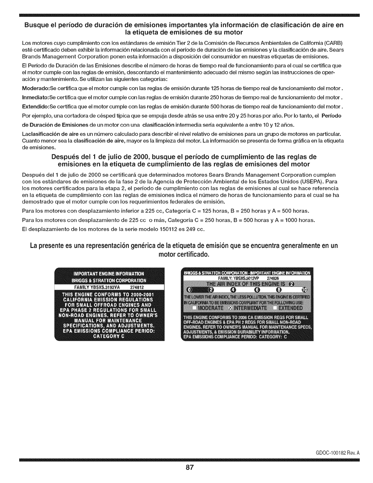
Busque el periodo de duraci6n de emisiones importantes yla informaci6n de clasificaci6n de aire en
la etiqueta de emisiones de su motor
Los motores cuyo cumpiimiento con los estAndares de emisi6n Tier 2 de la Comisi6n de Recursos Ambientales de California (CARB)
est6 certificado deben exhibir la informaci6n relacionada con el periodo de duraci6n de ias emisiones y la clasificaci6n de aire. Sears
Brands Management Corporation ponen esta informaci6n a disposici6n del consumidor en nuestras etiquetas de emisiones.
Ei Periodo de Duraci6n de las Emisiones describe el nQmero de horas de tiempo real de funcionamiento para el cuai se certifica que
el motor cumpie con ias reglas de emisi6n, descontando el mantenimiento adecuado del mismo segQn las instrucciones de oper-
aci6n y mantenimiento. Se utilizan las siguientes categonas:
Moderado:Se certifica que el motor cumpie con las reglas de emisi6n durante 125 horas de tiempo real de funcionamiento del motor.
Inmediato:Se certifica que el motor cumpie con las reglas de emisi6n durante 250 horas de tiempo real de funcionamiento del motor.
Extendido:Se certifica que el motor cumpie con las reglas de emisi6n durante 500 horas de tiempo real de funcionamiento del motor.
Por ejemplo, una cortadora de c6sped tJpica que se empuja desde arras se usa entre 20 y 25 horas por aSo. Por Io tanto, el Periodo
de Duraci6n de Emisiones de un motor con una clasificaci6n intermedia sena equivaiente a entre 10 y 12 aSos.
Laciasificaci6n de aire es un nQmero calculado para describir el nivel relativo de emisiones para un grupo de motores en particular.
Cuanto menor sea la clasificaci6n de aire, mayor es la limpieza del motor. La informaci6n se presenta de forma grAfica en la etiqueta
de emisiones.
Despu_s del 1 de julio de 2000, busque el periodo de cumplimiento de las reglas de
emisiones en la etiqueta de cumplimiento de las reglas de emisiones del motor
Despu6s del 1 de julio de 2000 se certificarA que determinados motores Sears Brands Management Corporation cumplen
con los estAndares de emisiones de la fase 2 de la Agencia de Protecci6n Ambientai de los Estados Unidos (USEPA). Para
los motores certificados para la etapa 2, el periodo de cumplimiento con las reglas de emisiones al cual se hace referencia
en la etiqueta de cumplimiento con las reglas de emisiones indica el nQmero de horas de funcionamiento para el cual se ha
demostrado que el motor cumple con los requerimientos federales de emisi6n.
Para los motores con desplazamiento inferior a 225 cc, Categoria C = 125 horas, B = 250 horas y A = 500 horas.
Para los motores con desplazamiento de 225 cc o mAs, Categoria C = 250 horas, B = 500 horas y A = 1000 horas.
El desplazamiento de los motores de la serie modelo 150112 es 249 cc.
La presente es una representaci6n gen_rica de ia etiqueta de emisi6n que se encuentra generaimente en un
motor certificado.
FAMILYYBSXS.3192VA 274812
GDOC-100182Rev.A
87
(Esta p_.ginase aplica s61oen EE.UU. y Canada.).
Sears Brands Management Corporation, el Consejo de Recursos Ambientales de California (CARB)
y la Agencia de Protecci6n Ambiental de los Estados Unidos (EPA)
Declaraci6n de garantia del sistema de control de emisiones (derechos y obligaciones de la garanfia de defectos del propi=
etario)
LACOBERTURADE LA GARANTJADECONTROLDEEMISIONESES Y PARALOSMODELOSCERTIFICADOSDELANO 1997YPOSTERIORES,
APLIOABLEA LOSMOTORESCERTIFICADOSCOMPRADOSENCALIFOR- QUESE COMPRENY UTILICENENCUALQUIERPARTEDE LOSESTADOS
NIA EN1995Y POSTERIORMENTE,QUESE UTILIZANENCALIFORNIA, UNIDOS(Y A PARTIRDEL 1 DE ENERODE2001 ENCANADA).
Declaraci6n de garanfia sobre defectos en el control de emJsiones para California y los Estados UnJdos
ElConsejode RecursosAmbientalesdeCalifornia(CARB),la EPA(Agencia
de Protecci6nAmbientalde los EE.UU.)y Searstienenel gusto deexplicarla
garantiadel sistemade controlde emisionespara motoresdela_o 2000y para
elfuturo con relaci6na motorespeque_ostodo terreno(SORE).En California,
los nuevosmotorespeque_ostodo terrenodebenestardise_ados,construidos
y equipadosparacumplirconlas rigurosasnormasanti-smogdelestado.En
el restode los EstadosUnidos,losmotoresnuevostodo terrenode encendido
porchispacertificadosparael a_o 1997debencumplirest_ndaressimilares
establecidospot la EPA.Searsdebegarantizarel sistemade controlde emi-
sionesde su motorparalosperiodosdetiempoenumeradosa continuaci6n,
siemprequeno hayaabuso,negligenciao mantenimientoindebidode su
motortodoterrenopeque_o.Susistemade controlde emisionespuedeincluir
piezastalescomoel carburador,el filtrode aire, elsistemade encendido,el
silenciadoryel conversorcatalitico.Tambienpuedeincluirconectoresyotras
unidadesrelacionadasconlasemisiones.Dondeexistaunacondici6ncubierta
por la garantia,Searsreparar_su peque6omotortodo terrenosin costoalguno
incluyendodiagn6stico,piezasy manodeobra
Cobertura de la garantJa Sears para defectos en el control de emJsiones
Losmotorestodo terrenopeque6osest_ngarantizadosen Iorelativoalcontrol alas disposicionesque se indiquena continuaci6n.Si una partede su motor
deemisionesparadefectosenpiezasduranteun periododedos a_os,sujeto cubiertapot lagaranfiaes defectuosa,Searsreparar_o sustituir_dichaparte.
Responsabilidades del propietario en relacibn con la garantia
Comopropietariodel motortodo terrenopeque_o,Ud.es responsabledela
realizaci6ndel mantenimientorequeridoquese incluyeen las instrucciones
deoperaci6ny mantenimiento.Searsrecomiendaquese conserventodoslos
recibosrelativosal mantenimientodesu motortodoterrenopeque_o,pero
nopude denegarla garantiasimplementepor la faltade los mismos,o por su
incumplimientodel mantenimientoprogramatic.Comopropietariodel motor
peque_otodoterrenodebe saberque, sinembargo,Sears lepuedenegar
lacoberturade lagarantiasi su motortodoterrenopeque6oouna piezadel
mismohanfalladodebidoa abuso,negligencia,mantenimientoindebidoo
a modificacionesnoaprobadas.Ud.es responsablede presentarsu motor
todoterrenopeque6oa undistribuidorde serviciosSearsautorizadotan pronto
comoaparezcaunproblema.Las reparacionesdela garantiasinconfiicto
debencompletarseen unplazodetiemporazonable,nosuperiora 30dias.Si
tienealgunapreguntarespectoa sus derechosy responsabilidadesreferentes
a lagarantia,debe contactarconun representantede serviciosSearsal 1--
800--469--4663.Lagarantiade emisioneses una garantiapotdefectos.Los
defectosse juzgandeacuerdocon elfuncionamientonormalde un motor.La
garantiano est_relacionadaconunapruebade emisionesenuso.
Disposiciones de la garantJa Sears para defectos en el control de emJsiones
Lassiguientessondisposicionesespecificasrelacionadasconla coberturade lagarantiaparadefectosenel controldeemisiones.Esuna_adidoa lagarantiade
motorSearsparamotoresnoreguladosquese encuentraen lasinstruccionesdefuncionamientoy mantenimiento.
1. Piezascongarantia
Lacoberturadeesta garantiase extiendeL]nicamentea laspiezas
queaparecena continuaci6n(las partesde lossistemasdecontrolde
emisiones),siempreque dichaspiezasestuvieranya enel motoren el
momentode su compra.
a. Sistemademedici6nde combustible
•Sistemade enriquecimientoparaarranqueen frio
•Carburadory partesinternas
•Bombade combustible
b. Sistemadeinducci6nde aire
•Filtrode aire
•Colectorde admisi6n
c. Sistemadeencendido
•Bujia(s)de encendido
•Sistemade encendidomagneto
d. Sistemadelcatalizador
•Convertidorcatalitico
•Colectorde escape
•Sistemade inyecci6nde aireo v_lvulade impulsos
e. Elementosvariadosusadosenlossistemasanteriores
•Wlvulas devacio,sensiblesa temperatura,posici6ny tiempo
e interruptores
•Conectoresy montajes
2. AIcancedela cobertura
Searsgarantizaal poseedorinicialy a loscompradoressubsiguientes
quelas piezascongarantianotendr_ndefectosen materialesni mano
deobraque provoquenla falla delas mismasduranteun periodode
dosaSosa partirde la fechaen queel motorse entregaa uncomprador
particular.
3. Sincargo
Lareparaci6no reemplazodecualquierpartecon garantiase realizar_
sin cargoalgunoparael poseedor,incluyendotareasdediagn6sticoque
permitandeterminarsi una partecon garantiaes defectuosa,siempreque
dichodiagn6sticose realiceenun distribuidorde serviciosSearsautoriza-
do. Parael serviciode lagarantiade emisiones,contacteal distribuidorde
serviciosSearsautorizadom_scercanoincluidoen las"P_ginasamarillas"
en lascategorias"Motores,gasolina","Motoresdegasolina","Podadoras
de cesped",o similares.
4. Reclamacionesyexclusionesa la cobertura
Las reclamacionesde lagarantiadebenenviarsedeacuerdocon las
disposicionesdela politicade garantiaparamotoresSears.La cobertura
de lagarantiaexcluir_defectosen piezascongarantiaqueno sean partes
originalesSears,o abuso,negligenciao mantenimientoincorrecto,tal y
como seestableceen lapolitica degarantia paramotoresSears.Sears no
es responsablede lasfallas en piezascon garantia provocadaspor el uso
de partesa_adidas,que noseanoriginaleso quese hayan modificado.
5. Mantenimiento
Cualquierpartecongarantiaque noesteprogramadaparaset reempla-
zadacomo mantenimientorequerido,o ques61odeba inspeccionarse
regularmentealefecto de"inspeccioneo reemplacesegL]nsea necesario",
estar_garantizadacontradefectosduranteel periodode lagarantia.Todas
las piezasgarantizadasqueesten programadaspara su reemplazopara
cumplircon los requisitosdemantenimientoestar_ngarantizadass61o
por el periodoanterioral primerreemplazoprogramaticparadicha pieza.
Cualquierpiezade recambioquesea equivalenteenfuncionamientoy
durabilidadpuedeusarsepararealizarmantenimientoo reparaciones.El
propietarioes responsablede realizartodoel mantenimientorequerido,tal
y comose define enlas instruccionesde funcionamientoy mantenimiento
Sears
6. Coberturaindirecta
Porla presente,la coberturase extiendea la falla decualquiercomponente
de motorprovocadapot lafalla de unapiezacon garantiaque estetodavia
en periododegarantia.
Enlos EstadosUnidosy Canad_hay unalinea deatenci6nde24 horas,1-800-469--4GG3,quecuentacon unmenL]conmensajespre-grabadosque contienen
informaci6nparael mantenimientodemotores.
DECLARACIONFEDERALy/oDECALIFORNIASOBRE GARANTJAS EN EL CONTROL DE EIVIISIONES
SUS DERECHOS Y OBLIGACIONES EN CUANTO A LA GARANTJA
MTDConsumerGroupInc,laAgencia deProtecci6nMedioambientaldelos EstadosUnidos(EPA),y paraaquellosproductoscertificadosparasu ventaen el es-
tadode California,el Departamentode los Recursosdel Aire deCalifornia(CARB)secomplacenen explicarla garanfiaque cubreal sistemade control(ECS)de
emisiones(evaporativasy/o de escape)de su equipoy motor(motordeequiposde exteriores)de encendidopot chispaparatodo terreno,peque_o,de exteriores
del a_o2006 y a_osposterioresEn California,losnuevosmotoresdeequipos deexterioresdebenestar dise_ados,construidosyequipadospara cumplircon las
estrictasnormasantipoluci6ndel Estado(en otrosestados,losequiposdel a_o 1997y modelosposterioresdebenserestar dise_ados,construidosy equipados
paracumplirconlas regulacionesdemotoresdeencendidopor chispaparatodoterrenopeque_osde laAgenciade Protecci6nMedioambientalde los Estados
Unidos,(EPA).MTDConsumerGroupInc. debegarantizarel sistemade controlde emisiones(ECS)de su motordeequiposde exteriorespot el periodode
tiempoindicadom_sabajo,siempreycuando no existausoincorrecto,negligenciao mantenimientoinadecuadodedicho motor.
SuECSpuedeincluirpiezastalescomo el carburador,el sistemade inyecci6ndecombustible,el sistemadeencendido,el convertidorcatalitico,losdep6sitos
decombustible,laslineas decombustible,lostaponesdecombustible,lasv_lvulas,contenedores,filtros, manguerasdevapor,abrazaderas,conectoresyotros
componentesafinesrelacionadosconlasemisiones.
Dondeexistaunacondici6ncubiertapor la garantia,MTDConsumerGroupInc.reparar_su motorde equiposde exterioressincostoalgunoincluyendoel
diagn6stico,las piezasy la manodeobra.
COBERTURA DE LA GARANTJA DEL FABRICANTE:
Estesistemade controlde emisionesse garantizaporel t@minode dosaSos.Si algunapiezarelacionadacon lasemisionesde su motorde equiposde
exterioreses defectuosa,MTDCONSUMERGROUPINC.reparar_o sustituir_dichapieza.
RESPONSABILIDADES DEL PROPIETARIO SEGUN LA GARANTJA:
Ensu car_cterdepropietariodelmotordeequiposde exteriores,usted es responsabledel mantenimientorequeridoquese especificaenel manualdel propieta-
rio.MTDConsumerGroupInc le recomiendaque conservetodos losrecibos quecubrenel mantenimientode su motor,no obstanteIo cual MTDConsumerGroup
Inc nopodr_denegarel cumplimientode lagarantiaQnicamentepor lafaltade los recibos.
Comopropietariodel motorde equiposde exteriores,usteddebe saberqueMTDConsumerGroupInc.puededenegarlacoberturade lagarantiasi su motoro
unapiezadel mismofallandebidoa uso incorrecto,negligencia,mantenimientoindebidoo a modificacionesno aprobadas.
Ustedes responsablede presentarsu motoral centrodedistribuci6no serviciotecnico de MTDConsumerGroupInc.tan prontocomo aparezcael problema.Las
reparacionescubiertaspor la garantiase debenIlevara caboen un lapsorazonableque noexcedade30 dias. Sitiene algunapreguntarespectode lacobertura
dela garantia,p6ngaseen contactoconel Departamentodel ServicioT@nicode MTDConsumerGroupInc.al telefono1-800-800-7310o pot correoelectr6nico
enhttp://support.mtdproducts.com
COBERTURA DE LA GARANTJA DE EMISIONES GENERALES:
MTDConsumerGroupIncgarantizaal compradorfinaly a cadacompradorsubsiguienteque el motordeequiposde exteriores:est_ dise_ado,construidoy
equipadode mododecumplir contodas las regulacionesaplicablesy quese encuentralibrede defectosde materialesyde fabricaci6nque pudierencausarla
falla deuna piezagarantizadaidentica,entodos losaspectosmaterialesa la piezadescriptaenla solicitudde certificaci6ndeMTDConsumerGroupInc.
El periododegarantiacomienzaen la fechade entregadel motoral compradorfinal o en lafecha en que la m_quinase poneenfuncionamientopot primeravez.
El periododegarantiaes de dos aSos.
Sujetoa ciertas condicionesyexclusionesquese indicana continuaci6n,lagarantia delas piezasrelacionadascon lasemisioneses la siguiente:
1. Cualquierpiezagarantizadaque no esteprogramadaparaser reemplazadacomo partedel mantenimientorequeridoen lasinstruccionesescritassuminis-
tradasse garantizaporel periodode garantiaarriba mencionado.Sila piezafalla duranteel periodode coberturade lagarantia,la mismaser_reparada
o reemplazadaporMTDConsumerGroupInc. deacuerdocon el parrafo(4) a continuaci6n.Cualquierpiezareparadao reemplazadasegQnlagaranfiase
garantizar_potel resto del periodode garantia.
2. Cualquierpiezagarantizadaqueeste programadasolamenteparainspecci6nregularenlas instruccionesescritassuministradassegarantizapotel periodo
degarantiaarribamencionado.Cualquierpiezareparadao reemplazadasegQnla garantiase garantizar_pot el restodelperiodo.
3. Cualquierpiezagarantizadaqueeste programadaparareemplazosegQnel mantenimientorequeridode conformidadcon lasinstruccionesescritassuminis-
tradas,se garantizaporel periododetiempoanteriora laprimerafecha de reemplazoprogramadapara esapieza.Si la piezafalla antes del primerreemplazo
programado,la mismaser_ reparadao reemplazadapot MTDConsumerGroupInc. deacuerdocon el parrafo(4) a continuaci6n.Cualquierpiezareparadao
reemplazadabajogarantia se garantizar_potel resto del periodoanterioral primerreemplazoprogramaticpuntualparaesa pieza.
4. Lareparaci6no el reemplazodecualquierpiezagarantizadade conformidadconlasdisposicionesde lagarantia queaquise estipulase deben realizarenun
centrodegarantiasin costoalgunoparael propietario.
5. Noobstantelas disposicionesque aquise estipulan,losservicioso reparacionesbajo garantiase suministrar_nentodos nuestroscentrosdedistribuci6nbajo
franquiciademantenimientoparalos motoreso equiposencuesti6n.
6. El propietariodel motorde equiposde exterioresno deber_pagarel trabajode diagn6sticodirectamenteasociadocon unapiezagarantizadadefectuosaen
relaci6nconlas emisiones,siempreycuandodichotrabajode diagn6sticose realiceen uncentrocubiertopot lagarantia.
7. MTDConsumerGroupInces responsablepotda6os causadosa otros componentesdemotoreso equiposderivadosde lafalla bajo garantiadecualquier
piezagarantizada.
8. Durantelatotalidaddelperiododegarantiadelmotoryequipoparatodoterrenoarribamencionado,MTDConsumerGroupIncmantendr_unsuministro
depiezasbajogarantiasuficienteparasatisfacerlademandaesperadadetalespiezas.
9. Cualquierpiezadereemplazosepodr_usarparaelcumplimientodelmantenimientoolasreparacionesbajogarantiaysesuministrar_nsincargopara
elpropietario.Dichousonoreducir_lasobligacionesdegarantiadeMTDConsumerGroupInc.
10.Nosepodr_nusarpiezasadicionalesnimodificadasquenoestenexentasdeacuerdoconelDepartamentodelosRecursosdelAire(AirResourcesBoard).
Elusodecualquierpiezaadicionalomodificadanoexentaporelcompradorfinalser_causaldeinvalidezdelosreclamosbajogaranfia.MTDConsumer
GroupIncnotendr_responsabilidadpotlagarantiadefallasdepiezasgarantizadasquefuerencausadaspotelusodeunapiezaadicionalnoexenta
omodificada.
PIEZAS GARANTIZADAS:
Lareparaci6no el reemplazodecualquierpiezagarantizadaquede otto modopudieseestar cubiertapot lagarantia podr_set excluidadetal coberturade
garantiasi MTDConsumerGroupIncdemuestraqueel motores objeto deuso incorrecto,negligenciao mantenimientoinadecuado,y que tal uso incorrecto,
negligenciao mantenimientoinadecuadofue causadirectade la necesidadde reparaci6no reemplazode dichapieza.NoobstanteIo antedicho,cualquierajuste
de uncomponentecon undispositivode limitaci6nde ajusteinstaladoen f_bricay quefuncioneadecuadamente,podr_set cubiertopot la garantia.Adem_s,
la coberturabajoestagarantiase extiendesolo a piezasqueestuvieronpresentesen el motory equipotodo terrenoadquiridos.
Est_ncubiertaslas siguientespiezascongaranfiaparaemisiones(decorresponder):
(1)Sistemademedici6nde combustible
• Sistemade mejoraparainicioenfrio (cebadosuave)
• Carburadory piezasinternas(osistemade inyecci6npotcombustible)
• Bombade combustible
• Dep6sitodecombustible
(2)Sistemade inducci6ndeaire
• Purificadordeaire
• Colectordeadmisi6n
(3) Sistemadeencendido
• Bujia(s) deencendido
• Sistemade encendidopot magneto
(4)Sistemade encendido
• Convertidorcatalitico
• SAl(v_lvula Reed)
(5)Componentesvariosutilizadosen el sistemaanterior
• Wlvulas e interruptoresdevacio,temperatura,posici6nsensiblesal tiempo
• Conectoresy montajes
(6) Controlevaporativo
• Manguerade combustible
• Abrazaderasde la mangueradecombustible
• Tap6ndel combustibleatadopot correa
• Cajadecarbono
• Lineas de vapor
GDOC-100223
Felicitacionespor haberrealizadounaadquisici6ninteligente.El
productoCraftsman@queha adquiridoest_dise_adoy fabricado
parabrindarrnuchosa_osde funcionarnientoconfiable.Perocorno
todoslos productosa vecespuederequerirde reparaciones.Esen
esernornentocuandoel disponerde unAcuerdode protecci6npara
reparacionesle puedeahorrardineroy problernas.
A continuaci6nsedetallanlos puntosincluidosenel Acuerdo:
• Servicio experto prestadopornuestros10,000especialistasen
reparacionesprofesionales
• Servicio ilirnitadosincargoparalaspiezasy la rnanodeobraen
todaslas reparacionescubiertas
• Reemplazodel productohasta1500d61aressi no es posible
repararel productocubierto
•Descuentode 10%del precionormaldel servicioy delas piezas
relacionadascon el rnisrnoqueno est_ncubiertasporel acuerdo;
adern&s,10%del precionormalde laverificaci6nde rnantenirniento
preventivo
•Ayudar_pidapottel_fono- IoIlarnarnosResoluci6nR_.pida-el
apoyotelef6nicode unCharnuscaal representante.Pienseen
nosotroscornoel manual"de undue_ohablador."
Unavezadquiridoel Acuerdo,puedeprograrnarel serviciocon
tan s61orealizarunaIlarnadatelef6nica.PuedeIlarnarencualquier
mornentodeldia o dela nocheo prograrnarun servicioen linea.
ElAcuerdode Protecci6nde Reparaci6nes unacornprasin riesgo.
Siustedanulaporalgunaraz6nduranteel periodode garantiade
producto,proporcionarernosun reernbolsoIleno.O,un reernbolso
prorrateadoencualquierrnornentodespu_sdelperiodode garantia
de productoexpira,iAdquieraboysu acuerdode protecci6npara
reparaciones!
Se aplican determinadas limitaciones y exclusiones. Para obtener
informaci6n adicional y precios en los Estados Unidos Ilame al
1-800-827-6655.
El *Coverage en Canad;_varia en algunos articulos. Para detalles
Ilenos la Ilamada Chamusca Canad_ en 1-800-361-6665.
Servicio de instalaci6nde Sears
Sideseasolicitarla instalaci6nprofesionalde Searsde aparatos
dorn_sticos,dispositivosparaabrirportones,calentadoresde agua
y otrosarficulosdorn_sticosirnportantes,en los EstadosUnidoso
Canada.Ilarneal 1-800-4-MY-HOME@.
91

Riding Equipment
questions or problems?
Satisfaction with your purchase
is our number one concern!
To troubleshoot problems,
get answers to questions, order parts,
or schedule repair service for your
Riding Equipment, call the number below.
Para respuestas a preguntas o problemas,
y ordenar piezas o pedir servicio para la
reparacibn de su equipo, Ilame el nt_mero abajo.
1-800-659-5917
Craftsman Help Line
www.craftsman.com
TM
® Registered Trademark /Trademark of KCD IP, LLC in the United States, or Sears Brands, LLC in other countries
® Marca Registrada /TMMarca de Fabrica de KCD IP, LLC en Estados Unidos, o Sears Brands, LLC in otros paises
