MTD 13AN77SS299 User Manual TRACTOR Manuals And Guides 1012364L
User Manual: MTD 13AN77SS299 13AN77SS299 MTD TRACTOR - Manuals and Guides View the owners manual for your MTD TRACTOR #13AN77SS299. Home:Lawn & Garden Parts:MTD Parts:MTD TRACTOR Manual
Open the PDF directly: View PDF ![]() .
.
Page Count: 92
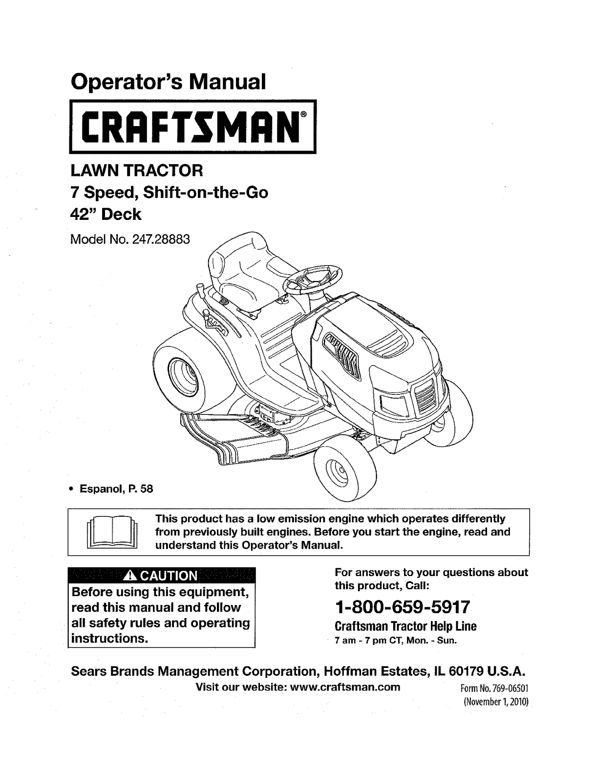
Operator's Manual
I:RRFTSMRN°
LAWN TRACTOR
7 Speed, Shift-on-the-Go
42" Deck
Model No. 247.28883
• Espanol, P. 58
This product has a low emission engine which operates differently
from previously built engines. Before you start the engine, read and
understand this Operator's Manual.
Before using this equipment,
read this manual and follow
all safety rules and operating
instructions.
For answers to your questions about
this product, Call:
1-800-659-5917
Craftsman Tractor Help Line
7 am -7 pm CT, Mon. -Sun.
Sears Brands Management Corporation, Hoffman Estates, IL 60179 U.S.A.
Visit our website: www.craftsman.com FormNo.769-06501
(November1,2010)
Warranty Statement .......................................................... 2
Safety Instructions ............................................................ 3
Slope Gauge ..................................................................... 8
Safety Labels ............. ....................................................... 9
Assembly ......................................................................... 10
Operation ........................................................................ 12
Service and Maintenance .............................................. 18
Off-Season Storage ........................................................ 27
Troubleshooting .............................................................. 28
Labels ............................................................................. 29
Parts List ......................................................................... 30
Espaffol............................................................................ 57
Service Numbers ............................................. Back Cover
CRAFTSMAN TWO YEAR FULL WARRANTY
FORTWO YEARSfromthedateof purchase,ifanynon-expendablepartof thisriding equipmentfails dueto adefectinmaterial orworkman-
ship,visitwww;craftsman.comorcall1-800-659-5917 toarrangefor free in-homerepair.
Theframe and front axle willbe repairedfree of chargefor five years fromthe dateof purchase if defectiveinmatedal or workmanship.
In attcases, if repair provesimpossible,the riding equipmentwillbe replaced free of charge withthe same or an equivalentmodel.
The battery willbe replaced freeof charge for 90 days from lhe date of purchaseif defective in materialor workmanship(our testing proves that it
willnot hold a charge).
This warrantyis void ifthis product is ever used whileproviding commercial servicesor if rented to another person.
This warranty covers ONLYdefects in material and workmanship.Warrantycoverage does NOTinclude:
• Expendableitemsthat can wearout from normal use withinthe warranty period, including butnot limitedto blades, spark plugs, air
cleaners,belts, andoil filters.
• Standardmaintenanceservicing,oil changes, or tune-ups.
• Tire replacementor repaircausedby puncturesfromoutside objects,such as nails,thorns; stumps,or glass.
• Tire orwheel replacementor repairresultingfrom normalwear, accident,or improperoperation or maintenance.
• Repairsnecessarybecause ofoperator abuse, including but not limitedto damage caused by towingobjects beyondthe capability of
the riding equipment,impacting objects that bendthe frame or crankshaft,or over-speedingthe engine.
•Repairsnecessarybecause of operator negligence, including but notlimitedto, electrical and mechanical damage causedby improper
Storage,failure to use the propergrade and amount of engineoil, failure to keepthe deckclear of flammabledebris,or failureto
maintainthe ridingequipmentaccording to the instructionscontained in theoperator's manual.
•Engine(fuel system)cleaning or repairs caused byfuel determinedto becontaminatedor oxidized (stale). tn general,fuel should be
used within30 daysof its purchasedate.
•Normal deteriorationand wearof the exterior finishes, or product labelreplacement.
Thiswarrantygivesyouspecificlegalrights,andyoumayalsohaveotherrightswhichvaryfromstateto state.
SearsBrandsManagementCorporation,HoffmanEstates,]L 60179
EngineOil: SAE30
Fuel: UnleadedGasoline
Spark Plug: Champion®RC12YC
Engine: Briggs & Stratton I/C®
ModelNumber:
SerialNumber:
Dateof Purchase:
Recordthe model number,serial number,
and date of purchaseabove.
© KCD FRLLC 2
Thissymbolpointsoutimportantsafetyinstructionswhich,if not
followed,couldendangerthepersonalsafetyand/orpropertyof
yourselfandothers.Readandfollowallinstructionsinthismanual
beforeattemptingtooperatethismachine.Failuretocomplywith
theseinstructionsmayresultinpersonalinjury.Whenyouseethis
symbol,HEEDITSWARNING!
Thismachinewasbuiltto beoperatedaccordingtothesafeopera-
tionpracticesinthismanual.As withanytypeof powerequipment,
carelessnessorerroronthepartoftheoperatorcanresultinserious
injury.Thismachineis capableofamputatingfingers,hands,toes
andfeetandthrowingdebris.Failuretoobservethefollowingsafety
instructionscouldresultinseriousinjuryordeath.
CALIFORNIA PROPOSITION 65
EngineExhaust,someof itsconstituenls,andcertainvehicle
componentscontainoremitchemicalsknownto Stateof California
to causecancerandbirthdefectsorotherreproductiveharm.
Batteryposts,terminals,andrelatedaccessoriescontain]eadand
leadcompounds,chemicalsknowntotheStaleofCaliforniato
causecancerandreproductiveharm.Washhandsafterhandling.
IIIIHIIIIIIIIIIIIIIIIIIIIII II I
GENERAL OPERATION
,Read,understand,andfollowallinstructionsonthemachineand
inthemanual(s)beforeattemptingtoassembleandoperate.
Keepthismanualinasafeplaceforfutureandregularreference
andfor orderingreplacementparts.
• Befamiliarwithall controlsandtheirproperoperation.Knowhow
tostopthemachineanddisengagethemquickly.
• Neverallowchildrenunder14yearsoldtooperatethismachine.
Children14yearsoldandovershouldreadandunderstandthe
operationinstructionsandsafetyrulesinthismanualandshould
betrainedandsupervisedbya parent.
• Neverallowadultstooperatethismachinewithoutproper
instruction.
•Tohelpavoidbladecontactora thrownobjectinjury,keep
bystanders,helpers,childrenandpetsat least75feetfromthe
machinewhileitis inoperation.Stopmachineif anyoneenters
thearea.
Thoroughlyinspecttheareawheretheequipmentistobeused.
Removeallstones,sticks,wire,bones,toys,andotherforeign
objectswhichcouldbepickedupandthrownbythe blade(s).
Thrownobjectscancauseseriouspersonalinjury.
•Planyourmowingpatterntoavoiddischargeof materialtoward
roads,sidewalks,bystandersandthelike.Also,avoiddischarg-
ingmaterialagainstawallorobstructionwhichmaycause
dischargedmaterialto ricochetbacktowardtheoperator.
Your Responsibility--Restricttheuseofthispowermachineto
personswhoread,understandandfollowthewarningsandinstruc-
tionsinthismanualandonthemachine,
SAVE THESE INSTRUCTIONS!
LI
•Alwayswearsafety glassesor safety gogglesduring operation
and while performingan adjustmentor repairto protect your eyes.
Thrown objectswhich ricochetcan causeserious injury to the
eyes.
, Wearsturdy,rough-soledwork shoes and close-fitting slacksand
shirts. Loosefitting clothesand jewelry can be caught in movable
parts.Never operatethis machineinbarefeet or sandals.
•Be aware of the mower and attachmentdischarge directionand
donot pointit at anyone. Do not operatelhe mowerwithoutthe
discharge cover or entire grass catcherin its proper place.
•Donot put handsor feet near rotatingpartsor under the cutting
deck. Contact with the blade(s) canamputate hands andfeet.
• A missingor damageddischarge cover can cause bladecontact
or thrownobject injuries.
• Stop the blade(s) whencrossing gravel drives,walks, or roads
and while not cutting grass.
•Watch fortraffic whenoperating near or crossingroadways.This
machine is not intendedfor use onany publicroadway.
•Do not operatethe machinewhile under the influenceof alcohol
or drugs.
•Mowonly in daylightor goodartificiallight.
•Nevercarry passengers.
• Disengageblade(s) beforeshifting intoreverse. Back up slowly.
Always look down and behind beforeand while backing to avoid a
back-overaccident.
3
Slowdownbeforeturning.Operatethemachinesmoothly.Avoid
erraticoperationandexcessivespeed.
* Disengageblade(s),setparkingbrake,stopengineandwaituntil
theblade(s)cometo acompletestopbeforeremovinggrass
catcher,emptyinggrass,uncloggingchute,removinganygrassor
debris,or makinganyadjustments.
• Neverleavearunningmachineunattended.Alwaysturnoff
blade(s),setparkingbrake,stopengineandremovekeybefore
dismounting.
• Useextracarewhenloadingorunloadingthemachineintoa
trailerortruck.Thismachineshouldnotbedrivenupordown
ramp(s),becausethemachinecouldlip over,causingserious
personalinjury.Themachinemustbepushedmanuallyon
ramp(s)toloadorunloadproperly.
° Mufflerandenginebecomehotandcancausea burn.Donot
touch.
• Checkoverheadclearancescarefullybeforedrivingunderlow
hangingtreebranches,wires,dooropeningsetc.,wherethe
operatormaybestruckorpulledfromthemachine,whichcould
resultinseriousinjury.
, Disengageallattachmentclutchesanddepressthebrakepedal
completelybeforeattemptingtostartengine.
• Yourmachineis designedtocutnormalresidentialgrassof a
heightnomorethan10".Donotattemptto mowthroughunusually
tall,drygrass(e.g.,pasture)orpilesofdryleaves.Drygrassor
leavesmaycontacttheengineexhaustand/orbuilduponthe
mowerdeckpresentinga potentialfirehazard.
• Useonlyaccessoriesandattachmentsapprovedforthismachine
bythe machinemanufacturer.Read,understandandfollowall
instructionsprovidedwiththeapprovedaccessoryorattachment.
Fora listof approvedaccessoriesandattachments,call1-800-
659-5917.
• Dataindicatesthatoperators,age60yearsandabove,are
involvedinalargepercentageof ridingmower-relatedinjuries.
TheseoperatorsshouJdevaluatetheirabilityto operatetheriding
mowersafelyenoughto protectthemselvesandothersfrom
seriousinjury.
° Ifsituationsoccurwhicharenotcoveredinthismanual,usecare
andgoodjudgment.Contactt-800-659-5917for informationand
assistance.
SLOPE OPERATION
Slopesareamajorfactorrelatedtolossofcontrolandtip-over
accidentswhichcanresultinsevereinjuryordeath.Allslopesrequire
extracaution,ifyoucannotbackuptheslopeorifyoufeeluneasyon
it,do notmowit.
Foryoursafety,usetheSlopeGuideincludedaspartofthismanual
tomeasureslopesbeforeoperatingthismachineonaslopedorhilly
area.Iftheslopeisgreaterthant5 degreesasshownontheSlope
Guide,donotoperatethismachineonthatareaorseriousinjurycould
result.
Do:
oMowup and downslopes, notacross. Exercise extreme caution
whenchanging directionon slopes.
•Watch for holes, ruts, bumps, rocks,or other hiddenobjects.
Uneventerrain couldoverturnthe machine.Tall grass canhide
obstacles.
* Useslowspeed. Choose a low enough speed setting so that
you willnothave to stop or shift whileon the slope. Tires may
lose tractionon slopeseven thoughthe brakesare functioning
properly.Alwayskeep machinein gear when going down slopes
to takeadvantageof enginebraking action.
• Followthe manufacturer'srecommendationsfor wheelweights
or counterweightsto improvestability.For recommendations,call
1-800-659-5917.
• Use extra care withgrass catchersor other attachments. These
can change the stability of the machine.
• Keep all movementonthe slopesslow and gradual. Donot make
suddenchanges in speed or direction. Rapidengagementor
brakingcould cause thefront of the machine to lift and rapidlyflip
over backwardswhich couldcause seriousinjury.
* Avoid startingor stopping ona slope. If tires losetraction,disen-
gage the blade(s) and proceedslowly straightdown the slope.
Do Not:
• Do not turn on slopes unlessnecessary; then,turn slowly and
gradually downhill,ifpossibEe,
•Do not mownear drop-offs,ditches or embankments.The mower
could suddenlyturn over ffa wheel is over the edgeof a cliff,
ditch, or if an edge caves in.
•Do not try to stabilizethe machineby puttingyour foot on the
ground.
•Do not use a grass catcheron steep slopes.
• Do not mow on wet grass.Reducedtraction couldcause sliding.
°Do not attemptto coast downhill.Over-speedingmaycausethe
operatorto lose controlof themachine resultingin serious injury
or death.
•Do nottow heavypull behind attachments(e.g. leadeddumpcart,
lawnroller, etc.) onslopes greaterthan 5 degrees.When going
downhill, the extra weighttends to pushthe tractor and may
causeyou to loosecontrol(e.g.tractor mayspeed up,brakingand
steeringability are reduced,attachmentmayjack-knife and cause
tractor to overturn).
4
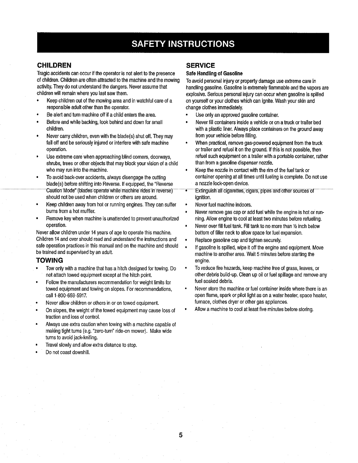
CHILDREN
Tragicaccidentscan occur ifthe operator is notalert tothe presence
of children. Children are often attractedto the machine andthe mowing
activity.They do not understandthe dangers. Neverassume that
children will remainwhereyoulast saw them,
•Keep childrenout of the mowing areaand in watchful care of a
responsibleadult other than the operator.
•Be alert and turn machineoff if a child entersthe area,
• Before and while backing,Fookbehind and downfor small
chUdren,
• Never carrychildren, evenwith the blade(s) shut off.They may
fail off and be seriouslyinjured or interferewith safe machine
operation.
•Use extreme care whenapproaching blind corners,doorways,
shrubs,trees or otherobjects that may block your vision of a child
who may run into the machine.
•Toavoid back-overaccidents,always disengagethe cutting
SERVICE
Safe Handlingof Gasoline
Toavoid personal injury or property damageuse extremecare in
handlinggasoline.Gasolineis extremelyflammable andthe vapors are
explosive.Serious personal iniurycan occur whengasoline is spilled
onyourself or your clotheswhich canignite. Washyour skin and
changeclothes immediately.
•Useonly an approved gasoline container.
•Neverfill containersinsidea vehicleor ona truck ortrailer bed
witha plastic liner.Alwaysplacecontainerson the groundaway
from your vehicle beforefilling.
•When practical, remove gas-poweredequipment from the truck
or trailer and refuel iton the ground.If this isnot possible, then
refuelsuch equipment ona trailer with a portablecontainer,rather
than from a gasoline dispenser nozzle.
,Keep the nozzle in contactwiththe rim of the fueltank or
container opening at all times until fueiing is complete.Do notuse
blade(s) beforeshifting into Reverse,If equipped,the "Reverse a nozzle lock-open device.
............................. -Caoti-on-Mode_-(bla-d-e+s-_p-e-rate-whiJ_m+a_hin-e-tPde-s_n-t_v_ts-e)-....... +-- -E:<tih-g_|_h-all-cig_t_ttes_-cig_T-pip_-8._-d_th_u_e_ f
should notbe used whenchildren or others are around.
•Keepchildren awayfrom hot or running engines.They cansuffer
burnsfrom a hot muffler.
•Removekeywhen machineis unattendedto prevent unauthorized
operation.
Neverallow childrenunder 14years of ageto operatethis machine.
Children _4and overshould readand understandthe instructions and
safe operation practicesin this manual andon themachine and should
be trained and supervised by an adult.
TOWING
• Towonly witha machinethat hasa hitchdesigned for towing. Do
not attachtowed equipmentexcept at the hitch point.
•Followthe manufacturersrecommendationfor weightlimits for
towed equipmentand towingon stopes. Forrecommendations,
call 1-800-659-5917.
•Neverallow childrenor others in or on towed equipment.
•On slopes, the weightof thetowed equipment maycause loss of
tractionand loss of control
• Alwaysuse extra cautionwhentowing with a machine capableof
making tightturns (e.g."zero-turn" ride-on mower). Make wide
turns to avoidjack-knifing.
• Travelslowlyand allow extra distance to stop.
• Do notcoast downhill.
ignition.
•Neverfuel machine indoors.
, Neverremove gas cap or add fueI whilethe engineis hotor run-
ning.Allow engine to cool at least two minutes before refueling.
o Neverover fill fuel tank. Filltank tono morethan _/2inchbelow
bottom of filler neckto allowspace for fuel expansion.
°Replacegasoline cap and tightensecurely.
•If gasolineis spilled, wipe it off the engineand equipment. Move
machine to another area.Wait 5 minutes beforestarting the
engine.
•To reducefire hazards, keepmachinefree of grass, leaves,or
other debris build-up.Clean up oil or fuel spillageand remove any
fuel soakeddebris.
° Neverstore the machine orfuel container inside wherethere is an
open flame, spark or pilot light as on a water heater,space heater,
furnace,clothes dryer or othergas appliances.
• Allowa machineto cool at leastfive minutes beforestoring.

GeneralService
• Neverrunanengineindoorsorina poorlyventilatedarea.Engine
exhaustcontainscarbonmonoxide,anodorless,anddeadlygas.
,Beforecleaning,repairing,orinspecting,makecertainthe
blade(s)andallmovingpartshavestopped.Disconnectthespark
plugwireandgroundagainsttheenginetopreventunintended
starting.
• Periodicallychecktomakesurethebladescometocomplete
stopwithinapproximately(5)fivesecondsafteroperatingthe
bladedisengagementcontrol.Ifthebladesdonotstopwithinthe
thistimeframe,yourmachineshouldbeservicedprofessionally
bya Searsorotherqualifiedservicedealer
, Checkbrakeoperationfrequentlyasitis subjectedtowearduring
normaloperation.Adjustandserviceas required.
• Checktheblade(s)andenginemountingboltsatfrequent
intervalsfor propertightness.Also,visuallyinspectblade(s)
fordamage(e.g.,excessivewear,bent,cracked).Replacethe
blade(s)withtheoriginalequipmentmanufacturer's(O.E.M.)
blade(s)only,listedinthismanual.Useofpartswhichdonot
meettheoriginalequipmentspecificationsmayleadtoimproper
performanceandcompromisesafety]
• Mowerbladesaresharp.Wrapthebladeorweargloves,anduse
extracautionwhenservicingthem.
•Keepallnuts,bolts,andscrewstighttobesuretheequipmentis
insafeworkingcondition.
• Nevertamperwiththesafetyinterlocksystemorothersafety
devices.Checktheirproperoperationregularly.
•Afterstrikingaforeignobject,stoptheengine,disconnectthe
sparkplugwire(s)andgroundagainsttheengine.Thoroughly
inspectthemachineforanydamageRepairthedamagebefore
startingandoperating.
• Neverattemptto makeadjustmentsorrepairsto themachine
whiletheengineisrunning.
• Grasscatchercomponentsandthedischargecoveraresubject
to wearanddamagewhichcouldexposemovingpartsor allow
objectsto bethrown.Forsafetyprotection,frequentlycheck
componentsandreplaceimmediatelywithoriginalequipment
manufacturer's(O.E.M.)partsonly,listedinthismanua].Useof
partswhichdonotmeettheoriginalequipmentspecificationsmay
leadto improperperformanceandcompromisesafety!
• Donotchangetheenginegovernorsettingsorover-speedthe
engine.Thegovernorcontrolsthemaximumsafeoperatingspeed
oftheengine.
° Maintainorreplacesafetyandinstructionlabels,asnecessary.
°Observeproperdisposallawsandregulationsforgas,oil,etc.to
protecttheenvironment.
o Accordingto theConsumerProductsSafetyCommission(CPSC)
andtheU.S.EnvironmentalProtectionAgency(EPA),thisproduct
hasanAverageUsefulLifeof seven(7)years,or270hours
ofoperation.At theendoftheAverageUsefulLife,buya new
machineorhavethemachineinspectedannuallybya Searsor
otherqualifiedservicedealertoensurethatallmechanicaland
safetysystemsareworkingproperlyandnotwornexcessively,
Failureto dosocanresultinaccidents,injuriesordeath.
DO NOT MODIFY ENGINE
Toavoidseriousinjuryordeath,donotmodifyengineinanyway.
Tamperingwiththe governorsettingcanleadtoa runawayengineand
causeitto operateat unsafespeeds.Nevertamperwithfactorysetting
of enginegovernor.
NOTICE REGARDING EMISSIONS
EngineswhicharecertifiedtocomplywithCaliforniaandfederal
EPAemissionregulationsforSORE(SmallOffRoadEquipment)are
certifiedto operateonregularunleadedgasoline,andmayinclude
thefollowingemissioncontrolsystems:EngineModification(EM)and
ThreeWayCatalyst(TWC)if soequipped.
SPARK ARRESTOR
.....Ir;
This machineis equippedwith an internalcombustion engineand
should not be used on or near any unimprovedforest-covered,
brushcoveredor grass-coveredland unlessthe engine'sexhaust
system isequippedwith a spark arrestor meetingapplicablelocal or
state laws(if any).
If a spark arrestoris used, it should be maintainedin effective working
order by the operator.In the Stateof Californiathe aboveis required
by law (Section4442 of the California Public ResourcesCode). Other
statesmay havesimilar laws. Federaltawsapply on federal lands.
A spark arrestorfor the muffleris available throughyour nearest Sears
Parts and Repair Service Center.
6

SAFETY SYMBOLS
Thispagedepictsanddescribessafetysymbolsthatmayappearonthisproduct.Read,understand,andfollowatlinstructionsonthemachine
beforeattemptingtoassembleandoperate.
O
READTHE OPERATOR'SMANUAL(S)
Read, understand, and follow all instructions in the manual(s) before attempting to assemble and
operate
DANGER-- ROTATINGBLADES
Never carry passengers. Never carry children, even with the blades off,
Do not put hands or feet near rotating parts or under the cutting deck. Contact with the blade(s)
can amputate hands and feet.
,,, ,,,
WARNING--THROWN OBJECTS
This machine may pick up and throw and objects which can cause serious personal injury.
WARNING--THROWN OBJECTS
This machine may pick up and throw and objects which can cause serious personal injury.
_, DANGER-- ROTATINGBLADES
Always look down and behind before and while backing to avoid a back-over accident.
WARNING-- ROTATING BLADES
BYSTANDERS
Keep bystanders, helpers, children and pets at least 7.5feet from the machine while it is in
operation.
WARNING-- SLOPEOPERATION
Do not operate this machine on a slope greater than 15 degrees.
WARNING-- HOT SURFACE
Engine parts, especia]Iy the muffler, become extremely hot during operation. Allow engine and
muffler to cool before touching.
&,
DANGER-- ROTATINGBLADES
To reduce the risk of injury, keep hands and feet away. Do not operate unless discharge cover or grass
catcher isin its proper place. If damaged, replace immediately.
7
oo
Sightandholdthislevalwitha _rtica] tree...
ora comerofabuilding...
50
orafencepost
o
m
m
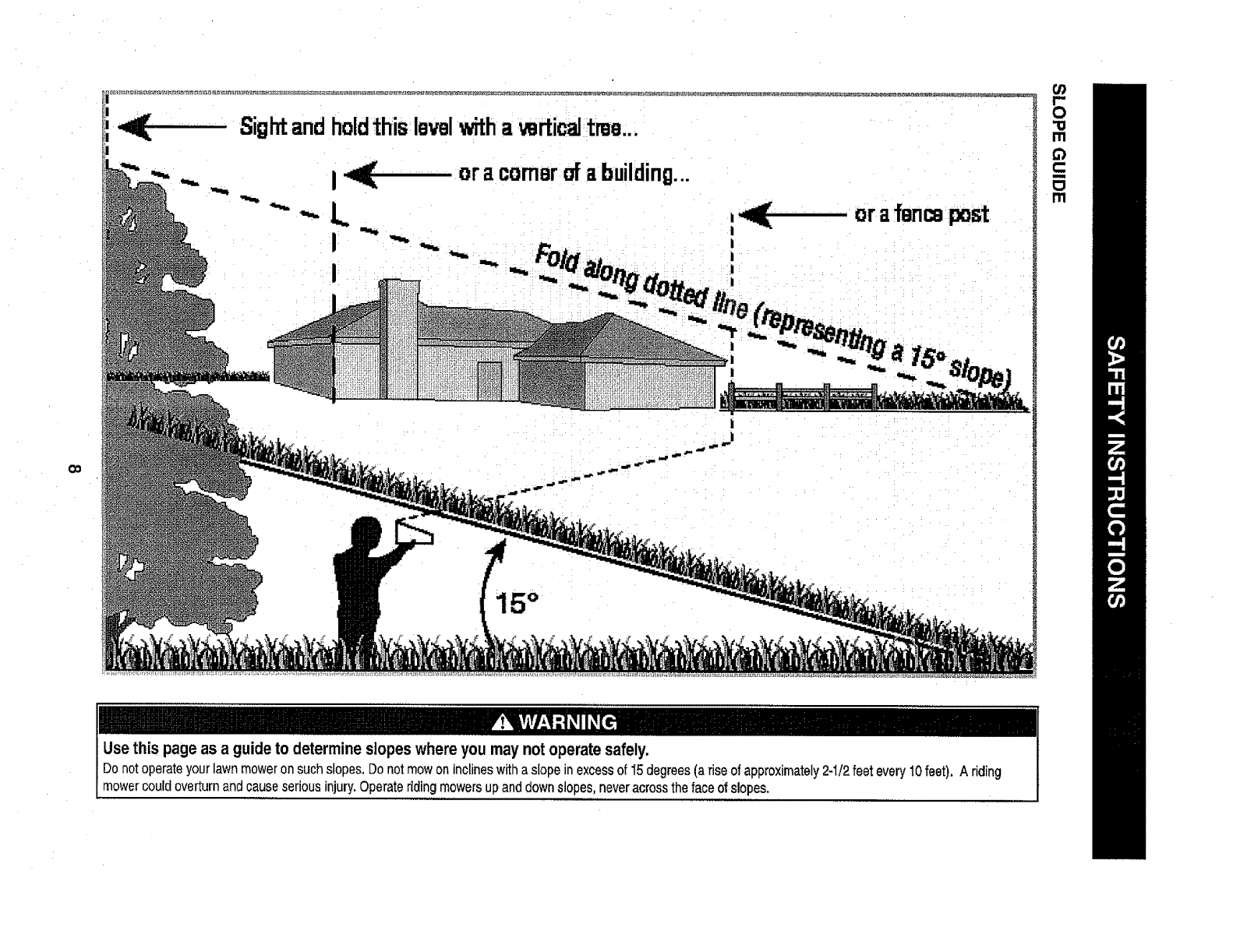
Usethispageas a guideto determineslopeswhereyoumaynotoperatesafely.
mowercouldoverturn and causeserious injury.Operate riding mowersupand down slopes, neveracross the face of slopes.
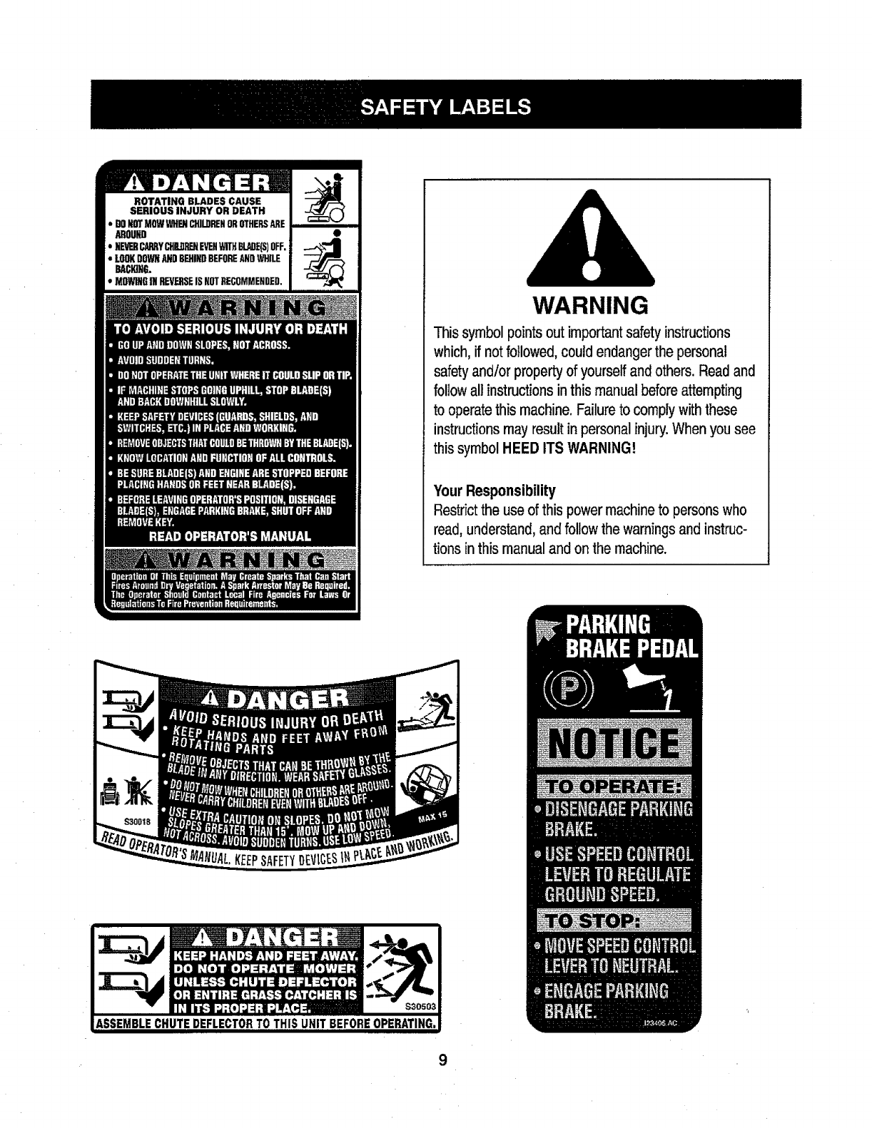
ROTATING BLADES CAUSE i
SERIOUS INJURY OR DEATH I
DONOTMOWWHENCH]InRENOROTHERSAREI
Mou_ I •
NEVEHCARRYCHDRENEVEHWiTHBLeaE(S)OFF,I
LOOKDOWNNil) BEHINDBEFOREANDWHILE |
_c_,G. I
MOWINGfli REVERSEIS NOTRECOMMENDED.J WARNING
This symbol points outimportantsafety instructions
which, if not followed, could endanger the personal
safety and/or property of yourself and others. Read and
follow all instructionsin this manual before attempting
to operate this machine. Failure to comply with these
instructions may result in personal injury. When you see
this symbol HEED ITS WARNING!
Your Responsibility
Restrict the use of thispower machine to persons who
read, understand, and follow the warnings and instruc-
tions inthis manual and on the machine.

IMPORTANT:Yourtractorisshippedwithmotoroilinthe engine.
However,youMUSTchecktheoillevelbeforeoperating.Referto the
Service& Maintenancesectionfor instructionsoncheckingtheoil
level.
Attaching the Battery Cables
CALIFORNIA PROPOSITION 65
Batteryposts,terminals,andrelatedaccessoriescontainleadand
leadcompounds,chemicalsknowntotheStateofCaliforniato
causecancerandreproductiveharm.Washhandsafterhandling.
Shipping Brace Removal
Makesuretheridingmower'sengineisoff,removetheignitionkey,
andsettheparkingbrakebeforeremovingtheshippingbrace.Refer
totheOperationsectionfor instructionsonhowtosetthe parking
brake.
•Locatetheshippingbrace,if present,andaccompanyingwarning
tagfoundontherightsideof themower,betweenthedischarge
chutedeflectorandthecuttingdeck.SeeFig.2.
Forshippingreasons,bothbatterycablesonyourequipmentmay
havebeenleftdisconnectedfromtheterminalsatthefactory.To
connectthe batterycables,proceedasfollows:
NOTE:Thepositivebatteryterminalis markedPos.(+).Thenegative
batteryterminalismarkedNeg.(-).
1. Removethe plasticcover,if present,fromthe positivebattery
terminalandattachthe redcableto thepositivebatteryterminal
(+)withtheboltandhexnut.SeeFigure1.
2. Removetheplasticcover,if present,fromthe negativebattery
terminalandattachthe blackcableto thenegativebattery
terminal(-) withtheboltandhexnut.SeeFigure1.
f
3.
Figure 1
Positionthe redrubberbootoverthepositivebatteryterminal to help
protectitfrom corrosion.
NOTE:If the battery is put intoservice after the date shownon top of
battery,charge the battery as instructedin the Service & Maintenance
section of thismanual priorto operatingthetractor.
_,,, J
Figure2
•Placethedeckliftleverinthehighestcuttingposition.Referto
SettingtheCuttingHeightintheOperationsectionofthismanual.
• Whilepushingthedischargechutedeflectortowardsthemachinewith
yourlefthand,removetheshippingbracew_ yourrighthandbygrasp-
ingitbetweenyourthumbandindexfingerandrotatingitclockwise.
Theshipping brace,used for packagingpurposes only, must be
removedand discarded before operating your riding mower.
Attaching The Steering Wheel
If the steering wheelfor your tractor did notcome attached,the
hardwarefor attaching ithas been packedwithin the steeringwheel,
beneaththe steeringwheelcap. Carefullypry off the steeringwheel
cap and removethe hardware.
1. Withthe wheels of the tractor pointing straightforward, placethe
steeringwheel over the steeringshaft.
2. Ptacethe washer(with the cuppedside down)overthe steering
wheeland securewith the hex bolt. See Fig, 3-3.
10
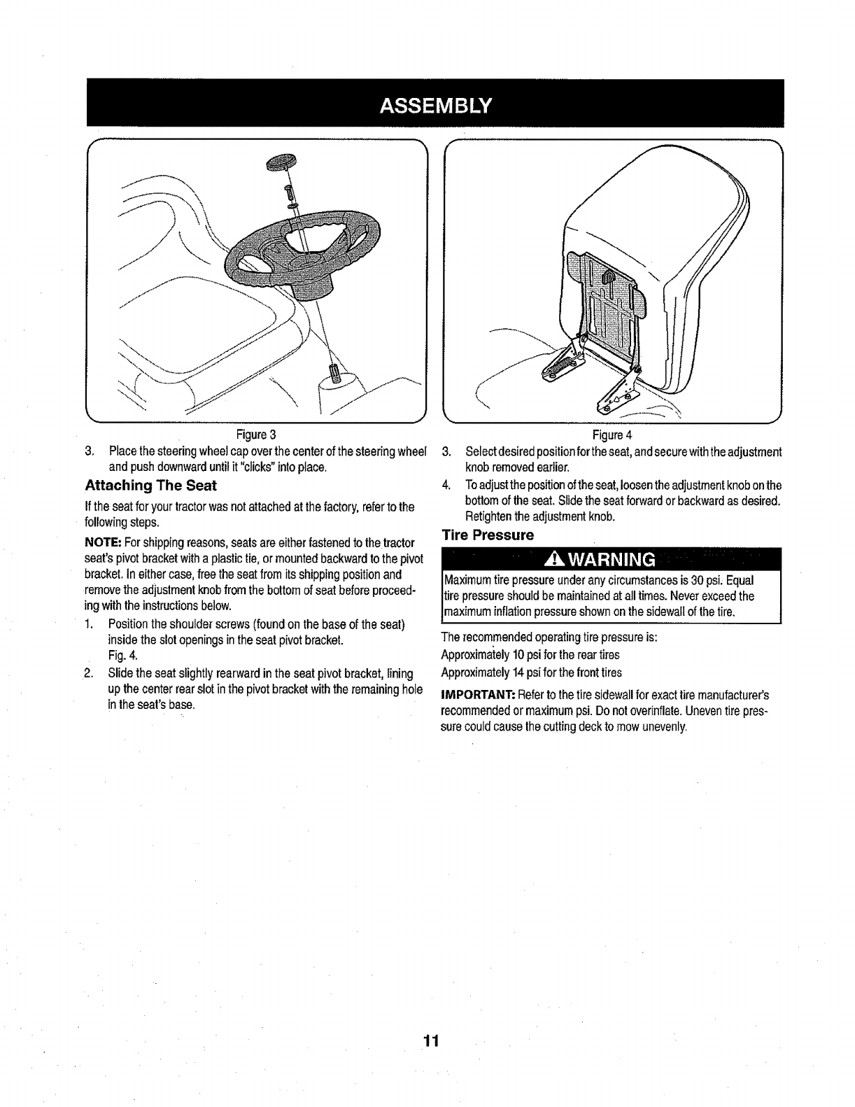
Figure3
3. Placethe steering wheelcap over the centerof the steeringwheeI
and push downwarduntil it "clicks"into place.
Attaching The Seat
Ifthe seatfor your tractor was notattached at thefactory, referto the
following steps.
NOTE: Forshipping reasons, seals are either fastened to the tractor
seat's pivot bracketwith a plastic tie, or mounted backwardto the pivot
bracket, In either case, freethe seatfrom itsshipping positionand
remove the adjustmentknob fromthe bottomof seat before proceed-
ing withthe instructions below.
1. Position the shoulder screws(found on the base of the seat)
inside the slot openings inthe seat pivot bracket.
Fig. 4.
2. Slide the seat slightly rearward in the seat pivot bracket, lining
up the center rear slot inthe pivotbracket withthe remaininghole
in the sears base.
\
1
Figure 4
3. Selectdesired position fortheseat, andsecurewiththeadjustment
knob removedeadier.
4, Toadjustthe positionofthe seat,loosenthe adjustmentknobonthe
bottom of the seat. Slide the seatforward or backwardas desired.
Fletightenthe adjustmentknob.
Tire Pressure
pressureshould be maintainedat all times. Neverexceedthe
maximum inflationpressure shownonthe sidewall ofthe tire.
The recommendedoperatingtire pressureis:
Approximately10psi for the reartires
Approximately 14 psi for the fronttires
IMPORTANT: Referto thetire sidewall for exacttire manufacturer's
recommendedor maximumpsi. Do not overinflate.Uneventire pres-
sure could cause the cutting deck to mowunevenly.
11
f
B
H
G
F
A
E
D
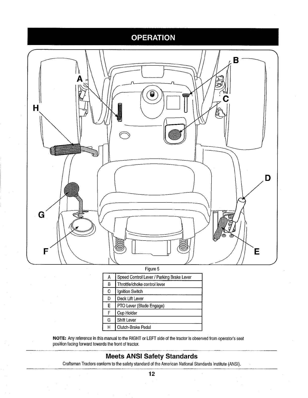
Figure5
A Speed Control Lever/Parking BrakeLever
B Throttle/choke controllever
C IgnitionSwitch
D Deck Lift Lever
E PTO Lever(Blade Engage)
F ,,,Cup,,,Holder
G Shift Lever
H Clutch-Brake Pedal
NOTE-Anyreferenceinthismanualtothe RIGHTor LEFTsideofthetractoris observedfromoperator'sseat
positionfacingforwardtowardsthefrontoftractor.
Meets ANS! Safety Standards
Craftsman Tractorsconform to the safetystandard of the American National StandardsInstitute (ANSI).
12
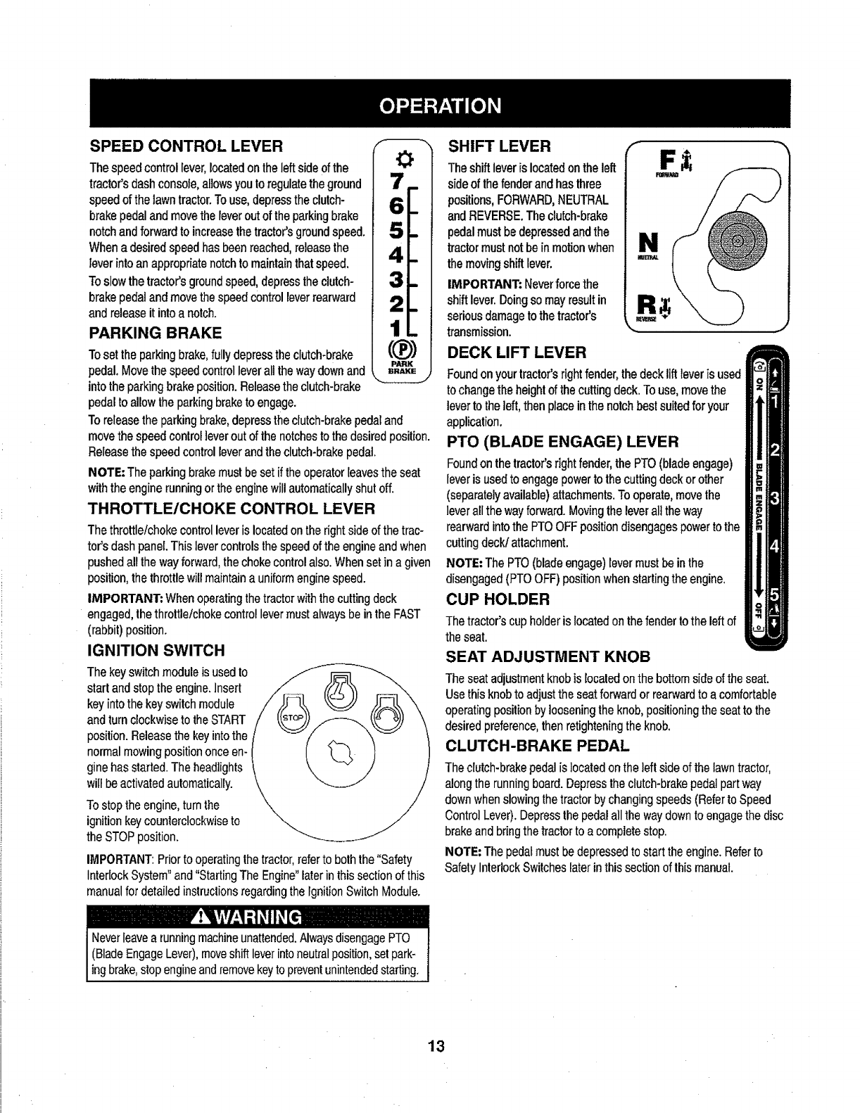
SPEEDCONTROLLEVER
The speed control lever, locatedonlhe left side of the
tractor's dash console, allows youto regulatethe ground
speed of the lawn tractor.Touse, depressthe clutch-
brake pedal and movethe leverout of the parkingbrake
notchand forward to increasethe tractor's ground speed.
Whena desired speedhas been reached,releasethe
lever intoan appropriate notchto maintainthat speed.
To slow the tractor's groundspeed,depress the clutch-
brakepedal and movethe speed control lever rearward
and release it into a notch.
PARKING BRAKE
Tosetthe parkingbrake,fullydepresstheclutch-brake
pedal.Movethespeedcontrolleverallthewaydownand
intotheparkingbrakeposition.Releasetheclutch-brake
pedaltoallowthe parkingbraketoengage.
I
i
((!b)
P/iRK
To releasethe parkingbrake,depress theclutch-brake pedaland
move the speed controllever out of the notchesto the desiredposition.
Release the speed control leverand theclutch-brake pedal.
NOTE: The parkingbrakemust beset if the operatorleavesthe seat
withthe engine running or theenginewill automaticallyshut off.
THROTTLE/CHOKE CONTROL LEVER
The throttle/choke controllever is located onthe right side of the trac-
tor's dash panel.This levercontrols thespeed of the engineand when
pushed all the wayforward,the choke controlalso.When set in a given
position,the throttle will maintain a uniformengine speed.
IMPORTANT: Whenoperating thetractor withthecuttingdeck
engaged,thethrottle/choke control levermust alwaysbe in the FAST
(rabbit) position.
IGNITION SWITCH
The key switch module is used to
start and stop the engine. Insert
key intothe key switch module
and turn clockwise to the START
position.Releasethe keyintothe
normal mowingposition once en-
gine has started. The headlights
will beactivatedautomatically.
To stopthe engine,turn the
ignition key counterclockwiseto
the STOPposition.
IMPORTANT: Prior to operatingthetractor,referto both the "Safety
InterlockSystem"and "Starting The Engine"later in this section of this
manualfor detailed instructionsregardingthe IgnitionSwitch Module.
,_ !_liVlv/_,!it Iill [l,
Neverleavea running machineunattended,Alwaysdisengage PTO
(BladeEngage Lever),moveshift leverintoneutralposition,set park-
ng brake,stopeng neandremovekeyto preventunintendedstarting.
SHIFT LEVER
Theshift leveris locatedon theleft
side of the fender and has three
positions,FORWARD,NEUTRAL
and REVERSE,The clutch-brake
pedal must be depressedand the
tractor mustnot be in motionwhen
the movingshift lever,
IMPORTANT: Neverforce the
shift lever.Doingso mayresultin
seriousdamage to the tractor's
transmission.
DECK LIFT LEVER
Foundonyourtractor'srightfender,thedeckliftleveris used
tochangetheheightofthecuttingdeck.Touse,movethe
leverto theleft,thenplaceinthe notchbestsuitedforyour
application.
PTO (BLADE ENGAGE) LEVER
Foundonthetractor'srightfender,thePTO(bladeengage)
leveris usedtoengagepowerto thecuttingdeckor other
(separatelyavailable)attachments.Tooperate,movethe
leverallthewayforward.Movingthe leveralltheway
rearwardintothe PTOOFFpositiondisengagespowertothe
cuttingdeck/attachment.
NOTE:ThePTO(bladeengage)levermustbeinthe
disengaged(Pro OFF)positionwhenstartingthe engine.
CUP HOLDER
Thetractor's cup holderis located on thefender to the left of
the seat.
SEAT ADJUSTMENT KNOB
The seatadjustmentknob is located onthe bottom side of the seat.
Use this knob to adjust the seat forward or rearwardto a comfortable
operatingposition by loosening the knob, posilioning the seatto the
desired preference,then retighteningthe knob.
CLUTCH-BRAKE PEDAL
The clutch-brake pedalislocated ontheleft side of thelawntractor,
along the running board. Depressthe clutch-brake pedal part way
downwhen slowing thetractor by changing speeds(Referto Speed
ControlLever). Depressthe pedal allthe waydown to engage the disc
brakeand bring the tractor to a complete stop.
NOTE: The pedal must be depressed to start the engine. Referto
Safely InterlockSwitches later in this section of lhis manual.
13

Gas and Oil Fill-up
Oil
IMPORTANT:Yourtractorisshippedwithmotoroilintheengine.
However,youMUSTcheckthe oillevelbeforeoperating.Becareful
notto overfil!.
Forinstructionsonhowtochecktheengineoil,referto CheckingThe
EngineOilintheServiceandMaintenancesectionofthismanual.
Gasoline
Thegasolinetankis locatedunderthehood.Donotoverfill.
NOTE: Purchasegasolineinsmallquantities.Donotusegasolineleft
overfromthepreviousseason,to minimizegumdepositsinthefuel
system.
.Thisengineiscertifiedtooperateonunleadedgasoline.Forbest
results,fill thefueltankwithonlyclean,fresh,unleadedgasoline
witha pumpstickeroctaneratingof87orhigher.
•Gasohol(upto 10%ethylalcohol,90%unleadedgasofineby
volume)is anapprovedfuel.Othergasofine/alcoholblends,such
as E85,arenotapproved.
,MethylTertiaryButylEther(MTBE)andunleadedgasofineblends
(uptoa maximumof 15%MTBEbyvolume)areapprovedfuels.
Othergasoline/etherblendsarenotapproved.
•Fillfueltankoutdoorsorinwell-ventilatedarea.
•Donotoverfillfueltank.Filltankto nomorethan1/2inchbelow
bottomoffillerneckto allowspaceforfuelexpansion.
•Neverremovegascaporaddfuelwhiletheengineishotorrun-
ning.Allowenginetocoolat leasttwominutesbeforerefueling.
• Ifgasolineisspilled,wipeit offtheengineandequipment.Move
machinetoanotherarea.Wait5 minutesbeforestartingthe
engine.
TO Add Gasoline
F: " FLI"tR11'
1. Turnthe engine offand let engine cool at least 2 minutes before
removingthe fuel cap. The gasoline tank is locatedunder the
hood. Removethe fuel cap byturning it counterclockwise.
2. Fillthe fueltankwith gasoline.Useonly clean,fresh (no morethan
30daysold), unleadedgasoline.Filltankto no morethan 1/2 inch
below bottomof filler neckto allowspacefor fuelexpansion.
3. Reinstallthe fuel cap.
IMPORTANT: Do notoverfill thetank. Fill tankto no morethan 1/2
inch belowbottomof filler neck toallow spacefor fuel expansion.See
Fig. 6.
Figure 6
SAFETY INTERLOCK SYSTEM
The safety interlocksystemis designedfor safe operation ofthe trac-
tor. Ifthis systemshould ever malfunction,do not operatethe tractor.
Immediatelycontact 1-800-4-MY-HOMEto havethe systemserviced.
• The safety interlocksystem preventsthe enginefrom starting
unless the parkingbrake is engagedand the PTO (Blade Engage)
lever is in the disengaged(OFF) position.
• The safety interlocksystem willautomatically shut offthe engine if
the operatorleavesthe seat beforeengagingthe parkingbrake.
• Thesafetyinterlocksystemwillautomaticallyshut offthe engineif
theoperator leavesthe tractor'sseatwiththe PTO(BladeEngage)
leverengaged,regardlessof whethertheparkingbrakeis engaged.
•Theengine willautomaticallyshut offif the PTO(Blade Engage)
leveris movedinto the engaged(ON) position with the shift lever
in Reverse.
14
Avoid Serious Injury or Death
• Go UPand down slopes, notacross.
Avoidsudden turns.
Do not operatetheunit whereit couldslip or tip.
If machinestopsgoing uphill,stopblades and backdownhill
slowly.
Do not mowwhen childrenor othersare around.
Nevercarry children, evenwith blades off.
Look downand behind beforeand while backing.
Keep safety devices(guards,shields, and switches) inplace
and working.
Removeobjects that could be thrown by the blades,
Knowlocation and functionof allcontrols.
Be sure blades and engineam stoppedbefore placinghands or
feet nearblades.
•Before leavingoperator'sposition, stoptractor, disengage
blades,engage parkingbrake,shut engineoff, and removekey.
Read Operator's Manual
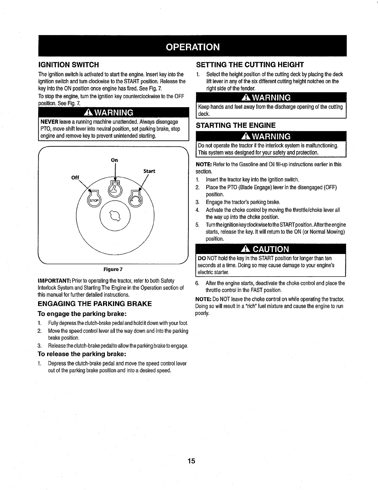
IGNITION SWITCH
Theignitionswitchis activatedto starttheengine,insertkeyintothe
ignitionswitchandturnclockwiseto theSTARTposition.Releasethe
keyintotheONposition onceenginehasfired.SeeFig.7.
Tostoptheengine,turnthe ignitionkeycounterclockwisetothe OFF
position.SeeFig.7.
SETTING THE CUTTING HEIGHT
1. Selecttheheightpositionof thecuttingdeckbyplacingthedeck
liftleverinanyofthesixdifferentcuttingheightnotchesonthe
rightsideofthefender.
NEVERleavea runningmachineunattended.Alwaysdisengage
PTO,moveshiftleverintoneutralposition,setparkingbrake,stop
engineandremovekeyto preventunintendedstarting.
On
Start
off
Figure 7
IMPORTANT:Priortooperatingthetractor,refertobothSafety
interlockSystemandStartingTheEngineintheOperationsectionof
thismanualforfurtherdetailedinstructions.
ENGAGING THE PARKING BRAKE
To engage the parking brake:
1. Fuflydepresstheclutch-brakepedalandholditdownwithyourfoot.
2. Movethespeedcontrolleverallthewaydownandintotheparking
brakeposition.
3. Releasetheclutch-brakepedaltoallowtheparkingbraketoengage.
To release the parking brake:
1. Depresstheclutch+brakepedalandmovethespeedcontrollever
outofthe parkingbrakepositionandintoadesiredspeed.
STARTING THE ENGINE
NOTE:RefertotheGasolineandOiJfill-upinstructionsearlierinthis
section.
1. Insertthetractorkeyintotheignitionswitch.
2. PlacethePTO(BladeEngage)leverinthedisengaged(OFF)
position.
3. Engagethetractor'sparkingbrake.
4. Activatethechokecontrolbymovingthethrottletchokeleverall
thewayupintothechokeposition.
5. TurntheignitionkeyclockwisetotheSTARTposition.Aftertheengine
starts,releasethekey.It willreturnto theON(orNormalMowing)
position.
DO NOT holdthe keyin theSTARTposition for longerthan ten
seconds at a time. Doing so maycause damage to your engine's
electric starter.
6. Aftertheengine starts, deactivatethechoke controland placethe
throttle control inthe FASTposition.
NOTE: Do NOTleave the chokecontrolonwhileoperatingthe tractor.
Doingso willresultin a "rich" fuel mixtureand cause the engineto run
poorly.
15
STOPPING THE ENGINE
Ifyoustrikeaforeignobject,stoptheengine,disconnectthespark
plugwire(s)andgroundagainsttheengine.Thoroughlyinspectthe
machineforanydamage.Repairthedamagebeforerestartingand
operating
1. ifthebladesareengaged,placethe PTO(BladeEngage)leverin
thedisengaged(OFF)position.
2. Turntheignitionkeycounterclockwiseto theSTOPposition.
3. Removethe keyfromtheignitionswitchto preventunintended
starting.
DRIVING THE TRACTOR
Avoidsudden starts, excessivespeed and suddenstops.
Do not leavethe seat of the tractorwithoutfirst placingthe PTO
(Blade Engage) leverin the disengaged(OFF) position,depressing
the brakepedal and engagingthe parking brake. If leavingthe tractor
unattended,also turn the ignitionkeyoff and removethe key.
1. Depressthe clutch-brakepedalto releasethe parking brakeand
then let the pedal up.
2. Movethe throttle leverintothe FAST(rabbit) position.
3. Placethe shift leverin eitherthe FORWARDor REVERSE
position.
IMPORTANT: Do NOT usethe shift leverto changethe directionof
travel whenthe tractor is in motion.Always usethe clutch-brake pedat
to bring the tractor to a complete stop beforeshifting.
4. Releasethe parking brakeby depressingtheclutch-brake pedal
and positioningthe speed controllever in the desiredposition.
IMPORTANT: First-timeoperatorsshould use speed positions1or
2. Become completelyfamiliarwiththe tractor'soperationand controls
before operating thetractor in higherspeed positions.
5. Releaseclutch-brakepedal slowly to put unit into motion.
6. The lawntractor isbroughtto a stop by depressingthe clutch-
brakepedal.
NOTE: Whenoperating the unitinitially,therewillbe little difference
betweenthe highesttwo speeds until after the belts haveseated
themselvesinto the pulleysduringthe break-inperiod.
rP1 [.el
WARNING! Beforeleavingthe operator'spositionfor any reason,
disengagethe blades,place the shift lever in neutral,engage the
parkingbrake,shut engine offand remove the key.
IMPORTANT;Whenstoppingthetractorforanyreasonwhileona
grasssurface,always:
1. Placetheshiftleverinneutral,
2. Engagetheparkingbrake,
3. Shutengineoffandremovethekey.Doingsowillminimizethe
possibilityofhavingyourlawn"browned"byhotexhaustfrom
yourtractor'srunningengine.
Ifunitstallswithspeedcontrolinhighspeed,or ifunitwillnotoperate
withspeedcontrolleverina lowspeedposition,proceedasfollows:
1+ PlaceshiftleverinNEUTRAL.
2. Restartengine.
3. Placespeedcontrolleverinhighestspeedposition.
4. Releaseclutch-brakepedalfully.
5+ Depressclutch-brakepedal.
6. Placespeedcontrolleverindesiredposition.
7. PlaceshiftleverineitherFORWARDor REVERSE,andfollow
normaloperatingprocedures.
DRIVING ON SLOPES
RefertotheSLOPEGAUGEinthe SafetyInstructionssectionofthe
manualtohelpdetermineslopeswhereyoumayoperatethistractor
safely.
Do not mowon inclines witha slopein excess of 15degrees(a rise
of approximately 2-1/2feet every 10 feet). The tractor couldoverturn
and cause seriousinjury.
• Mow up and down slopes, NEVERacross.
•Exercise extreme cautionwhenchangingdirection onslopes.
•Watch for holes, ruts, bumps, rocks,or other hiddenobjects.
Uneventerrain could overturnthe machine.Tallgrass can hide
obstacles.
, Avoidturns whendriving on a Slope.If a turn must be made,turn
downthe slope. Turningup a slopegreatly increasesthe chance
of a roll over.
•Avoidstoppingwhendriving upa slope. If it is necessaryto stop
whiledriving upa slope,start up smoothlyandcarefully to reduce
thepossibilityof flipping the tractor over backward.
ENGAGING THE BLADES
Engagingthe PTO(Blade Engage)transfers powerto thecutting deck
or other(separately available)attachments.To engage the blades,
proceedas follows:
1. Movethe throtUeichokecontrolleverto the FAST(rabbit) position.
2. Graspthe PTO (Blade Engage)leverand pivot itall theway
forward into theengaged(ON) position.
3. Keepthe throttle leverin the FAST(rabbit) positionfor the most
efficient use of the cutting deckor other (separatelyavailable)
attachments.
NOTE: The engine will automaticallyshut offif thePTO (Blade
Engage)lever is movedintothe engaged(ON) positionwith the shift
leverin Reverse.
16
MULCHING
A mulch kit isavailable asan attachment, Mulching isa processof
recirculating grassclippings repeatedly beneath the cutting deck,
The ultra-fine clippings arethen forced backinto the lawn where
. they act asa natural fertilizer.
A mulch kitcan be purchased.See the ReplacementParts & Attach-
mentssection of this manualfor more information.
USING THE DECK LIFT LEVER
Toraisethe cuttingdeck,movethedeck lift leverto the left, then place
it in the notch bestsuited for your application. Referto SettingThe
Cutting Height earlierin this Operationsection.
MOWING
I_he machine
while it is in operation. Stop machineif anyone entersthe area.
The followinginformation will be helpful when using the cutting deck
withyourtractor:
HEADLIGHTS
, The lamps are ON wheneverthe tractor's engineis running.
,The lamps turn OFF whenthe ignition keyis moved to the STOP
position.
Planyourmowingpatterntoavoiddischargeof materialstoward
roads,sidewalks,bystandersandthelike.Also,avoiddischarging
materialagainstawallorobstructionwhichmaycausedischarged
materialto ricochetbacktowardtheoperator.
• Do notmowat high groundspeed, especiallyifa mulch kitor
grass collector is installed.
• Forbest results it is recommendedthat the first two laps be cut
with the dischargethrowntowardsthe center.After the firsttwo
laps, reversethe direction tothrow the discharge to the outside
for the balance of cutting. This willgive a better appearanceto the
lawn.
•Do not cutthe grasstoo short. Short grass invitesweedgrowth
and yellowsquickly indry weather.
•Mowing should alwaysbe done with the engine at full throttle.
•Underheavier conditionsitmaybe necessary to go back overthe
cut areaa second timeto geta cleancut.
• Do NOT attemptto mowheavy brushand weedsand extremely
tall grass. Your tractor is designedto mow lawns, NOT clear
brush.
• Keep the blades sharp and replacethe blades whenworn. Refer
to Cutting Bladesin the-Servicesection of this manualfor proper
blade sharpening instructions.
17

MAINTENANCE SCHEDULE
Beforeperforminganytypeof maintanance/ser_ce,disengageall 1
controlsandstoptheengine.Waituntilallmovingpartshavecometo t
acompletestop.Disconnectsparkplugwireandgrounditagainstthe t
enginetopreventunintendedstarting.AlwayswearsafetyglassesduringI
operationorwhileperforminganyadjustmentsorrepairs, i
Followthemaintenanceschedulegivenbelow.Thischartdescribes
serviceguidelinesonly.UsetheServiceLogcolumntokeeptrack
ofcompletedmaintenancetasks.To locatethe nearestParts&
RepairServiceCenterorto scheduleservice,simplycontact
1-800-4-MY-HOME®.
I_ _[_l_j
BeforeEachUse
In the First FiveHours
Ever),10 Hours
Every25 hours
4. Check
5. Clean
6. Clean
8. Change
12. Clean
13. Clean
14. Lubricate
20. Clean
2I. Clean
22. Lubricate
1. Engineoi!level
2. Mufflerarea and controls
3. Fingerguard
7. EngineOil
9. Hood/Dash air vents
10. Battery terminals
11. Deck spindlesand idler
bracket
15. Air filter's precieaner*
16. Airfilter*
17. Mid steering arms, pivot
shafts, and axles
18. Front wheel bearings
19. Front deck wheels
25. Engine oil/Oil fitter
26. Muffler
29. Air filter
30. Air filter's pre-cfeaner
31. Sparkplug
32. Air coolingsystem*
33. Fuelfilter
34. SteeringGears
35. RearWheels
43. Hood/Dash air vents
44. Battery terminals
45. Mid steeringarms, pivot
shafts, and axles
46. Front wheel bearings
47. Front deck wheels
48. Deck spindlesand idler
bracket
49. Pedalpivot points
Every 50 hours
Annually
BeforeStorage
23.
24.
27.
28.
36.
37.
38.
39.
40.
41.
42.
50.
51.
52.
Lubricate
Lubricate
Change! Replace
Check
Replace
Replace
Replace
Clean
Replace
Clean
Removeand grease axles
Clean
Clean
Lubricate
53. Lubricate
54. Lubricate
55. Lubricate
56. Lubricate
*Service merefrequently under dustyconditions.
Before performing any maintenanceor repairs,disengage the PTO
(Blade Engage Lever),engage the parkingbrake,stop the engine
and remove the key to preventunintendedstarting.
Ifthe engine has been recently run,theengine,muffler and sur-
roundingmetal surfaceswill be hot and cancause burnsto the skin.
Exercisecautionto avoid burns.
18

ENGINE MAINTENANCE
Checking the Engine Oil
OnlyusehighqualitydetergentoilratedwithAPIserviceclassification
SF,SG,SH,orSJ.Selecttheoil'sSAEviscositygradeaccordingto
theexpectedoperatingtemperature.Followthechartbelow.
Althoughmulti-viscosityoils(5W20,10W30,etc.)improvestarting
incoldweather,theywillresultinincreasedoilconsumptionwhen
usedabove32°1:.Checkyourengineoillevelmorefrequentlytoavoid
possibleenginedamagefromrunninglowonoil.
/CColder _ 32°F _Warmer_
SAE30
Oil Viscosity Chart j
To checkthe engine oil, proceedas follows:
•Ensurethatthe tractoris ona levelsurface.
• Cleanthe oil fill areaof anydebris.
1. Removethedipstick and wipewitha cleancloth.
2, Insertand tightendipstick.
3. Removethedipstick and checkthe oil level.It should beat the
Full mark on the dipstick. See Figure 9.
Dipstick__
OilDrain
Sleeve
OilDrain
Valve
Figure 9
4. If low,add oil slowlyinto the engineoilfill. Do notoverfill.After
addingoil, wait one minuteand thenrecheckthe oil level.
5. Replaceand tightendipstick.
Changing Engine Oil
Theengineoilshouldbechangedinthefirst5 hoursandthenevery50
hoursor oncea season.Tochangethe engineoil,proceedas follows:
1. WithengineOFF butstill warm,disconnectsparkplugwireand
keepit awayfromspark plug.
2. Removethe oilfill capldipstickfromthe oilfill tube.SeeFigure9.
3. Turnthe steeringwheelall lhe wayto the rightto betterexposethe
drain plug.
4. Clipthe oil drainsleeve(packedwith this manual)onto theoil drain
port. Routetheoppositeendof the sleeve intoan appropriateoil
collectioncontainerwitha capacitygreatenough tocollectthe used
oil,
5. Removethe oildrain plug,The oilwill beginto drain outof the
engine.
6. Afterthe oilhasfinisheddraining,replacethe oil drain plugand
tighten.Becarefulnotto overtighten.
7. Removethe oitdrainsleeveand storefor lateruse.
8. Refillthe enginewithnew motoroil untilthe oillevelon thedipstick
readsFULL, Replacetheoil fill cap/dipstick.
It'_ist of safedisposal!
recyclingfacilities.
Changing the Oil Filter
"L Drainthe oilfromthe engineas describedabove.
2. Removethe oilfilterand disposeof properly.See Figure10.
-Oil Filter
J
Figure 10
3. Beforeyou installthenew oilfilter,lightlylubricatethe oil filter
gasketwith fresh,cleanoil.
4. Installthe oilfilterby hand untilthegasketcontacts the oilfilter
adapter,thentightentheoilfilter I/2 to 3/4turns,
5. Add oilas describedabove.
6. Startand run the engine.As theenginewarmsup,check for oil
leaks.
7. Stop theengineand check the oil level. It should beat the FULL
markon the dipstick.
19
Fuel Filter Air Cleaner
Gasolineanditsvaporsareextremelyflammableandexplosive.Fire
orexplosioncancausesevereburnsordeath.
, Keep gasoline awayfrom sparks,openflames, pilot lights, heat,
and other ignitionsources,
• Check fuel lines,tank, cap,and fittings frequentlyfor cracks or
leaks. Replaceif necessary.
• Before replacingthe fuelfilter,drain the fuel tank as per the
instructions below.
• Do not drainfuel whenthe engine is hot.Allow the engine
adequate timeto cool. Drainfuel into an approvedcontainer
outdoors, awayfrom open flame.
,, Drain anylarge volumeof fuelfrom the tank by disconnectingthe
fuel line fromthein-line fuel filternear theengine.
•Removethefuel line fromthe In-lineside (side towardsthefuel
tank)of the fuelfilter.
,Replacementparts must bethe same and installedin the same
positionas the original parts.
•If fuelspills, waituntil itevaporatesbefore starting engine.
• Before replacingthefuelfilter, drain the fuel tank.Otherwise,fuel
can leak out andcause a fire or explosion.
To Drainthe fuel:
I. Locatethefuelfilter,which isroutedon the left sideof theengine
betweenthe fueltank andthe carburetor,and maybeattachedto
the enginewith a tie strap.Cutthe tie strap,if present,then pinch
the in-lineclampon thefuelfilterwith a pairof pliers,slidethe
clamp upthefuel line.Pullthe fuellinefree from thefilterand place
the openendof the line intoan approvedcontainerto drainthe fuel.
To change the fuel filter:
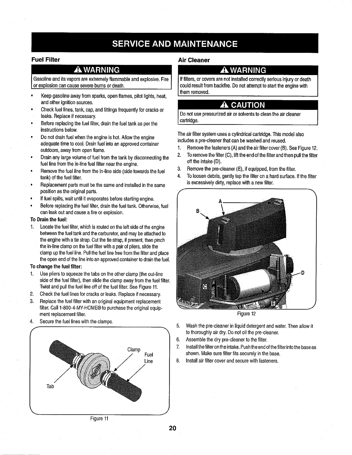
1. Use pliersto squeezethetabs on the other clamp (the out-line
side of the fuel filter), then slide the clamp awayfrom the fuelfilter,
Twistand pullthe fuelline off of the fuel filter.See Figure11.
2. Checkthe fuel linesfor cracks or leaks.Replace if necessary.
3. Replacethe fuel filterwithan original equipment replacement
filter. Call 1-800-4-MY-HOME@to purchasetheoriginalequip-
mentreplacementfilter.
4. Securethe fuel lines withthe clamps.
Clamp
Fuel
Line
Tab
Iffilters,orcoversarenotinstalledcorrectlysedousinjuryordeath
couldresultfrombackfire.Donotattempttostarttheenginewith
themremoved.
Donotusepressurizedairorsolventsto cleantheaircleaner
cartridge.
Theairfiltersystemusesa cylindricalcartridge.Thismodelalso
includesapre-cleanerthatcanbewashedandreused.
1. Removethefasteners(A)andtheairfiltercover(B),SeeFigure12.
2. Toremovethefilter(C),lifttheendofthefilterandthenpullthefilter
offtheintake(D).
3. Removethepre-cleaner(E),if equipped,fromthefilter.
4. Toloosendebris,gentlytapthefilterona hardsurface,if thefilter
is excessivelydirty,replacewithanewfilter.
A
Figure 12
J
5. Wash the pre-cleaner in liquid detergent andwater.Thenallow it
to thoroughlyair dry. Do not oilthe pre-cleaner.
6. Assemblethe dry pre-cleanerto thefilter.
7. Installthefilteron theintake.Pushthe endof thefilterintothe baseas
shown. Make surefilter fits securely inthe base.
8. Installair filter cover and secure with fasteners.
Figure11
.... J
2O
Spark Plug
1. Cleanareaaroundthesparkplugbase.Donotsandblastsparkplug.
Sparkplugshouldbecreanedbyscrapingorwirebrushingand
washingwithacommercialsolvent
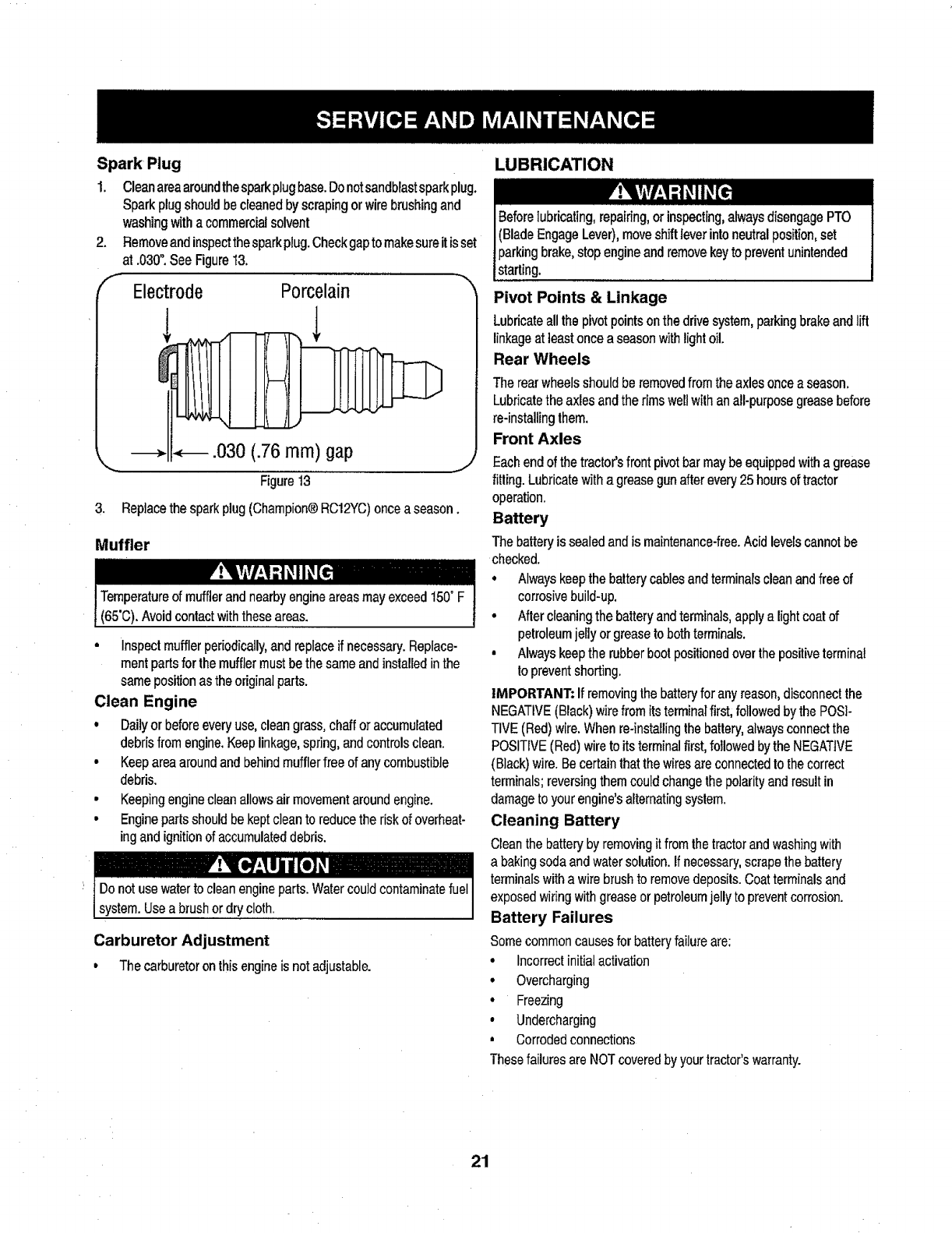
2. Removeandinspectthesparkplug.Checkgaptomakesureitisset
at.030".SeeFigure13.
Electrode Porcelain
.030 (.76 ram) gap
_,,,,, ...........
Figure13
3. Replacethesparkplug(Champion®RC12YC)onceaseason.
Muffler
i Temperatureof mufflerandnearbyengineareasmayexceed150"F
(65'C).Avoidcontactwiththeseareas.
•Inspectmuffler periodically,and replaceif necessary. Replace-
rnent parts for the muffler must bethe same and installedinthe
same position as the original parts.
Clean Engine
•Dailyor beforeeveryuse, clean grass, chaff or accumulated
debris from engine. Keeplinkage, spring, and controlsclean.
•Keep area around and behind muffler free of any combustibJe
debris.
• Keeping engineclean allowsair movementaroundengine.
• Enginepartsshould bekept cleanto reduce the riskof overheat-
ing and ignitionof accumulateddebris.
system.Useabrushordrycloth.
Carburetor Adjustment
• Thecarburetoronthisengineisnotadjustable.
LUBRICATION
Beforelubricating,repairing,orinspecting,alwaysdisengagePTO
(BladeEngageLever),moveshiftleverintoneutralposition,set
parkingbrake,stopengineandremovekeyto preventunintended
starting.
Pivot Points & Linkage
Lubricateallthepivotpointsonthedrivesystem,parkingbrakeandlift
linkageat leastonceaseasonwithlightoil.
Rear Wheels
Therearwheelsshouldberemovedfromtheaxlesonceaseason.
Lubricatethe axlesandtherimsweftwithanall-purposegreasebefore
re-instaUingthem.
Front Axles
Eachendof the tractor'sfront pivot bar maybe equipped witha grease
fitting. Lubricatewith a grease gun afterevery 25 hoursof tractor
operation.
Battery
The battery is sealed and is maintenance-free.Acid levels cannotbe
checked.
•Always keepthe battery cables and terminalscleanand free of
corrosive build-up.
•Nter cleaning the battery andterminals, apply a lightcoatof
petroleumjefly or grease to both terminals.
•Alwayskeep the rubberboot positionedover the positiveterminal
toprevent shorting.
IMPORTANT: If removingthe batteryfor any reason,disconnect the
NEGATIVE(Black) wire from itsterminalfirst, followedby the POSi-
TIVE(Red) wire. When re-installingthe battery,alwaysconnect the
POSITIVE (Red)wire to its terminalfirst, followed by the NEGATIVE
(Black)wire. Becertain that the wiresare connectedto the correct
terminals; reversingthem could changethe polarity and resultin
damage to your engine's aFternatingsyslem.
Cleaning Battery
Clean the battery by removingit fromthe tractorand washingwith
a baking soda and water solution, if necessary, scrapethe battery
terminals with a wirebrushto removedeposits. Coat terminalsand
exposed wiring with grease or petroleumjelly to prevent corrosion.
Battery Failures
Somecommoncauses for batteryfailureare:
•Incorrect initial activation
•Overcharging
• Freezing
•Undercharging
,Corrodedconnections
Thesefailures are NOTcovered by yourtractor'swarranty.
21

CLEANING THE ENGINE AND DECK
Anyfueloroilspilledonthemachineshouldbewipedoff promptly.Do
NOTallowdebristo accumulatearoundthecoolingfinsofthe engine
oronanyotherpartofthe machine.
IMPORTANT:Theuseof apressurewasherto cleanyourtractoris
NOTrecommended.Itmaycausedamageto electricalcomponents,
spindles,pulleys,bearingsortheengine.
A screwplugcanbefoundonyourtractor'sdecksurfaceas seenin
Fig.14.Thisplugcanbereplacedwithawaterporttobeusedas part
ofa separately-availabledeckwashsystem.
TheDeckWashSystemTM is usedto rinsegrassclippingsfromthe
deck'sundersideandpreventthe buildupofcorrosivechemicals.
NOTE:A deckwashsystemcanbepurchasedthroughtheretail
locationinwhichyoupurchasedthistractor.Formoreinformation,catl
1-800-4-MY+HOME@.
Figure 14
ADJUSTMENTS
,,J
Leveling the Deck
NOTE:Checkthetractor'stirepressurebeforeperforminganydeck
levelingadjustments.Referto TiresintheServicesectionof this
manualfor moreinformationregardingtirepressure.
Front To Rear
The front of the cutting deck is supported by a stabilizer bar that can
be adjusted to level the deckfrom front to rear.The front of the deck
should be between ¼-inch and3,_-inchlowerthan therear of the deck.
Adjust if necessary as follows:
1. With the tractor parkedon a firm, level surface,place the ]everfor
lifting the platformon the second to thetop notch (second
highest position)and rotatethe blade as close as possibleto the
discharge channel thatisparallel to the tractor.
2. Measurethedistancefromthefrontofthe bladetiptotheground
andtherearof thebladetipto theground.Thefirstmeasure-
menttakenshouldbebetween¼"and"_"lessthanthesecond
measurement.Determinetheapproximatedistancenecessaryfor
properadjustmentandproceed,ifnecessary,tothenextstep.
3. Locatetheflangelocknutonthefrontsideofthestabilizerbracket.
SeeFig.I5.
, Tightentheflangelocknutto raisethefrontofthedeck;
Loosentheflangelocknutto lowerthefrontofthedeck.
i)
f
Figure I5
Side to Side
If the cutting deck appearsto be mowing unevenly,a side to side
adjustmentcanbe performed.Adjust ifnecessary as follows:
1. Withthetractorparkedona firm,levelsurface,placethedecklift lever
inthe secondfrom the top notch (second highest position)and
rotateboth blades so that they are perpendicularwith the tractor.
2. Measurethe distance fromthe outsideof the teft blade tip tothe
groundand thedistance fromthe outside ofthe rightblade tipto
the ground. Bothmeasurementstaken should be equal. Ifthey're
not, proceedto the next step.
3. Loosen,butdo NOTremove,the hex capscrew onthe leftdeck
hangerbracket.See Fig.16.
4. Balancethedeckbyusingawrenchtoturntheadjustment gear(found
immediatelybehindthe hex capscrewjust loosened)clockwise/
up orcounterclockwise!down.The deck is propertybalanced
when both blade tip measurementstaken earlierare equal.
5. ReUghtenthe hex capscrewon theleft deck hanger bracketwhen
properadjustmentis achieved.
22
f
Hex CapScrew
_,.,,,,,,
Figure16
Seat Adjustment
Referto theAssembly section of thismanualfor seat adjustment
instructions.
Parking Brake Adjustment
J
Never attempttoadjustthebrakeswhilethe engineis running.Always
disengage PTO (bladeengage)lever,moveshift lever intoneutral
position,stopengineand removekeyto preventunintendedstarting.
Ifthetractordoesnotcometo acompletestopwhenthebrakepedal
iscompletelydepressed,orif thetractor'srearwheelscan rollwiththe
parkingbrakeapplied,thebrakeisinneedofadjustment.Contactthe
nearestSearsServiceCenterto haveyourbrakesproperlyadjusted.
TolocatethenearestParts&RepairServiceCenterortoschedule
service,contact1-800-4-MY-HOME®,
CUTTING DECK REMOVAL
To remove the cutting deck, proceed as follows:
1. Placethe PTO (Blade Engage) leverinthedisengaged (OFF)
position and engage the parkingbrake.
2. Lower the deck by movingthe deck lift lever into the bottom
notch on theright fender.
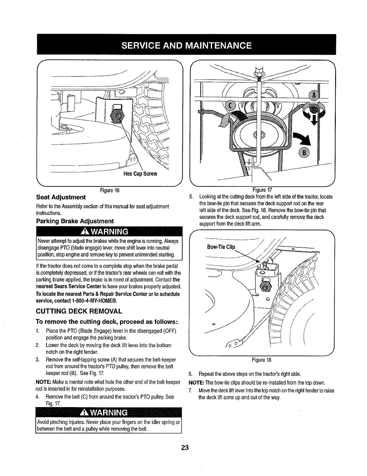
3. Removetheself-tappingscrew (A)that secures the belt-keeper
rodfrom around the tractor's PTOpulley,then remove thebelt
keeper rod (B), See Fig. 17.
NOTE; Make a mentalnote whathole the otherend of the belt-keeper
rod is inserted in for reinstallationpurposes.
4. Removethe belt(C) from around the tractor's PTO pulley.See
Fig. 17.
f
J
Figure17
Lookingat thecutting deck fromthe left side of the tractor,locate
the bow-tiepin thatsecures the deck support rod on the rear
left side of the deck.See Fig. 18.Removethe bow-tie pin that
securesthe deck support rod, and carefullyremovethe deck
support fromthe decklift arm.
Bow-TieClip J
....................... J
Figure 18
6. Repeatthe abovestepson the tractor's right side.
NOTE=The bow-tie clipsshould be re-installedfrom thetop down.
7. Movethe deck lift leverintothetop notchonthe rightfenderto raise
thedecklift arms up and out of the way.
23
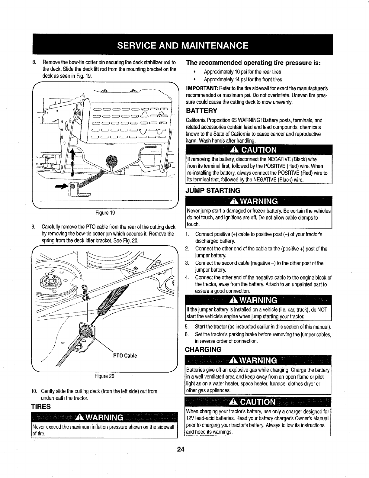
8. Removethe bow-tiecotter pin securingthe deck stabilizerrod to
the deck. Slidethe deck tiftrod from the mountingbracket onthe
deckas seen in Fig. 19.
f-..,
J
Figure 19
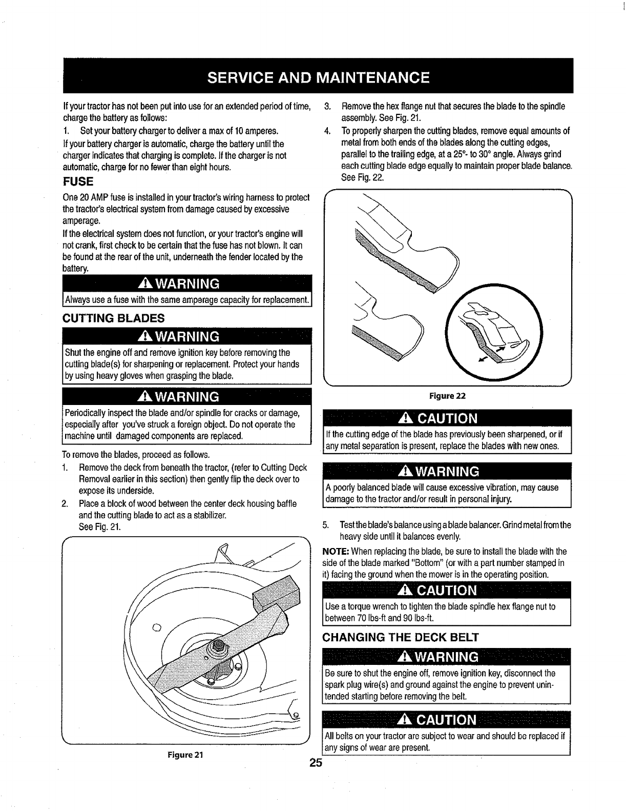
g, Carefullyremovethe PTO cablefrom the rearof the cutting deck
by removingthebow-tiecotterpinwhich securesit. Removethe
springfromthe deck idlerbracket.See Fig.20.
/
/
/
/
/
f
/
/
/PT0 Cable
Figure20
,J
10. Gentlyslidethecuttingdeck(fromtheleftside)outfrom
underneaththetractor,
TIRES
lF; lrir/ l'itT .dlI_
Neverexceedthe maximum inflationpressureshown on thesidewall
of t re.
The recommended operating tire pressure is:
,Approximately10psiforthereartires
° Approximately14psiforthefronttires
IMPORTANT:Refertothetiresidewallforexacttiremanufacturer's
recommendedormaximumpsi,Donotoverinflate,Uneventirepres-
surecouldcausethecuttingdecktomowunevenly.
Califomia Proposition65 WARNING!Battery posts, terminals,and
related accessoriescontain lead and leadcompounds, chemicals
knownto the State ofCalifornia to causecancer and reproductive
harm, Wash handsafter handling.
_OSITIVE (Red) wire to
its terminal first, followedby the NEGATIVE(Black)wire.
JUMP STARTING
1. Connectpositive (+)cableto positive post(+) of your tractor's
dischargedbattery.
2. Connectthe other end ofthe cable to the (positive+) postof the
jumper battery.
3. Connectthe second cable(negative-) tothe other post of the
jumper battery.
4. Connectthe otherend of the negativecable to the engine block of
the tractor,away from the battery.Attach to an unpaintedpart to
assurea good connection.
Ifthejumper battery isinstalled ona vehicle(i.e. car, truck), do NOT
start the vehicle'senginewhenjump startingyour tractor.
5. Start the tractor (as instructedearlierin thissection of thismanual).
6. Set the tractor'sparking brakebefore removing thejumper cables,
in reverseorder of connection.
CHARGING
IBatteries giveoff an explosivegas while charging.Chargethe batteryI
in a wellventilatedareaand keepawayfrom an open flame or pilot I
light as on a waterheater,space heater,furnace, clothes dryeror I
other gasappliances. I
24
Ifyourtractorhasnotbeenputintouseforanextendedperiodof time, 3.
chargethebatteryasfollows:
1. Setyourbatterychargerto delivera maxof 10amperes. 4.
Ifyourbatterychargerisautomatic,chargethe batteryuntilthe
chargerindicatesthatchargingiscomplete,tfthechargeris not
automatic,chargefornofewerthaneighthours.
FUSE
One20AMPfuseisinstalledinyourtractor'swiringharnesstoprotect _'-
thetractor'selectricalsystemfromdamagecausedbyexcessive
amperage.
if theelectricalsystemdoesnotfuncfion,oryourtractor'senginewill
notcrank,firstcheckto becertainthatthefusehasnotblown,it can
befoundatthe rearof theunit,underneaththefenderlocatedbythe
battery.
CUTTING BLADES
Shuttheengineoffandremoveignitionkeybeforeremovingthe
cuttingblade(s)forsharpeningorreplacement.Protectyourhands
byusngheavygoveswhengraspngthebado.
Removethe hexflangenutthatsecuresthebladeto thespindle
assembly.SeeFig.21.
Toproperlysharpenthecuttingblades,removeequalamountsof
metalfrombothendsof thebladesalongthecuttingedges,
paralleltothetrailingedge,at a25°to 30° angle.Alwaysgrind
eachcuttingbladeedgeequallyto maintainproperbladebalance.
SeeFig.22.
Figure 22
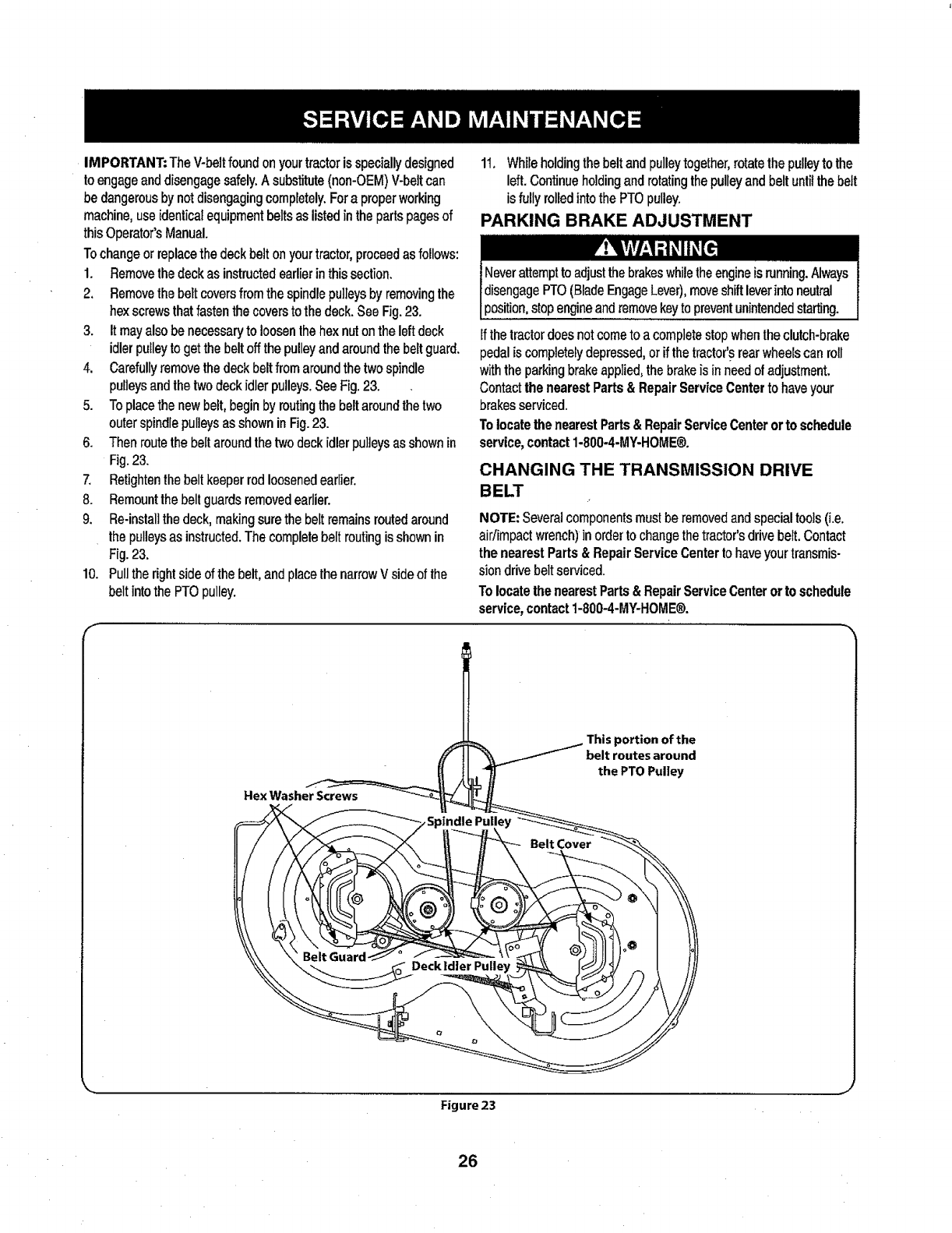
Toremovetheblades,proceedas follows.
1. Removethedeckfrombeneaththetractor,(refertoCuttingDeck
Removalearlierinthissection)thengentlyflip thedeckoverto
exposeitsunderside.
2. Placea blockofwoodbetweenthecenterdeckhousingbaffle
andthe cuttingbladeto actasa stabilizer.
SeeFig.21.
,,, ......,..........
Figure 21
5. Testthe blade'sbalanceusingablade balancer.Grindmetalfromthe
heavy side until it balancesevenly.
NOTE; When replacingthe blade, be sureto install the blade with the
side of the blade marked "Bottom" (or witha part number stamped in
it) facingthe groundwhenthe mower is in the operating position.
Use a torque wrenchto tightentheblade spindrehex flangenut to
between70 Ibs-ftand 90 Ibs-ft.
CHANGING THE DECK BELT
Allbeltsonyourtractoraresubjecttowearandshouldbereplacedif
anysignsof weararepresent.
25
IMPORTANT:TheV-beltfoundonyourtractorisspeciallydesigned
toengageanddisengagesafely.Asubstitute(non-OEM)V-beltcan
bedangerousbynotdisengagingcompletely.Fora properworking
machine,useidenticalequipmentbeltsas listedinthepartspagesof
thisOperator'sManual.
Tochangeorreplacethedeckbeltonyourtractor,proceedasfollows:
1. Removethedeckas instructedearlierinthissection.
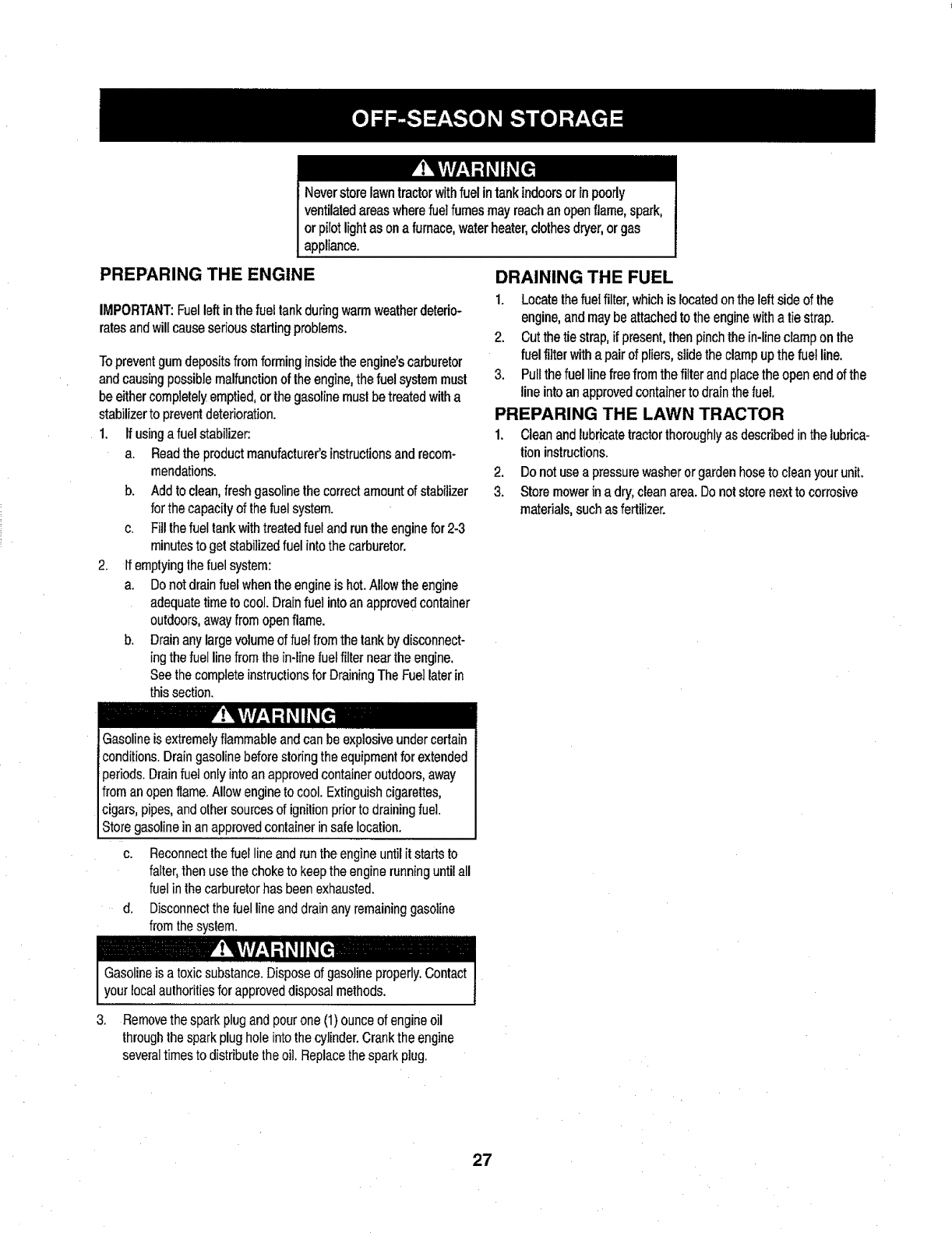
2. Removethe beltcoversfromthe spindlepulleysbyremovingthe
hexscrewsthatfastenthecoversto thedeck.SeeFig.23.
3. It mayalsobenecessaryto loosenthehexnutontheleftdeck
idlerpulleytogetthe beltoffthepulleyandaroundthebeltguard.
4. Carefullyremovethedeckbeltfromaroundthetwospindle
pulleysandthetwodeckidlerpulleys.SeeFig.23.
5. Toplacethenewbelt,beginby routingthebeltaroundthetwo
outerspindlepulleysasshownin Fig.23.
6. Thenroutethebeltaroundthetwodeckidlerpulteysasshownin
Fig.23.
7. Retightenthebeltkeeperrodloosenedearlier.
8. Remountthebeltguardsremovedearlier.
9. Re-installthedeck,makingsurethebeltremainsroutedaround
the pulleysas instructed.Thecompletebeltroutingis shownin
Fig.23.
10. Pulltherightsideofthebelt,andplacethenarrowVsideof the
beltintothe PTOpulley.
1t. Whileholdingthebeltandpulleytogether,rotatethepulleytothe
left.Continueholdingandrotatingthepulleyandbeltuntilthebelt
isfullyrolledintothePTOpulley.
PARKING BRAKE ADJUSTMENT
Neverattempttoadjustthebrakeswhiletheengineisrunning.Always
disengagePTO(BladeEngageLever),moveshiftleverintoneutral
position,stopengineandremovekeytopreventunintendedstarting.
Ifthetractordoesnotcometo a completestopwhentheclutch-brake
pedaliscompletelydepressed,orifthetractor'srearwheelscanroll
withtheparkingbrakeapplied,thebrakeisinneedofadjustment.
Contactthe nearestParts&RepairServiceCenterto haveyour
brakesserviced.
TolocatethenearestParts& RepairServiceCenterortoschedule
service,contact1-800-4-MY-HOME®.
CHANGING THE TRANSMISSION DRIVE
BELT
NOTE:Severalcomponentsmustberemovedandspecialtools(i.e.
aidimpactwrench)inorderto changethetractor'sdrivebelt.Contact
the nearestParts&RepairServiceCentertohaveyourtransmis-
siondrivebeltserviced.
TolocatethenearestParts&RepairServiceCenterortoschedule
service,contact1-800-4-MY-HOME®.
_This portion of the
/(/" !l "_,,_..._I_ belt routes around
--'--'-_--'-'----_ _ /_'_ the PTO Pul|ey
He_ _/spier__ndie pul,ey
Figure 23
26
Neverstorelawntractorwithfuelintankindoorsorinpoorly
ventilatedareaswherefuelfumesmayreachanopenflame,spark,
orpilotlightasonafurnace,waterheater,clothesdryer,orgas
appliance,
PREPARING THE ENGINE
IMPORTANT:Fuelleftinthefueltankduringwarmweatherdeterio-
ratesandwillcauseseriousstartingproblems.
To preventgum deposits from forming inside the engine'scarburetor
and causing possible malfunctionof the engine,the fuel systemmust
be eithercompletelyemptied, or the gasoline must be treated with a
stabilizerto prevent deterioration.
1. If usinga fuel stabilizer:
a. Readthe product manufacturer'sinstructionsand recom-
mendations.
b. Add to clean,freshgasoline the correct amountof stabilizer
for the capacity of the fuelsystem.
c. Fillthe fuel tankwithtreated fuel and run the enginefor 2-3
minutesto get stabilizedfuel intothe carburetor.
2. If emptyingthe fuel system:
a. Donot drain fuel whentheengineis hot.Allow the engine
adequatetime to cool. Drain fuel into an approved container
outdoors, awayfrom open flame.
b. Drainany large volumeof fuelfrom the tank by disconnect-
ing the fuel line from the in-line fuelfilter neartheengine.
See the complete instructionsfor Draining The Fuel laterin
this section.
DRAINING THE FUEL
1. Locatethefuel filter,whichis locatedon theleftside ofthe
engine, and maybe attached to the enginewith a tie strap.
2, Cut the tie strap, if present,then pinchthe in-lineclamp on the
fuelfilter with a pairof pliers, slide the clamp upthe fuel line.
3. Pull the fuelline free from the filter and placethe open end of the
line into an approvedcontainerto drainthe fuel.
PREPARING THE LAWN TRACTOR
1, Cleanand lubricatetractor thoroughly as described in the lubrica-
tioninstructions.
2. Do not usea pressurewasher or garden hoseto clean your unit.
3. Storemowerin a dry;clean area. Do not storenext to corrosive
materials,such as fertilizer.
-,.-,
!Gasolineis extremelyflammableand can be explosiveundercertain
_conditions. Dramgasoline before storingthe equipment for extended
_periods. Drainfuet only intoan approvedcontainer outdoors, away
from an open flame. Allowengine to cool. Extinguishcigarettes,
cigars, pipes, and othersources of ignition priorto drainingfuel.
Store gasolinein an approvedcontainer in safelocation.
c. Reconnectthe fuel line and run theengine until itstarts to
falter,then usethe choketo keep the engine runninguntil all
fuel in thecarburetorhas been exhausted.
d. Disconnectthe fuel line and drain any remaininggasoline
from the system.
I i .....
Gasolineis a toxic substance. Disposeof gasoline properly.Contact
your localauthorities for approved disposal methods.
3. Removethe spark plugand pourone (1)ounce ofengine oil
throughthespark plughole intothe cylinder. Crankthe engine
several timesto distribute theoil. Replacethe spark plug.
27
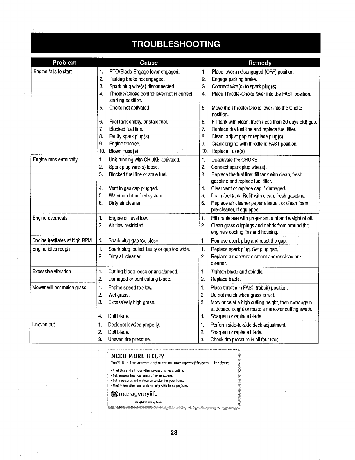
Enginefailsto start
Enginerunserratically
1. PTOIBladeEngageleverengaged,
2, Parkingbrakenotengaged.
3. Sparkplugwire(s)disconnected.
4. ThrutttelChokecontrollevernotincorrect
startingposition,
5, Chokenotactivated
6, Fueltankempty,orstalefuel.
7. Blockedfuelline.
8, Faultysparkplug(s),
9, Engineflooded.
!0, BlownFuse(s)
t. UnitrunningwithCHOKEactivated,
2, Sparkplugwire(s)loose.
3. Blockedfuel lineorstalefuel
4. Vent in gascap plugged.
5. Wateror dirt in fuel system.
6. Dirty air cleaner.
Engineoverheats t. Engineoillevel low. 1.
2. Air flow restricted. 2.
Enginehesitatesat high RPM I. Sparkplug gaptoo close. 1.
Engineidles rough 1. Spark plugfouled, faulty or gaptoo wide. 1.
2. Dirty air cleaner. 2.
Excessivevibration
Mowerwill not mulch grass
Uneven cut
1. Cutting blade loose or unbalanced.
2. Damagedor bent cutting blade.
1. Enginespeed too low.
2. Wetgrass.
3. Excessivelyhighgrass.
4, Dullblade.
1. Decknotleveledproperly.
2. Dullblade.
3. Uneventirepressure.
1. Placeleverindisengaged(OFF)position,
2. Engageparkingbrake.
3, Connectwire(s)to sparkplug(s),
4, PlaceThrottle/ChokeleverintotheFASTposition.
5. Movethe Throttle/Chokelever intothe Choke
position.
6. Fill tank withclean, fresh (less than 30 days old) gas.
7, Replacethe fuel line and replacefuel filter.
8. Clean,adjust gap or replaceplug(s).
9. Crankengine withthrottle in FASTposition.
10. ReplaceFuse(s)
1. Deactivatethe CHOKE.
2. Connectspark plugwire(s).
3. Replacethe fuelline; fill tank with clean,fresh
gasolineand replace fuelfilter.
4. Clear vent orreplace cap ifdamaged.
5. Drain fueltank. Refill withclean, fresh gasoline.
6. Replace aircleaner paper elementor cleanfoam
pro-cleaner, ifequipped.
Firlcrankcasewith proper amountand weighi oi"oill
Cleangrass clippings and debrisfrom aroundthe
engine'scooling finsand housing.
Removespark plug and resetthe gap.
Replacespark plug. Set pluggap.
Replaceair cleaner elementand/or cleanpro-
cleaner.
I. Tighten blade and spindle.
2. Replaceblade.
1. Placethrottle in FAST(rabbit) position.
2. Do notmulch when grass is wet.
3. Mow once at a high cutting height, then mow again
at desiredheight or make a narrowercutting swath.
4. Sharpen or replaceblade.
1. Perform side-to-sidedeck adjustment.
2. Sharpenor replaceblade.
3. Check tire pressurein a]l four tires.
NEED MORE HELP? _i_
¥m:_I fi_td the an,_werand mm+e m_ mazl_emyUfe,com -for free! _:
•Hnd th_s a_d a[[ your other produ_ manuals ontine. _i
i" Get answersfrom our team of home experts. _.
:i " Get apersonalized maintenance plan for your ho_ae. _i
', " F_nd information and tools to help with home projects.
28
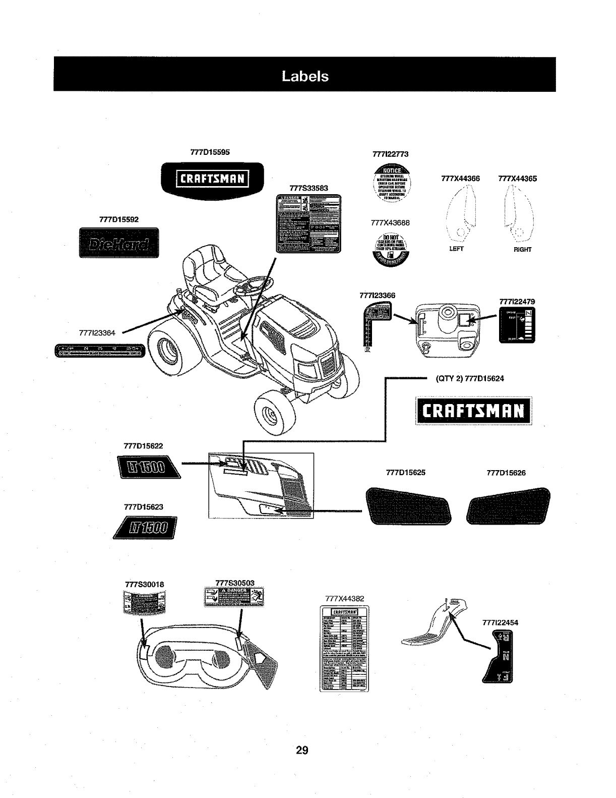
777D15592
777D15595
777S33583
777122773
i ........m,=--,!
777X43688
_cmt_m!cmE
ihim _o%k-'m.lu_
777X44366 777X44365
LEFT RIGHT
777123366 777122479
777123364
(QTY2)777D15624
777D15622
777D15623
777D15625 777D15626
777S30018
777X44382
29
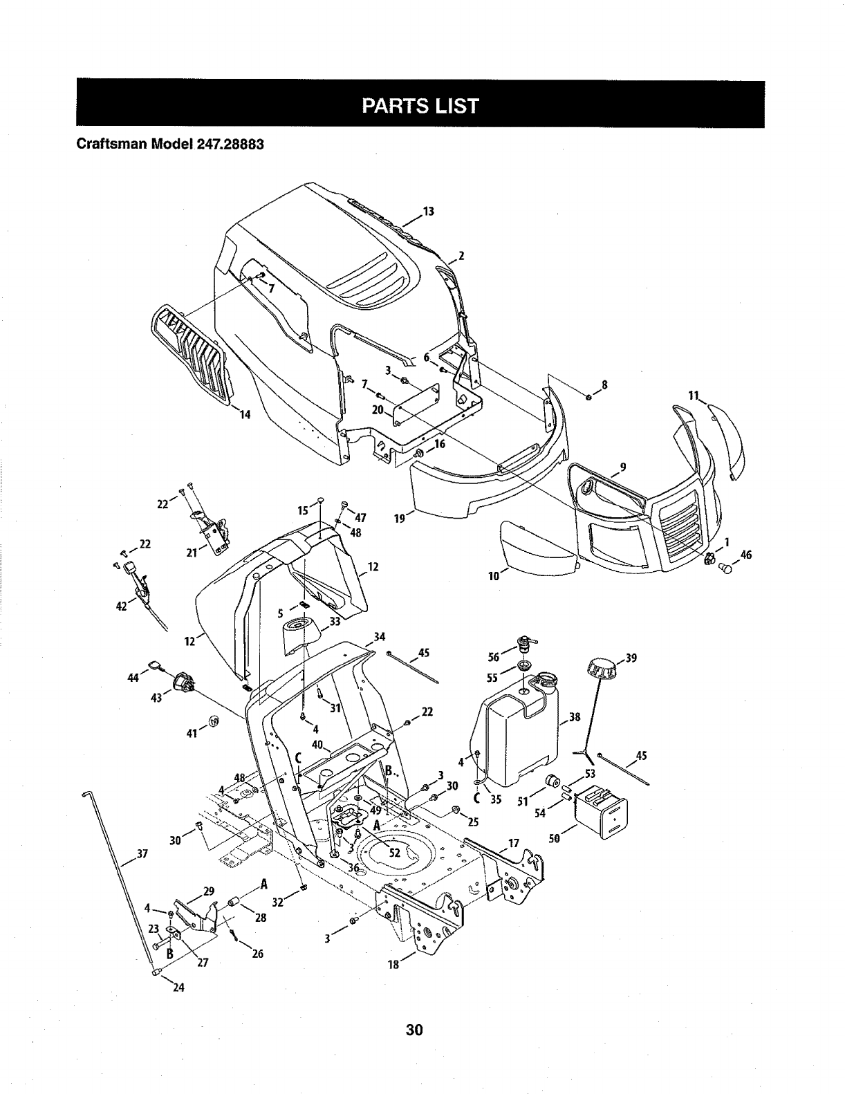
Craftsman Model 247.28883
12 10
146
34
3O
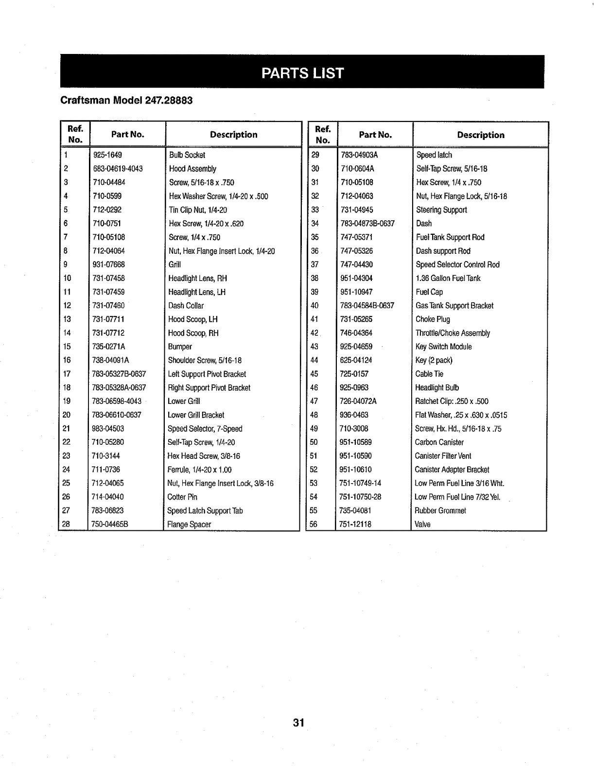
CraftsmanModel247,28883
Ref.
No.
1
2
3
4
5
6
7
8
9
10
11
12
13
I4
15
16
17
18
19
20
21
22
23
24
25
28
27
28
Part No.
925-1649
683-04619-4043
710-04484
710-0599
712-0292
710-0751
710-05108
712-04064
93t-07668
731-07458
731-07459
731-07460
731-07711
731-07712
735-0271A
738-04091A
783-05327B-0637
783-05328A-0637
783-06598-4043
783-06610-0637
983-04503
710-05280
710,3144
711-0736
712-04065
714-04040
783-06823
750,04465B
,J Description
BulbSocket
HoodAssembly
Screw,5116-t8x .750
HexWasherScrew,t/4-20x .500
TinClipNut,1/4-20
HexScrew,1/4-20x .620
Screw,1/4x .750
Nut,HexFlangeInsertLock,I/4-20
Grill
HeadlightLens,RH
HeadlightLens,LH
DashCollar
HoodScoop,LH
HoodScoop,RH
Bumper
ShoulderScrew,5/16-18
LeftSupportPivotBracket
RightSupportPivotBracket
LowerGrill
LowerGriflBracket
SpeedSelector,7-Speed
Self-TapScrew,1/4-20
HexHeadScrew,3/8-16
Ferrule,I/4-20x 1.00
Nut,HexFlangeInsertLock,3/8-16
CotterPin
SpeedLatchSupportTab
FlangeSpacer
.o,.i
No. J Part No.
29 783-04903A
30 7t0-0604A
31 710-05108
32 712-04063
33 731-04945
34 783-04873B-0637
35 747-05371
36 747-05326
37 747-04430
38 951-04304
39 951-10947
40 783-04584B-0637
41 i73t-05265
42 1746-04364
43 1925-04659
44 1625°04124
45 t725-0157
46 1925-0963
47 1726-04072A
48 1936-0463
49 1710-3008
50 J951-10589
51 1951-10590
52 1951-I0610
53 175t-10749-14
54 1751-10750-28
55 J735-04081
56 1751-12118
j Description .....
Speedlatch
Self-TapScrew,5/I6-t8
HexScrew,1/4x .750
Nut,HexFlangeLock,5116-18
SteeringSupport
Dash
FuelTankSupportRod
DashsupportRod
SpeedSelectorControJRod
1.36GallonFuelTank
FuelCap
GasTankSupportBracket
ChokeRug
Throttle/ChokeAssembly
KeySwitchModule
Key(2pack)
CableTie
HeadlightBulb
RatchetClip:.250x.500
FiatWasher,.25x.630x .0515
Screw,Hx.Hd.,5/16-18x .75
CarbonCanister
CanisterFitterVent
CanisterAdapterBracket
LowPermFuelLine3/16Wht.
LowPermFuelLine7/32Yet.
RubberGrommet
Valve
31
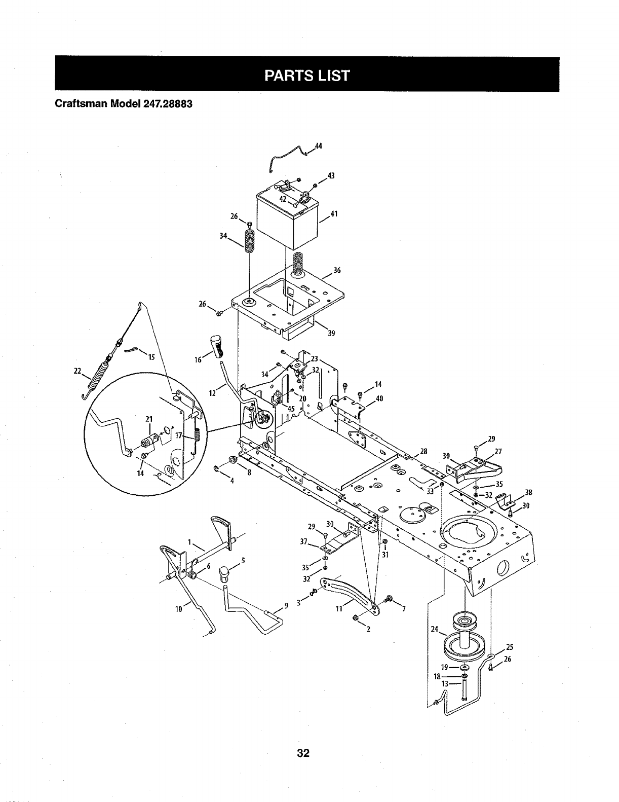
CraftsmanModel247,28883
22
32
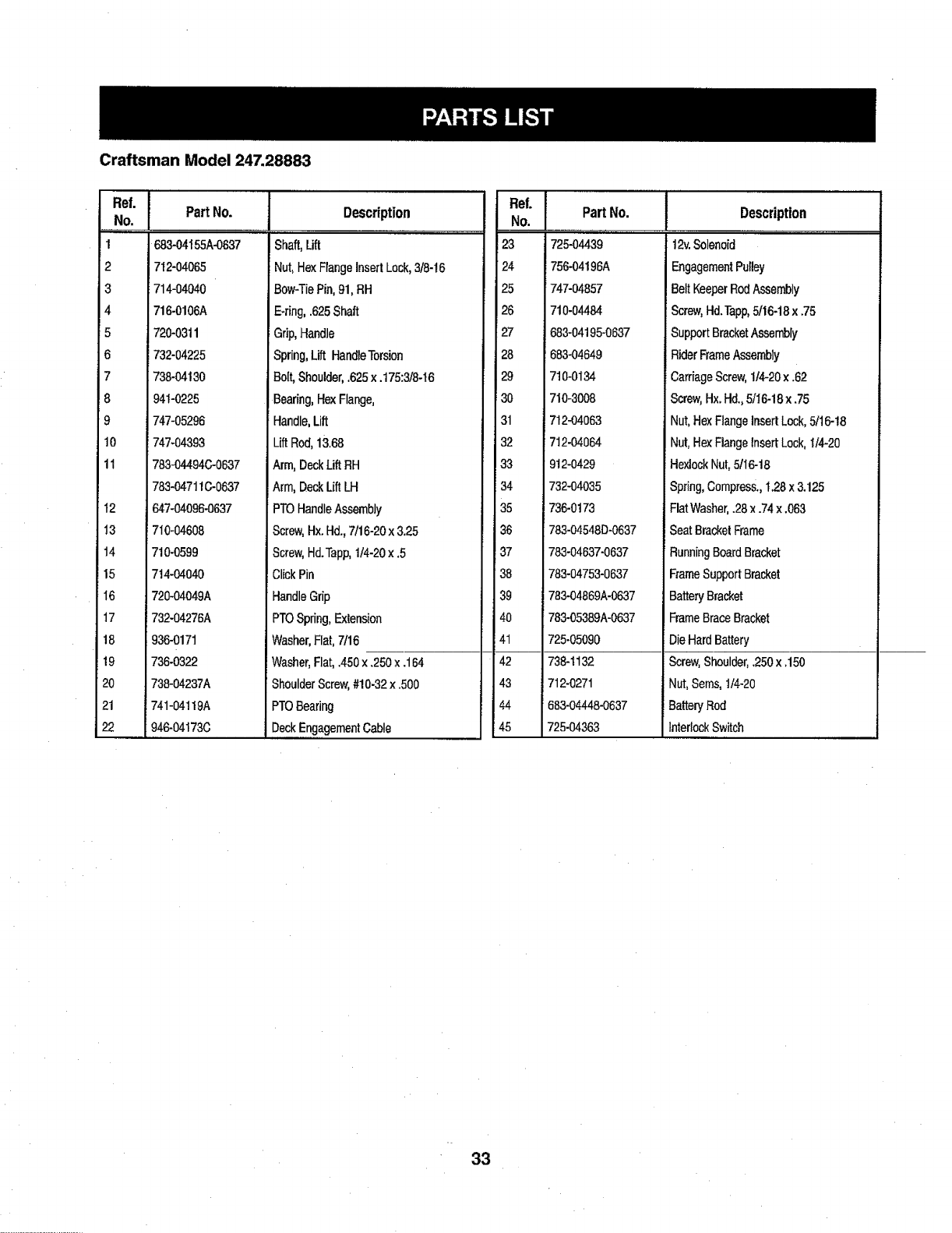
CraftsmanModel247.28883
Ref. i....
.N°',,,,I
1
2
3
4
5
6
7
_8
9
t0
11
12
13
14
15
I6
17
18
19
2O
21
22
Part No.
683-04155A-0637
712-04065
714-04040
716-0106A
720-0311
732-04225
738-04130
941-0225
747-05296
747-04393
783-04494(;-0837
783-047110-0637
647-04096-0637
710-04608
710-0599
714-04040
720-04049A
732-04276A
936-0171
736-0322
738-04237A
741-04119A
946-04173C
Description
Shaft,Lift
Nut,HexFlangeInsertLock,3t8-16
Bow-TiePin,91,RH
E-ring,.625Shaft
Grip,Handle
Spring,Lift HandleTorsion
Bert,Shoulder,.625x .175:3/8-t6
Bearing,HexFlange,
Handle,Lift
LiftRod,13,68
Arm, DeckLift RH
Arm,DeckLift LH
PTOHandleAssembly
Screw,Hx.Hd.,7/16-20x3.25
Screw,Hd.Tapp,1/4-20x.5
ClickPin
HandleGrip
PTOSpring,Extension
Washer,Flat,7t16
j Washer,Flat,.450x250 x.164
ShoulderScrew,#10-32x .500
PTOBearing
DeckEngagementCable
"e'r
No.
23
24
25
26
27
28
29
30
31
32
33
34
35
36
37
38
39
4O
41
42
43
44
'=45
Part No.
725-04439
756-04196A
747-O4857
710-04484
683-04195-0637
683-04649
7t0-0134
710-3008
712-04063
712-04064
9!2-0429
732-04035
736-0!73
783-04548D-0637
783-04637-0637
783-04753-0637
783-04869A-0637
783-05389A-0637
725-05090
738-1132
712-0271
683-04448-0637
725-04363
Description
,,, ,,,.....
12v.Solenoid
EngagementPulley
BeltKeeperRodAssembly
Screw,Hd.Tapp,5/16-18x .75
SupportBracketAssembly
RiderFrameAssembly
CarriageScrew,1/4-20x .62
Screw,Hx.Hd.,5/I6-18x.75
Nut,HexFlangeInsertLock,5/16-18
Nut,HexFlangeinsertLock,1/4-20
HexlockNut,5/I6-18
Spring,Compress.,1.28x3.125
FlatWasher,.28x.74x.063
SeatBracketFrame
RunningBoardBracket
FrameSupportBracket
BatteryBracket
FrameBraceBracket
DieHardBattery
Screw,Shoulder,.250x .150
Nut,Serns,1/4-20
BatteryRod
InterlockSwitch
33

Craftsman Model 247.28883
25
22
t32
34
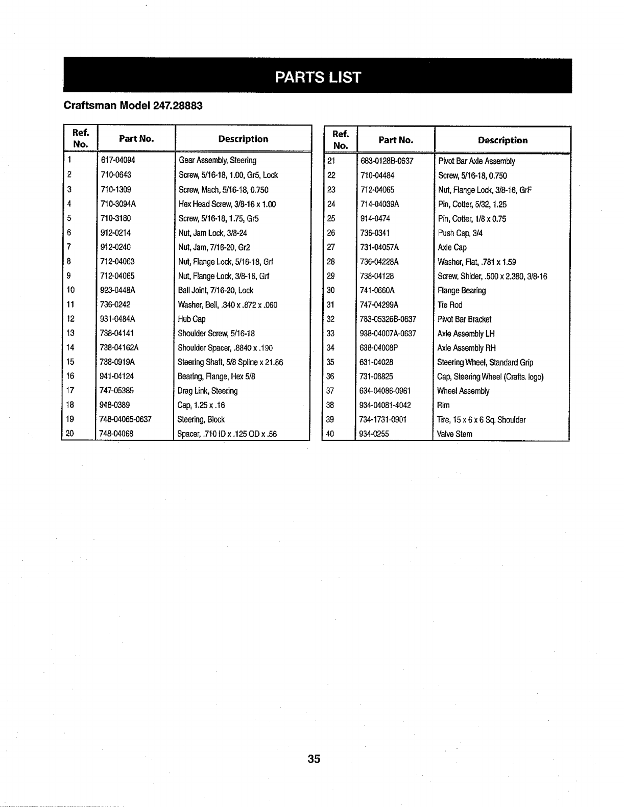
Craftsman Model 247.28883
"°'!
No.
1
2
3
4
5
6
7
8
9
10
11
!2
I3
14
15
16
17
t8
19
20
Part No.
617-04094
710-0643
710-1309
710-3094A
710-3180
912-0214
912-0240
712-04063
712-04065
923-0448A
736-0242
93t-0484A
738-04141
738-04162A
738-0919A
941-04124
747-05385
948-0389
_748-04065-0637
748-04068
Description
.........................,,,
............_ r
GearAssembly,Steering
Screw,5t16-18,1.00,Gr5,Lock
Screw,Mach,5/16-t8,0.750
HexHeadScrew,3/8-16x 1.00
Screw,5/16-18,1.75,Gr5
Nut,JamLock,3/8-24
Nut,Jam,7116-20,Gr2
Nut,FlangeLock,5/16-18,Grf
i Nut,FlangeLock,3/8-16,Grf
BallJoint,7/16-20,Lock
Washer,Bell,340 x .872x.060
HubCap
ShoulderScrew,5/16-18
ShoulderSpacer,.8840x .190
SteeringShaft,5/8Sp]inex21.86
Bearing,Flange,Hex5/8
DragLink,Steedng
Cap,t.25x .16
Steering,Block
Spacer,.710]Dx.125ODx .56
No.
21
22
23
24
25
26
27
!28
29
30
31
32
33
34
35
36
37
38
39
40
Part No. Description
PivotBarAxleAssembly
Screw,5116-18,0.750
Nut,FlangeLock,3/8-16,GrF
Pin,Cotter,5t32,1.25
Pin,Cotter,1/8x0.75
PushCap,3/4
AxleCap
Washer,Flat,.781x 1.59
Screw,Shlder,500 x2.380,3/8-I6
RangeBearing
TieRod
PivotBarBracket
AxleAssemblyLH
AxleAssemblyRH
SteeringWheel,StandardGrip
iCap,SteeringWheel(Crafts.logo)
WheelAssembly
Rim
]]re,15x 6x 6 Sq.Shoulder
ValveStem
683-0!28B-0637
710-04484
712-04065
i714-04039A
i914-0474
i736-0341
731-04057A
_736-04228A
738-04128
741-0660A
747-04299A
783-05326B-0637
938-04007A-0637
638-04008P
631-04028
731-06825
634-04086-0961
934-04081-4042
734-1731-0901
934-0255
35
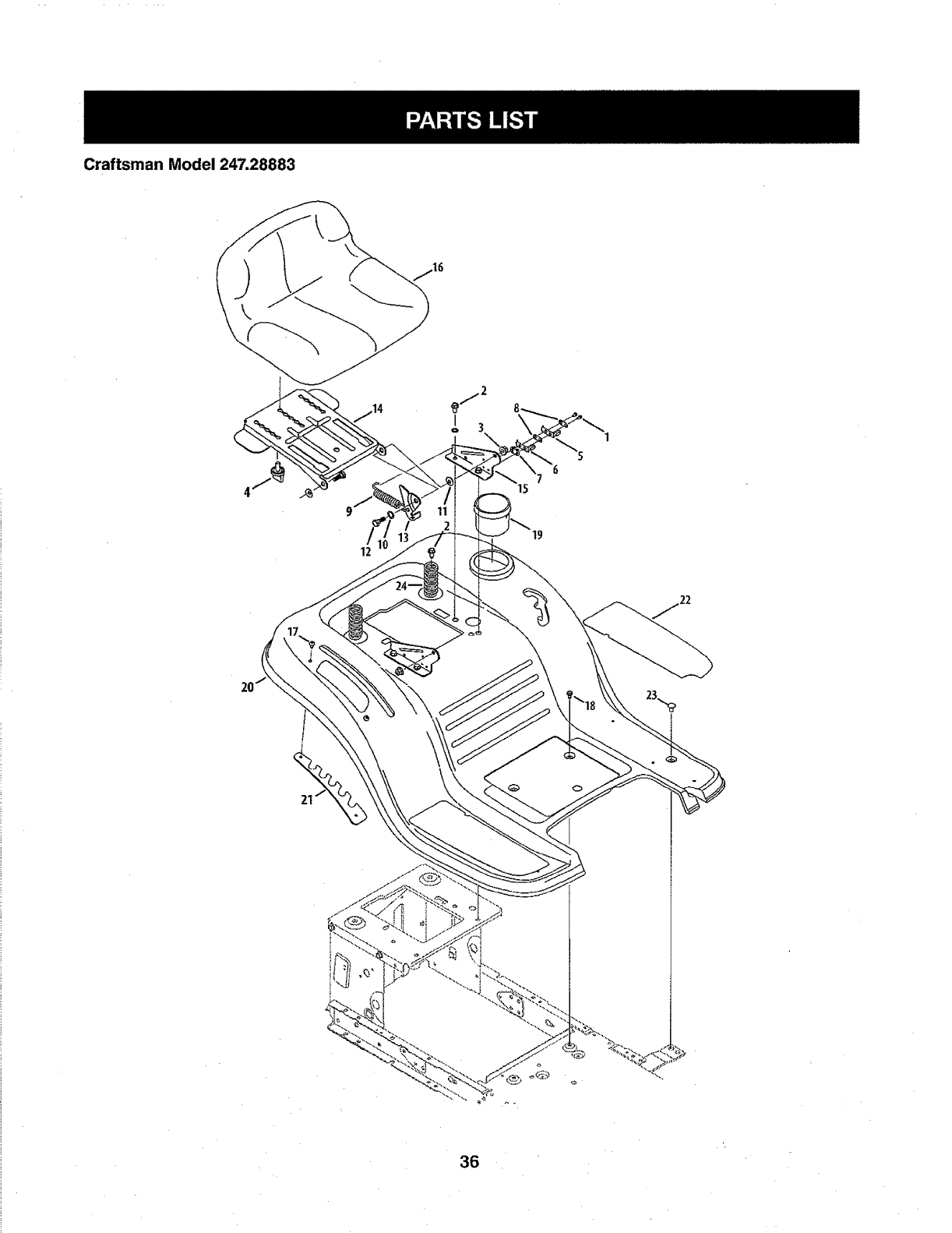
Craftsman Model 247.28883
I
o3
12
36
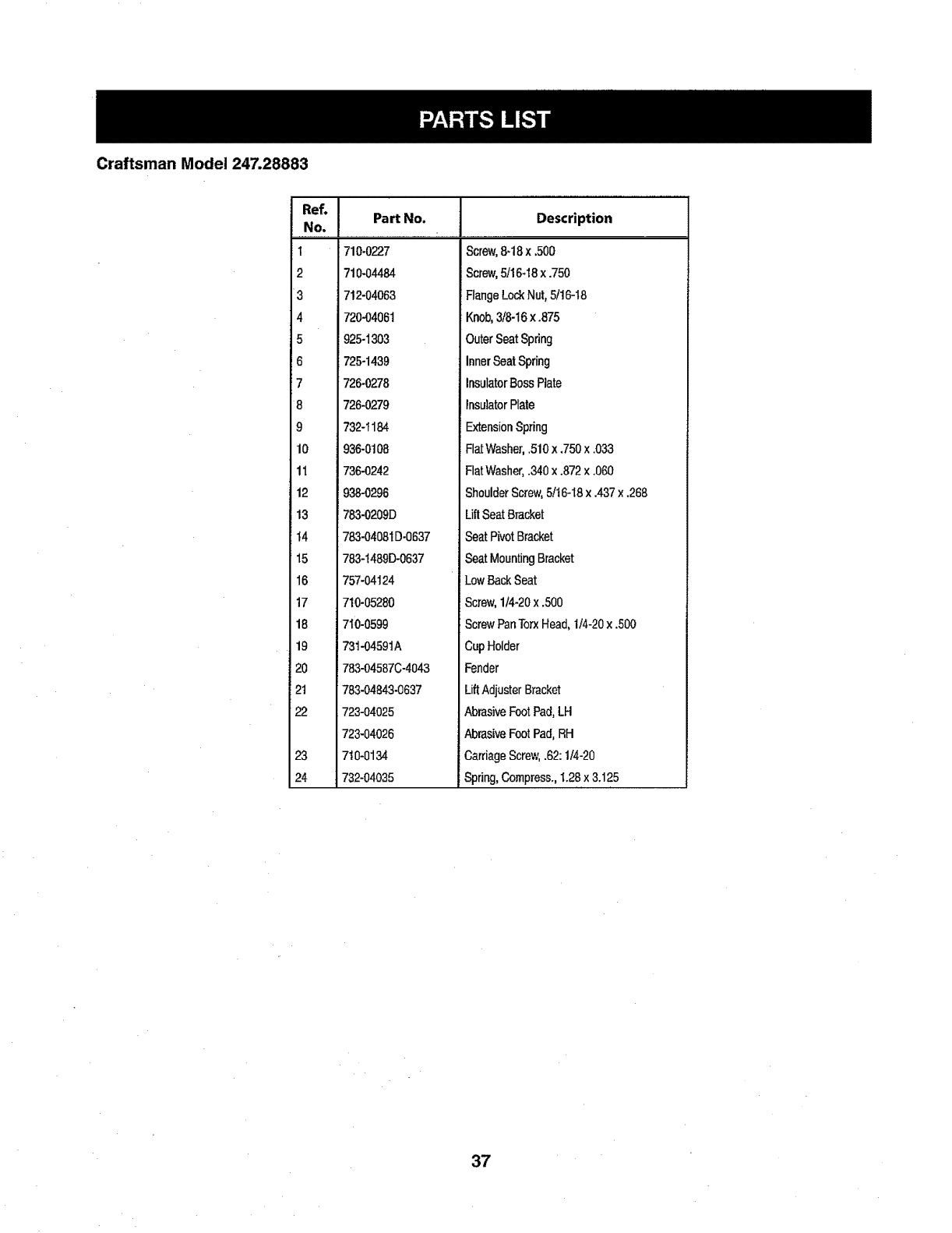
Craftsman Model 247.28883
"e'-r
NO,
t
2
3
4
5
6
7
8
9
10
11
12
13
t4
15
16
17
18
19
120
21
22
23
24
Part No. Description
710-0227
710-04484
712-04063
720-04061
Screw,8-18x ,500
iScrew,5/16-18x .750
FlangeLockNut,5t16-18
Knob,3/8-16x .875
925-1303
725-1439
726-0278
726-0279
732-1184
936-0108
736-O242
938-0296
783-0209D
783-04081D-0637
783-1489D-0637
757-04124
710-05280
710-0599
731-04591A
783-04587C-4043
783-04843-0637
723-04025
723-04026
710-0134
732-04035
OuterSeatSpring
InnerSeatSpring
InsulatorBossPlate
InsulatorPlate
ExtensionSpring
FlatWasher,.510x ,750x .033
FlatWasher,.340x.872x.060
ShoulderScrew,5/t6-I8 x .437x .268
LiftSeatBracket
SeatPivotBracket
SeatMountingBracket
LowBackSeat
Screw,114-20x.500
ScrewPanTorxHead,1/4-20x.500
CupHolder
Fender
LiftAdjusterBracket
AbrasiveFootPad,LH
AbrasiveFootPad,RH
CarriageScrew,.62:1/4-20
Spring,Compress.,1.28x3.125
37
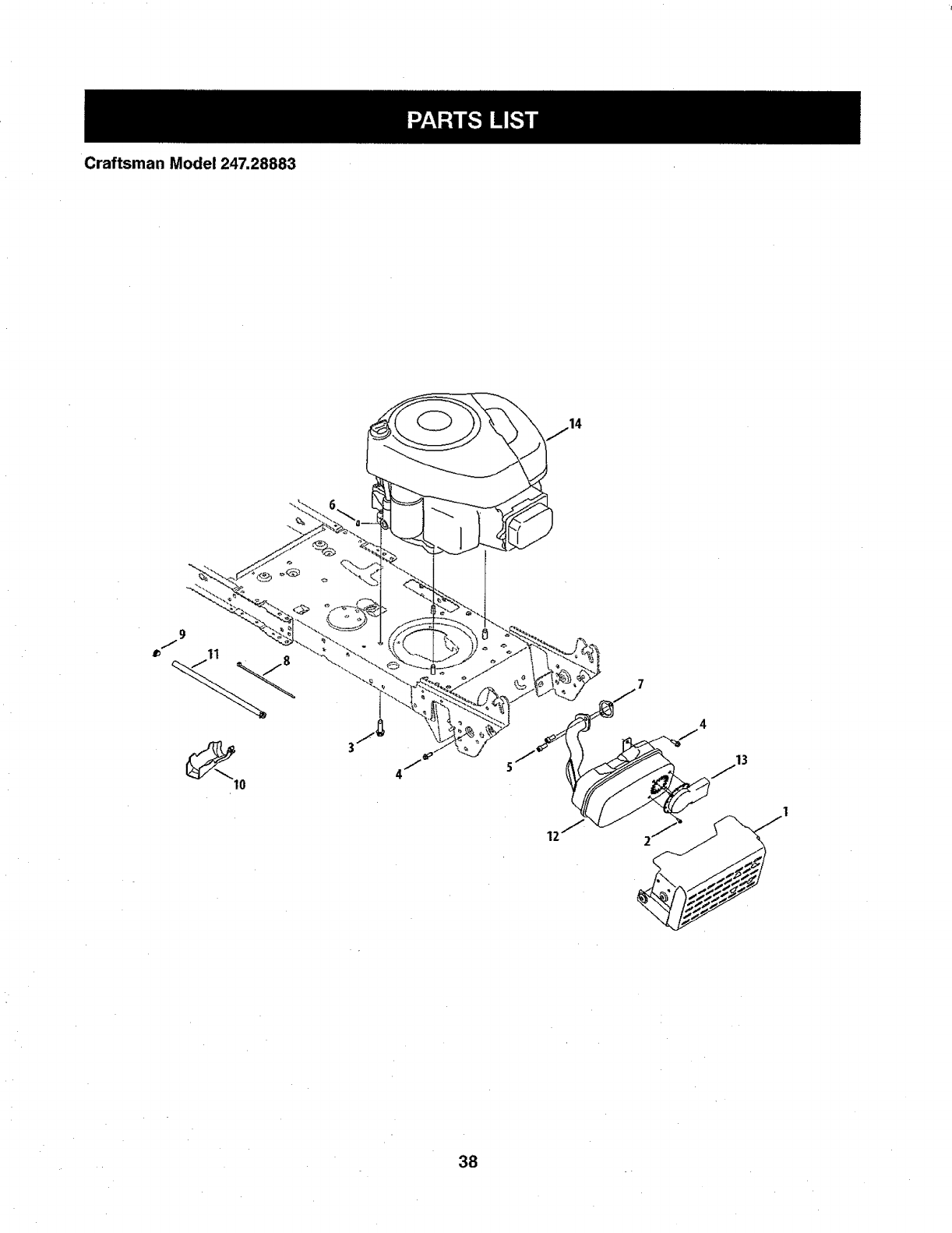
Craftsman Model 247.28883
11
10
4
13
38
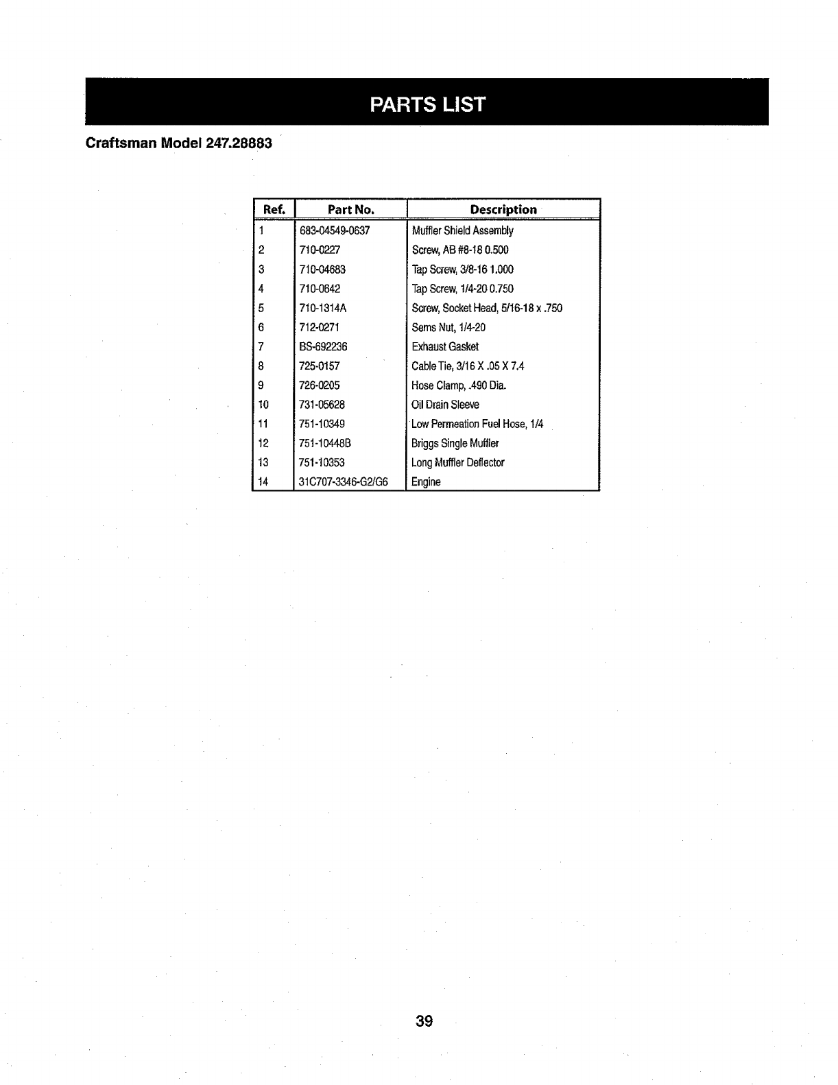
Craftsman Model 247.28883
Ref, I Part No.
1 683-04549-0637
2 710-0227
3 710-04683
4 710-0642
5 710-13t4A
6 712-027I
7 BS-692236
8 725-0157
9 726-0205
t0 731-05628
11 751-10349
12 751-10448B
13 751-10353
I4 31C707-3346-G2!G6
Description
MufflerShieldAssembly
Screw,AB #8-I80.500
TapScrew,3/8-161,000
TapScrew,tt4-200.750
Screw,SocketHead,5/t 6-18x .750
SernsNut,1/4-20
ExhaustGasket
CableTie,3/16X.05X7,4
HoseCIamp,.490Dia.
OilDrainSleeve
Low PermeationFuelHose,I/4
BriggsSingleMuffler
LongMufflerDeflector
Engine
39
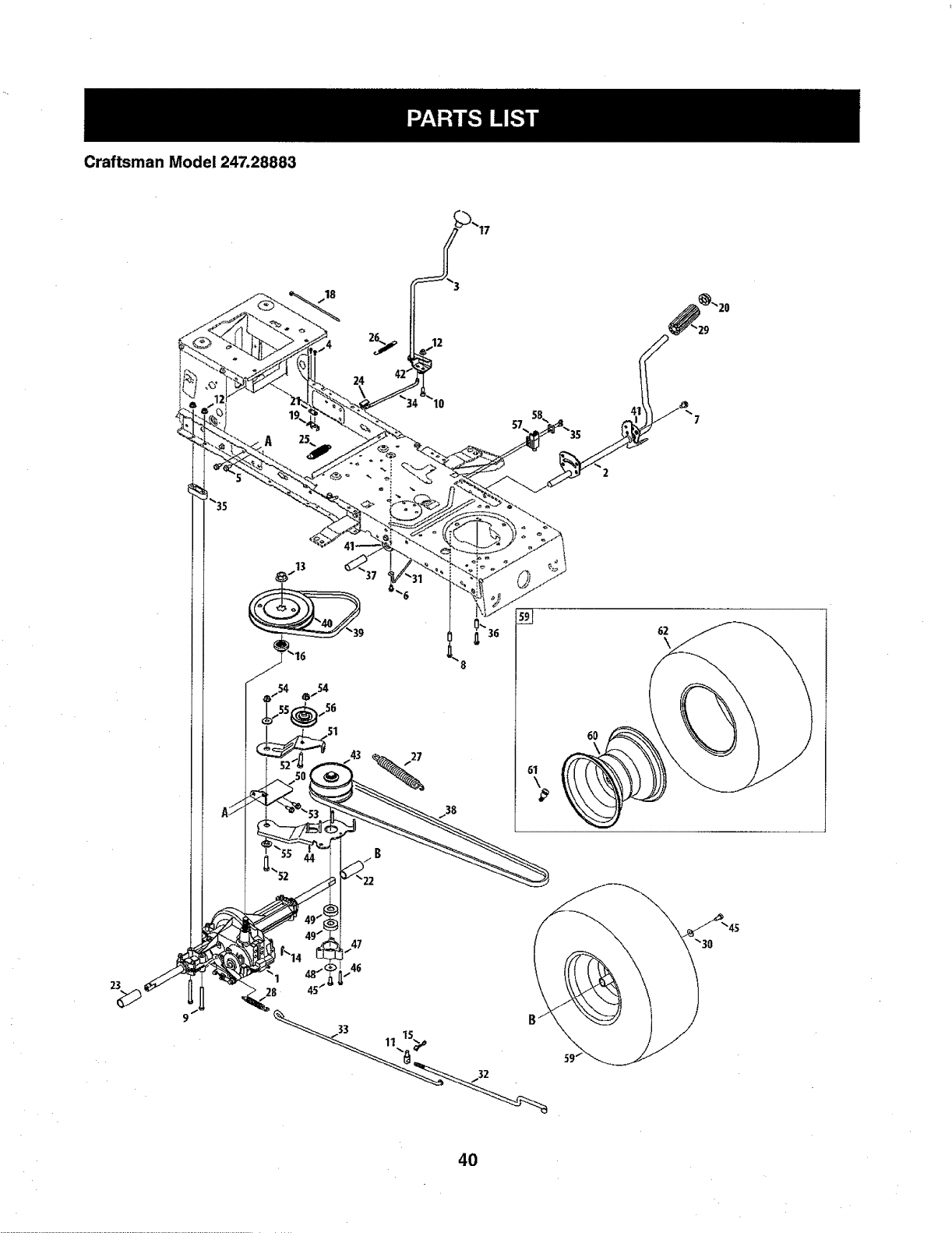
Craftsman Model 247.28883
24
10
38
62
6O
23
40

Craftsman Model 247.28883
I
2
3
4
5
6
7
8
9
lO
11
12
13
14
15
16
17
I8
19
20
21
22
23
24
:=25
26
27
28
29
30
31
32
918-04566
647-04034C-0637
647-04035
710-0227
710-04484
7!0-0599
7t0-0604A
710-0809
710-0176
710-3008
911-04075A
712-04063
712-0700
914-0209
7t4-04040
718-04407
720-04028
725-0t57
725-1644
726-0214
926-0320
731-04602
731-04604
731-O6894
732-04306
732-04488
732-04746
732-0716D
735-0239
736-0242
747-04969
747-95186
Description
TransmissionDriveAssembly
PedalAssembly
ShaftLeverAssembly
Screw,8-18:0.500
Screw,5/16-18x °750
Screw,1/4-20x0.500
Screw,5/16-18x 0.625
Screw,1/4-20x 1.250
HexScrew,5/I6-t8 x 2,75
HexScrew,5/16-18x .75
Ferrule,3/8-24X .375DIA.
FlangelockNut,5/16-18
FlangeNut,9116-18
CotterPin]NT-.t25 DIA
Bow-T_eCotterPin
PulleyHub,5/8SPLINE
ShiftKnob
CableTie
iShortSpringSwitch
PushCap,5/8
PlateInsulatorNut
Sleeve,.758x .821x 3.3125
Sleeve,.758x .821x 2.4375
ShiftBearingPlate
SpringExtension,.89ODx3.28LG
SpringExtension,.38ODx 3.25LG
SpringExtension,.94ODx 6.75LG
SpringExtension,.59ODx4.00LG
FootPad,4.9LONG
BellWasher,.340x.872x.060
BeltKeeperRod
VariableSpeedControlRod
Ref.
NO.
33
34
35
36
37
38
139
40
41
42
43
44
45
46
47
48
49
5O
51
52
53
54
55
56
57
58
59
60
61
62
Part No.
747-05188
747_05244
738-04237A
759-0566A
750-0802
954-04249
954-0241A
956-04002
783-04536B-0637
783-04595A
956-04015A
683-04206
7t0-0627
710-0778
718-04261
736-0362
941-0600
683-04!76A
683-04207
719-0347
710-1260A
712-04065
938-0347
756-04325
725-04363
17962
634-0t04
634-043694042
934-0255
734-1730
925-04082
Description
::, ,,,,,,,,,,,_......... _
BrakeRod
ShiftRod
[ShoulderScrew,#10-32x.500
Spacer,.269x.375x1.030LG
Spacer,.640tDx .76ODx 2.63
V Belt,5L:70.90POLY
V Belt,5L:35.25POLY
Trans,Pulley
PedalSupportBracket
ShaftAdjustBracket
VariableSpeedPulleyAssembly
BracketAssembly
HexScrew,5/16-24x .750
Screw,1/4-20x 1.500
BearingCup
FlatWasher,.330x 1.25x .06:HT
BallBearing,17x40 x 12
TransmissionBracketAssembly
IdlerBracketAssembly
HexScrew,3/8-16x 1.75
Screw,5/16-18x9.750
FlangeLockNut,3/8-16
ShoulderSpacer,.625IDx .169
IdlerPulley
SwitchInterlock
PlateSwitch
WheelAssembly,20 x8 x 8 Sq.Sh.
RimAssembly
ValveStem
Tire,20x 8 x8 Sq.Sh.
WiringHarness(NotShown)
41
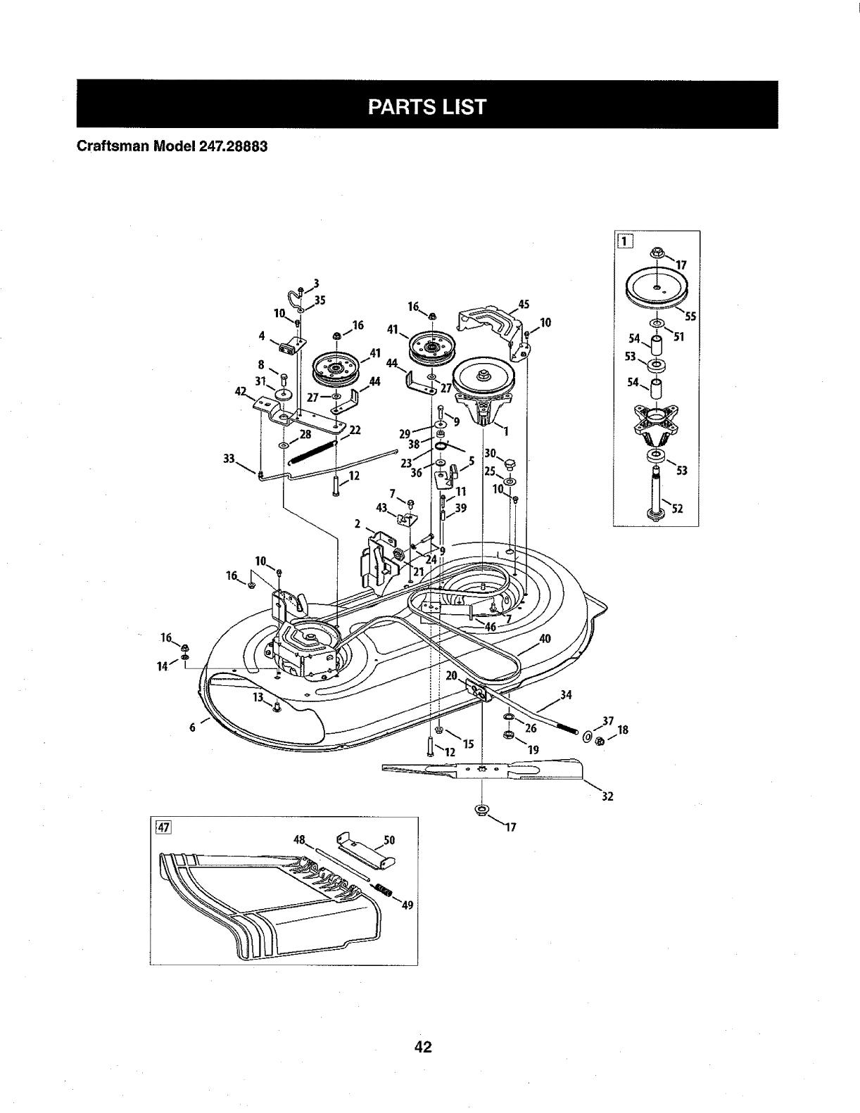
Craftsman Model 247.28883
12
45
54_51
53\_
54_
34
37
(_/18
32
42
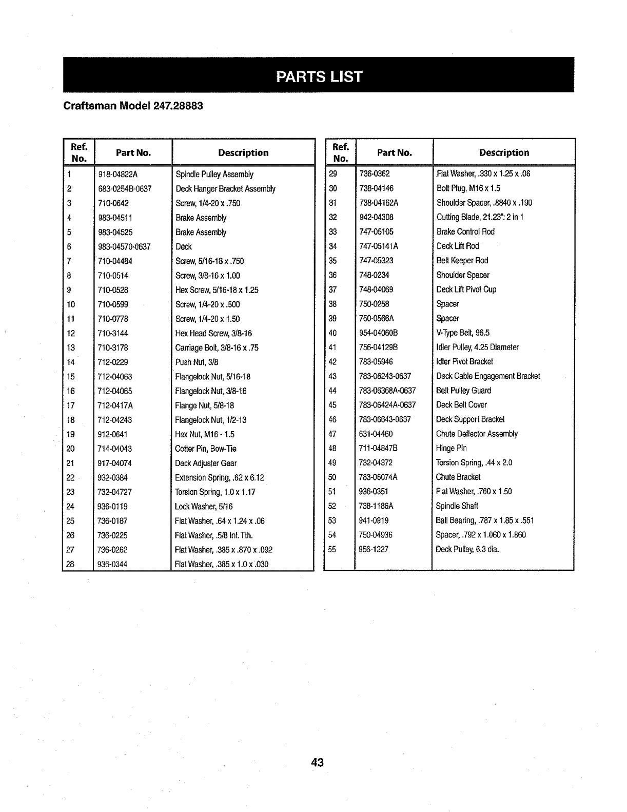
Craftsman Model 247.28883
"°'l
NO.
t
2
3
4
5
6
7
8
9
lO
11
12
13
14
15
16
17
18
19
2o
21
22
23
24
25
26
27
28
Part No. Description
918-04822A
683-0254B-0637
710-0642
983-045tl
983-04525
983-04570-0637
SpindlePulleyAssembly
DeckHangerBracketAssembly
Screw,114-20x.750
BrakeAssembly
BrakeAssembly
Deck
710-04484
710-0514
710.0528
710.0599
710-0778
710-3144
7t0-3178
712-0229
712-04063
712-04065
712-0417A
712-04243
912-0641
714-04043
917-04074
932-0384
732-04727
936-0119
736-0187
736-0225
736-0262
936-0344
Screw,5116-18x .750
Screw,3/8-16x 1,00
HexScrew,5/16.18x 1.25
Screw,1t4-20x.500
Screw,114-20x 1.50
HexHeadScrew,3/8-16
CarriageBolt,3/8-16x .75
PushNul,3!8
FlangelockNut,5/16-18
FlangelockNut,318-I6
FlangeNut,5f8-18
FlangelockNut,112-13
HsxNut,M16- 1.5
CotterPin,Bow-Tie
DeckAdjusterGear
ExtensionSpring,.62x6.12
TorsionSpring,1.0x 1.17
LockWasher,5/t6
FlatWasher,.64x 1.24x .06
FlatWasher,.5!8Int.Tth.
FlatWasher,.385x .870x .092
FlatWasher,.385x 1.0x.030
!Part No.No.
i
29 736-0362
30 738-O4146
31 738-04162A
32 942-04308
33 747-05105
34 747-0514tA
35 747-05323
36 748-0234
37 748-04O69
38 750-0258
39 750-0566A
40 964-04060B
141 756-04129B
i42 783-05946
43 783-06243-0637
44 783-06368A-0637
45 783-06424A-0637
46 783-06643-0637
47 63t-04460
48 711-04847B
49 732-04372
50 783-06074A
51 936-0351
52 738-t186A
53 941-0919
54 750-04936
55 956-1227
Description
Fiat Washer,.330x 1.25x .06
Bo]tPlug,Mt6 x 1.5
ShoulderSpacer,.8840x.190
CuttingBlade,21.23":2 in 1
BrakeConlrolRod
DeckLiftRod
BeltKeeperRod
ShoulderSpacer
DeckLift PivotCup
Spacer
Spacer
V-TypeBelt,96.5
IdlerPulley,4.25Diameter
IdlerPivotBracket
DeckCableEngagementBracket
BeltPulleyGuard
DeckBeltCover
DeckSupportBracket
ChuteDeflectorAssembly
HingePin
TorsionSpring,.44x2.0
ChuteBracket
FlatWasher,.760x 1.50
SpindleShaft
BallBearing,.787x 1.85x .551
Spacer,.792x1.060x 1.860
DeckPulley,6.3dia.
43
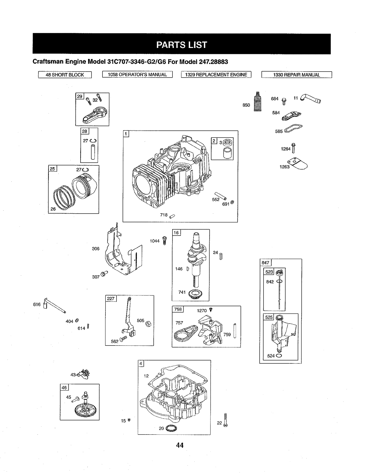
Craftsman Engine Model 31C707-3346-G2/G6 For Model 247,28883
[ 48 SHORT BLOCK ] I1058 OPERATOR'S MANUAL I{ 1329 REPLACEMENT ENGINE ! [ 1330 REPAfR MANUAL
85O
584
25I 270
718
404 @
8_4It
1044
5o5_
146 !
741
691 @
24_]
1270
158
4j
2,,0 22_
!52.'
524 0
44
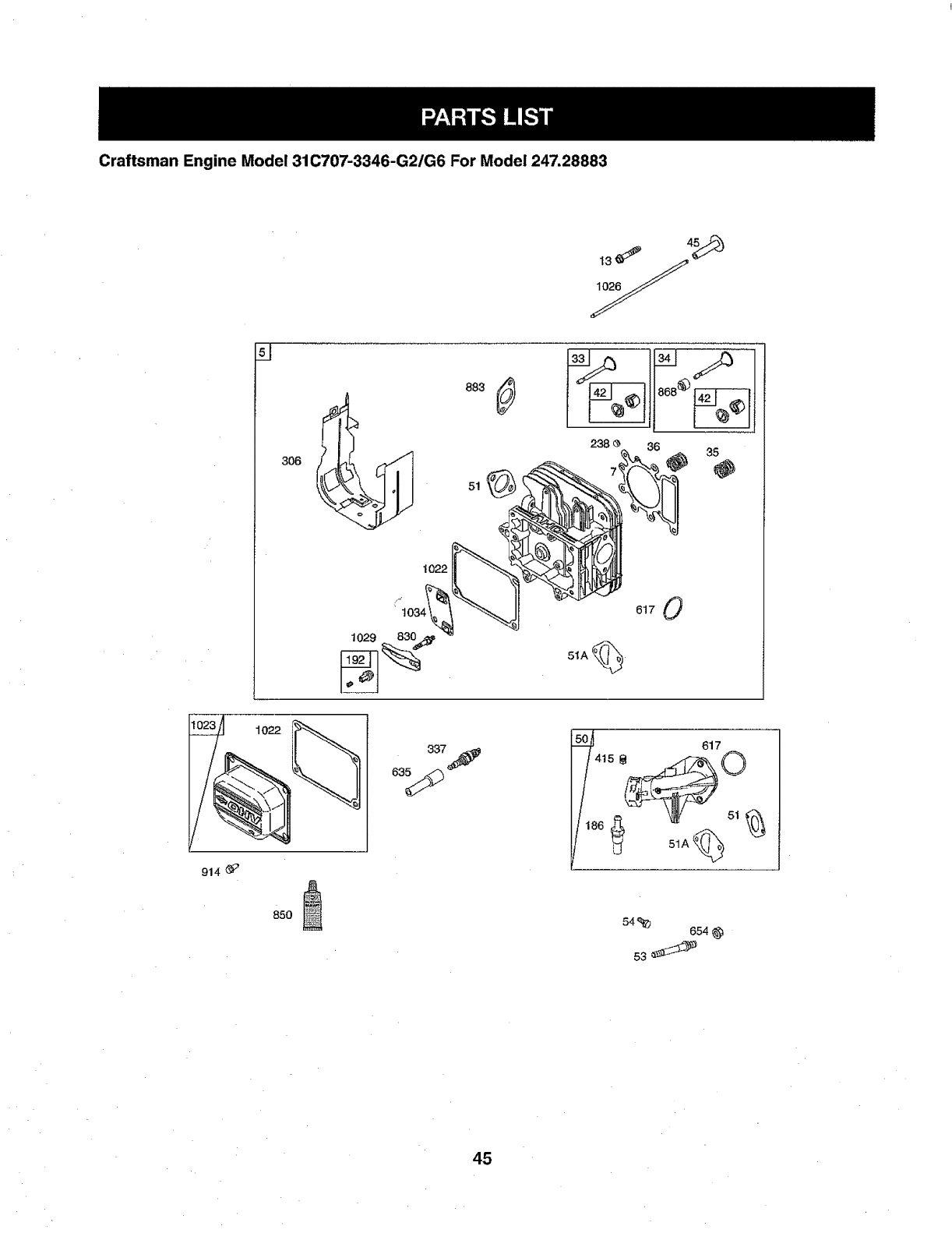
Craftsman Engine Model 31C707-3346-G2/G6 For Model 247,28883
238 <_ 36 35
@
51A
617 0
914 _;'
1022
337_
63_
617
186 _ _ir 51_i_
51A_
85O 54'e_b 654
45
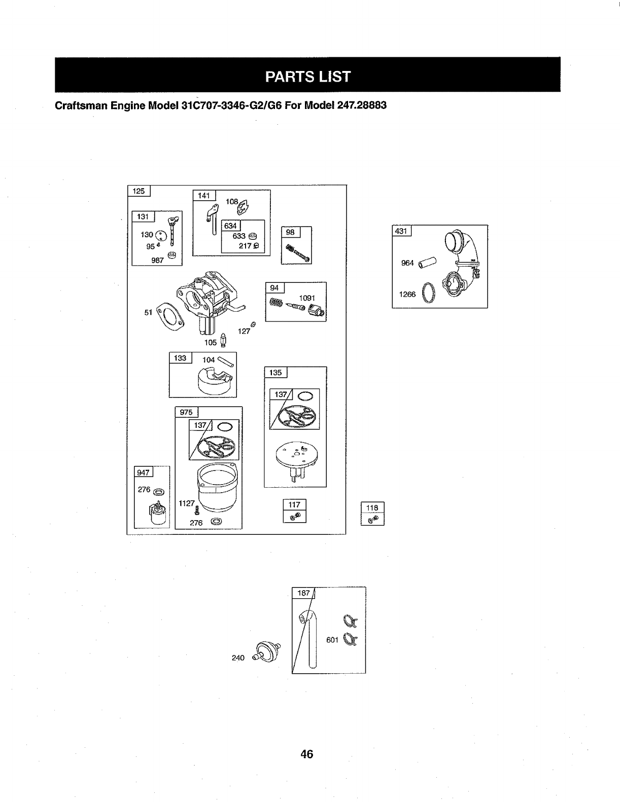
CraftsmanEngineModel31C707-3346-G2/G6For Model247.28883
,3o©HI _
I633 Q
95,_ u I217 ,._
987 _'
105
276 @
_ 112;76 @
964
1266 0
601
46
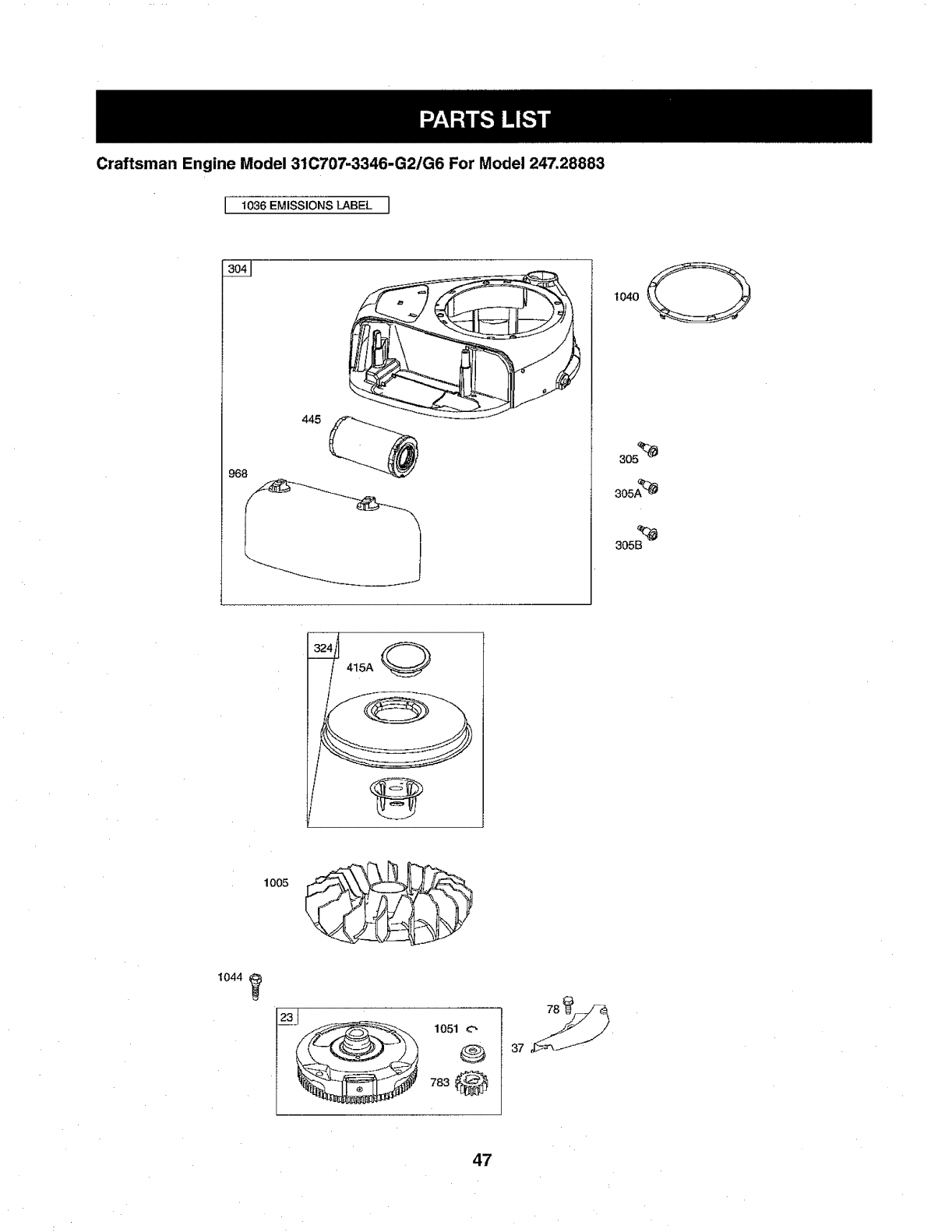
Craftsman Engine Model 31C707-3346-G2/G6 For Model 247.28883
I1036 EMISSIONS LABEL I
968
3o_
305A_
1005
1044
I_ 1051 o
®
783 O
47

Craftsman Engine Model 31C707-3346-G2/G6 For Model 247.28883
1051 _
?'83
513 _
462
579
801
697
1119
1054
216 232 209
222
267
48
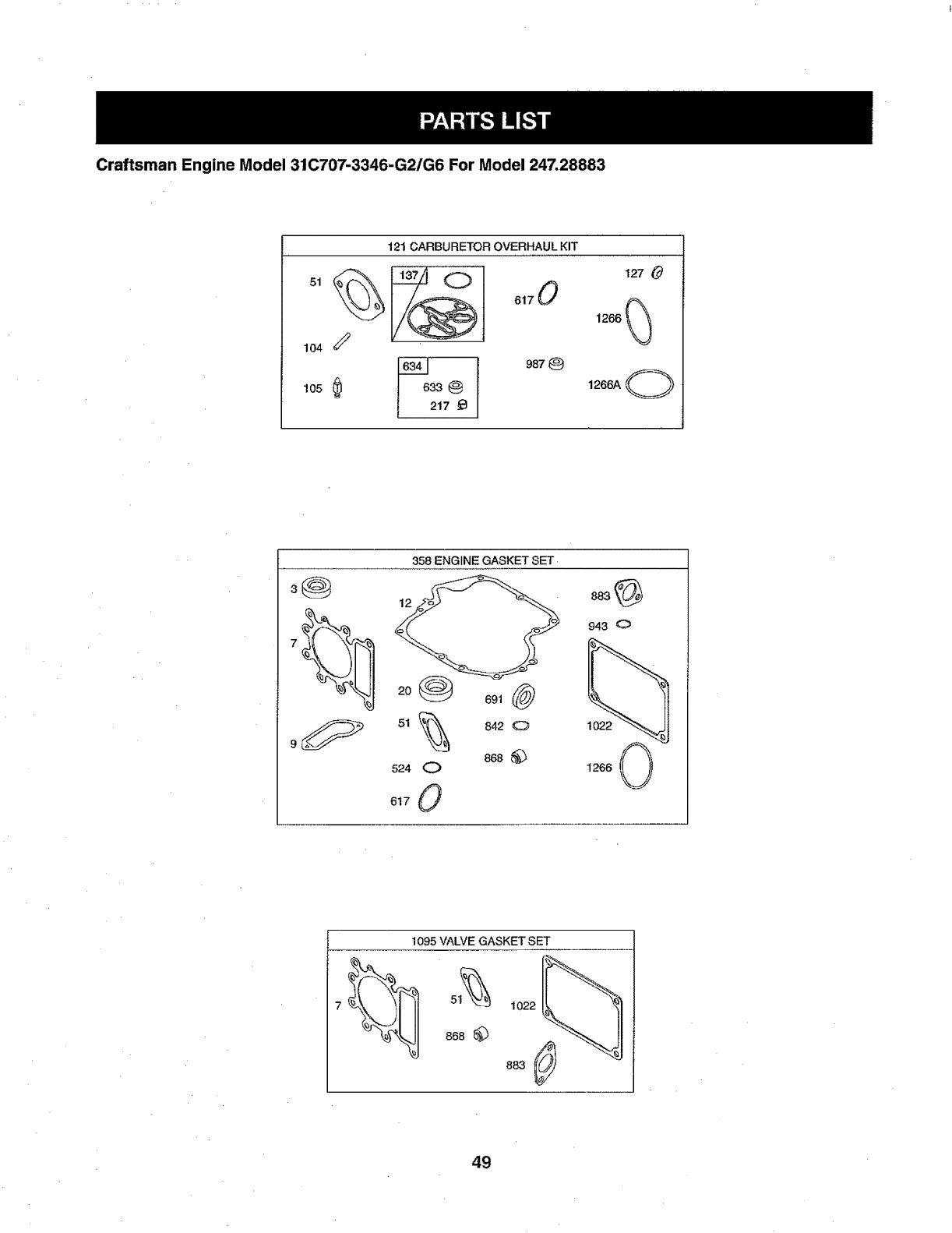
Craftsman Engine Model 31C707-3346-G2/G6 For Model 247.28883
121 CARBURETOR OVERHAUL KIT
lo4
|2_7 e
127 O
1266_
1266A O
358 ENGINE GASKET SET
3@ 12
524 0
617 0
668
1022
1266 0
1095 VALVE GASKET SET
1022
883
49
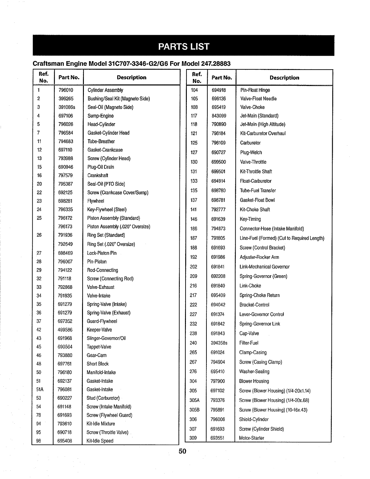
Craftsman Engine Model 31C707-3346-G2/G6 For Model 247.28883
RefiNo.J PartNo,
1796010
2 399265
3 391086s
4 697106
5 796026
7 796584
11 794683
12 697110
13 793988
t5 690946
16 797579
20 795387
22 692125
23 698281
24 796335
25 796172
796173
791936
792649
698469
796007
794122
791118
792868
791935
691279
691279
697352
499586
691968
690564
793880
697761
796180
692137
796081
690227
691148
691693
793610
690718
695408
26
27
28
29
32
33
34
35
36
37
42
43
45
46
48
80
51
51A
53
54
78
94
95
98
Description
CylinderAssembly
BushinglSealKit (MagnetoSide)
Seal-Oil(MagnetoSide)
Sump-Engine
Head-Cylinder
Gasket-CylinderHead
Tube-Breather
Gasket-Crankcase
Screw(CylinderHead)
Plug-OilDrain
Crankshaft
Seal-Oi!(PTOSide)
Screw(CrankcaseCovedSump)
Flywheel
Key-Flywheel(Steel)
PistonAssembly(Standard)
PistonAssembly(.020° Oversize)
RingSet(Standard)
RingSet(.020"Oversize)
Lock-PistonPin
Pin-Piston
Rod-Connecting
Screw(ConnectingRod)
Valve-Exhaust
Valve-Intake
Spring-Valve(Intake)
Spring-Valve(Exhaust)
Guard-Flywheel
Keeper-Valve
Slinger-Governor!Oil
Tappet-Valve
Gear-Cam
ShortBlock
Manifold-Intake
GaskeNntake
Gasket-Intake
Stud(Carburetor)
Screw(IntakeManifold)
Screw(FlywheelGuard)
Kit-IdleMixture
Screw(ThrottleValve)
Kit-IdleSpeed
5O
"°"lNo. PartNo.
104 694918
105 696136
108 695419
117 843099
I18 790890
t21 796184
125 796109
127 690727
130 699500
I31 699501
133 694914
135 698780
137 698781
141 792777
!46 691639
t86 794873
187 791805
188 691693
192 691986
202 691841
209 692208
216 691840
217 695409
222 694042
227 691374
232 691842
238 891843
240 394358s
265 691024
267 794904
276 695410
304 797900
305 697102
305A 793376
305B 795891
306 796006
307 691693
309 693551
Description
Pin-FloatHinge
Valve-FloatNeedle
Valve-Choke
Jet-Main(Standard)
Jet-Main(HighAltitude)
Kit-CarburetorOverhaul
Carburetor
Plug-Welch
Valve-Throttle
Kit-ThrottleShaft
Float-Carburetor
Tube-FuelTransfer
Gasket-FloatBowl
Kit-ChokeShaft
Key-Timing
Connector-Hose(IntakeManifold)
Line-Fuel(Formed)(Cutto RequiredLength)
Screw(ControlBracket)
Adjuster-RockerArm
Link-MechanicalGovernor
Spring-Governor(Green)
Link-Choke
Spring-ChokeReturn
Bracket-Control
Lever-GovernorControl
Spring-GovernorLink
Cap-Valve
Filter-Fuel
Clamp-Casing
Screw(CasingClamp)
Washer-Sealing
BlowerHousing
Screw(BlowerHousing)(1/4-20x1.14)
Screw(BlowerHousing)(1t4-20x,68)
Screw(BlowerHousing)(10-t6x.43)
Shield-Cylinder
Screw(CylinderShield)
Motor-Starter
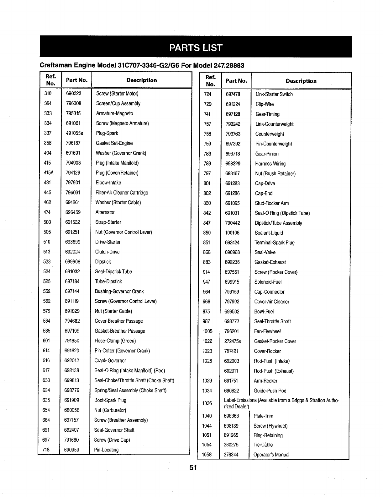
Craftsman Engine Model 31C707-3346-G2/G6 For Model 247.28883
ReL I
NP_ I Part No.
,,,,, ,,, ,,, ,r,
310 690323
324 796308
333 795315
334 691061
337 491055s
358 796187
404 691691
415 794903
415A 794129
43I 797901
445 796031
462 691261
474 696459
503 691532
505 691251
510 693699
5!3 692024
523 699908
524 691032
525 697184
552 697144
562 691119
579 691029
584 794682
585 697109
601 791850
614 691620
616 692012
6_7 692138
633 699813
634 698779
635 691909
654 690958
684 697157
691 692407
697 791680
718 690959
Description
Screw(StarterMotor)
Screen/CupAssernbly
Armature+Magneto
Screw(MagnetoArmature)
Ptug-Spark
GasketSet-Engine
Washer(GovernorCrank)
Plug(IntakeManifold)
Plug(CovertRetainer)
Elbow-Intake
Filter-AirCleanerCartridge
Washer(StarterCable)
Alternator
Strap-Starter
Nut(GovernorControlLever)
Drive-Starter
Clutch-Drive
Dipstick
Seat-DipstickTube
Tube-Dipstick
Bushing-GovernorCrank
Screw(GovernorControlLever)
Nut(StarterCable)
Cover-BreatherPassage
Gasket-BreatherPassage
Hose-Clamp(Green)
Pin-Cotter(GovernorCrank)
Crank-Governor
Seaf-ORing(IntakeManifold)(Red)
Seal-Choke/ThrottleShaft(ChokeShaft)
Spring/SealAssembly(ChokeShaft)
Boot-SparkPlug
Nut(Carburetor)
Screw(BreatherAssembly)
Seal-GovernorShaft
Screw(DriveCap)
Pin-Locating
I Part No.No.
M
724 697478
729 691224
741 697128
757 793242
758 793763
759 697392
783 693713
789 698329
797 693167
801 691283
802 691286
830 691095
842 691031
847 790442
850 100106
851 692424
868 690968
883 692236
914 697551
947 699915
964 799159
968 797902
975 699502
987 698777
I005 796201
1022 272475s
1023 797421
1026 692003
692011
691751
690822
1029
1034
1036
1040
1044
1051
1054
t058
51
Description
Label-Emissions (Available from a Briggs & Stratton Autho-
rized Dealer)
698368
698139
691265
280275
276344
Plate-Trim
Screw(Flywheel)
Ring-Retaining
Tie-Cable
Operator'sManual
,,, i,
Link-StarterSwitch
Clip-Wire
Gear-Timing
Link-Counterweight
Counterweight
Pin-Counterweight
Gear-Pinion
Harness-Wiring
Nut(BrushRetainer)
Cap-Drive
Cap-End
Stud-RockerArm
SeaI-ORing(DipstickTube)
Dipstick/TubeAssembly
Sealant-Liquid
Terminal-SparkPlug
Seal-Valve
Gasket-Exhaust
Screw(RockerCover)
Solenoid-Fuel
Cap-Connector
Cover-AirCleaner
Bowl-Fuel
Seal-ThrottleShaft
Fan-Flywheel
Gasket-RockerCover
Cover-Rocker
Rod-Push(Intake)
Rod-Push(Exhaust)
Arm-Rocker
Guide-PushRod
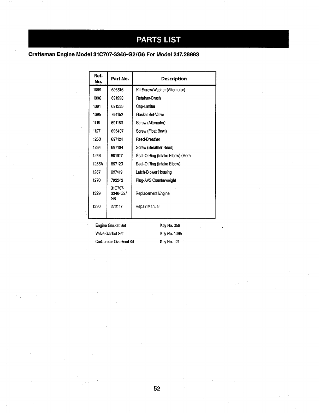
Craftsman Engine Model 310707-3346-G2/G6 For Model 247.28883
Ref. I
No.
1059
1090
1091
1095
1119
1127
1263
t264
1266
1266A
1267
t270
1329
1330
Part No.
698516
691293
691333
794152
691183
695407
697124
697104
691917
697123
697419
793243
31C707-
3346-G21
G6
272147
Description
Kit-ScrewN/asher (Alternator)
RetainePBrush
Cap-Limiter
GasketSetNalve
Screw(Alternator)
Screw(FloatBowl)
Reed-Breather
Screw(BreatherReed)
SeaI-ORing(intakeElbow)(Red)
Seal-ORing(IntakeElbow)
Latch-BlowerHousing
Plug-AVSCounterweight
ReplacementEngine
RepairManual
EngineGasketSet
ValveGasketSet
CarburetorOverhaulKit
Key No. 358
Key No. t095
Key No. 121
52
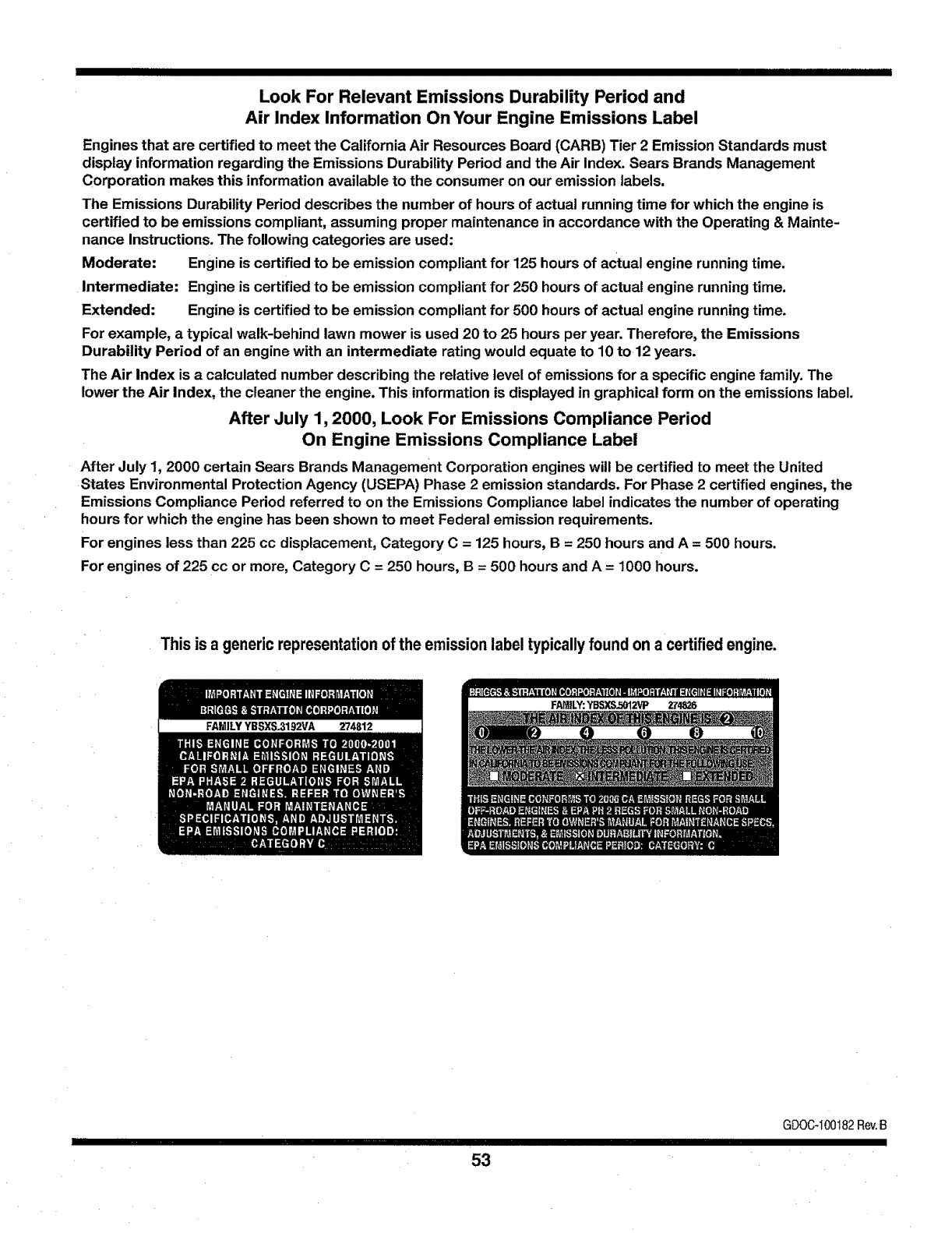
IIIIIII IIII III IIIIIIIIIIII
Look For Relevant Emissions Durability Period and
Air Index Information On Your Engine Emissions Label
Engines that are certified to meet the California Air Resources Board (CARB) Tier 2 Emission Standards must
display information regarding the Emissions Durability Period and the Air Index. Sears Brands Management
Corporation makes this information available to the consumer on our emission labels.
The Emissions Durability Period describes the number of hours of actual running time for which the engine is
certified to be emissions compliant, assuming proper maintenance in accordance with the Operating & Mainte-
nance instructions. The following categories are used:
Moderate: Engine is certified to be emission compliant for 125 hoursof actual engine running time.
Intermediate: Engine is certified to be emission compliant for 250 hours of actual engine running time.
Extended: Engine is certified to be emission compliant for 500 hours of actual engine running time.
For example, a typical walk-behind lawn mower is used 20 to 25 hours per year. Therefore, the Emissions
Durability Period of an engine with an intermediate rating would equate to 10 to12 years.
The Air Index is acalculated number describing the relative level of emissions for a specific engine family. The
lower the Air Index, the cleaner the engine. This information is displayed in graphical form on the emissions label.
After July 1, 2000, Look For Emissions Compliance Period
On Engine Emissions Compliance Label
After July 1, 2000 certain Sears Brands Management Corporation engines will be certified to meet the United
States Environmental Protection Agency (USEPA) Phase 2 emission standards. For Phase 2 certified engines, the
Emissions Compliance Period referred to on the Emissions Compliance label indicates the number of operating
hours for which the engine has been shown to meet Federal emission requirements.
For engines less than 225 cc displacement, Category C = 125 hours, B = 250 hours and A = 500 hours.
For engines of 225 cc or more, Category C = 250 hours, B = 500 hours and A= 1000 hours.
This is agenericrepresentationofthe emissionlabeltypicallyfound ona certifiedengine.
FAMILY YBSXS.3192VA 274812
IIIIHI IIII I
53
GDOC-100182Rev.B
(Thispageapplicableinthe U.S.A,andCanadaonly.)
Sears Brands Management Corporation (Sears), the California Air Resources Board (CARB)
and the United States Environmental Protection Agency (U.S. EPA)
Emission Control System Warrant-j Statement (Owner's Defect Warranty Rights and Obligations)
EMISSIONCONTROLWARRANTYCOVERAGEISAPPLICABLETOCERTI-
FIEDENGINESPURCHASEDINCALIFORNIAIN1995ANDTHEREAF-
TER,WHICHAREUSEDINCALIFORNIA,ANDTOCERTIFIEDMODEL
California and United States Emission
TheCaliforniaAirResourcesBoard(CARB),U.S.EPAandSearsarepleased
to explainthe EmissionControlSystemWarrantyonyourmodelyear2000and
latersmalloff-roadengine(SORE).InCalifornia,newsmalloff-roadengines
mustbe designed,builtandequippedto meettheState'sstringentanti-smog
standards.Elsewherein theUnitedStates,newnon-road,spark-ignition
enginescertifiedformodelyear1997andlatermustmeetsimilarstandardsset
forthbytheU.S.EPA.Searsmustwarranttheemissioncontrolsystemonyour
YEAR1997ANDLATERENGINESWHICHAREPURCHASEDANDUSED
ELSEWHEREINTHEUNITEDSTATES(ANDAFTERJANUARY1,2001IN
CANADA).
Control Defects Warranty Statement
enginefortheperiodsof timelistedbelow,providedtherehasbeennoabuse,
neglectorimpropermaintenanceofyoursmalloff-roadengine.Youremis-
sioncontrolsystemincludespartssuchasthecarburetor,air cleaner,ignition
system,mufflerandcatalyticconverter.Alsoincludedmaybeconnectorsand
otheremissionrelatedassemblies.Whereawarrantableconditionexists,Sears
willrepairyoursmalloff-roadengineat nocostto youincludingdiagnosis,parts
andlabor.
Sears Emission Control Defects Warranty Coverage
Smalloff-roadenginesarewarrantedrelativetoemissioncontrolpartsdefects
fora periodof oneyear,subjectto provisionssetforthbelow,Ifanycovered
Owner's Warranty
Asthesma!loff-roadengineowner,youareresponsiblefortheperformanceof
therequiredmaintenancelistedinyourOperatingandMaintenanceInstruc-
tions.Searsrecommendsthatyouretainallyourreceiptscoveringmaintenance
onyoursmalloff-roadengine,butSearscannotdenywarrantysolelyforthe
lackof receiptsor foryourfailureto ensuretheperformanceof all scheduled
maintenance.As thesmalloff-roadengineowner,youshouldhoweverbe
awarethatSearsmaydenyyouwarrantycoverageifyoursmalloff-roadengine
ora parthasfaileddueto abuse,neglect,impropermaintenanceor unap-
partonyourengineisdefective,thepartwillberepairedorreplacedbySears,
Responsibilities
provedmodifications.Youareresponsibleforpresentingyoursmalloff-road
enginetoanAuthorizedSearsServiceDealeras soonasaproblemexists.The
undisputedwarrantyrepairsshouldbecompletedinareasonableamountof
time,nottoexceed30days.Ifyouhaveanyquestionsregardingyourwarranty
rightsandresponsibilities,youshouldcontacta SearsServiceRepresentative
at 1-800-469-4663.Theemissionwarrantyisa defectswarranty.Defectsare
judgedonnormalengineperformance.Thewarrantyisnotrelatedto anin-use
emissiontest.
Sears Emission Control Defects Warranty Provisions
ThefollowingarespecificprovisionsrelativetoyourEmissionControlDefectsWarrantyCoverage.ttisinadditiontotheSearsenginewarrantyfornon-regulated
enginesfoundintheOperatingandMaintenanceInstructions.
1. WarrantedParts
Coverageunderthiswarrantyextendsonlyto thepartstistedbelow(the
emissioncontrolsystemsparts)totheextentthesepartswerepresenton
theenginepurchased.
a. FuelMeteringSystem
•Coldstartenrichmentsystem
•Carburetorandinternalparts
•FuelPump
b. AirInductionSystem
•Air cleaner
•Intakemanifold
c. IgnitionSystem
•Sparkplug(s)
, Magnetoignitionsystem
d. CatalystSystem
•Catalyticconverter
, Exhaustmanifold
•Air injectionsystemorpulsevalve
e. MiscellaneousItemsUsedinAboveSystems
•Vacuum,temperature,position,timesensitivevalves
andswitches
• Connectorsandassemblies
2. LengthofCoverage
Searswarrantstotheinitialownerandeachsubsequentpurchaserthat
theWarrantedPartsshallbefreefromdefectsin materialsandworkman-
shipwhichcausedthefailureof theWarrantedPartsfora periodofone
yearfromthedatetheengineisdeliveredtoa retailpurchaser.
3. NoCharge
RepairorreplacementofanyWarrantedPartwillbe performedat no
chargeto theowner,includingdiagnosticlaborwhichleadsto the
determinationthata WarrantedPartisdefective,ifthediagnosticworkis
performedat anAuthorizedSearsServiceDealer.Foremissionswarranty
servicecontactyournearestAuthorizedSearsServiceDealeraslistedin
the"YellowPages"under"Engines,Gasoline,""GasolineEngines,""Lawn
Mowers,"orsimilarcategory.
4. ClaimsandCoverageExclusions
Warrantyclaimsshallbefiledinaccordancewiththeprovisionsof the
SearsEngineWarrantyPolicy.Warrantycoverageshallbeexcludedfor
failuresof WarrantedPartswhicharenotoriginalSearspartsorbecause
of abuse,neglector impropermaintenanceassetforthintheSears
EngineWarrantyPolicy.Searsis notliableto coverfailuresof Warranted
Partscausedbytheuseofadd-on,non-original,or modifiedparts.
5. Maintenance
AnyWarrantedPartwhichisnotscheduledforreplacementasrequired
maintenanceorwhichisscheduledonlyfor regularinspectionto theeffect
of "repairorreplaceasnecessary"shallbewarrantedastodefectsforthe
warrantyperiod.AnyWarrantedPartwhichis scheduledforreplacement
asrequiredmaintenanceshahbewarrantedas todefectsonlyforthe
periodoftimeup tothefirstscheduledreplacementforthatpart.Any
replacementpartthatis equivalentinperformanceanddurabilitymay
beusedintheperformanceofany maintenanceor repairs.Theowneris
responsiblefortheperformanceof all requiredmaintenance,asdefinedin
theSearsOperatingandMaintenanceInstructions.
6. ConsequentialCoverage
Coveragehereundershallextendto thefailureof anyenginecomponents
causedbythefailureofanyWarrantedPartstill underwarranty.
IntheUSAandCanada,a 24hourhotline,1-800-469-4663,hasa menuof pre-recordedmessagesofferingyouenginemaintenanceinformation.
GDOC-100188 Roy.B
54
IIIIIIIIII IIIII IIIIIIIIIII
FEDERAL and/or CALIFORNIA EMISSION CONTROL WARRANTY STATEMENT
YOUR WARRANTY RIGHTS AND OBLIGATIONS
MTDConsumerGroupInc,theUnitedStatesEnvironmentalProtectionAgency(EPA),and,forthoseproductscertifiedforsaleinthestateofCalifornia,the
CaliforniaAirResourcesBoard(GARB)arepleasedtoexplaintheemission(evaporativeandlorexhaust)controlsystem(ECS)warrantyonyouroutdoor2006
andlatersmalloff-roadspark-ignitedengineandequipment(outdoorequipmentengine)InCalifornia,newoutdoorequipmentenginesmustbedesigned,bui{tand
equippedtomeettheState'sstringentanti-smogstandards(inotherstates,1997andlatermodelyearequipmentmustbedesigned,built,andequippedto meet
theU.S.EPAsmalloff-road,sparkignitionengineregulations.MTDConsumerGrouptnc mustwarranttheECSonyouroutdoorequipmentenginefortheperiodof
timelistedbelowprovidedtherehasbeennoabuse,neglectorimpropermaintenanceofoutdoorequipmentengine.
YourECSmayincludepartssuchas thecarburetor,fuel-injectionsystem,theignitionsystem,catalyticconverter,fueltanks,fuellines,fuelcaps,valves,canisters,
filters,vaporhoses,clamps,connectors,andotherassociatedemission-relatedcomponents.
Whereawarrantableconditionexists,MTDConsumerGroupIncwillrepairyouroutdoorequipmentengineat nocosttoyouincludingdiagnosis,partsandlabor.
MANUFACTURER'S WARRANTY COVERAGE:
Thisemissioncontrolsystemiswarrantedfortwoyears.Ifanyemission-relatedpartonyouroutdoorequipmentengineisdefective,thepartwillberepairedor
replacedbyMTDCONSUMERGROUPiNC.
OWNER'S WARRANTY RESPONSIBILITIES:
Astheoutdoorequipmentengineowner,youareresponsiblefor performanceoftherequiredmaintenancelistedinyourowner'smanual.MTDConsumerGroup
Increcommendsthatyouretainallreceiptscoveringmaintenanceonyouroutdoorequipmentengine,butMTDConsumerGroupInccannotdenywarrantysolely
forthelackof receipts.
Astheoutdoorequipmentengineowner,youshouldhoweverbeawarethatMTDConsumerGroupIncmaydenyyouwarrantycoverageifyouroutdoorequipment
engineora parthasfaileddueto abuse,neglect,orimpropermaintenanceor unapprovedmodifications.
Youareresponsiblefor presentingyouroutdoorequipmentenginetoMTDConsumerGrouplnc'sdistributioncenterorservicecenterassoonastheproblem
exists.Thewarrantyrepairsshouldbecompletedina reasonableamountof time,nottoexceed30 days.Jfyouhavea questionregardingyourwarrantycoverage,
youshouldcontacttheMTDConsumerGroupIncServiceDepartmentat !-800-800-7310orviaemailat http:/fsupport.mtdproducts.com
GENERAL EMISSIONS WARRANTY COVERAGE:
MTDConsumerGrouplncwarrantsto theultimatepurchaserandeachsubsequentpurchaserthattheoutdoorequipmentengineis:Designed,builtandequipped
soastoconformwithaFIapplicableregulations;andfreefromdefectsinmaterialsandworkmanshipthatcausethefailureof awarrantedparttobeidenticalinall
materiairespectstothatpartasdescribedinMTDConsumerGroupInc'sapplicationforcertification.
Thewarrantyperiodbeginson thedatetheoutdoorequipmentengineis deliveredto an ultimatepurchaserorfirstplacedintoservice.Thewarrantyperiodistwo
years.
Subjecttocerta{nconditionsandexclusionsasstatedbelow,thewarrantyon emission-relatedpartsis asfollows:
1. Anywarrantedpartthatisnotscheduledforreplacementas requiredmaintenanceinthewritteninstructionssupplied,is warrantedfor thewarrantyperiod
statedabove.If thepartfailsduringtheperiodofwarrantycoverage,thepartwiltbe repairedorreplacedbyMTDConsumerGroupIncaccordingtosubsection
(4)below.Anysuchpartrepairedorreplacedunderwarrantywillbewarrantedfortheremainderoftheperiod.
2. Anywarrantedpartthatisscheduledonlyforregularinspectioninthewritteninstructionssuppliedis warrantedforthewarrantyperiodstatedabove.Anysuch
partrepairedorreplacedunderwarrantywillbewarrantedfortherema{ningwarrantyperiod.
3. Anywarrantedpartthatis scheduledforreplacementasrequiredmaintenanceinthewritteninstructionssuppliediswarrantedforthe periodof timebeforethe
firstscheduledreplacementdateforthatpart.Ifthepartfailsbeforethefirstscheduledreplacement,thepartwillberepairedorreplacedby MTDConsumer
GroupIncaccordingto subsection(4) below.Anysuchpartrepairedorreplacedunderwan'antywil!be warrantedfortheremainderoftheperiodpriortothe
firstscheduledreplacementpointforthepart.
4. Repairorreplacementof anywarrantedpart underthewarrantyprovisionshereinmustbe performedata warrantystationat no chargeto theowner.
5. Notwithstandingtheprovisionsherein,warrantyservicesorrepairswillbe providedatallof ourdistributioncentersthatarefranchisedto servicethesubject
enginesorequipment.
6. Theoutdoorequipmentengineownerwillnotbechargedfordiagnosticlaborthatis directlyassociatedwithdiagnosisofa defective,emission-relatedwar-
rantedpart,providedthatsuchdiagnosticworkisperformedata warrantystation.
7. MTDConsumerGroupIncisliablefor damagesto otherengineorequipmentcomponentsproximatelycausedbya failureunderwarrantyof anywarranted
part.
8. Throughouttheoff-roadengineandequipmentwarrantyperiodstatedabove,MTDConsumerGroupIncwi]lmaintainasuppEyofwar[antedpartssufficientto
meettheexpecteddemandforsuchparts.
9. Anyreplacementpartmaybeusedinthe performanceof anywarrantymaintenanceor repairsandmustbeprovidedwithoutchargetotheowner.Suchusewill
notreducethewarrantyobligationsof MTDConsumerGroupInc.
10.Add-onormodifiedpartsthatarenotexemptedbytheAir ResourcesBoardmaynotbeused.Theuseofanynon-exemptedadd-onormodifiedpartsbythe
ultimatepurchaserwillbe groundsfordisallowinga warrantyclaims.MTDConsumerGroupIncwillnotbeliableto warrantfailuresof warrantedpartscaused
bytheuseofa non-exemptedadd-onormodif{edpart.

IIIIIIIIIIIIIIIIIIIIIIIIIIIIIIIIIIIIIIIIIIII III II IIIIIIII II I II II I I III IIIII II
WARRANTED PARTS:
TherepairorreplacementofanywarrantedpartotherwiseeligibleforwarrantycoveragemaybeexcludedfromsuchwarrantycoverageifMTDConsumerGroup
Incdemonstratesthattheoutdoorequipmentenginehasbeenabused,neglected,orimproperlymaintained,andthatsuchabuse,neglect,orimpropermainte-
nancewasthedirectcauseof theneedforrepairor replacementofthepart.Thatnotwithstanding,anyadjustmentof acomponentthathasafactoryinstalled,
andproperlyoperating,adjustmentlimitingdeviceisstilleligib!eforwarrantycoverage.Further,thecoverageunderthiswarrantyextendsonlytopartsthatwere
presentontheoff-roadengineandequipmentpurchased.
Thefollowingemissionwarrantypartsarecovered(if applicable):
(1)FuelMeteringSystem
, Coldstartenrichmentsystem(softchoke)
• Carburetorandintarnalparts(or fuelinjectionsystem)
° Fue]pump
•Fueltank
(2)Air InductionSystem
•Aircleaner
•Intakemanifold
(3)IgnitionSystem
• Sparkplug(s)
, Magnetoignitionsystem
(4)ExhaustSystem
•Catalyticconverter
•SAI(Reedvalve)
(5)MiscellaneousItemsUsedinAboveSystem
•Vacuum,temperature,position,timesensitivevalvesandswitches
•Connectorsandassemblies
(6)EvaporativeControl
•Fuelhose
• Fuelhoseclamps
• Tetheredfuelcap
•Carboncanister
•Vapor lines
GDOC-100223 Rev.A
Congratulationson makinga smartpurchase.YournewCraftsman®
productis designedandmanufacturedforyearsofdependableopera-
tion.Butlikealtproducts,it mayrequirerepairfromtimetotime.That's
whenhavingaRepairProtectionAgreementcansaveyoumoneyand
aggravation.
Here'swhatthe RepairProtectionAgreement*includes:
• Expertservicebyour10,000professionalrepairspecialists
• Unlimitedserviceandnochargeforpartsandlaboronall
coveredrepairs
• Productreplacementupto$1500ifyourcoveredproductcan'tbe
fixed
•Discountof 10%fromregularpriceof serviceandrelatedinstalled
partsnotcoveredbytheagreement;also,10%offregularpriceof
preventivemaintenancecheck
•Fast helpby phone-wecall it RapidResolution- phonesupport
fromaSearsrepresentative.Thinkof usasa"talkingowner's
manual."
OnceyoupurchasetheAgreement,a simplephonecallisallthatit
takesforyouto scheduleservice.Youcancallanytimedayornight,or
schedulea serviceappointmentonline.
TheRepairProtectionAgreementis arisk-freepurchase.Ifyoucancel
foranyreasonduringtheproductwarrantyperiod,wewillprovideafull
refund.Or,aproratedrefundanytimeafterthe productwarrantyperiod
expires.PurchaseyourRepairProteclionAgreementtoday!
Somelimitationsandexclusionsapply.Forpricesandadditional
informationintheU.S.A.call1-800-827-6655.
*CoverageinCanadavariesonsomeitems.Forfulldetailscall
SearsCanadaat1-800-361-6665.
SearsInstallationService
ForSoarsprofessionalinstallationof homeappliances,garagedoor
openers,waterheaters,andothermajorhomeitems,intheU.S.A.or
Canadacall1-800-4-MY-HOME®.
57
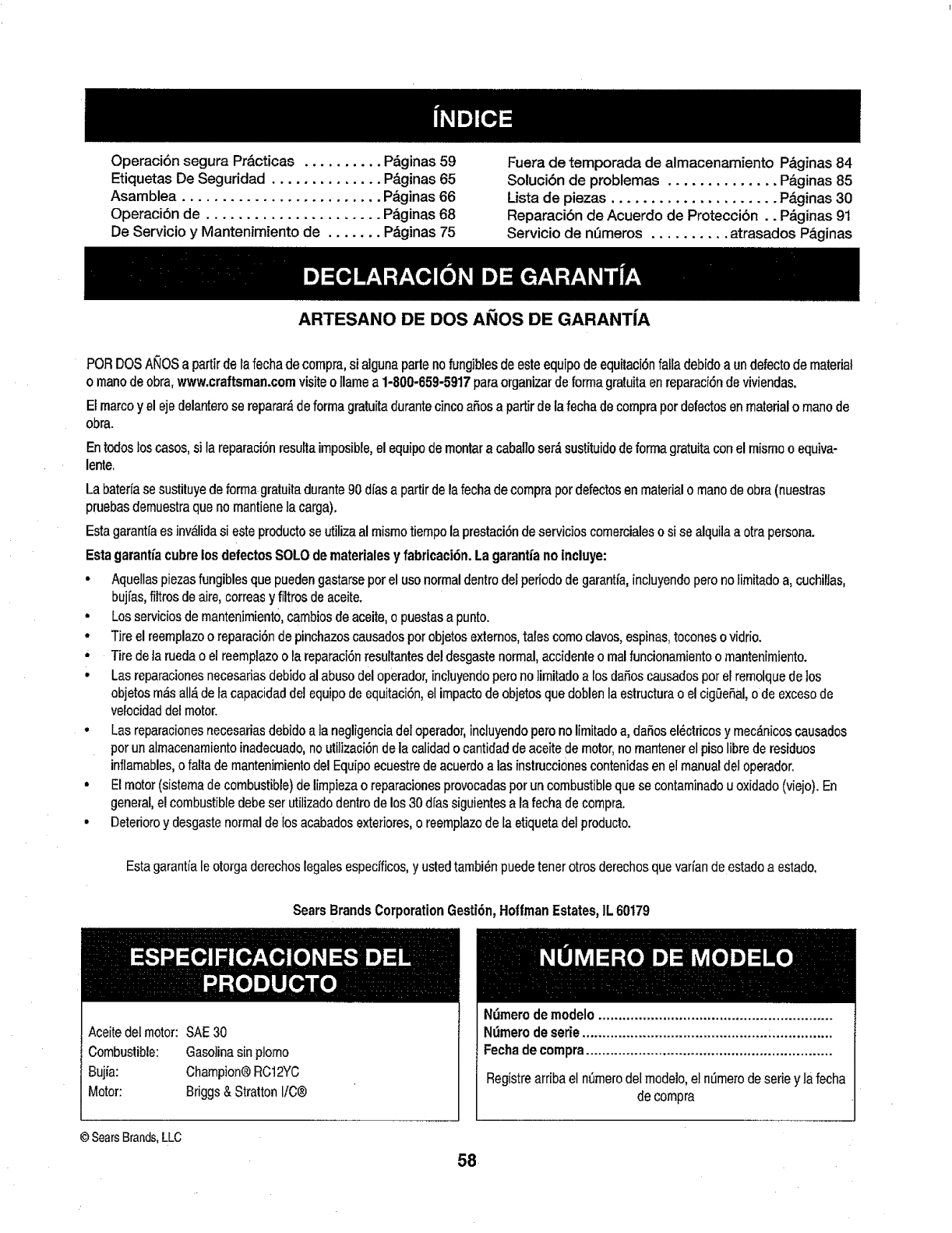
OperaciBn segura Pr&cticas .......... P&ginas 59
Etiquetas De Seguridad .............. P&ginas 65
Asamblea ......................... P_ginas 66
OperaciBn de ...................... P&ginas 68
De Servicio y Mantenimiento de ....... P_ginas 75
Fuera de temporada de almacenamiento P&ginas 84
SotuciBn de problemas .............. P_ginas 85
Lista de piezas ..................... P_.ginas 30
ReparaciBn de Acuerdo de Proteccibn.. P&ginas 91
Servicio de nSmeros .......... atrasados Paginas
ARTESANO DE DOS AI_IOS DE GARANTIA
PORDOSANOSa partirdelafechadecompra,si algunaparlenofungiblesdeesteequipodeequitaciBnfalladebidoaundefectodematerial
o manodeobra,www.craftsman.comvisiteo flamea 1-800-659-5917paraorganizardeformagratuitaenreparaciBndeviviendas.
Elmarcoy el ejedelanterose reparar_deformagratuitadurantecincoaSosapartirdelafechadecornprapordefectosenmaterialomanode
obra.
Entodosloscasos,si lareparaciBnresultaimposible,elequipodernontara cabalioset&sustituidodeformagratuitaconelmismooequiva-
lente.
La baterfase sustituye deforma gratuita durante90 dfasa partir de lafecha de cornprapor defectosen materialo manode obra (nuestras
pruebasdemuestraque no mantienefa carga).
Estagarantfaes invalidasi esteproducto se utilizaal mismo tiempola prestaciSnde servieios comercialeso sise alquilaa otra persona.
Estagarantfacubre los defectos SOLO de materiales y fabricaci6n. La garantiano lncluye:
•Aquellas piezasfungibles que pueden gastarse pot el uso normaldentro def periodo de garantfa, incluyendoperono limitado a, cuchiltas,
bujfas,filtrosde aire, correas y filtros de aceite.
• Losserviciosde mantenimiento,cambiosde aceite,o puestasa punto.
• Tire el reemplazoo reparaciBnde pinchazoscausadospor objetosexternos,tales como clavos,espinas,toconeso vidrio.
•Tire deta rueda o el reemplazoo la reparaciBnresu_tantesde! desgastenormal, accidente o realfuncionamientoo mantenimiento.
• Las reparacionesnecesariasdebido al abuso del operador,inc]uyendoperono ]imitadoa losdaSoscausados pot el remolque delos
objetosm_s all_ deia capacidad del equipode equitaciBn,el impactode objetos que doblen la estructurao el cigeeSal,o de excesode
velocidad del motor.
• Las reparacionesnecesariasdebido a ]a negligencia deIoperador,incluyendopero no IJmitadoa, daSosel_ctricos y mec_nicos causados
porun almacenamientoinadecuado,no utilizaci_nde la calidado cantidadde aceite de motor,no mantenerel pisolibrede residuos
inflamables,o falla de mantenimientodel Equipoecuestre de acuerdo alas instruccionescontenidas en el manualdel operador.
• El motor(sistema decombustible) de limpiezao reparacionesprovocadasporun combustible que se conlaminadou oxidado (viejo). En
general, elcombustible debe ser utilizadodentro de los 30 dfassiguientes a la fecha de compra.
• Deterioroy desgaste normal de losacabados exteriores, o reempiazode la etiqueta del producto.
Estagarantia le otorga derechos legalesespecfficos,y usted tambi_n puedetenet otros derechos quevarian de estado a estado.
SearsBrandsCorporationGestiBn,HoffmanEstates,IL60179
Aceite del motor: SAE 30
Combustible: Gaso]inasin plomo
Buj_a: Champion®RC12YC
Motor: Briggs & Stratton I/C®
© SearsBrands,LLC
NBmerodemodelo ..........................................................
NOmerodeserie.............................................. :...............
Fechadecompra.............................................................
Registreardbaelnt_merodelmodelo,eln_merodeseriey Jafecha
decompra
58
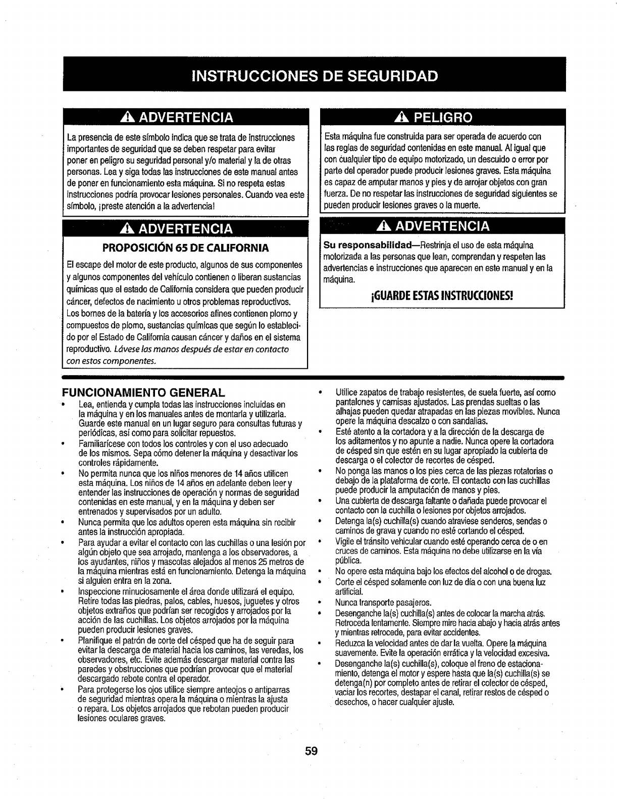
Lapresenciadeestesfmboloindicaquesetratade{nstrucciones
importantesdeseguridadquesedebenrespetarparaevitar
porterenpeligrosu seguridadpersonalylo materialy ladeotras
personas.Leay sigatodaslasinstruccionesdeestemanualantes
deponerenfuncionamientoestam_.quina.Sinorespetaestas
instruccionespodriaprovocarlesionespersonales.Cuandoyeaeste
sfmbolo,ipresteatenci6na laadvertencia!
Estam_quinafueconstruidaparaseroperadadeacuerdocon
lasreglasdeseguridadcontenidasenestemanual.At iguatque
concualquiertipo deequipomotorizado,undeseuidooerrorpot
parle(:teloperadorpuedeproducirlesionesgraves.Estam_quina
escapazdeamputarmanosypiesy dearrojarobjetoscongran
fuerza.Denorespetarlasinstruccionesdeseguridadsiguientesse
puedenproducirlesionesgraveso tamuerte.
PROPOSICION 65 DE CALIFORNIA
Elescape del motorde este producto,algunosde sus componentes
y algunoscomponentes del vehicu]ocontieneno Uberansustancias
qufmicasque el estado de California considera que pueden producir
c_.ncer,defectosde nacimientouotrosproblemas reproductivos.
Losbornes de ta bateria y los accesoriosalines contienen plomoy
compuestosde plomo, sustanciasqufmicasque segen Io estableci-
do por el Estadode Californiacausanc_ncer y dafios enel sistema
reproductivo. L_veselas manos despu_sde estar encontacto
con estoscomponentes.
IIIIIIIIIIIIIIIIIIIIIIIIIIIIIIIIIIIIIIIIIIIIIIIIIIIIIIIIII I II I I III I III III
FUNCIONAMIENTO GENERAL
• Lea, entienda y cumpla todas las instrucciones incluidasen
la m_quina yen los manuaiesantes de montarlay utilizafla.
Guarde este manualen unlugar seguro para consultas futuras y
peri6dicas, asi como para solicitar repuestos.
• Famitiaricesecontodos los controlesy con el uso adecuado
de los mismos. Sepa c6mo detenerla m_.quinay desaetivarlos
controles r_pidamente.
•No permita nuncaque los niSosmenores de 14 afios utilicen
esta m_quina. Losnifios de 14afios en adelante deben leer y
entender las instruccionesde operaci6ny normasde seguridad
contenidas en este manual, yen la m,_quinay debenser
entrenadosy supervisadospor unadulto.
• Nunca permita que los adultosoperen esta m_,quinasin recibir
antes la instrucci6n apropiada.
•Para ayudara evitar elcontacto con las cuchitlaso una lesi6n por
algSnobjeto que seaarrojado,rnantengaa los observadores,a
los ayudantes,ni_5osy mascotasalejados al menos25 metros de
la m_.quinamientras esl_ en funcionamiento.Detengala m_quina
si alguien entra en la zona.
• Inspeccione minuciosamenteel _rea donde utilizar&el equipo.
Retire todas las piedras,palos, cables, huesos,juguetesy otros
objetos extraSosque podrfanser recogidos y arrojadospor la
acci6n de las cuchillas.Losobjetos arrojadospor la m_quina
pueden producir lesiones graves.
•Pianifiqueel patr6n de cortedel c6spedque ha de seguir para
evitar la descargade materialhacia los caminos,lasveredas, los
observadores,etc. Evite adem_.sdescargar material contralas
paredesy obstruccionesque podrian provocarque el material
descargado rebote contrael operador.
•Paraprotegerselosojos utilice siempre anteojoso antiparras
deseguridad mientrasopera la m_,quinao rnientrasla ajusta
o repara. Losobjetos arrojados que rebotanpueden producir
lesionesoculares graves.
Su responsabilidad--Restrinja el usodeesta m_quina
motorizadaalas personasque lean,comprendany respetenlas
adverlencias einstrucciones que aparecenen estemanualyen la
m_quina.
iGUARDEESTASINSTRUCCIONES!
III J
• Utilicezapatosdetrabajo resistentes,de suela fuerte, asf corno
pantalonesy camisas ajustados. Lasprendassueltaso las
alhajas pueden quedar atrapadas en las piezas movibles. Nunca
opere la m_quina descalzo o con sandalias.
•Est_atento ala cortadoray a la direcci6nde la descargade
los aditamentosy no apunte a nadie.Nunca opere la cortadora
decesped sin que est6n ensu lugar apropiado la cubieita de
descargao el colectorde recortes de cesped.
•No pongalas manoso los pies cerca de las piezasrotatoriaso
debajode la plataformade corte,Elcontactocon las cuchillas
puedeproducir la amputaci6nde manosy pies.
•Una cubiertade descargafaltanteo dafiada puedeprovocarel
contactoconla cuchilla o lesionespor objetosarrojados.
• Detengala(s) cuchilra(s)euandoatraviesesenderos,sendaso
caminosde gravay cuandono estecortandoel cesped.
, Vigile el tr_nsitovehicularcuandoest_operandocercade o en
crucesdecaminos.Estam_quinanodebeutilizarseenla via
p_blica.
• Noopere estam_quinabajo losefectosdetalcoholo de drogas.
•Cortee}c_spedsolamenteconluz ded_'ao con unabuenaluz
artificial.
•Nuncatransportepasajeros.
•Desenganchela(s) cuchilla(s)antesde colocarla marehaatr_.s.
Retrocedalentamente.Siempremirehaciaabajoy haciaarrasantes
y mientrasretrocede,paraevitaraccidenles.
• Reduzcala velocidadantes de dar la vue[ta.Operela m_.quina
suavemente.Evite la operaci6nerr_ticay lavelocidadexcesiva.
• Desenganchela(s)cuchilla(s), coloqueel frenodeestaciona-
miento,detengael motory esperehasta quela(s) cuchilla(s)se
detenga(n)por completoantes deretirarel coiectorde c_sped,
vaciarlos recortes,destaparel canal,retirarrestos dec_spedo
desechos,o hacercualquierajusle.
59
• Nuncadeje la m_,quinaenfuncionamientosin vigilanda. Apague
siemprelas cuchillas,coloqueelfrenode mano,detenga el motory
retirela Ilaveantes de bajarsedel vehfculo.
,Tonga sumo cuidado alcargar o descargarla m_quina en un
remolqueo cami6n. Estaunidadno debeconducirse en ascensoo
descensode rampas,porquepodrfaladearsey provocarles/ones
personalesgraves.En las rampasla m_.quinase debeempujar
manuatmenteparacargarlao descargaflacorrectamente.
•Elsilenciadory el motorse calientany puedencausarquemaduras.
No los toque.
•Revise elespacio Iibrepor encimade la cabezaantes de conducir
bajo las ramasbajasde _rbo]es,cables,cerramientosde puertas,
etc.en los cualesel operadorpodfia atorarseo ser empujadofuera
de la m_.quina,]oque podrfaresultarenlesionesgraves.
°Desenganchetodos los embraguesdelos accesoriosy presione
totalmenteelpedal del frenoantesde intentararrancarel motor.
• La m_quinaest,_diseSadaparacortar c6spedresidencialnormal,
conuna alturano mayora 10".No intentecortar c_speddemasiado
crecido,seco (pot ej.,pastura)ni pi]asde hojassecas.E1c_,sped
y las hojassecaspuedenentraren contactoconel escape del
motoryio acumularseenla p]ataformade]acortadora de c_sped,
convirti6ndoseen unpeligrode incendio
•Utflicesofamenteaccesoriosy aditamentosaprobadosparaesta
m,_quinapot el fabricantede la misma.Lea, comprenday siga
todastas instruccionesproporcionadascon los accesorioso
aditamentosaprobados.Paraobteneruna fistade los accesorios
aprobadosy los archivosadjuntos,Ilame1-800-659-5917.
•Losdatos estadfsticosmuestranque losoperadoresde60 aSos
y mayoresseven involucradosen unalto porcentajede lesiones
refacionadascon tractorescoda c6sped.Estosoperadoresdeben
evaluarsu capacidad paraoperaret tractorcorta c_spedenforma
suficientementeseguraparaprotegersea e]losmismosy a los
demos contralesionesgraves.
•Si se presentan situacionesque no est_n previstasen este
manual sea cuidadosoy useel sentido com_n. Contacto 1-800-
659-5917para informaci6ny asistencia.
FUNCIONAMIENTO EN PENDIENTES
Las pendientesson un factorimportanterelacionadocon accidentes
pot derrapey vuelcosque pueden producirlesionesgraves e incluso
la rnuerte. La operaci6nen pendientesrequieremayor precauc[6n.
Si no puede retroceder enla pendienteo si no se siente seguro, no
realice ninguna operaci6n de corte.
Parasu seguridad, useel indicador de pendientesque se incluye
como parte de este manual paramedirla pendienteantes de operarla
m_.quinaen una zona inclinada. Si la pendientees mayor de 15 grados
seg_nel medidor,no opere estam&quinaen esesector,pues podria
causarlesiones graves.
Haga Io siguiente:
• Pode haciaarribay abajo de las pendientes,no de forma trans-
versal. Tengacuidadocuando cambiededirecci6nal operaren
pendiente.
• Est_atentoa los hoyos,surcos,baches,rocas,u otrosobjetos
ocultos.Elterreno desnivetadopuedevoltearla m&quina.Elc_sped
altopuedeocultarobst,_culos.
•Vayaa bajavelocidad.EtijaunavelocidadIosuficientementebaja,
demodoque notengaque detenerseo hacercambiosmientras
est_sobrela pendiente.Losneum,_ticospodrfanperdertracci6n
sobrelaspendientesatin cuandolosfrenosfuncionaranapro-
piadamente.Siempremantengala m_.quinaen cambiomientras
desciendelas pendientes,parepoderfrenarconel motor.
•Sigalas recomendacionesdel fabricanteparalospesoso contra-
pesosdelas ruedas,paramejorarla estabilidaddela m_quina.
Pararecomendaciones,Ilameal 1-800-659-5917.
•Tonga especialcuidadocon los colectoresde c6speduotros
aditarnentos.Losmismospuedenmodificarla estabilidaddela
m_.quina.
•Hagaque todos losmovimientosen laspendientessean tentosy
graduales.Nocambie repentinamentela velocidadnita direcci6n.
Unfrenadoo cambiodeverocidadrepentinospuedencausarque
el frentede lam,_quinase levantey d_ unavolteretahaciaatr_.s,lo
que podrfaproducirlesionesgraves.
•Evitearrancaro detenerseenuna pendiente.Silos neum,_ticos
pierdenla tracci6n,desenganchelascuchillasydescienda
lentamentela pendiente.
No haga to siguiente:
•Nogiresobrelaspendientesa menosque seanecesario.Sies
posible,girelentamentey graduaimenteduranteel descenso.
•Nocorteelc_spedcercade pozos,hundimientoso terraplenes.La
cortadorade c6spedpuedevolcarserepentinamentesiunadetas
ruedasest_sobreel bordedeun acantilado,zanjao si unhordese
desmorona.
,No[ntenteestabilizarla m&quinaponiendoel pieenel suelo.
,Noutiliceuncolectordec_sped enpendientesempinadas.
• Nopodeelc_spedh_medo.Unamenortracci6npodriacausar
derrapes.
•Noparadescender.Elexcesodeveloc[dadpuedehacerqueel
operadorpierdael controldela m&quina,ocasionandolesiones
gravese inclusola muerte.
• Noremolquecargaspesadasdetr_sdelosaditamentos(carritode
basuracargado,podadorade roditlos,etc)enpendientesmayores
de 5 grados.Cuandosedesplazapendienteabajo,elpesoadicional
tiendea empujareltractory puedehacerquesepierdaelcontrol
del mismo(pot ejemplo,el tractorsepuedeacelerar,sereducela
capacidadparafrenary maniobrar,losaccesoriospuedenplegarse
como uncortaplumasy hacerqueeltractorvueique).
NINOS
Puedenocurrir accidentestr,_gicossi eloperador no est,. atentoa la
presencia de niSos.Por logeneral, losniSesse sienten atrafdospot
este tipodem,_quinasy su funcionamiento.No entiendenlos riesgos
ni los peligros. Nuncaasumaque los niSospermanecer_nen el mismo
lugar donde los rio por eltima vez.
• Mantengaa losniSosfueradel _reade trabajoybajoestricta
vigilanciade unadultoresponsableadem_sdel propiooperador.
,Est_alertay apaguela m_quinasiun niSoingresaal_rea.
• Antesy mientrasest_retrocediendo,mirehaciaarrasy cuidequeno
hayaniSos.
•NuncatransporteniSos,alanconlacuchillaapagada.Podrfancaerse
y resultarseveramenteheridoso interferircon laoperaci6nsegurade
lam_quina.
•Tengaextremaprecauci6ncuandoseaproximea esquinasciegas,
portales,arbustos,&rbolesu otrosobjetosquepuedanimpedirlever
a un niSoque secruceen el recorridode ta m_quina.
60
° Paraevitaracoidentesaloperarenmarchaatr_s,siempredesengan-
chelascuchillasantesde colocarmarchaatr,_s.Siest_instalado,
el"ModoPrecauei6nMarchaAtr&s"(hojasde operarla m_quina,
mientrasque lospaseosa lainversa)nodebeuUlizarsecuandohay
nifiosu otraspersonaspresentes.
• Mantengaa losnifios alejadosdelos motoresenmarchao calientes.
Puedensufrirquemadurascon unsilenciadorcaliente.
,Retirela llavecuandodejelam,_quinasinvigilancia,evitequeuna
personasin autorizaci6nla maneje.
No perrnitanunca que losnifios menoresde 14afios utilicenesta
m_.quina.Losnifios de 14afios en adelantedeben leer y entender las
instnJccionesde operaci6ny normas de seguridadeontenidasen este
manual,yen la m_quinay deben ser entrenadosy supervisadospot
unadulto.
REMOLQUE
° Remolque_nicamenteconuna m_,quinaquecuentecon un
enganchedisefiadopararemolcar.Noacopleequiporemolcado
exceptoenel puntodeenganche.
• Sigalasrecomendacionesdelfabricanteenloque respectaa _os
limitesdepesodelos equiposa remolcary alremolqueenpendien-
tes. Pararecomendaciones,flameat 1-800-659-5917.
• Nuncapermitala presenciade nifios uotraspersonasdentroo sobre
los equiposremotcados.
• En taspendientes,el pesodel equiporemolcadopuedecausar
p_rdidade tracci6ny p_rdidadecontrolde la m_quina.
, Siempreuseextrala precauci6nremolcandoconunam_quina
capazde hacervueltasapretadas(p.ejpaseo"devueltacero'- en el
cortac_sped).Hagaampliasvue]tasparaevitaralgato-knifing.
• Despl_ceselentamenteydejedistanciaadicionalparafrenado.
• Noparadescender.
SERMlClO
Manejo seguro de la gasolina
Paraevitar lesiones personaleso dafios materialessea sumamente
cuidadosoal manipular la gasolina.La gasolinaes sumamente
inftamabley sus vapores pueden causar explosiones.Se puede
lesionargravementesi derrama gasolinasobre usted osobre la ropa,
ya que _stase puede incendiar. L_vesela piel y c_mbiesede ropa de
inmediato.
• Utilice s61olos recipientes paragasolina autorizados.
• Nunca Ilene los recipientesen et interiorde un vehiculoo cami6n
o caja de remolquecon recubrimientopl_.stico.Coloquesiempre
los recipientesen el piso y lejos del vehicu]oantes de realizarla
carga
• Cuandosea factible, retireel equipoa gasolina del cami6n o
remolquey 116neloen el sue]o.SI estono es posible, lleneel
equipoen un remolque conun contenedorport&ti],en vez de
hacerto con una boquilla dispensadora de gasolina.
• Mantenga taboquilla de llenad0en contactocon el borde del
depbsitode combustible o con Ia abertura de] recipienteen todo
momento,hasta terminar la carga. No uUliceundispositivo de
boquilla deapertura/cierre.
• Apaguetodosloscigarrillos,cigarros,pipasy otrasfuentesde
combusli6n.
• Nuncacarguecombustibleenlam_quinaenunespaciocerrado.
° Nuncasaquelatapadelcombustibleni agreguecombustible
mientraselmotorest_calienteo enmarcha.Dejequeelmotor
seenfrieporIo menosdosminutosantesdevolveracargar
combustible.
° NuncaIleneenexcesoeldep6sitodecombustible.Lleneel
tanquenom_.sde½ pulgadapordebajodelabasedelcuello
deltap6ndecarga,paradejarespacioparalaexpansi6ndel
combustible.
• Vuelvaa colocarlatapadelagasolinay aj_stelabien.
, Limpiee]combustiblequese hayaderramadosobreelmotory el
equipo.Trasladelam&quinaaotrazona.Espere5 minutosantes
deencenderelmolor.
• Parareducirelriesgodeincendio,mantengalam_.quinalimpia
depasto,hojasy deacumulaci6ndeotrosresiduos.Limpielos
derrarnesdeaceiteocombustibley saquetodoslos residuos
embebidosdecombustible.
• NuncaguardeIam_quinaoel recipientedecombustibleenun
espaciocerradodondehayafuego,chispaso luzpiloto,como
pot ejemplodecarentadoresdeagua,calefactoresdeambientes,
hornos,secadoresderopauotrosaparatosa gas.
• Dejequelam,_quinaseenfriecincominutospot 1omenosantes
deguardarta.
Serviciogeneral
• Nuncaenciendael motorenespacioscerradoso enunazona
conpocaventilaci6n.Elescapedelmotorcontienemon6xidode
carbono,ungasinodoroy letal.
• Antesdelimpiar,repararoinspeccionarla m_quina,compruebe
quela(s)cuchilla(s)y todasIaspartesenmovimientose hayan
detenido.Desconecteelcabledela bujfay p6ngalohaciendo
masacontrael motorparaevitarqueseenciendaaccidental-
mente.
• Revisepefi6dicamenteparaasegurarsequelascuchillasse
detenganporcompletoenaproximadamentecinco(5)segundos
despu_sdeaccionarel controldedesenganchedela(s)
cuchi]la(s).Silascuchillasnosedetienendentrodeestelapso
detiempo,suunidaddeber_serreparadaporsudistribuidorde
servicioautorizadoMTD.
• Reviseconfrecuenciae!funcionamientodelsistemadefrenos
ya queest,_sujetoadesgasteporlaoperaci6nnormat.Ajustey
efeet_emantenimientosegOnse requiera.
61
Revise los pernosde montaje de la(s) cuehiIta(s)y del motor a
intervalosfrecuentes paraverificarque est_n bienapretados.
Adem_.s,inspeccione visualmente la(s) cuchilla(s)en buscade
dafios (por ejemplo, desgasteexcesivo,abolladuras, rajaduras,
etc.). Reemplacela(s) cuchilla(s) enicamenteconlas cuchillas
defabricantesde equipos originales(O.E.M.) listadasen este
manual. Etuso de piezasque no cumplen con las especifi-
cacionesdeI equipooriginal podrla Ienercomoresultadoun
rendimientoincorrectoy adem_s poner en riesgo la seguridad.
Lascuchillasde laspodadoras son muyafiladas. EnvuelvaIa
cuchilla o utiIice guantes y extreme las precaucionescuando
efectSemantenimiento.
Mantengatodos los pernos, tuercas y tornillos bienajustados
paraasegurarsedeque la m,_quinase encuentra en condiciones
seguras de operaci6n.
Nuncaaltereel sistema de enclavamientode seguridadni
otros mecanismosde seguridad.Controle peri6dicamenteque
funcionen correctamente.
Despu_sde golpear con alg_n objeto extraSo,detengaeI motor,
desconecteel cable de la bujfa y conecteel motora masa.
Inspeccioneminudosamente la m,_quinapara versi est,.daSada.
Repareel dafio antes de arrancar y utifizarla m_.quina.
Nuncatrate de hacer ajusteso reparacionesa la m,_quina
mientrasel motor est,, en marcha.
Loscomponentesdel colectorde c6sped y la cubierta de
descarga,est,_nsujetos a desgaste y daSosque podrfan dejar
expuestaspartesen movimientoo permitir que se arrojen objetos.
Paraprotegersu seguridad, verifiquefrecuentementetodos los
componentesy reempl_celosinmediatamentes61oconpiezas de
los fabricantes del equipo original, listadosen este manual.El uso
de piezasque no cumplen conlas especificacionesdel equipo
originalpodria tenet como resultadoun rendimientoincorrectoy
adem&sponeren riesgo laseguridad.
No cambiela configuraci6n delregulador del motorni 1oopere
a sobrevelocidad.El reguladordel motorcontrola iavelocidad
rn_ximasegura de funcionarniento del motor.
Mantengao reemplacelas etiquetas deseguridad e instrucciones
seg_nsea necesario.
Respetelas norrnasreferentesa la disposici6n correctay las
reglarnentacionessobre gasolina,aceite, etc.para proteger el
medioambiente.
Seg0nIa Comisi6n de Seguridadde Productos para et Consu-
midorde los EstadosUnidos (CPSC)y ta Agencia de Protecci6n
Ambientalde los Estados Unidos (EPA),este productotiene una
vida _til media de siete (7) aSos,6 270 horasde funcionamiento.
AI finalizarla vida _til media,adquiera una m_quina nuevao haga
inspeccionaranualmente t_staSearspot uno u otrodistribuidorde
serviciospara cerciorarsede que todos los sistemas mec_nicos
y deseguridadfuncionan correctamentey no tienen excesivo
desgaste.Si no ]o hace, pueden producirseaccidentes, Iesiones
o rnuerte.
NO MODIFIQUE EL MOTOR
Paraevitar lesiones graveso la muerte,no moditique el motor bajo
ningunacircunstancia.Si cambia la configuraci6ndel regulador del
motor elmotor puededescontrolarsey operara velocidadesinsegu-
ras. Nuncacambie la configuraci6nde f&bdcadel reguladordel motor.
AVISO REFERIDO A EMISIONES
Losmotoresque est&ncertificados y cumplencon las regulaciones
de emisionesfederales EPAy de California paraSORE (Equipos
pequehos todoterreno) est_.ncedificados paraoperar congasolina
cornen sin plomo y pueden incluir lossiguientes sistemas de control
de emisiones: Modificaci6nde motor (EM) y catalizadorde tres vfas
(TWC)si est_,nequipadosde esa manera.
GUARDAOHISPAS
Estam_quina est_ equipada conun motordecombusti6n internay
nodebe set utilizadaen o cerca de unterreno agreste cubierto por
bosque,matezaso hierbaexceptosi el sistemade escapedel motor
est_equipadocon un amortiguador dechispas que cumplacon las
leyeslocales o estatalescorrespondientes,encaso de haberlas.
Si se utiliza un amortiguadorde chispasel operadorIo debernantener
en condicionesde usoadecuadas. En el Estadode California las
medidas anteriormentemencionadas sonexigidaspor ley (Articulo
4442 del C6digo de Recursos P0blicosde California). Es posible
que existan leyessimilares en otrosestados.Las leyes federalesse
aptican enterritoriosfederales.
Puedeconseguir el amortiguadorde chispaspara el silenciadora
tray,s de su distribuidorautorizadode motoreso poni_ndose en
contacto con el centro de servicioSears.
62
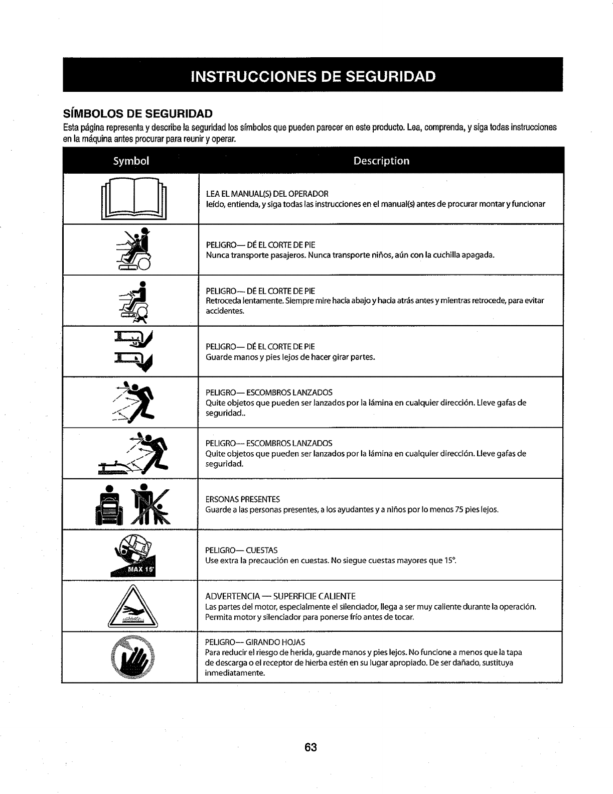
SJMBOLOS DE SEGURIDAD
Estap_ginarepresenlay describelaseguridadlossfmbolosquepuedenparecerenesteproducto.Lea,comprenda,y sigatodasinstrucciones
enla m_quinaantesprocurarparareuniry operar.
O
, ,,,,,,,, ,,
:4
LEA ELMANUAL(S) DEL OPERADOR
leido, entienda, y siga todas las instrucciones en el manual(s) antes de procurar montar y funcionar
PEUGROw DI_EL CORTEDE PIE
Nunca transporte pasajeros. Nunca transporte nifios, a_n con la cuchilla apagada.
PELIGRO-- DE EL CORTEDE PiE
Retroceda tentamente. Siempre mire hacia abajo y hacia atr&s antes y mientras retrocede, para evitar
acddentes.
,,, ,, ,, ,, ,,,,,,,,, ,,,,,,,
PEL]GRO-- DI_ELCORTE DE PIE
Guarde manos y pies lejos de hacer girar partes.
PELIGRO-- ESCOMBROSLANZADOS
Quite objetos que pueden ser lanzados pot la I&mina en cualquier direcci6n. Lleve gafas de
seguridad..
PELIGRO-- ESCOMBROSLANZADOS
Quite objetos que pueden ser lanzados por la I_mina en cualquier direcci6n. Lleve galas de
seguridad.
ERSONASPRESENTES
Guarde alas personas presentes, a los ayudantes y a nifios pot to menos 75 pies lejos.
PELIGRO-- CUESTAS
Use extra la precaudOn en cuestas. No siegue cuestas mayores que 15°.
ADVERTENCIA -- SUPERFICIE CALIENTE
Las partes del motor, especialmente el si]enciador, l]ega a ser muy caliente durante la operaci6n,
Permita motor y silenciador para ponerse frio antes de tocar.
% PEUG.O--Gi.ANOO.OJAS
_ _ _ Para reducir el riesgo de herida, guarde manos y pies lejos. No funcione a menos que la tapa
_ _ de descarga o el receptor de hierba est6n en su lugar apropiado. De ser dafiado, sustituya
_'_ inmediatamente.
63
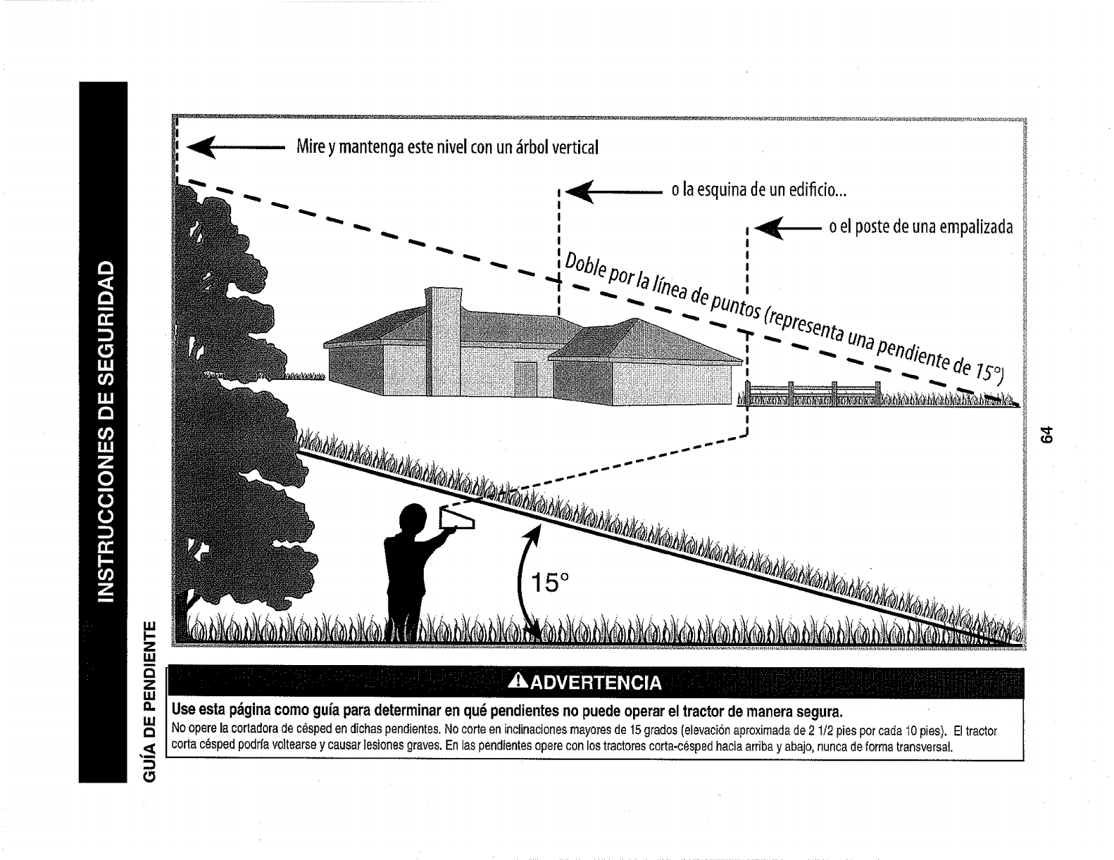
_4 Mireymantengaestenivelconun_rbolvertical
2
I,I,I
olaesquinadeunedificio...
oelpostedeunaempalizada
15°
Useestapdginacomogufaparadeterminaren qu_pendientesno puede operarel tractorde manera segura.
Nooperelacortadoradec_spedendichaspendientes.Nocorteeninclinacionesmayomsde15grados(elevaci0naproximadade2 1/2piesporcada10pies). Eltractor
cortac_spedpodrfavo]tearsey causar]esionesgraves.Enlaspendientesopereconlostractorescorta-c6spedhaciaarribay abajo,nuncadeformatransversal.
(D
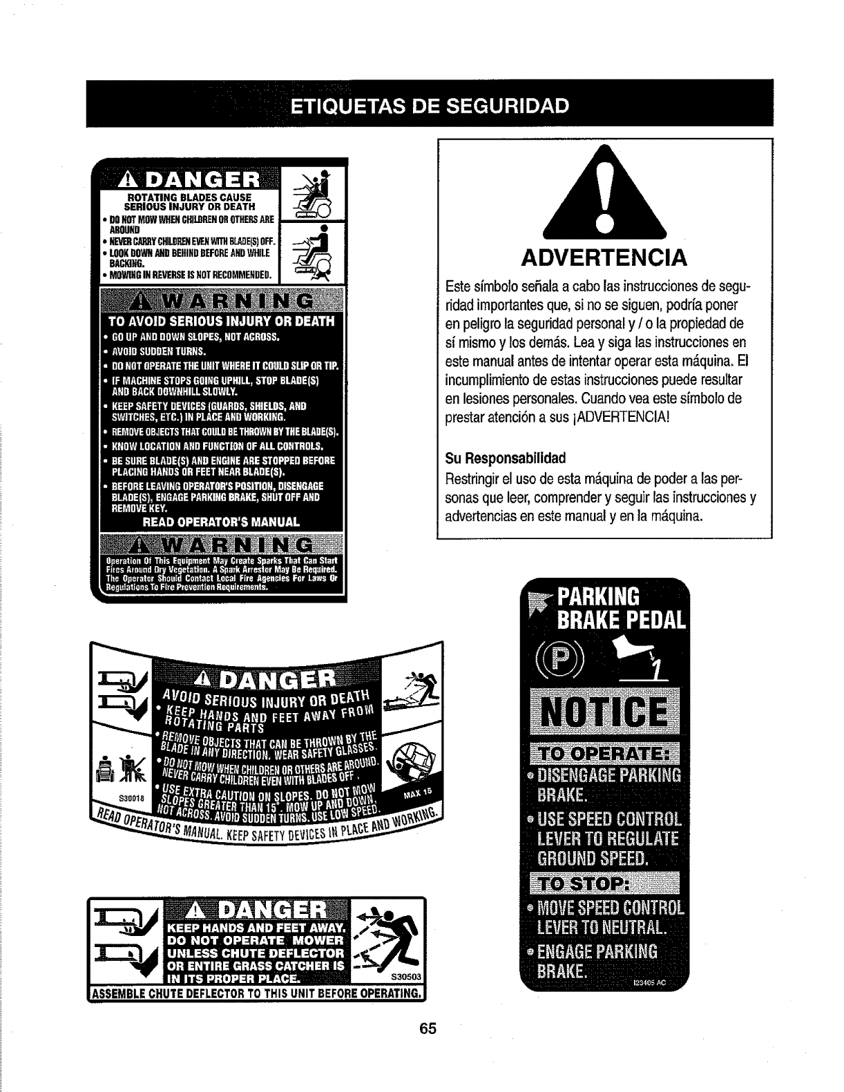
ROTATING BLADESCAUSE
SERIOUS INJURY OR DEATH
•DONOTMOWWHENCHILDRENOROTHERSAREi
AROUND
•tEV1ERCARRYC_ E_..NWITHBL_E(S)OFF.
• LOOKDOWNANDBEHINDBEFOREANDWHILE
BACIOHG.
• MOWINGINREVERSEISHOTRECOMMENDED. ADVERTENCIA
Este s{mbolo seSala a cabo las instruccionesde segu-
ridad importantes que, si no se siguen, poddaponer
en peligro la seguridad personal y /o la propiedad de
s( mismo y los demos. Lea y siga las instrucciones en
este manual antes de intentar operar esta m_.quina. E!
incumplimiento de estas instrucciones puede resultar
en lesiones personales. Cuando vea este sfmbolo de
prestar atenci6n a sus iADVERTENCIA!
Su Responsabilidad
Restringir el uso de esta m_quina de poder alas per-
sonas que leer, comprender y seguir las instrucciones y
advertencias en este manual yen la m_quina.
65
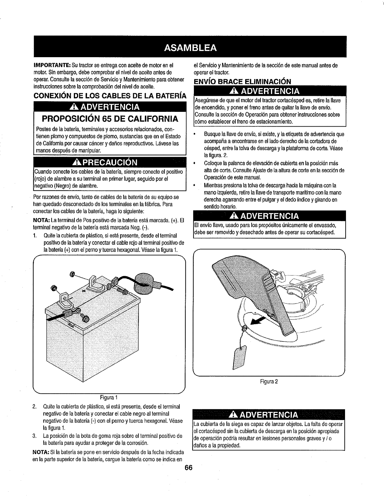
IMPORTANTE: Sutractor se entregacon aceite de motoren el
motor. Sin embargo,debe comprobar el nivel de aceiteantes de
operar.Consulte la secci6n de Servicio y Mantenimientoparaobtener
instruccionessobre la comprobaci6n del nivel de aceite.
CONEXlON DE LOS CABLES DE LA BATERfA
PROPOSICION 65 DE CALIFORNIA
Postesde]a baterfa,terminalesy accesodosrelacionados,con-
tienenplomoy compuestosdeplomo,sustanciasqueen elEstado
deCaliforniaporcausarc_ncery daSosreproductivos.L_veselas
manosdespu_sdernanipular.
Potrazones de envfo,tanto de cables dela batedade su equipo se
han quedado desconectadode los terminalesen la f_.brica.Para
conectar los cables de la baterfa,hagato siguiente:
NOTA: Laterminal de Pos positivode la batefia est_marcada. (+). El
terminal negativode la baterfaest_ marcada Neg. (-).
1. Quitela cubiertade pl,_stico,siest_presente,desdeel terminal
positivodela baterfay conectarel cablerojo alterminal positivode
la baterfa(+)con el pernoytuerca hexagonal.V_ase laligura 1.
,.. j
Figura1
2. Quite la cubierta de pl_stico,si est_ presente,desde e]terminal
negativode la bateda y conectar el cable negro al terminal
negativo dela bateria (-) con el pemo y tuerca hexagonal.V_ase
la figura 1.
3. La posici6n dela bota degoma roja sobre el terminalpositivo de
la baterfaparaayudar a protegerde la corrosi6n.
NOTA: Si la bater/ase pone en servicio despu6sde la fecha indicada
en la parte superiorde la bateda,cargue ]a baterfacomo se indica en
elServicioy Mantenimientodelasecci6ndeestemanualantesde
operareltractor.
ENVfO BRACE ELIMINACI6N
irelaIlave
]deencendido_uitar laIlavedeenvio.
]C_ obtenerinstruccionessobre
]_stacionamiento.
•BusquelaIlavedeenv¿o,siexist&y laetiquetadeadvertenciaque
acompaSaaencontrarseenelladoderechodelacortadorade
c_sped,entrelatolvadedescargay laplataformadecorte.V6ase
la figura.2.
o Coloquelapalancadeelevaci6ndecubiertaenlaposici6nm_s
altadecorte.ConsulteAjustedelaalturadecorteenlasecci6nde
Operaci6ndeestemanual.
° Mientraspresionalatolvadedescargahacialam_quinaconla
manoizquierda,retirelaIlavedetransportemaritimoconlamano
derechaagarrandoentreelpulgary eldedo|ndicey girandoen
sentidohoratio.
Figura2
Lacubiertadelasiegaescapazdelanzarobjetos.Lafaltadeoperar
elcortac6spedsin lacubiertadedescargaen[aposici6napropiada
deoperaci6npodr[aresultarenlesionespersonalesgravesy /o
da_osata propiedad,
66
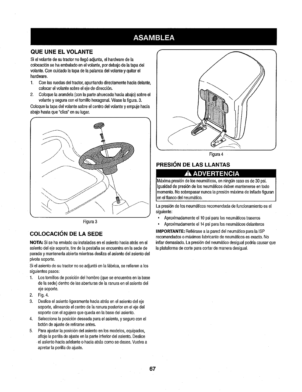
QUE UNE EL VOLANTE
Si el volantede sutractorno Ileg6adjunta,ethardwarede _a
colocaci6nseha embaladoen el volante,pordebajodela tapa del
volante.Con cuidadolatapa de lapalancadel volantey quitar el
hardware.
1. Con las ruedas del tractor, apuntando directamentehaciadelante,
colocar el volante sobreel e]e de direccf6n.
2. Coloque la arandela(con la parle ahuecada haciaabajo) sobre el
volantey segura con eltornillo hexagonal V_ase lafigura. 3.
Coloquela tapa del volantesobre el centrodel volante y empuje hacia
abajo hasta que °clics_en su lugar.
Figura3
COLOCACION DE LA SEDE
NOTA: Si se ha enviadosu instaladasen el asientohacia arrasen el
asiento del eje soporle, tire de ta pestaSase encuentra en la sede de
parada y mantenerla abierta mientras desliza el asientodel asientodel
pivote soporte.
Si el asiento de su tractor nose adjunt6 en Iaf,_brica,se retierena los
siguientespasos:
1. Lostornillos de posici6n del hombro (que se encuentra en la base
de la sede) dentro delas aberturas de ]a ranuraen el asiento del
eje soporte.
2. Fig. 4.
3. Deslice el asientoligeramentehacia atr_s en el asiento del eje
soporte,alineando el centrode la ranura posterioren el eje del
soporte con el agujeroque queda en la base del asiento.
4. Seleccionela posici6ndeseada parael asiento, y seguro con el
bot6nde ajuste de retirarse antes.
5. Para ajustarla posici6ndel asientoen los modelos,equipados,
afloje la perilla de ajuste enla parle inferior del asiento.Deslice
elasiento haciaadelante o hacia atr,_scomo se desee.VueJvaa
apretar la perilla deajuste.
f
\\
Figura 4
PRESION DE LAS LLANTAS
La presi6nde los neumdticos recomendadade funcionamientoes el
siguiente:
• Aproximadamenteel 10psi para los neum,_ticostraseros
• Aproximadamenteel 14 psi pararosneum_.ticosdelanteros
IMPORTANTE: Refi_rasea la pareddel neum_tico parala ISP
recornendadoso maxirnosfabricantede neum&ticoses exacto.No
inflar demasiado.Lapresi6n del neum_ticodesigualpodria causarque
la plataformade corte paracortar de maneradesigual.
67
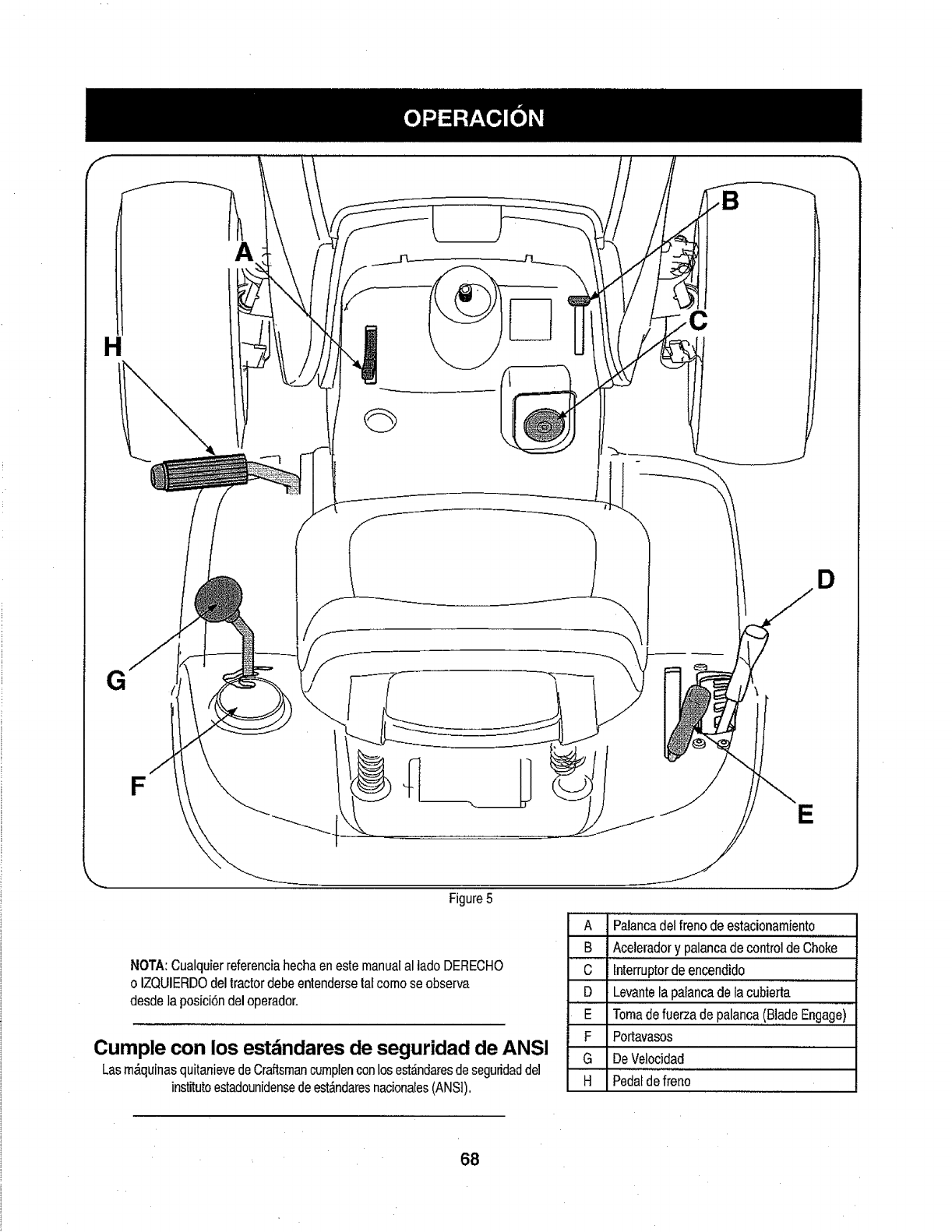
A
H
D
E
Figure 5
NOTA: Cualquierreferenciahechaen este manualal lado DERECHO
o IZQUIERDOdel tractor debe entendersetafcomo se observa
desde la posici6n del operador.
Cumple con los est_ndares de seguridad de ANSI
Las m_quinas quitanievedeCraftsmancumplenconlosest_indaresde seguridadde]
institutoestadounidensedeest_.ndaresnacionales(ANSI),
A Palancadel freno de estacionamiento.............
B Ac,e,l,e,radory palancade controlde Choke
Clnterruptorde encendido
D Levantela palanca de la cubierta
ETomadefuerza de palanca,,,(B,!adeEngage)
FPortavasos
G DeVelocidad
H Pedalde freno
68
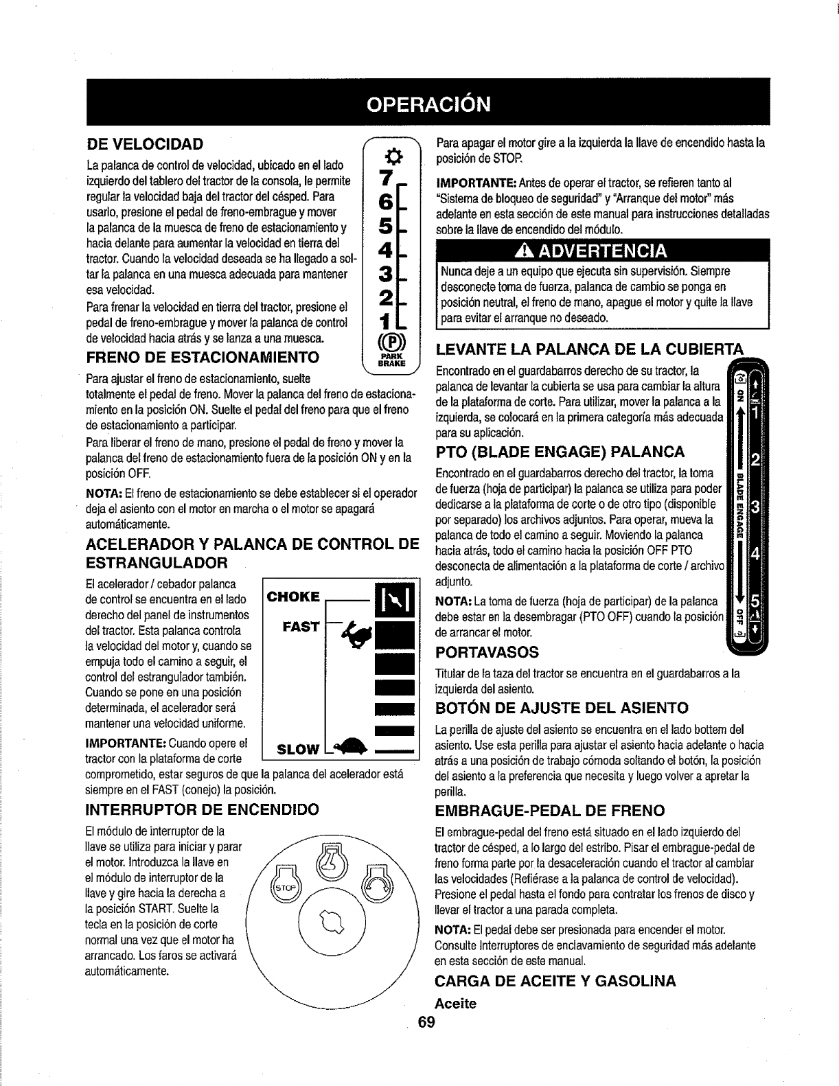
DE VELOClDAD
Lapalancadecontroldevelocidad,ubicadoenellado
izquierdodeltablerodeltractordelaconsola,leperrnite
regularlavelocidadbajadeltractordelc_sped.Para
usarlo,presioneelpedaldefreno-embraguey mover
lapalancadelamuescadefrenodeestacionamientoy
haciade]anteparaaumentarlavelocidadentierradel
tractor.Cuandolavelocidaddeseadase haIlegadoa sol-
tar lapalancaenunamuescaadecuadaparamantener
esavelocidad.
Parafrenarlavelocidadentierradeltractor,presioneel
pedaldefreno-embraguey moverlapalancadecontrol
develocidadhaciaatr,_sy selanzaa unamuesca.
FRENO DE ESTACIONAMIENTO
O
Paraajustar el freno de estacionarniento,suelte
totalmenteel pedal de freno. Moverla palancadel freno de estaciona-
miento en la posici6n ON. Suelteel pedaldel freno paraque el freno
de estacionamientoa participar.
Paraliberarel freno de mano, presioneel pedal de frenoy moverta
palanca delfreno de estacionamientofuera deta posici6n ONyen la
posici6n OFE
NOTA: Elfreno de estacionamientose debeestablecersi el operador
deja el asiento con el motor en marcha o el motor se apagar_
autom_ticamente.
ACELERADOR Y PALANCA DE CONTROL DE
ESTRANGULADOR
Etacelerador/cebador palanca
decontrol se encuentra en el lado
derechodel panelde instrumentos
del tractor. Esta palanca controla
ta velocidad del motory, cuandose
empujatodo el caminoa seguir,el
controldel estranguladortambi_n.
Cuandose pone en una posici6n
deterrninada,el aceleradorser,_
rnantenerunavelocidad uniforme.
CHOKE
FAST
m
IMPORTANTE: Cuandoopereel SLOW
tractor con la plataforrnade corte
comprometido,estar segurosde que la palancadel aceleradorest_
siempre enel FAST(conejo)la posici6n.
INTERRUPTOR DE ENCENDIDO
_ 1t, ......._
Elrn6dulo de interruptorde la
]lavese utiliza parainiciar y parar
el motor.Introduzca la Ilaveen
el mbdulode interruptor dela
flare y gire hacia la derecha a
la posici6n START.Suelte la
tecla en la posici6n de corte
normaluna vez que el motor ha
arrancado. Los faros se activar_
autom_ticarnente.
ParaapagarelmotorgirealaizquierdalaIlavedeencendidohastala
posici6ndeSTOE
IMPORTANTE:Antesdeoperareltractor,se refierentantoal
°Sistemadebloqueodeseguridad"y"Arranquedelmotor_m&s
adelanteenestasecci6ndeestemanualparainstruccionesdetalladas
sobrelailavedeencendidodelm6dulo.
Nuncadejeaunequipoqueeiecutasinsupervisi6n.Siernpre
desconectetornadefuerza,palancadecarnbiosepongaen
posici6nneutral,elfrenodemano,apagueelmotory quitelaIlave
paraevitarelarranquenodeseado.
LEVANTE LA PALANCA DE LA CUBIERTA
Encontradoen el guardabarrosderechode su tractor, la
palancade levantarta cubierta se usa para cambiar laaltura
de la plataformade corte. Parautilizar,moverla palancaa la
izquierda,se colocar_ enla prirneracategorfa m_sadecuada
parasu aplicaci6n.
PTO (BLADE ENGAGE) PALANOA
Encontradoen el guardabarrosderechodet tractor, la toma
defuerza (hojade participar) la paiancase utiliza parapoder
dedicarsea taplataformade corteo de otro tipo (disponible
per separado)losarchivos adjuntos, Paraoperar, muevala
palancade todo et caminoa seguir.Moviendo la palanca
haciaatr_s, todo el camino hacia fa posici6n OFFPTO
desconectade alimentaci6na la plataforrnade corte/ archivo
adjunto.
NOTA, Latorna defuerza (hoja de participar) de la palanca
debe estaren ladesembragar(PTO OFF) cuando la posici6n
de arrancarel motor.
PORTAVASOS
Titular de lataza del tractorse encuentra en el guardabarrosa la
izquierda delasiento.
BOTON DE AJUSTE DEL ASlENTO
Laperillade ajuste del asientose encuentra enel lado bottem del
asiento.Use esta perillapara ajustarel asiento haciaadelante o hacia
arrasa una posici6nde trabajo c6moda soltando el bot6n,la posici6n
del asientoa la preferenciaque necesita y luego volvera apretar la
perilla.
EMBRAGUE-PEDAL DE FRENO
Elernbrague-pedaldel freno est&situado en el lado izquierdodel
tractor de c_sped, a Io largo del estribo. Pisar el ernbrague-pedalde
freno forma parlepor la desaceleraci6ncuando el tractor al carnbiar
las velocidades(Refi_rase a ]a palancadecontrol develocidad).
Presioneel pedalhastael fondo paracontratar losfrenos de disco y
Ilevarel tractor a una parada completa.
NOTA: Elpedal debe ser presionada paraencender el motor.
Consulte lnterruptoresde enclavamientode seguridadrn_sadelante
en estasecci6n de estemanual.
CARGA DE ACEITE Y GASOLINA
Aceite
69

IMPORTANTE:Sutractorseenvfaconaceiteenelmotor.Sin
embargo,ustedDEBEconlrolare!niveldeaceiteantesdehacerlo
funcionar.Yealasecci6n"Servicioy Mantenimiento"+
Gasolina
Tengamuchocuidadoal trabajarcongasolina.Lagasolinaessuma-
menteinflamableysusvaporespuedencausarexplosiones.Nunca
carguecombustibleenlam;_quinaenunespaciocerradoocuandoel
motorestdcalienteo enmarcha.Apaguecigarri]!os,cigarros,pipasy
otrasfuentesdecombusti6n.
NOTA:CompregasolinaenpequeSascantidades.Nousegasolina
quehayaquedadodelatemporadaanterior,paraminimizarla
formaci6ndedep6sitosdegomaenelsistemadecombustible.
+Estemotorest,,habilitadoparafuncionarcongasolinasinplomo+
Paraobtenerel mejorresultado,Ileneel dep6sitodecombustible
dnicamentecongasolinasinplomolimpiay fresca,enunsurtidor
queindiqueunoctanajeiguala87oads.
• Elgasohol(hasta10%dealcoholetilico,90%degasolinasin
plornoporvolumen)esuncombustibleaprobado.Noseaprueba
elusodeotrasmezclasdegaso]ina/alcoho!,comoE85.
°Et_termetflicoterciario-butflico(MTBE)ylasmezdasde
gasolinasinplomo(hastaunm,'_xirnodet5% deMTBEpot
volurnen)soncombustiblesaprobados.Noseapruebaelusode
otrasmezclasdegasolinai_ter.
• Llenarel dep6sitodecombustibleafaimlibreoentugarbien
ventilado.
•NuncaIleneenexcesoeldep6sitodecombustible.Lleneel
tanquenom,'_sde_ pulgadapotdebajodelabasedelcuello
deltap6ndecarga,paradejarespacioparaIaexpansi6ndel
combustible.
•Nuncasaquelatapadelcombustibleni agreguecombustible
mientraselmotorest&calienteo enmarcha.Dejequeelmotor
se enfrieporIomenosdosminutosantesdevolvera cargar
combustible.
• Limpieelcombustiblequesehayaderramadosobreelmotory el
equipo+Traslade]ama.quinaaotrazona.Espere5 minutosantes
deencenderelmotor.
t. Enciendaelmotorapagadoy dejarqueenfrfeelmotorpor]o
rnenos2minutosantesdequitarlatapadelcombustible.Eltanque
degasolinaest_debajodelguardabarrostrasero,y eltap6nde
Ilenadodecombustibleseencuentraenelcentroclefguardabarros
trasero.Eltap6ndelcombustibleest,.amarradoaltractorpara
impedirquesepierda.Nointenteretirare]tap6ndeltractor.
2. Llenareldep6sitodecombustibleconlagasolina.
VuelvaainstalarIatapadelcombustible.
VfY. I=- vj:4 | :4
NOTA:Eltractorest_equipadoconunatapadeatado,combustible
trinquete.DejedeIlenareltanqueunavezqueel combustiblees
vistodentrode]abocade Ilenado.Estoaseguraqueunaexpansi6n
detvolumenadecuadosecrea1ocontrario,elcombustiblesepuede
derramarlacreaci6ndeunasituaci6npeligrosa.NOrernatare]tanque
decombustible.V_ase]afigura+6. 70
Figura 6
Evite tesiones personales graves o la muerte
,Enlas pendientesconduzcahaciaarriba y hacia abajo,
no de forma transversal
• Evitemaniobrasde giro bruscas.
•No opere la unidaden dreas donde puede derraparo
ladearse.
• Si la m_.quinadejade subir la pediente detenga las
cuchi]lasy retrocedalentamente bajandola pendiente.
• No corteel c_sped cuando haya niSosu otras
personascerca.
• Nuncatransportenihos, ni siquierasi las cuchilias
est,_ndesconectadas.
• Mire haciaabajo y haciaatr_.santes y mientras opera
en marcha atr&s.
• Mantengatodos los dispositivosde seguridad
(protecciones,escudose interruptores)ensu lugar y
encorrectofuncionamiento.
•Retirelos objetos que puedanset arrojados por las
cuchillas en cuaiquierdirecci6n.
•Conozcala ubicaci6nyfunci6n detodos loscontroles.
•Aseg_resede que las cuchiltasy el motor se detengan
antes de colocar las manoso los pies cerca de las
cuchillas.
•Antes deabandonar la posici6ndel operafor,dejar de
tractor,desenganchelas cuchillas,coloque el freno de
mano,apague el motory retire la Ilave.
Lea el manual del operador
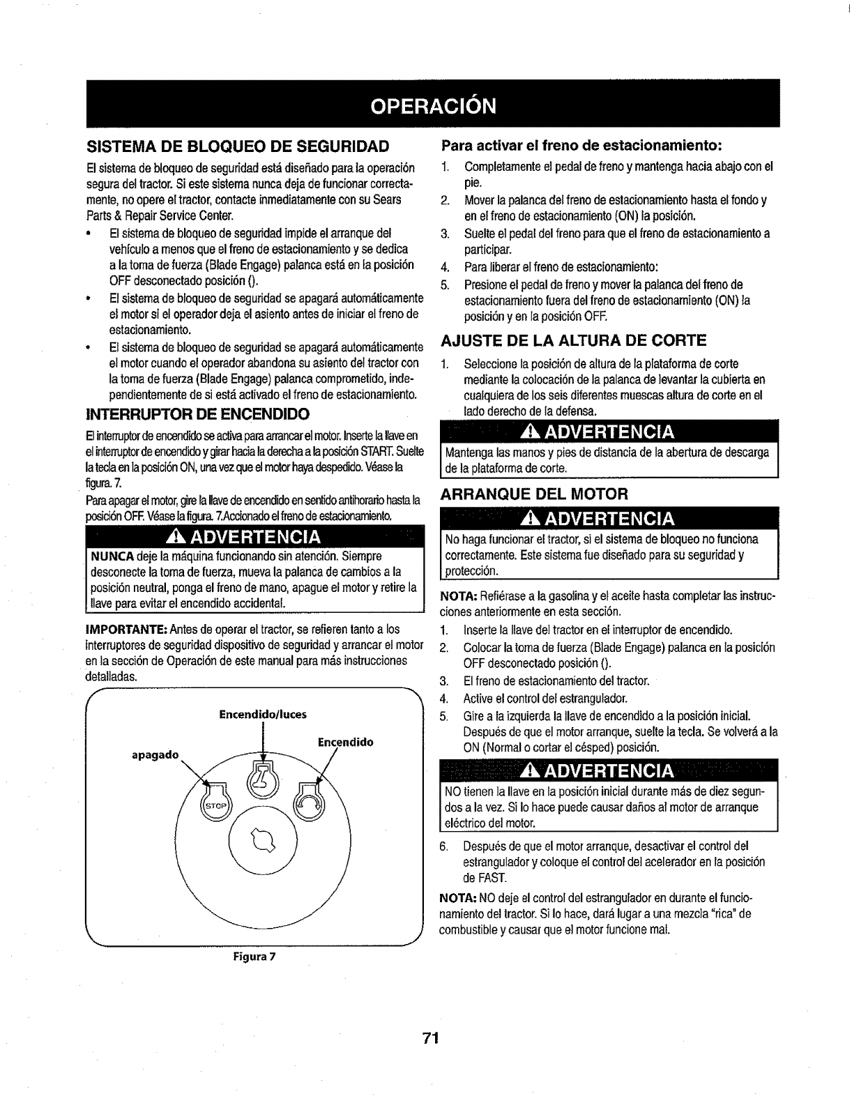
SISTEMA DE BLOQUEO DE SEGURIDAD
Elsistemadebloqueodeseguridadest,.disefiadoparalaoperaci6n
seguradeltractor.Siestesistemanuncadejadefuncionarcorrecta-
mente,noopereeltractor,contacteinmediatamenteconsuSears
Parts& RepairServiceCenter.
• Elsistemadebloqueodeseguridadimpideelarranquedel
vehfculoamenosqueelfrenodeestacionamientoy sededica
a latomadefuerza(BladeEngage)parancaest,,en[aposici6n
OFFdesconectadoposici6n0.
o Elsistemadebfoqueodeseguridadseapagar_autom_ticamente
eJmotorsi eloperadordejaelasientoantesdeiniciarelfrenode
estacionamiento.
°Elsistemadebloqueodeseguridadse apagar_autom_ticamente
elmotorcuandoeloperadorabandonasuasientodeItractorcon
latomadefuerza(BladeEngage)palancacomprometido,inde-
pendienternentedesi est_activadoelfrenodeestacionamiento.
INTERRUPTOR DE ENCENDIDO
ElinternJptordeencendktoseacl_aparaarrancarelmotor.InsertelaIlaveen
elinterruptordeencendJdoygirarhacialaderechaalap_ci6nSTART.Suelte
lateclaenlaposici6nON,unavezqueelmotorh_fadespedido.V_asela
flgura.7
Paraapagarelmotor,girelaIlavedeencendidoensentidoantihorariohastala
posici6nOFEV_aselafigura.7Accionadoelfrenodeestacionarniento.
IMPORTANTE:Antesdeoperareltractor,serefierentantoa los
interruptoresdeseguridaddispositivodeseguridady arrancarelmotor
enlasecci6ndeOperaciOndeestemanualparam,_sinstrucciones
detal]adas.
f
Encendido/luces
Encendido
apagado
Figura 7
Para activar el freno de estacionamiento:
1. Completamenteelpedaldefrenoymantengahaciaabajoconel
pie.
2. Moverlapalancadelfrenodeestacionamientohastaelfondoy
enelfrenodeestacionamiento(ON)laposici6n.
3. Suelteelpedaldelfrenoparaqueelfrenodoestacionamientoa
participar.
4. Paraliberarelfrenodeestacionamiento:
5. Presioneelpedaldefrenoy moverlapalaneadelfrenode
estacionamientofueradelfrenodeestacionamiento(ON)la
posici6nyen laposici6nOFF.
AJUSTE DE LA ALTURA DE CORTE
,Seleccionelaposici6ndealturadelaplataformadocorte
mediantelacolocaci6ndelapalancade]evantarlacubiertaen
cuafquieradelosseisdiferentesmuescasalturadecorteenel
ladoderechodeIadefensa.
Mantengalasmanosy piesdedistanciadelaaberturadedescarga
delaplataformadecorte.
ARRANQUE DEL MOTOR
Nohagafuncionareltractor,si elsisternadebloqueonofunciona
correctamente.Estesisternafue disefiadoparasu seguridady
protecci6n.
NOTA: Refi_rasea la gasolinay el aceite hasta completarlas instruc-
ciones anteriormenteen esta secci6n.
1. Inserte la llave de]tractor en el interruptorde encendido.
2. Colocar la toma de fuerza(BladeEngage) palancaen la posic[6n
OFFdesconeetadoposici6n0-
3. Elfreno de estacionamientodel tractor.
4. Activeel controldel estrangulador.
5. Gire a la izquierdala Ilavede encendidoa la posici6ninicial.
Despu_s deque el motor arranque,suelte la tecla. Se volver_,a la
ON (Normalo cortar e] c_sped)posici6n.
NOtienen la Ilaveen la posici6n inicialdurantem&sde diez segun-
dos a la vez. Si Io hace puedecausar daSosal motor de arranque
el6ctrico del motor.
6. Despu6s deque el motor arranque,desactivarel controldel
estranguladory coloqueel control detacelerador en la posici6n
de FAST.
NOTA: NO deje el controldel estranguFadoren durante el funcio-
namiento del tractor.Si Io hace, dar_ lugara una mezc]a "rica"de
combustible y causar que e] motorfuncione real
71
PARO DEL MOTOR LA CONDUCCION DEL TRACTOR
Sisegolpeaunobjetoextrafio,detengaelmotor,desconecteel
cabledela bujfa(s)ytierracontraelmotor,lnspeccionarcuidadosa-
menteelequipodelosdafios.Reparaci6ndelosdaSosantesde
reiniciary defuncionamiento.
!. Sisededicanalashojas,colocarlatomadefuerza(Blade
Engage)palancaenlaposici6nOFFdesconectadoposici6n0.
2. Girea laizquierdaIaIlavedeencendidoa laposici6nSTOP.
3. Retirela llavedela]lavedeencendido_amevitarelarranqueno
deseado.
Evitecomienzapronto,el excesodevelocidady paradasbruscas.
Nodejeelasientodeltractor,sincolocarlatomadefuerza(Blade
Engage)palancaenlaposici6nOFFdesembragar0 posici6n,
pres]onandoel pedaldefrenoy aecionadoelfrenodeestaciona-
miento.Sinopuedesalirdeltractorsinvigilancia,tambi_na suvez
laIlavedeencendidoapagadoy quitarlaIlave.
Pisarel embrague-pedaldefreno para liberarel freno de estaciona-
mientoy dejar que el pedal.
Moverla palanca del acelerador en e! FAST(conejo) la posici6n.
Coloque la palancade cambiostanto enla posici6n inversao
FORWARD.
IMPORTANTE:NO utilizarla palancadecambios para cambiarla
direcci6n de la marcba cuandoel tractor est_en movimiento.Siernpre
utilice elfreno depedal de embragueparaque el tractor a unaparada
completa antes de pasar.
Suelte el freno de estacionamientopresionandoetembrague-pedalde
freno y el posicionamiento dela palanca de control develocidad en ta
posici6n deseada.
En primerlugar IMPORTANTE:-tiempo,los operadores debenutilizar
posicionesde velocidad de 1 o 2. Convi_rtetetotalrnentefamiliarizado
con el funcionamientodel tractor y loscontroles antes de operar el
tractor en los puestos de mayorvelocidad.
Embrague-pedaldefreno lenlamente paracolocarla un]daden
movimiento.
El tractor de c_sped es Ilevadoa una paradapresionandoel
embrague-pedalde freno.
NOTA:Cuandoopere ]a unidadinicial, habr_,pocadiferencia entre las
dos ve]ocidadesm_s altashasta despu6s delos cinturonesse han
sentado en laspoleasduranteel periodode rodaje.
IMPORTANTE:At parar eltractor, por cualquiermotivo, rnientrasque
en unasupefficie de hierba, siempre:
1. Coloquela palancade cambios en puntomuerto,
2. Aplique elfreno de estacionamiento,
3. Apague el motory quitarla ttave.Si Iohace, reducir,_al mfnimola
posibilidadde que su c6sped se dore'"'por el escapecaliente del
motorde su tractor.
72

Siseestancala unidadconelcontroldevelocidadenaltavelocidad,
osila unidadnofuncionar_conlapalancadecontroldevelooidaden
condicionesdebajavelocidad,sigaestospasos:
1. Lapalancadecarnbiosenpuntornuerto.
2. Reinicieelmotor.
3. Coloquela palancadecontroldevelocidadenlaposici6nrn_.s
altavelocidad.
4. Embrague-pedaldefrenocornpletarnente.
5. Pisarelernbrague-pedafdefreno.
6. Coloquelapalancadecontroldevelocidadenlaposfci6n
deseada.
7. Coloquelapatancadecambiosencualquieradeavanceo retro-
ceso,y seguirlosprocedimientosnorrnalesdefuncionarniento.
CONDUCClON EN LAS LADERAS
Refierenalanchode]a pendienteen]aseguridaddelaspr_.cticasde
operaci6nirnportantesecci6nde]manualparaayudaradeterrninar
zonasdeladeradondepuedeoperareltractorcontotalseguridad.
Nocorteelc_spedenpendientesconunainclinaci6ndern,_sdeI5
grados(unaumentodeaproxirnadamente2-I/2 piescada10pies).
Eltractorpuedevocary causarlesionesgraves.
•Corte el c_spedy las pendientes,nuncatransversal.
• Tenga extrema precauci6nal cambiar dedirecci6n en las
pendientes.
•Watch paralos agujeros,grietas,baches, piedrasu otros objetos
ocultos. Terrenoirregularpuede revertirla m_.quina.Elc_sped
alto puedeocultarobst_.culos.
•Evitegirarcuando se circula por una pendiente.Si una vez, debe
hacerse, a su vez por la pendiente. El regresode una pendiente
aumenta la posibilidadde unroll over.
• Evitedetenerse cuandose conduce por una pendiente.Si es
necesario detener mientrasse conduce poruna pendiente,
puesta en rnarchasin problernasy concuidado para reducir !a
posibilidad de voltear el tractor hacia atr_.s.
INVOLUCRAR A LOS BLADES
Participaci6ndelatornadefuerza(BladeEngage)lastransferenciasde
energfaafaplataforrnadecorteodeottotipo(disponibleporseparado)
losarchivosadjuntos.ParaparUcipardelashojas,haga1osiguiente:
1. Moverlapalancadecontroldelaceleradorala r_pida(conejo)la
posici6n.
2. Sujetelatomadefuerza(BladeEngage)y girarlapalancade
todoelcarninoaseguiralos novios(ON)laposici6n.
3. MantengalapalancadelaceleradorenelFAST(conejo)la
posici6nparaelusorn,'_seficientedelaplataforrnadecorteode
otrotipo(disponiblepotseparado)losarchivosadjuntos.
IMPORTANTE-"EnelreversoPrecauci6nmodoqueelmotorse
apagar,_autom_ticarnentesiiatornadefuerzaest_comprornetidacon
lapalancadecontroldevelocidadenlaposiciSninversaparaviajar
con]a ltavedeencendidoenlaposici6nnormaldesiega.
USO DE LA CUBIERTA DE LEVANTE LA
PALANOA DE
Paraetevarlaplataforrnadecorte,moverla palancadeelevaci6nde
cubiertaa laizquierda,luegosecolocaen]aranurarn_sadecuada
parasuaplicaci6n.ConsuEteAjustelaalturadecorteanteriorrnenteen
estasecci6n.
73¸
CORTAR
Paraayudara evitarelcontactoconlacuchillaounalesionen
elobjetolanzado,Mantengaalosespectadores,losayudantes,
losnifiosy lasmascotasporIomenos75piesdedistanciadela
m_.quinamientrasest_enfuncionamiento.Paradadelam_iquina,si
alguienentraenel,_rea.
LasiguienteinformaciOnser_etil cuandose utilizala pfataformade
cortecon su tractor:
I haciala_m s, evitematerial
I qu_strucciOn que puede
causar alta materiala rebotar haciael operador.
• No corteel c_speda la velocidaddeterreno elevado,especial-
mentesi se ha instalado un kitde mantillo o colector decOsped.
• Paraobtenerlos mejores resultadosse recomiendaque las
dosprimerasvueltas se cortar_,con la aprobaciOnde la gestiOn
arrojadohacia el centro. Traslas dos primerasvueltas, invertire!
sentido de lanzarla descarga haciael exteflorde la balanzade
corte. Estole dareruna mejor aparienciaal cOsped.
, Nocorte elcOspeddemasiadocorto. Pastocortoinvita erecimiento
de matashierbasy losamarilIosconrapidezen eltiemposeco.
, Cortarel c_spedsiempre se debe hacercon el motora todo gas.
• Bajolas condiciones m_s pesadas,puedeset necesariovolver
sobre la zona del corte pot segundavez paraobtenerun corte
limpio.
• NOintentecortarespesamalezay malashierbasyel pastomuyalto.
Sutractorest,.disefiadoparacortarelc_sped,uncepil]onoest_claro.
° Mantengalas cuchillas afiladas y sustituir las cuchillas en caso
de desgaste. ConsulteHojas de corte en el servicioy la secciOn
Mantenimientode este manualde instrucciones deafilar tahoja
adecuada.
FAROS
•LasI&mparasest_nONcuandoelmotorde!tractorse est,.
ejeeutando.
• Laslucesseapagacuandolatlavedecontactose muevea la
posiciOnSTOP.
74

LISTA DE MANTENIMIENTO
Antesderealizarcualquiertipoclefmantenimientotservicio,suelte
todoslosmandosy pareelmotor.Esperehastaquetodaslaspartes
demovimientohayanvenidoa unaparadacompleta.Desconecteel
alambredebujfay b_selocontraelmotorparaprevenirelcomienzo
involuntario.SiempreIlevepuestoscristalesinastillablesdurantela
operaci6no realizandocualquierajusteoreparaciones.
Sigalalistademantenimientodadaabajo.Estacartadescribepautas
deservicios61o.UselacolumnadeTroncodeServicioparaguardarla
pistadetareasdemantenimientocompletadas.
Localizarel m_scercanoChamuscaelCentrodeServicioopro-
gramarelservicio,simplementeponerseencontactoChamusca
en 1-800-4-MY-HOME®.
Antes decada uso
Losprimeroscincohoras
Cada 10horas
Carla 25 horas
Carla50 horas
Anualmente
Antes deAlmacenaje
1. Niveldel aceitede motor
2. Silenciadorzona y loscontro]es
3. Dedode la manode guardia
1. El aceitedel motor
1. El cap6/Ios respiraderos
2. Losbornes de la baterfa
3. Loshusitlosy fa m6nsulaintermedia de la
plataforma
1. Eldepurador del filtro de aire*
2. Filtrode aire*
3. Losbrazosde mando intermedios,ejes del
pivotey ejes
4. Losrodamientosde las ruedas delanteras
5. Las ruedas delanterasde la plataforma
1. Elaceite del motor/el fiftro de aceite
2. Silenciador
t. Filtrode aire
2. Eldepuradordel filtrode aire
3. Bujfa
4. Sistemade refrigeraci6npor aire*
5. Filtrode combustible
6. DirectivoEngranajes
7. Ruedastraseras
t. El cap6/Ios respiraderos
2. Losbomes de la bateria
3. Losbrazos de mando intermedios, ejes del
pivotey ejes
4. Losrodamientosde las ruedasdelanteras
5. Lasruedas delanterasde ta plataforma
6. Loshusillos y la m6nsulaintermedia de ta
plataforma
7. Lospuntosde pivotedel pedal
* Realice elservicio m_.sfrecuentementecuandohaya mucho polv01
t. Comprobar
2. Limpie
3. Limpie
1. Cambie
1. Limpie
2. Limpie
3. Lubrique
t. Limpie
2. Limpie
3. Lubrique
4. Lubrique
5. Lubdque
I. Cambie/reemplace
2. Comprobar
1. Reemplace
2. Reemplace
3. Reemplace
4. Limpie
5. Reemplace
6. Limpie
7. Quitela grasay losejes
1. Limpie
2. Limpie
13. Lubrique
4. Lubrique
5. Lubrique
6. Lubrique
7. Lubrique
i !'V;I .ivj :I .i i :I I [o]I; :'V;I .III :l :i i i I [i_ l-
Antes de realizartareasde mantenimientoo reparaciones, l Si e] motorse ha puestoenfuncionamientorecientemente,el motor,
Idesconectela potenciade arranque(PTO), coloque elfreno de i ]silenciador y ]as superficiesmet_]icascircundantesestar,_ncalientes
]mano, apagueel motory retirela llave, para evitarel encendido [y puedencausar quemadurasa la piel.Tenga precauci6npara evitar
]accidentaldel motor, iquemaduras.
75
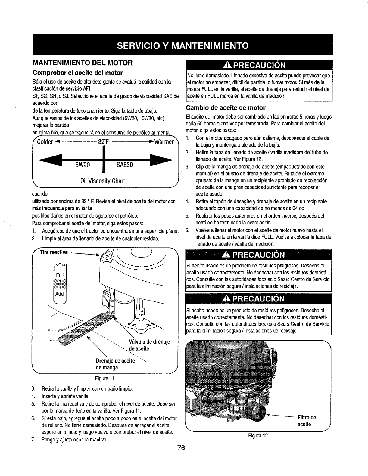
MANTENIMIIENTO DEL MOTOR
Comprobar el aceite del motor
$61oel usode aceite dealta detergentese evalu6lacalidadconia
clasificaci6ndeservicio API
SF,SG, SH, o S.J.Seleccioneel aceite de grado de vlscosidadSAE de
acuerdocon
dela temperaturadefuncionamiento. Siga la tablade abajo.
Aunque ratiosde los aceitesde viscosidad(5W20, IOW30,etc)
mejorarla partida
enclirnafrfo, quesetraducir&en el consumode 10etr61eoaumenta
fColder _ 32°F =--Warrne_"/
I
',,. JOilViscosity Chart ............... j
cuando
utilizado por encimade 32 ° E Revise el nivel de aceitedel motorcon
m_.sfrecuencia paraevitar la
posiblesdaSosen el motorde agotarse el petr61eo.
Paracomprobarel aceite del motor,siga estospasos:
t. Aseg_resede que el tractor se encuentra en una superficie plan&
2. Lirnpiee! ,_reade llenado de aceite de cualquierresiduo.
V_tvulade drenaje
deaceite
Drenajedeaceite
demanga
Figura11
3. Retirelavarillay limpiarcon unpatiolirnpio.
4. Insertey aprietevarilla.
5. Retirelatirareactivay decomprobarelniveldeaceite.Debeser
porlamarcadeIlenoenlavarilla.VerFigura11.
6. Siestabajo,agregueelaceitepocoa pocoenelaceitedelmotor
derelleno.NoIlenedemasiado.Despu_sdeagregarelaceite,
espereunminutoy luegovuelvaacomprobarel nivetdeaceite.
7. Pongay ajustecontirareactiva.
76
lNoIlenedemasiado.Uenadoexcesivodeaceitepuedeprovocarque
elmotornoernpezar,dificildeparlida,ofumarmotor.Sim_sdela
marcaFULLenlavarilla,elaceitededrenajeparareducirel nivelde
aceiteenFULLmarcaenlavarillademedici6n.
Cambio de aceite de motor
Elaceitedelmotordebesetcambiadoenlasprimeras5 horasy luego
cada50horasounavezporternporada.Paracarnbiarelaceitedel
motor,sigaestospasos:
1. Conelmotorapagadoperoa_ncaliente,desconecteelcablede
la bujiay mant_ngaloalejadodelabujia.
2. Retirelatapadellenadodeaceitetvariltamedidoradettubode
]lenadodeaceite.VerFigura12.
3. Clipdelamangadedrenajedeaceile(empaquetadoconeste
manual)enelpuertodedrenajedeaceite.Rutadeel extremo
opuestodelamangaenunrecipienteapropiadode recolecciOn
deaceiteconunagrancapacidadsuficientepararecogerel
aceiteusado.
4. Retireeltap6ndedesag0ey drenajedeaceiteenunrecipiente
adecuadoconunacapacidaddenomenosde64oz
5. Realizarlospasosanterioresenelordeninverso,despu6sdel
petr61eohaterminadolaevacuaci6n.
6. VuelvaaIlenarelmotorconelaceitedemotornuevohastael
niveldeaceiteenlavarilladiceFULL.Vuetvaa colocarlatapade
Ilenadodeaceite/varillademedici6n.
El acelte usado es unproduclo de residuespeligrosos.Deseche el
aceite usadocorrectarnente,No desechar con los residuosdorn6sli-
cos. Consulte con las autoridadeslocalesoSearsCentrode Servicio
)ara la eliminaciSnseguraIinstalacionesde reciclaje.
Elaceite usado es un productode residuospeligrosos.Deseche el
aceite usadocorrectamente.No desechar con los residuosdom_sti-
cos, Consultecon las autoridadeslocaleso SearsCentrode Servicio
parala elirninaci6nsegura/instalacionesde reciclaje.
Figura 12
Filtrode
aceite J
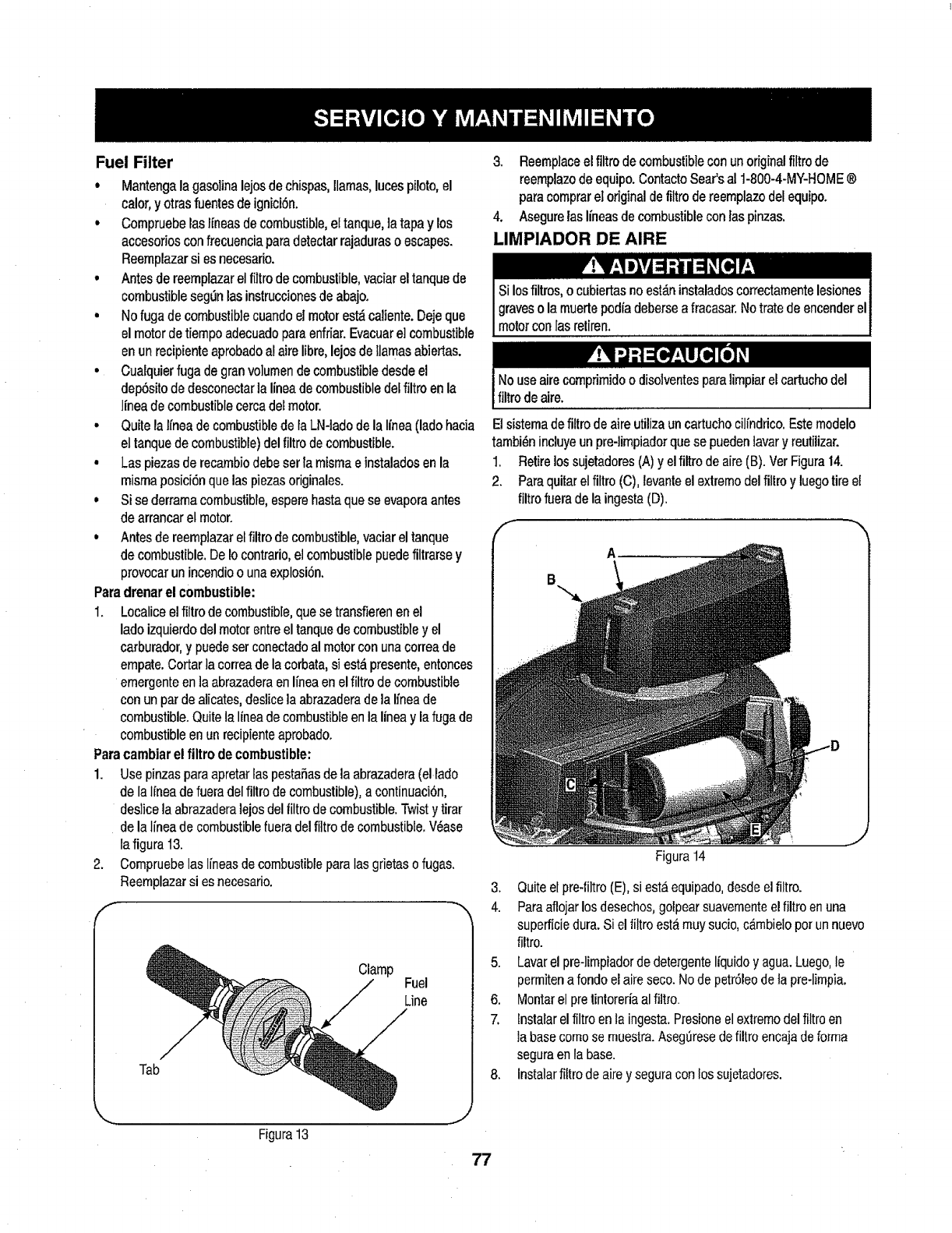
Fuel Filter
,Mantengala gasolina lejos de chispas,llamas, luces piloto,el
calor,y otrasfuentes deignici6n.
, Compruebelaslfneas de combustible,el tanque, ]atapa y los
accesorios confrecuenciaparadetectarrajaduraso escapes.
Reemplazarsi es necesado.
• Antes de reemplazarel filtro de combustible, vaciar el tanque de
combustible seg_n lasinstruccionesde abajo.
• No fuga de combustible cuando el motorest_ caliente. Deje que
el motor detiempo adecuadopara enfriar. Evacuare] combustible
enun recipienteaprobadoal aim libre, lejos de llamasabiertas.
• Cuaiquier fuga degran volumende combustibledesde el
dep6sito de desconectar la lineade combustible delfiltro enla
linea de combustible cercadel motor.
• Quite la lfnea decombustible de laLN-lado de la Ifnea(lado hacia
el tanque de combustible)del filtro de combustible.
• Las piezas de recambiodebe ser {amisma e instaladosen la
misma posici6nque las piezasoriginales.
• Si se derramacombustible, espere hasta que se evapora antes
de arrancarel motor.
• Antes de reemp]azarel filtro de combustible,vaciar el tanque
de combustible. De Iocontrario,el combustible puedefiltrarse y
provocar un incendioo una explosi6n.
Para drenar el combustible:
I. Localice el filtro de combustible, quese transfieren enel
lado izquierdo del motor entre el tanque de combustible y el
carburador,y puede ser conectadoal motorcon una correa de
empate.Cortar la correa de la corbata, si est_ presente, entonces
ernergenteen ]a abrazaderaenIfnea en elfiltro decombustible
con un par de alicates,deslice]a abrazaderade la Ifneade
combustible.Quite la linea de combustible en la linea y la fuga de
combustible en un recipienteaprobado.
Para cambiar el filtro de combustible:
1. Use pinzas paraapretar las pestaSasde la abrazadera (el lado
de la Ifnea de fueradel filtro de combustible),a continuaci6n,
deslicela abrazaderalejos del filtro de combustible. Twist ytirar
de la linea de combustiblefuera del filtro de combustible.V_ase
la figura I3.
2. Compruebelas lineas de combustible para las grietaso fugas.
Reemplazarsi es necesario.
f
Clamp
Fuel
Line
Tab
Figura 13
3, Reemplaceelfiltrodecombustibleconunoriginalfiltrode
reemnplazodeequipo.ContactoSear'sal 1-800-4-MY-HOME®
paracomprareloriginaldefiltrodereemplazodelequipo.
4. Asegurelas lineasdecombustibleconlaspinzas.
LIMPIADOR DE AIRE
Si losfiltros, o cubiertasno est_.ninstaladoscorrectamentelesiones
graveso la muertepodia debersea fracasar.Notrate de encender el
motorconlas mtiren.
t Nouseairecornprimidoodisolventesparalimnpiarelcartuchodel
filtrodeaire.
Elsistema defiltro de aire utiliza un cartuchocilindrico. Estemodelo
tambi_n incluyeun pre-limpiadorquese pueden lavary reutilizar.
1. Retire lossujetadores(A) y el filtro de aire (B). Ver Figura 14.
2. Paraquitar et filtro (C), levanteel extremodel filtro y luego tire el
filtro fuerade la ingesta(D).
Figura 14
3. Quiteel pm-tiltro (E), si est.4equipado,desde elfiltro.
4. Paraaflojar los desechos,golpearsuavemnenteel filtro en una
supefficie dura. Si el tiltro esta muysucio, c&mbielo por un nuevo
filtro.
5. Lavarel pre-lirnpiadorde detergenteliquido y agua.Luego,le
permitena fondoel aim seco. No de petr61eode ta pre-limpia.
6. Montarel pretintoreria al fittro.
7. lnstalar el filtro enla ingesta.Presione el extremodel filtroen
la basecome se muestra.AseglJresede filtro encaja de forrna
segura en la base.
8. Instalarfiltro de aim y segura con los sujetadores.
77
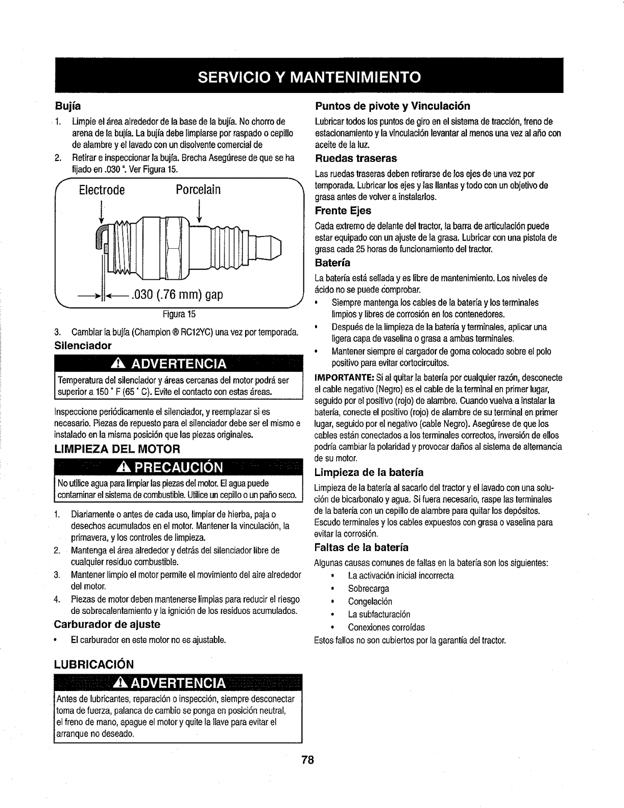
Bujia
1. Limpieel _.reaalrededorde la base de la bujfa. No chorrode
arena de la buifa. La bujfadebe limpiarsepot raspadoo cepil!o
de alambrey el lavadocon undisolventecomercialde
2. Retirar e inspeccionar la bujfa. BrechaAseg_resede que se ha
fijado en .030 ". Ver Figura 15.
Electrode Porcelain
.030 (.76 mm) gap
Figura 15
3. Cambiarlabujfa(Champion®RC12YC)unavezportemporada.
Silenciador
Inspeccione peri6dicamenteel silenciador,y reemplazar si es
necesario. Piezasde repuesto para et silenciadordebe ser el mismo e
instaladoen la misma posici6n que las piezasoriginales.
UMPIEZA DEL MOTOR
NoutiliceaguaparaIimpiarlaspiezasdelmotor.Elaguapuede
contaminarelsistemadecombustible.Utiliceuncepilloounpasoseco.
1. Diariarnente o antes de cada uso,limpiar de hierba, pajao
desechos acumuladosen el motor. Mantenerla vinculaci6n,Ia
primavera,y los controles de limpieza.
2. Mantenga el _rea alrededor y detr&sdel silenciadorlibre de
cualquier residuo combustible.
3. Mantener limpio el motor permite el movimientodel aire alrededor
del motor.
4. Piezas de motor debenmantenerseIimpiaspara reducirel riesgo
de sobrecalentamientoy la ignici6nde los residuosacumutados.
Carburador de ajuste
•El carburadoren este motorno es ajustable.
Puntos de pivote y Vinculaci6n
Lubricartodoslospuntosdegiroenelsistemadetracci6n,frenode
estacionamientoylavinculaci6nlevantaralmenosunavezalaSocon
aceitedetaluz.
Ruedas traseras
Las ruedastraserasdeben retirarsede los ejes de una vez por
temporada.Lubricarlos ejes y las Ilantasy todo conun objetivode
grasaantes de volvera instalarlos.
Frente Ejes
Cada extremode delantedel tractor,la barrade articulaci6n puede
estarequipado conun ajuste de la grasa. Lubricar conuna pistolade
grasacada 25 horasde funcionamientodel tractor.
Bateri'a
Labaterfaest,_selladayes Iibre de mantenimiento.Los nivelesde
_cido nose puede comprobar.
• Siempre mantengalos cables de la baterfay los terminales
limpiosy libresde corrosi6nen los contenedores.
,Despu_s de la limpiezade la baterfay terrninales,aplicar una
ligera capa de vaselinao grasaa arnbasterminales.
•Mantener siempre elcargador de goma colocado sobreel polo
positivoparaevitar cortocircuitos.
IMPORTANTE: Sial quitarla baterfaporcualquierraz6n,desconecte
el cablenegativo (Negro)es el cable de la terminal enprimer lugar,
seguido por el positivo(rojo) dealambre. Cuandovuelva a instalarla
bater/a,conecte el positivo(rojo) de alambrede su terminal en primer
lugar,seguido pot el negativo(cable Negro). Aseg_resede que los
cables est_.nconectadosa los terminalescorrectos,inversi6nde ellos
podrfacambiar fa polaridad y provocardaSosal sistemade alternancia
de su motor.
Lirnpieza de la baterfa
Limpiezade la baterfa al sacarlo deltractor y el lavadocon una solu-
ci6n de bicarbonato y agua.Si fuera necesario, raspelas terminales
de la baterfa conun cepillo de alambrepara quitarlos dep6sitos.
Escudo terminalesy loscables expuestos con grasa o vaselinapara
evitar la corrosi6n.
Faltas de la bateria
Algunascausascomunes de fallas en la bateria son lossiguientes:
•Laactivaci6n inicialincorrecta
•Sobrecarga
• Congelaci6n
•Lasubfacturaci6n
•Conexionescorroidas
Estosfallos no son cubiertos por la garantia del tractor.
LUBRICACI()N
!'II,.1 ilvl _ii / ;I ![!l IL'
tAntes de lubricantes, reparaci6no inspecci6n,siempredesconectar I
jtoma de fuerza, palanca decambiose pongaen posici6n neutral, [
iel freno de mano, apague el motory quite fa ]laveparaevitar el [
larranqueno deseado. [
78
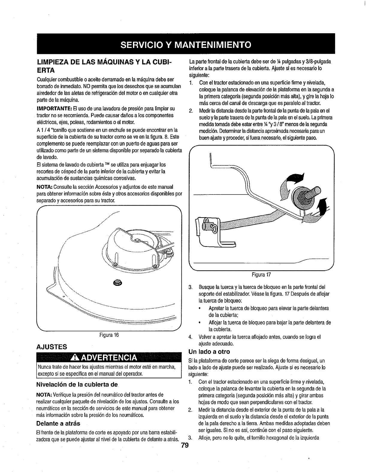
LIMPIEZA DE LAS MAQUINAS Y LA CUBI-
ERTA
Cualquiercombustible o aceite derramado en la m_,quinadebe ser
borrado de inmediato. NOpermita que los desechosque se acumulan
alrededorde las aletas de refrigeraci6ndel motor o en cuafquierotra
parte de la m_.quina.
IMPORTANTE: El usode una lavadorade presi6n paralimpiar su
tractor no se recomienda. Puedecausar da5os a loscomponentes
el_ctdcos,ejes, poleas, rodamientoso el motor.
A 1t4 "tornillo que sostiene en un enchufese puedeenconlrar en la
superficiede la cubierta de su tractor comose ve en lafigura. 8.Este
complementose puede reemplazarconun puerto de aguasparaser
utilizadocomo partede un sistema disponiblepor separadola cubierta
de lavado.
El sistemade lavado de cubierta TMse utilizapara enjuagarlos
recorles dec6sped de la parte inferiorde la cubierta y evitar la
acumulaci6nde sustancias quimicas corrosivas.
NOTA: Consultela secci6nAccesoriosy adjuntos de este manual
paraobtenerinformaci6n sobre_ste y otros accesoriosdisponibles por
separadoy accesorios parasu tractor.
"_\k_"_\ . "_-,_.,
\ .J
Figura 16
AJUSTES
Nivelaci6n de la cubierta de.
NOTA: Verifiquela presiOndel neum_.ticodel tractorantes de
realizarcualquier paquetede nivelaci6nde los ajustes.Consulte a los
neum_ticosen la secci6n de serviciosde este manualpara obtener
m_isinformaci6nsobrela presi6nde losneum_ticos.
Delante a atrds
Elfrente de la plataformade corte es apoyado por unabarra estabili-
zadoraque se puedeajustar al nivel de la cubiertade delante a atr_,s.
Lapartefrontaldelacubiertadebeserde¼pulgadasy 3t8-pulgada
inferioratapartetraserade[acubierta.Ajustesi es necesarioIo
siguiente:
1. Coneltractorestacionadoenunasuperticiefirmey nivelada,
coloquelapalancadeelevaci6ndelaplataformaenlasegundaa
la primeracategoria(segundaposici6nm_.salta),y girela hojaIo
m_scercadelcanaldedescargaqueesparaleloaltractor.
2. Medirladistanciadesdelapartefrontaldelapuntadelapafaenel
sueloylapartetraseradelapuntadelapalaenelsueIo.Laprimera
medidatomadadebeestarentre¼"y3/8"menosdelasegunda
medici6n.Determinarladislanciaaproximadanecesariaparaun
buenajustey proceder,sifueranecesario,elsiguientepaso.
f
f_
,.... j
Figura17
3.
79
3. Busque la tuercay latuercade bloqueo enla partefrontal del
soporte del estabilizador.V_ase lafigura. 17 Despu_sde aflojar
la tuerca de bloqueo:
• Apretar Iatuerca de bloqueopara elevar la parte delantera
de la cubierta;
•NIojar la tuerca debloqueo para bajarla partedelanterade
la cubierta.
4. Volver a apretar la tuercaaflojadoantes, cuando se logra el
ajuste adecuado.
Un lado aotro
Si la plataforma decorte parece serla siega de forma desiguat,un
lado a lado de ajuste puedeset realizado.Ajuste si es necesario Io
siguiente:
1. Con el tractor estacionado en una superficie Iirme y nivelada,
coloquela palanca de levantar lacubierta en la segunda de la
primera categoria(segundaposici6nm_s alta) y girarambas
hojas de modo que seanperpendicularescon e] tractor.
2. Medir ladistancia desdeel exteriorde la punta de la palaa la
izquierda enel sueloy la distanciadesde el exterior de la punta
de la paladerechoa la tierra.Ambas medidas adoptadasdeben
ser iguales.Si no es asi, contin0e coneI pasosiguiente.
Alloje,pero no Io quite, eltornillo hexagonalde ]aizquierda
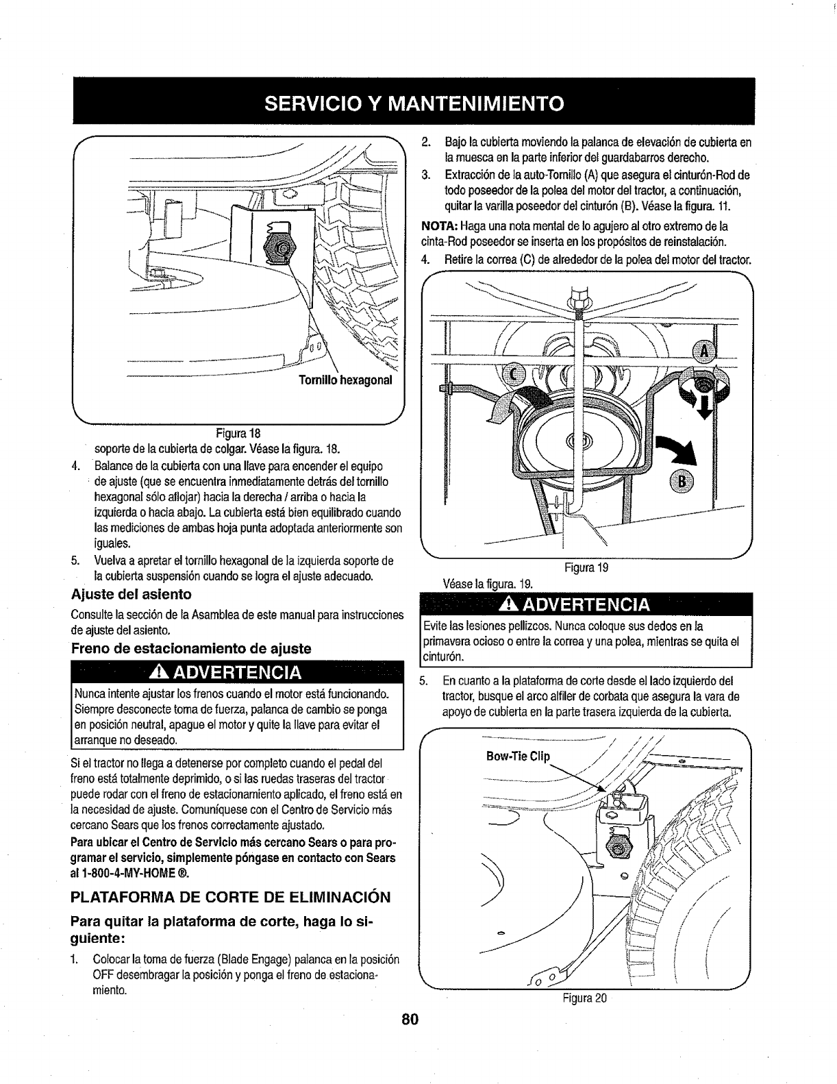
Figura18
soportedelacubiertadecolgar.V_aselafigura,t8.
4. BalancedelacubiertaconunaIlaveparaencenderelequipo
deajuste(queseencuentrainrnediatamentedetr_sdeltornillo
hexagonals6Ioaflojar)hacialaderechaiarriba o hacia la
izquierdao hacia abajo. La cubierta est_ bien equilibradocuando
lasmediciones de arnbashoja puntaadoptada anteriormenteson
iguales.
5. Vuelva aapretar eltomillo hexagonalde la izquierda soporte de
la cubiertasuspensi6n cuandose Iograel ajusteadecuado.
Ajuste del asiento
Consulte la secci6nde laAsamblea de este manualpara instrucciones
de ajuste del asiento.
Freno de estacionamiento de ajuste
Si el tractor no Ilegaa detenersepor completocuando el pedal del
freno est_ totalmente deprirnido,o si las ruedas traseras del tractor
puede rodar con elfreno de estacionamientoapllcado,el freno est_ en
ta necesidad deajuste. Cornunfquesecon el Centrode Servicio m_s
cercano Searsque losfrenos c0rrectamenteajustado.
Para ubicar el Centro de Servicio mdscercano Sears o para pro-
gramarel servicio,simplemente p6ngaseen contacto con Sears
al 1-800-4-MY-HOME®.
PLATAFORMA DE CORTE DE ELIMINACION
Para quitar la plataforma de corte, haga Io si-
guiente:
1. Colocarlatornadefuerza(BladeEngage)pa]ancaenlaposici6n
OFFdesembragarlaposici6ny pongaelfrenodeestaciona-
rniento.
80
2. Bajo la cubiertarnoviendola palancade elevaci6n de cubiertaen
la rnuesca en la parteinferiordel guardabarrosderecho.
3. Extracci6n de la auto-Tomillo(A) que asegurael cintur6n-Rod de
todo poseedorde la polea del motordel tractor, a continuaci6n,
quitar la varilla poseedor del cintur6n (B). V_ase lafigura. 1t.
NOI"A; Hagauna nota mentalde Ioagujeroal otto extrernode la
cinta-Rodposeedor se insertaen los prop6sitosde reinstalaci6n.
4. Retire la correa (C) de alrededor de la polea del motor del tractor.
f ",
f
V_ase lafigura. 19.
Figura19
J
Evitelas lesiones pellizcos.Nuncacoloquesus dedos enla
primaveraocioso o entre la correa y una polea, rnienlras se quita el
cintur6n.
,Encuanto a la plataformade corle desdeel ladoizquierdodel
tractor, busqueel arco alfiler decorbata que asegura la varade
apoyode cubierta en la partetraseraizquierdade la cubierta.
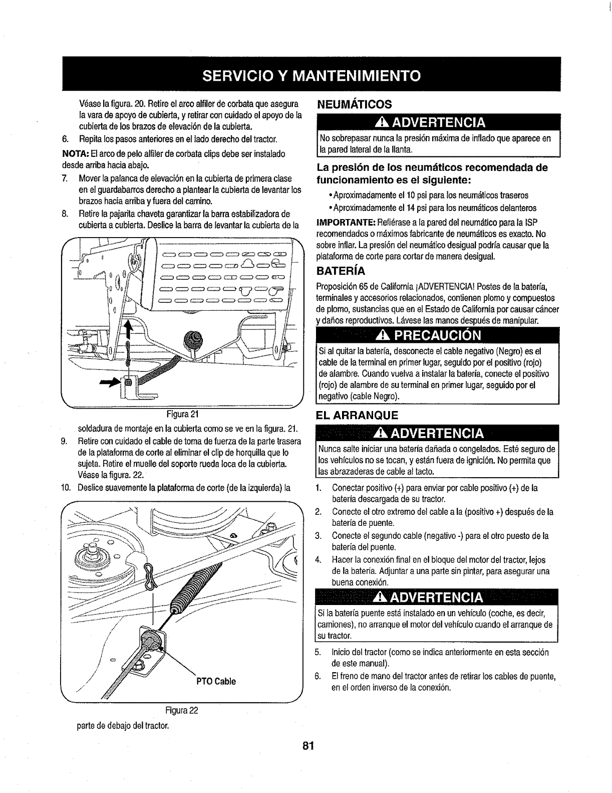
V_aselafigura.20.Retireelarcoalfilerdecorbataqueasegura
tavaradeapoyodecubierta,y retirarconcuidadoelapoyodela
cubiertadelosbrazosdeelevaci6ndelacubierta.
6. Repitalospasosanterioresenelladoderechodeltractor.
NOTA:Elarcodepeloalfilerdecorbataclipsdebeserinstalado
desdearribahaciaabajo.
7. MoverIapalancadeelevaci6nenlacubiertadeprimeraclase
enelguardabarrosderechoaplantearlacubiertadelevantarlos
brazoshaciaerribay fueradelcamino.
8. Retirelapajaritachavetagarantizarlabarraestabilizadorade
cubiertaacubierta.Deslicelabarradelevantarlacubiertadela
f
9,
.J
Figura 21
soldadura dernontaje en la cubierla como se ve enla figura. 21.
Retire concuidado el cable detoma de fuerza de la partetresera
de la plataformede corte al eliminar elclip de horquilla que Io
sujeta. Retire el muelledel soporte rueda Iocade la cubierta.
V_ase ]afigura. 22.
Deslice suavernentela plataforrnade corte (de la izquierda)ta
PTOCable
Figura22
partededebajodeltractor.
NEUMATICOS
Nosobrepasarnuncalapresi6nm_ximadeinfladoqueapareceen
laparedlateraldelaIlanta.
La presi6n de los neumdticos recomendada de
funcionamiento es el siguiente:
•Aproximadamenteel 10psi paralos neum_ticostraseros
•Aproximadarnenteel 14psipara los neurn__ticosdelanteros
IMPORTANTE: Refi_rasea la pareddel neum_.ticoparala ISP
recomendadoso m_ximosfabricante deneum_.ticoses exacto.No
sobre inflar. La presi6n del neum,'_ticodesigual podrfacausar que la
plataforrnade cortepare cortar de maneradesigual.
BATERfA
Proposici6n65 de California iADVERTENCIA!Postesde Ia baterfa,
terminalesy accesoriosrelacionados,contienen plomo y compuestos
de plomo,sustancias queen el Estadode California por causerc_.ncer
y daSos reproductivos.L_veselas rnanosdespu_s de manipular.
Sial quitar la bateria, desconecteel cablenegativo (Negro)es el
cablede la terminal en primer lugar,seguido porel positivo (rojo)
de alambre.Cuandovuelvaa instalarla baterfe,conecte el positivo
(rojo) de alambre de su terminal en primer lugar,seguido por el
negativo(cableNegro).
EL ARRANQUE
lasabrazaderasdecableaftacto.
1. Conectar positivo{+) paraenviar por cable positivo (+)de la
bateria descargadade su tractor.
2. Conecteel otro extremodel cable ale (positivo +) despu_sde la
beterie de puente.
3. Conecteel segundo cable (negativo-) parael otto puestode le
bateria del puente.
4. Hacer la conexionfinal enel bloque del motordel tractor, lejos
de la baterfa.Adjunter euna parle sin pintar,para asegurar una
buenaconexi6n.
camiones),no arranqueel motor del vehfculocuandoel arranquede
su tractor.
5. Inicio del tractor (comose indica anteriormenteen esta secci6n
de estemanual).
6. Elfreno de mano del tractor antes de retirarlos cables de puente,
en elorden inversode la conexion.
81
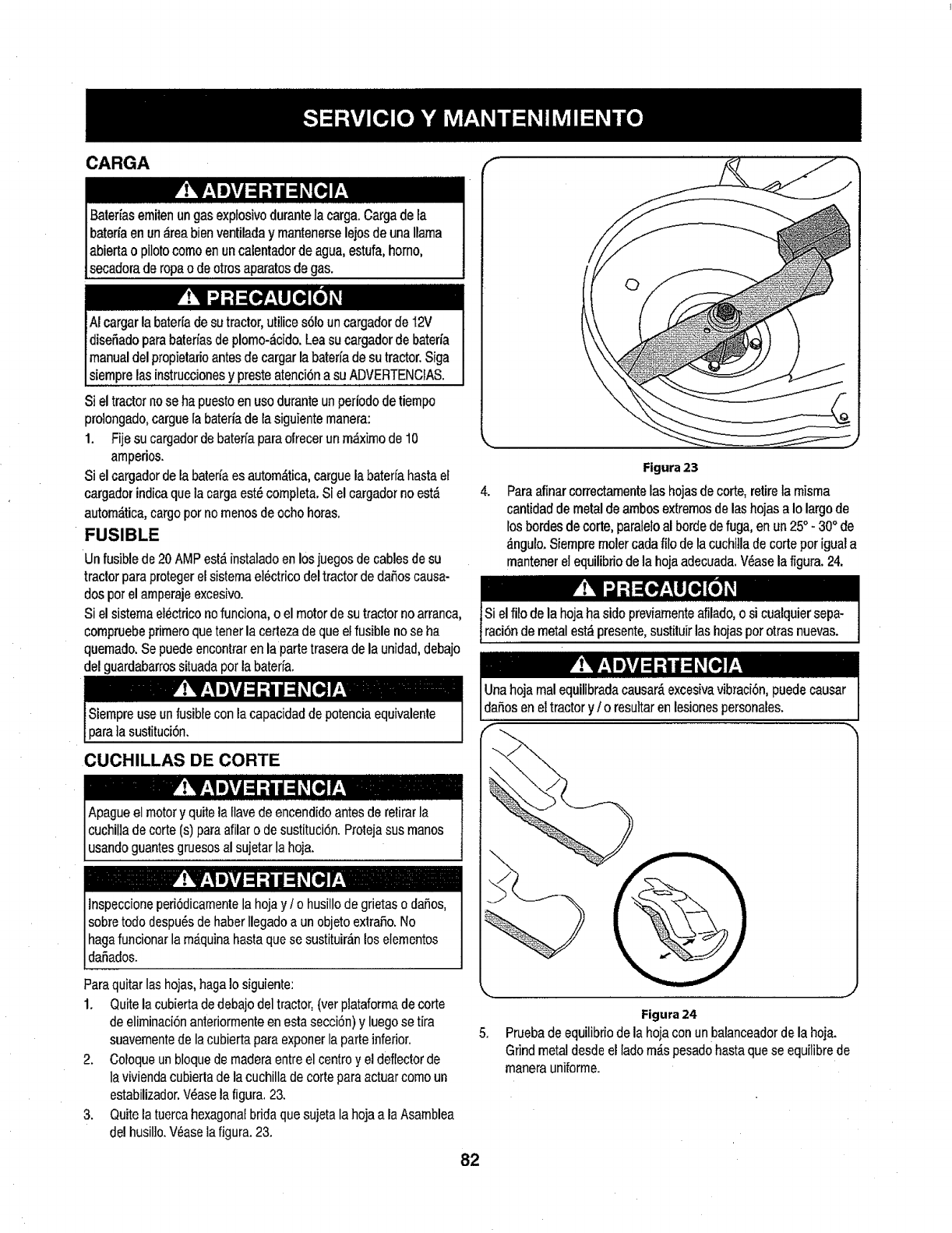
CARGA
Baterias emitenun gas exptosivo durantela carga.Carga de ta
batefia en un _,reabJenventilada y mantenerselejos de una llama
abierta o pilotoeomoen uncalentador de agua,estufa, homo,
secadora,de ropao de otros aparatosde gas.
Si el tractor no se ha puestoen usodurante unperiododetiempo
pro]ongado,cargue Ia bateriade lasiguiente manera:
1. Fijesu cargadorde batefia paraofrecer unm,fiximode 10
amperios.
Si el cargador de la bater_aes autom&tica,carguela bater[a hasta el
cargador indicaque la carga est_completa. Si el cargador no est_
autom_tica,cargo por nomenos de ocho horas.
FUSIBLE
Un fusiblede 20 AMP est,.instatadoen los juegos de cables de su
tractor para protegerel sistema el6ctrico del tractor de da_os causa-
dos pot el amperajeexcesivo.
Si el sistema et_ctriconofunciona, o el motorde su tractor no arranca,
compruebeprimeroque tenerla certezade que el fusible no se ha
quemado.Se puedeencontraren la partetrasera de 18unidad, debajo
del guardabarrossituada pot labateria.
4,
Figura 23
Paraafinar correctamentelas hojasde corte,retirela misma
cantidad de metalde ambos extremosde las hojas a Io largode
los bordes de corte, paraleloal borde defuga, en un 25° - 30° de
,_ngulo.Siempre moler cada filo de la cuchilla de corte porigual a
mantenerel equilibriode la hoja adecuada.V_asela figura.24.
CUCHILLAS DE CORTE
lnspeccione per[6dicamentela hoja y/o husillo de grietas o dafios,
sobretodo despu_sde haber Ilegadoa un objetoextrafio. No
hagafuncionar la m_qu]nabasraque se sustituir_nlos elementos
dafiados.
Paraquitarlas hojas, haga ]osiguiente:
1. Quite la cubierta de debajo del tractor, (ver plataformade corte
de eliminaci6nanteriormenteen estasecci6n) y luegose tira
suavernentede lacubierta para exponerla parte inferior.
2. Coloqueun bloquede rnaderaentre el centroy eldeflector de
la v[viendacubierta de la cuchilla decorte para actuarcomo un
estabilizador.V_ase la figura.23.
3. Quite la tuercahexagonal brida que sujeta la hoja a la Asamblea
del husil]o.V_ase la figura. 23.
f
82
.
Figura 24
Pruebade equilibriode la hoja conun balanceadordela hoja.
Grind metal desde el ladom_s pesad0hasta que se equilibrede
manera uniforms.
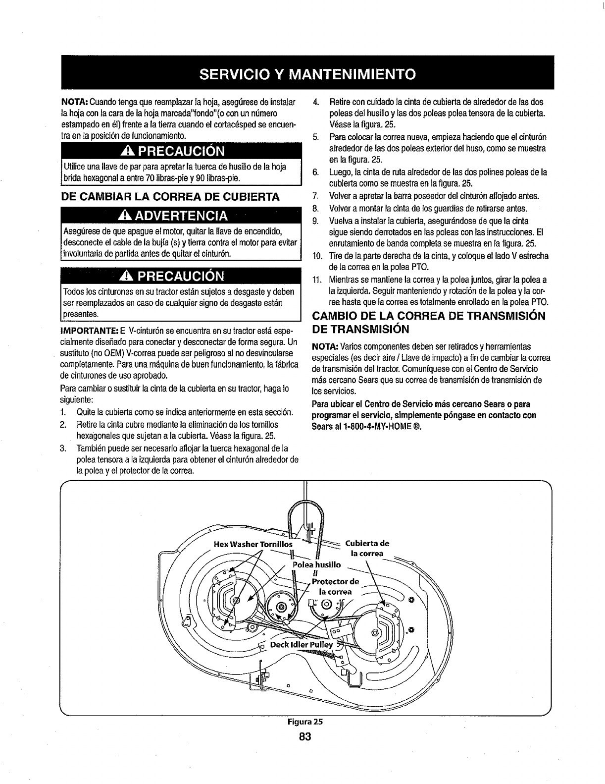
NOTA:Cuandotengaquereemplazarla hoja,asegL_resedeinstalar
la hojacontacaradelahojamarcada"fondo"(oconunnemero
estampadoen_f)frentealatierracuandoel cortac_spedsaencuen-
traenla posici6ndefuncionamiento.
Utiliceunallavedeparparaapretarlatuercadehusil]odelahoja
bridahexagonalaentre70tibras-piey 90libras-pie.
DE CAMBIAR LA CORREA DE CUBIERTA
Vz'YI'_ -'7i [fl I+..I
AsegLiresedequeapagueelmotor,quitarla!lavedeenoendido,
desconecteelcabledelabujfa(s)y tierracontraelmotorparaevitar
invo]untariadepartidaantesdequitarelcintur6n.
4. Retireconcuidadolacintadecubiertadealrededordelasdos
poleasdelhusilloy Iasdospoleaspoleatensoradelacubierta.
V_aselafigura.25.
5. Paracolocarlacorreanueva,empiezahaciendoqueelcintur6n
alrededordelasdospoleasexteriordelhuso,comosemuestra
enlafigura.25.
6. Luego,lacintaderulaalrededordelasdospolinespoleasdela
cubiertacomosemuestraenlafigura.25.
7, Volveraapretarlabarraposeedordelcintur6naflojadoantes.
8. Vo]vera montarlacintadelosguardiasderetirarseantes.
9. Vuelvaainstalarlacubierta,asegur_ndosedequelacinta
siguesiendoderrotadosenlaspoleasconlasinstrucciones.El
enrutamientodebandacompletase muestraenlafigurao25.
10. Tiredelapartederechadelacinta,y coloqueelladoV estreeha
deta correaenlapoleaPTO.
11. Mientrassemantienelacorreay la poleajuntos,girarlapoleaa
laizquierda.Seguirmanteniendoy rotaci6ndela poleay lacot-
teahastaquelacorreaestotalrnenteenrolladoenla poleaPTO.
V:'Wt-_+:t +i
IMPORTANTE: ElV-cintur6n se encuentra en su tractorestdespe-
cialmente disefiado para eonectary desconectarde forma segura. Un
sustituto (no OEM) V-correa puedeser peligroso al no desvincularse
completamente.Parauna mdquinade buenfuncionamiento, laf&brica
de cinturonesde usoaprobado.
Paracambiaro sustituirla cinta de la cubierta en su tractor,haga Io
siguiente:
1. Quite la cubierta como se indicaanteriormenteenesta secci6n.
2. Retire la cintacubre mediantela eliminaci6nde los tornil]os
hexagonalesque sujetan a la cubierla.V_ase la figura. 25.
3. Tambi6npuedeset necesarioaflojar la tuerca hexagonalde la
poleatensora a Ia izquierdaparaobtener el cintur6n alrededor de
]apolea y el protectorde lacorrea.
CAMBIO DE LA CORREA DE TRANSMISION
DE TRANSMISI6N
NOTA-'Varioscomponentesdebenserretiradosy herram!entas
especiales(esdeciraireILlavedeimpacto)afindecambiarlacorrea
detransmisi($ndeltractor.Comun[quesecone[CentrodeServicio
m&scercanoSearsquesucorreadetransmisi6ndetransmisi6nde
losservicios.
Paraubicarel CentrodeServiciom_scercanoSearso para
programarel servicio,simplementep6ngaseen contactocon
Searsal 1-800-4-MY-HOME®.
Cubierta de
la €orrea
Figura 25
83
Nunoaalmacenetractordec6spedconcombustibleeneltanque
enunespaciocerradooen_.reasconpocaventilaci6n,dondelos
gasesdelcombustiblepuedanalcanzarelfuego,chispasounaluz
pilotocomolaquetienenalgunoshomos,calentadoresdeagua,
secadoresderopaoalgenotrodispositivoa gas.
PREPARACION DEL MOTOR
IMPORTANTE:Elcombustiblequequedaene!tanquecuandohace
caforse deterioray ocasionagravesproblemasdeencendido.
Paraevitar que se formen dep6sitos degoma dentro del carburador
dei motory posibtesdesperfectosen el motor, e] sistema de combus-
tible debeset vaciado completamente,o se debe tratar la gasotinacon
un estabilizador para evitarel deterioro.
1. Si utiliza unestabilizadorde combustible:
a. Lea lasinstruccionesy recomendacionesdel fabricantedel
producto.
b. Agregueia cantidad correctade estabilizadorparala
capacidaddel sistema de combustible a gasolinatimpiay
IIueva.
c. Llene el dep6sitode combustible con combustibletratado
y haga funcionarel motor 2-3 minutosparaestabilizar el
combustibledentro de] carburador.
4. Cuandovacie el sistemade combustible:
a. No drene el combustiblecuando el motor est,. ca]iente.
Permitaque el motorse enfdebien. Drene el combustible
dentro de un recipienteaprobadoy al aire libre, lejos de
cualquier llama expuesta.
b. Drene ungran volumende combustibledesdee] dep6sito,
desconectandoia Ifneade combustible del filtrode combus-
tible en lineaque se encuentm cerca de]motor.
c. Vuelva a contectar la linea de combustible y haga funcionar
el motorhasta que comience afallar, use entoncesel
cebador para mantener el motor en marcha hasta agotar
todo el combustibledel carburador.
d. Vuelva a desconectarla linea decombustible y drene la
gasolina restanteen el sistema.
5. Extraiga la bujia y vierta una (1) onzade aceitepara motor pot el
orificio de la bujia enel cilindro. Hagagirar el motor variasveces
paradistribuirel aceite.Vuelva a colocar la bujia.
EL DRENAJE DE LOS COMBUSTIBLES
1. Localiceel fiitro de combustible,que se encuentraen el lado
izquierdodel motor,y puedeser conectado al motor conuna
correa de empate.
2. Cortarla correa dela corbata, si est_presente,entoncesemer-
gente enla abrazaderaen Jrneaen el filtro decombustible con un
Lagasoiinaesuna sustanciat6xica.Eliminela gasolina
adecuadamente.Comuniqueseconlas autoridadeslocalespara
averiguarcuries sonlosm_todosadecuadosparaelirninarla gasolina.
par de alicates, deslicela abrazaderade la linea decombustible.
3. Quite la Iinea decombustible en la linea y tafuga de combustible
en un recipienteaprobado.
PREPARACION DE LA TRACTOR DE ClaSPED
•Limpiey lubriquelatractorcomosedescribeenlas instruccionesde
lubricaci6n.
•Noutiliceuna lavadoraa presi6nni unamangueradejardin para
lirnpiarsu unidad.
•Almacenelatractor en unazonalimpiay seca.Nola almacenecerca
dematerialescorrosivoscomopotejemplofertilizantes.
ILk ir;' IEw ,tl I, ""
Lagasolinaes sumamenteinflamabley puedeserexplosivaen ciertas
condiciones.Vaciela antesde almacenarelequipoduranteperiodos
prolongados.Dreneel combustible Onicamentedentro de un
recipienteaprobadoy al aire fibre, lejos de cualquierllamaexpuesta.
Deje que el motorse enfrie. Antes de drenarel combustible,apague
cigarrillos,cigarros, pipasy otrasfuentes de combusti6n.Vaciela
gasolinaen un_reabienventitada,lejosde cualquiertuentedellama
o chispas,inclufdocuatquierartefactoconluzpiloto.Almacenela
gasoiinaen unrecipienteaprobado,enunlugarseguro.
84
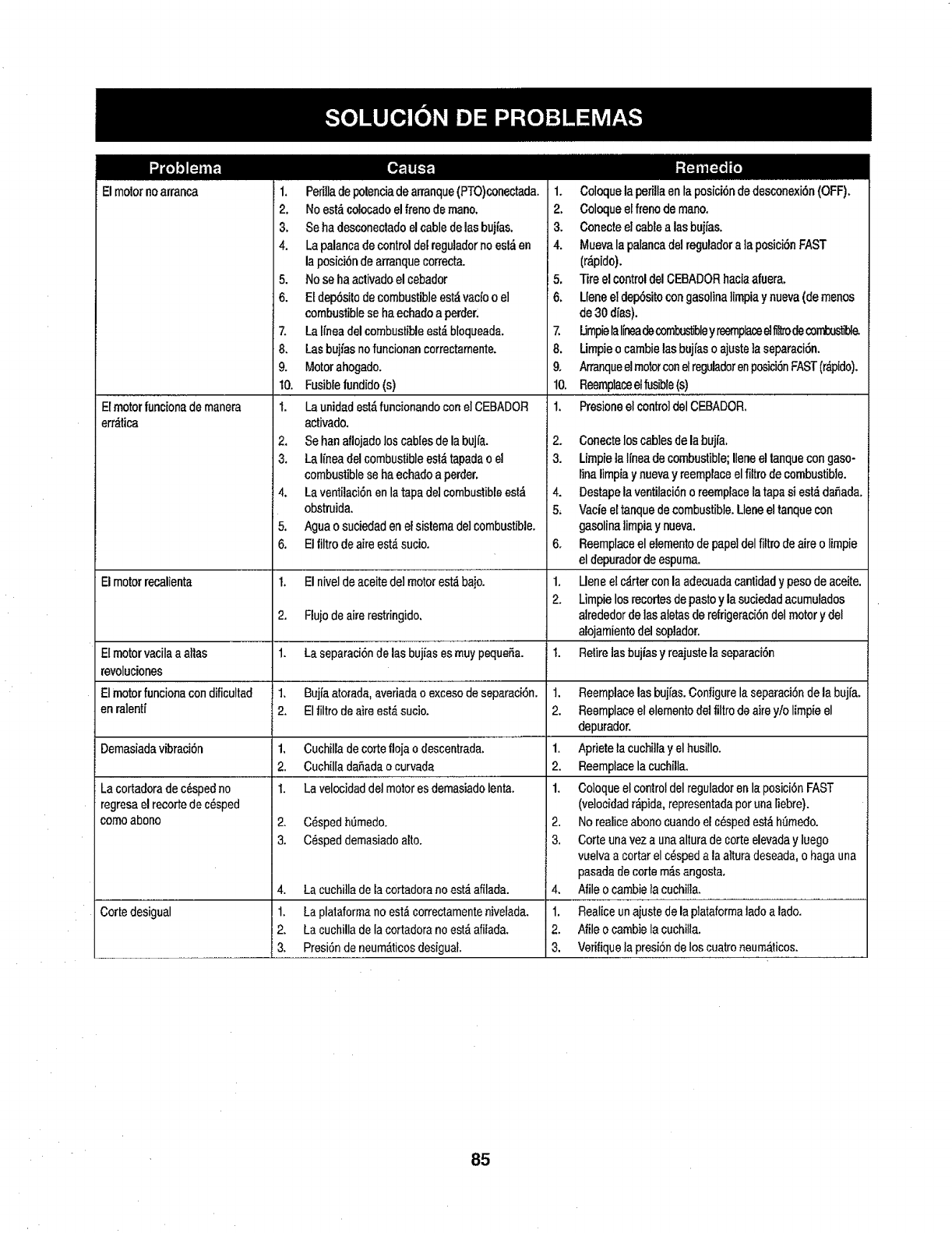
El motornoarranca
Elmotorfuncionademanera
erotica
1. Perilladepotenciadearranque(PTO)conectada,
2. Noest_colocadoelfrenodemane.
3, Seha desconectadoelcabledelasbujfas.
4. Lapalancadecontroldelreguladornoest_en
lapesici6ndearranquecorrecta.
5. Nose ha activadoelcebador
6. Etdep6sitodecombustibleest_vacfoo el
combustiblese haechadoa pettier.
7, Latfneadel combustibleest,.bloqueada.
8. Lasbuj/asno funcionancorrectamente.
9. Motorahogado.
10. Fusiblefundido(s)
t. Launidadest_funcionandoconelCEBADOR
activado.
2. Sehenaflojadoloscablesdelabujfa.
3. LaIfneadelcombustibleesl&tapadao el
combustibleseha echadoa perder,
4. Laventilacidnenlatapadelcombustibleest_
obstruida,
5. Agueo sudedadenelsistemade]combustible.
6. E!filtrodeaireest,_sucio,
1, Coloquelaperillaenlaposici6ndedesconexi6n(OFF).
2, Coloqueelfrenodem_o.
3, Conecteelcablealas bujfas.
4. Muevalapalancadel reguladorala posici6nFAST
(r,_pido),
5, TireelcontroldelCEBADORhaciaafuera,
!6. Lleneeldep6sitocongasolinelimpiay nueva(de menos
de30dfas).
7, UmpielaIfneadecombustibleyreernplaced fi_ decontxsb_&
8, Umpieocambielasbujfaso ajuste]aseparacidn.
9, ArranqueelmotorconelreguladorenposicidnFAST(r&pido),
10, Reemplaceelfusible(s)
1. Presioneelcontroldel CEBADOR.
2.
3.
4.
5,
as
Elmotorrecalienta 1. Elnive]deaceitedelmotorest,,bajo. 1,
2.
2. Flujodeairerestringido,
Elmotorvacilaa alias 1. La separaci6ndelasbujfasesmuypequeSa. I.
revoluciones
Elmotorfuncionacondificultad 1, Bujfaatorada,averiadao excesodeseparacl6n, 1.
enralentf 2, El_tro deaireest&suc]o. 2.
Demasiadavibraci6n 1, Cuchilladecorteflojao descentrada. 1.
2. CuchilladaSadao curvada 2.
I. Lavelocidaddetmotoresdemasiadolenta. 1.
2. C_sped h0medo.
3. Cdspeddemasiadoalto.
Lacortadoradec_spedno
regresaelrecortedecdsped
come abono
Cortedesigual
4. Lacuchilladelacortadoranoest_afilada.
1. Laplataformano est_correctamentenivelada,
2, LacuchilladeIacortadoranoest&afiiada,
3, Presidndeneum&ticosdesigual.
Conecteloscablesdela bujia.
Limpieta I[neade combustible;Ileneeltanquecongaso-
tinalimpiay nuevay reemplaceelfiltrodecombustible.
Destapela ventilaci6no reemplacelatapasiest_daSada.
Vacieeltanquedecombustible,Lleneeltanquecon
gasolinalimpiaynueva.
Reemplaceel elementodepapeldelfiltrodeaireo limpie
eldepuradordeespuma.
Lleneel c_rterconlaadecuadacantidadypesodeaceite.
Limpielosrecortesde pastey lasuciedadacumufados
alrededordelasaletasderefrigeraci6ndel motory del
alojamientodelsoplador.
Retirelasbujiasy reajustelaseparacidn
Reemplacelasbujfas.Configurelaseparaci6ndela bujfa,
Reemplaceel elementodeltiltrodeairey!o limpieel
depurador.
Aprietelacuchitfay elhusillo.
Reemplacela cuchilla.
Coloqueelcontroldel reguladorenlaposici6nFAST
(velocidadr_pida,representadaperunaliebre).
2. Norealiceabonocuandoel cdspedest_ht_medo.
3. Corteunaveza unaalturadecorteelevaday luego
vuelvaa cortarelc_spedala atturadeseada,o hagauna
pasadadecortern_sangosta,
4, Nileo cambietacuchilla,
1, Realiceunajustedelaplataforrnaladea lade.
2. Nile o cambieIscuchilla.
3. Verifiquelapresidndeloscuatroneumaticos.
85

This page intentionally left blank. Use this page to make any notes regarding your tractor.
86
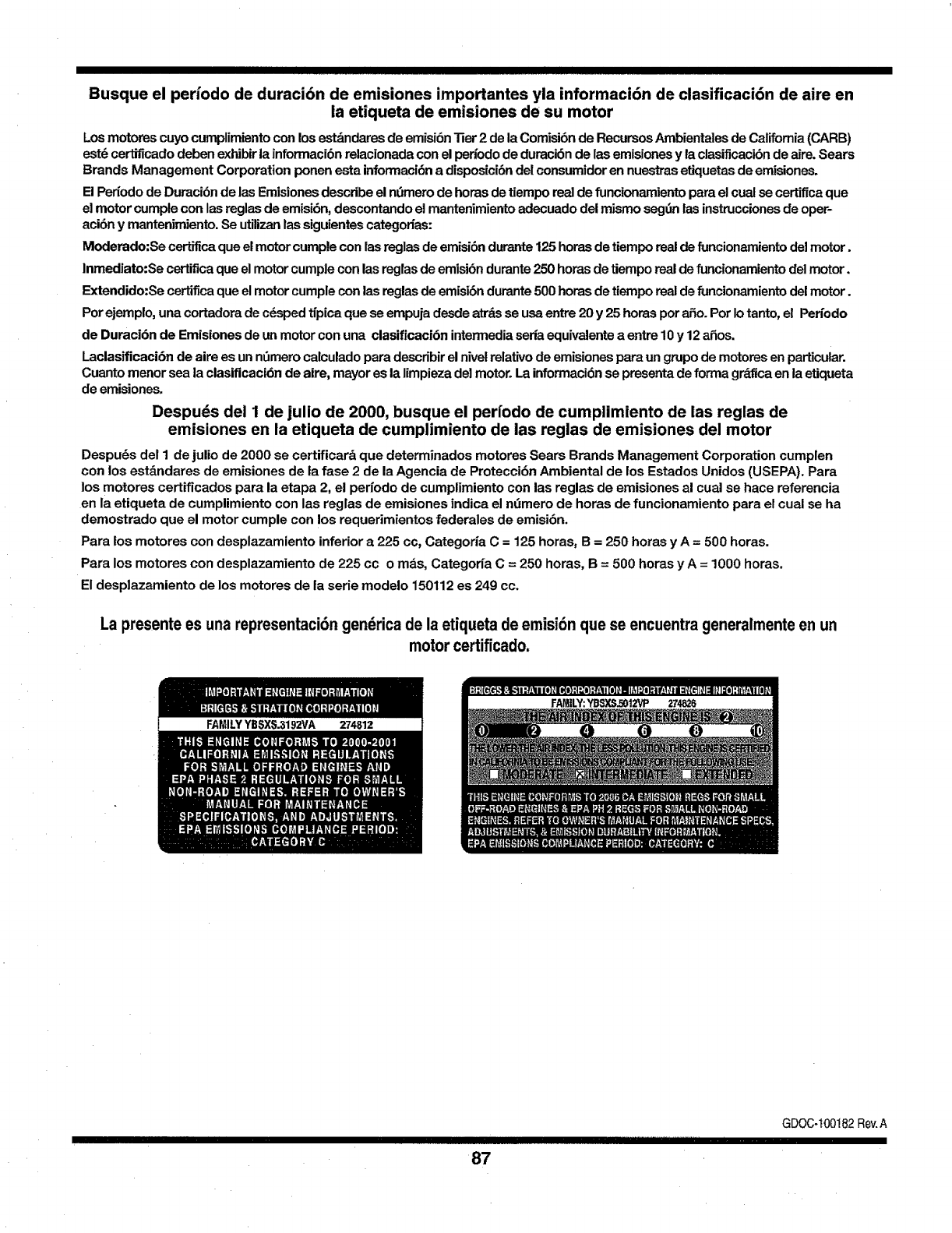
IIII I I [ II III IJ I
Busque el periodo de duraci6n de emisiones importantes yla informaci6n de clasificaci6n de aire en
la etiqueta de emisiones de su motor
Los motoms cuyo cumpfimientocon los e_'tdndaresde emisi6n Tier2 de la Comisi6n de RecursosAmbientalesde Califomia(CARB)
est_ cerlfficado deben exhibitla inforrnaci6nrelacionada con el per/ode de duraci6nde las emisionesy la clasificacibnde aire. Sears
Brands Management Corporation ponen esta informaci6na disposici6ndel consumidoren nuestrasetiquetas de emisioneso
El Per_odode Duraci6n de las Emisionesdescdbe elnt_merode heras de tiempo real de funcionamiento parael cual se certiflca que
el motor cumple con lasreglas de emisi6n, descontando el mantenimientoadecuado del mismo segfin las instruccionesde oper-
aci6n y mantenimiento.Se utilizanlassiguientescategodas:
Moderado:Se certificaque el motorcumple con lasreglasde emisi6ndurante125 hems de tiempo real de funcionamientodel motor.
Inmediato:Se certificaque el motor cumple con las reglasde emisibndurante250 horasde tiempo real de funcionamientodel motor.
Extendido:Se certifica que el motorcumplecon ias reglas de emisi6ndurante500 horas de tiempo real de funcionamientodel motor.
Por ejemplo, una cortadorade c_sped tfpica que seempuja desde atrdsse usa entre 20 y 25 horas pot a_o. Pot Io tanto,el Pen'odo
de Duraci6n de Emisiones de un motor con una clasificaci6n intermediaseria equivalente aentre 10y 12afios.
Laclasificaci6n de aire es un nfimerocalculado para describirel nivelrelativode emisionespara un grupo de motores en particular.
Cuanto menor sea la clasificaci6n de aire, mayor es ia limpieza del motor. La informaci6nse presenta de forma gr&flcaen la etiqueta
de emisiones.
Despuds del I de julio de 2000, busque el per{odo de cumplimiento de las reglas de
emisiones en la etiqueta de cumplimiento de las reglas de emisiones del motor
Despu_s del 1 de julio de 2000 se certificar& que determinados motores Sears Brands Management Corporation cumplen
con los estdndares de emisiones de la fase 2 de la Agencia de Protecci6n Ambiental de los Estados Unidos (USEPA). Para
los motores certificados para la etapa 2, el per{odo de cumplimiento con las reglas de emisiones al cual se hate referencia
en la etiqueta de cumplimiento con las reglas de emisiones indica el n_mero de horas de funcionamiento para el cual se ha
demostrado que el motor cumple con los requerimientos federales de emisi6n+
Para los motores con desplazamiento inferior a 225 cc, Categoria C = 125 horas, B = 250 horas y A = 500 horas.
Para los motores con desplazamiento de 225 cco mas, Categorfa C = 250 horas, B=500 horas y A = 1000 horas.
El desplazamiento de los motores de la serie modelo 150112 es 249 cc.
La presentees unarepresentaci6ngen_ricadelaetiquetadeemisi6nquese encuentrageneralmenteen un
motorcertificado.
I'111111111111111111111'1111'111111111111111I
87
GDOC-100182 Rev.A
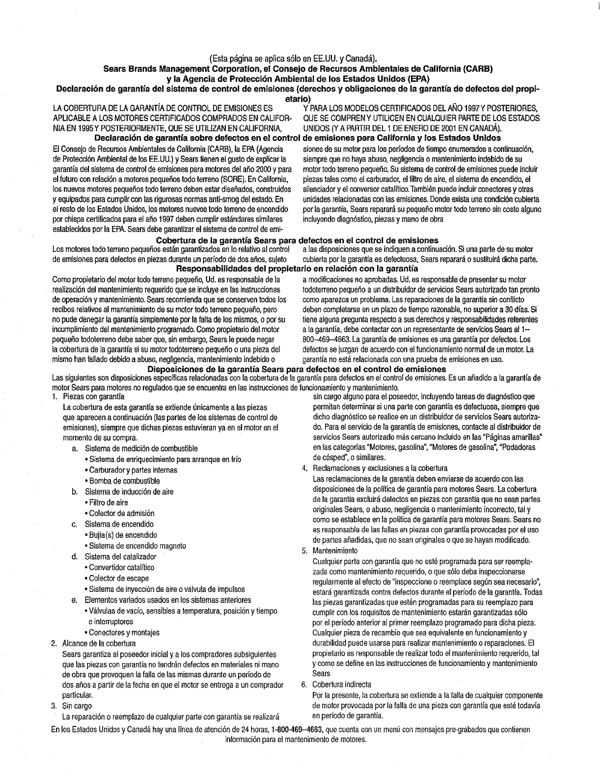
(Esta p&ginase aplicas61oen EE.UU.yCanad&).
Sears Brands Management Corporation, el Consejo de Recursos Ambientales de California (CARB)
y la Agencia de Protecci6n Ambiental de los Estados Unidos (EPA)
Declaracibn de garantia de! sistema de control de emisiones (derachos y obligaciones de la garantfa de defectos de! propi-
etario)
LACOBERTURADELA GARANT[ADECONTROLDEEMIS]ONESES Y PARALOSMODELOSCERTIFICADOSDELN_IO1997YPOSTERIORES,
APLICABLEA LOSMOTORESCERTIFICADOSCOMPRADOSENCALIFOR-
NIAEN1995YPOSTERIORMENTE,QUESEUTIUZANENCALIFORNIA,
Declaraci6n de garantia sobre defectos en el control
EiConsejodeRecursosAmbientalesde California(CARB),laEPA(Agencia
deProtecci6nAmbientaldelosEE.UU.)ySearstienenelgustodeexplicarla
garantfadelsistemadecontroldeemisionesparamotores(telaSo2000y pare
elfuturoconrelaci6na motorespeque_ostodoterreno(SORE).EnCalifornia,
losnuevosmotorespequefi0srod0terren0debenesterdise_ados,construidos
yequipadosparecumplirconlasrigurosashermesanti-smogdelestado.En
el restodelosEstadosUnidos,losmotoresnuevostodoterrenodeencendido
potchispacertiticadosparaela_o1997debencumplirest_ndaressimilares
eslablecidosperlaEPA.Searsdebegarantizarelsistemadecontrolde emi-
QUESECOMPRENY UTILICENENCUALQUIERPARTEDELOSESTADOS
UNIDOS(Y A PARTIRDEL1 DEENERODE2001ENCANADa,).
de emisiones para California y los Estados Unidos
sionesdesumotorparelosper[odesdetiempoenumeradosa continuaci6n,
siemprequenohayaabuso,negligenciao mantenimientoindebidodesu
motortodoterrenopequeSo.Susistemade controldeemisionespuedeincluir
piezastalescomoelcarburador,elfiltrodeaire,elsistemade encendido,el
silenciadory elconversorcatal[tico.Tambi_npuedeincluirconectoresyotras
unidadesrelacionadasconlasemisiones.Dondeexistaunacondici6ncubierta
porlagarantia,Searsreparar_su pequefiomotortodoterrenosincostoalguno
incluyendodiagn6stico,piezasymanodeobra
Cobertura de la garantia Sears para defectos en el control de emisiones
Losmotorestodoterrenopeque_osest_ngarantizadosenIorelativoalcontrol alas disposicionesqueseindiquenacontinuaci6n.Siunapartedesumotor
deemisionesparedefectosenpiezasduranteunperiododedoeaSos,sujeto cubiertaporlagarantl'aesdefectuosa,Searsreparar_osustituir_,dichaparte.
Responsabilidades del propietario en relacion con la garantia
Comopropietariodel motorredoterrenopequeSo,Ud.esresponsabledela
realizaci6ndel mantenimientorequeridoquese incluyeenlasinstrucciones
deopemci6ny mantenimiento.Searsrecomiendaqueseconserventodoslos
recibosrelativosal mantenimientodesumotortodoterrenopequeSo,pero
nopudedenegarlagarantiasimplementepotlafaltadelosmismos,oporsu
incumplimientodel mantenimientoprogramado.Comopropietariodelmotor
pequeSotodoterrenodebesaberque,sinembargo,Searslepuedenegar
lacoberturadela garantfasi sumotortodoterrenopequeSoo unapiezadel
mismohenfalladodebidoaabuso,negligencia,mantenimientoindebidoo
a modificacionesnoaprobadas.Ud.esresponsabledepresentersumotor
todoterrenopequeSoa undistribuidordeserviciosSearsautorizadotanpronto
comoaparezcaunproblema.Lasreparacionesdelagarantiasinconflicto
debencompletarseen unplazodetiemporazonable,nosuperiora 30dfas.Si
tienealgunapreguntarespectoa susderechosy responsabilidadesreferentes
ala garantfa,debecontactarconunrepresentantedeser¢iciosSearsal 1-
800--469-4663.Lagarantfadeemisionesesunagarantiapotdefectos.Los
defectossejuzgandeacuerdoconelfuncionamientonormaldeunmotor.La
garantianoest_relacionadaconunapruebadeemisionesenuso.
Disposiciones de la garantia Sears para defectos en el control de emisiones
Las siguienfessondisposicionesespecificasrelacionadasconla coberturadelagarantiaparedefectosenelcontroldeemisiones.EsunaSadidoata garantfade
motorSearsparemotoresnoreguladosquese encuentraenlasinstruccionesdeiuncionamientoy mantenimiento.
t. Piezascongarantia
Lacoberturadeestagarantfase extiende0nicamentealas piezas
queaparecena continuaci6n(laspartesdelossistemasdecontrolde
emisiones),siemprequedichaspiezasestuvieranyaenelmotorenel
rnornentodesucompra.
a. Sistemademedici6ndecombustible
• Sistemadeenriquecimientoparearranqueentrio
•Carburadory partesinternes
•Bombadecombustible
b. Sistemadeinducci6ndeaire
• Filtrode aire
•Colectordeadmisi6n
c. Sistemadeencendido
•Bujia(s)deencendido
•Sistemadeencendidomagneto
d. SistemadeIcatalizador
•Convertidorcatalitico
•Colectordeescape
•Sistemadeinyecci6ndeaireov_.Ivutade impulsos
e. Elementosvariadosusadosenlossistemasanteriores
,V&lvulasdevacfo,sensiblesatemperatura,pesici6nytiempo
e interruptores
•Conectoresy montajes
2. Alcancede la cobertura
SearsgarantizaaIposeedorinicialy a loscompradoressubsiguientes
quelaspiezascongarantianotendr_ndefectosenmaterialesnimano
deobraqueprovoquenlafalladelasmismasduranteunperiodode
dosamosa partirdelafechaenqueelmotorseentregaa uncomprador
particular.
3. Sincargo
Lareparaci6no reemplazodecualquierpartecongarantfase realizar,_
sin cargoalguno pare el poseedor, incluyendotareas de diagn6stico que
permitan determinar si una parte con garantia es defectuosa, siempre que
dicho diagn6stico se realice en un distribuidor de servicios Sears autoriza-
do. Pare el servicio de la garantia de emisiones, contacte al distribuidor de
servicios Sears autorizado m_s cercano incluido en las "P_ginas amarillas"
en las categories "Motores, gasoline", "Motores de gasoline, "Podadoras
de c_sped", o simUares.
4. Reclamaciones y exclusionesala cobertura
Las reclamaciones de la garantia deben enviarse de acuerdo con las
disposiciones de la politica de garantia pare motores Sears. La cobertura
de la garantia excluir_ de|ectos en piezas con garantia que no seen partes
originales Sears, o abuso, negligencia o mantenimiento incorrecto,tel y
como se establece en la politica de garantia pare motores Sears. Sears no
es responsable de las fallas enpiezas con garantia provocadas por el uso
de partes afiadidas, que no sean originales o que se hayanrnodiiicado.
5. Mantenimiento
Cuafquier parte con garantia que no est,, programada pare ser reempta-
zada como mantenimiento requerido, o que s61odeba inspecoionarse
regularmente a] efecto de "inspeccione oreemplace seg_n sea necesario",
estar_,garantizada centre defectos durante el periodo de la garantfa. Todas
las piezasgarantizadas que est_n prograrnadaspare su reemplazo para
cumplir con los requisitos de mantenirniento estar_.ngarantizadas s61o
per el periodo anterior al primer reemplazo programado pare dicha pieza.
Cualquier pieza de recarnbio que sea equivalente en funcionamiento y
durabilidad puede usarse para realizer mantenimiento oreparaciones. El
propietario es responsable de realizer todo el mantenimiento requerido, tal
y como se define en Ias instrucciones de funcionamiento y mantenimiento
Sears
6. Cobertura indirecta
Per Ia presente, Ia cobertura se extiende ala fafla de cualquier componente
de motor provocadapot fa falla de una pieza con garantfa que est_ todav_a
en periodo de garantia.
EnlosEstadosUnidosy Canada_hayunalfneade atenci6nde24horas,1-800-469-4663,quecuentaconunmen0conmensajespre-grabadosquecontienen
informaci6npareet mantenimientode motores.
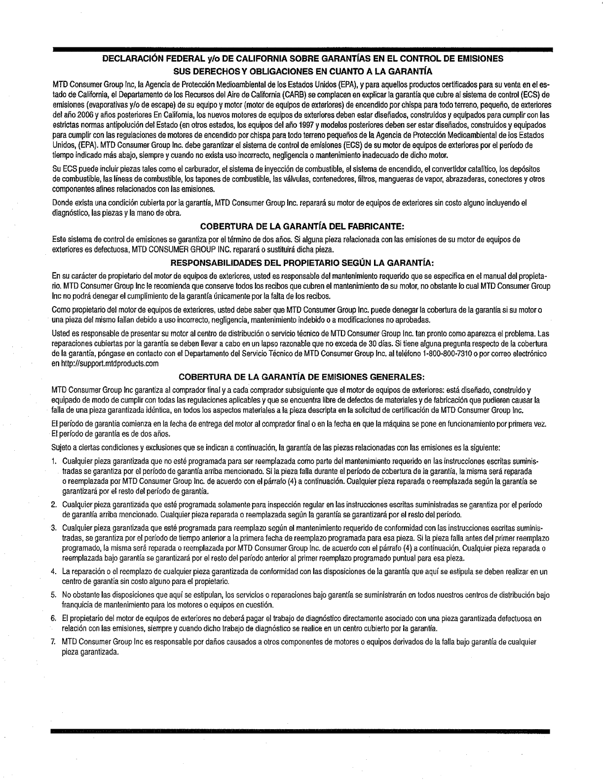
DECLARACION FEDERAL ylo DE CALIFORNIA SOBRE GARANT|AS EN EL CONTROL DE EMISIONES
SUS DERECHOS Y OBLIGAClONES EN CUANTO A LA GARANTiA
MTDConsumerGrouplnc,la AgenciadeProtecci6nMedioarnbientalde losEstadosUnidos(EPA),y pareaquellosproductoscertificadosparesuventaenetes-
tadodeCalifornia,el DepartamentodelosRecursosdelAiredeCalifornia(GARB)secomplacenenexplicarlagarantiaquecubrealsistemadecontrol(ECS)de
emisiones(evaporativasy/odeescape)desuequipoy motor(motordeequiposdeexteriores)deencendidoperchispaparatodoterreno,peque_o,deexteriores
delaSo2006ya_osposterioresEnCalifornia,losnuevosmotoresdeequiposdeexterioresdebenesterdisefiados,construidosyequipadosparacumplirconlas
estrictasnormasantipoluci6ndelEstado(enotrosestados,losequiposdela_o 1997ymodelosposterioresdebenserestardise_ades,construidosy equipados
paracumplirconlasregulacionesdemotorosdeencendidoperchispaparetodoterrenopeque_osdelaAgenciadeProtecci6nMedioambienteldetosEstados
Unidos,(EPA).MTDConsumerGroupinc.debegarantizarelsistemadecontroldeemisiones(ECS)desumotordeequiposdeexterioresperel periodode
tiempoindicadom_sabajo,siernprey cuandonoexistauseincorrecto,negligenciaornantenirnientoinadecuadodedichomotor.
SuECSpuedeincluirplazastalescomoelcarburador,el sistemadeinyecci6ndecombustible,elsistemadeencendido,elconvertidorcatalffico,losdep6sitos
decombustible,lasIineasdecombustible,lostaponesdecombustible,tasv&lvulas,contenedores,filtros,manguerasde vapor,abrazederas,conectoresy otros
componentesafinesrelacionadosconlasemisiones.
Dondee×istaunacondici6ncubiertapotia gerantia,MTDConsumerGroupInc.reparar__sumotordeequiposde exterioressincostoalgunoincluyendoel
diagn6stico,laspiezasylemenodeobra.
COBERTURA DE LA GARANTfA DEL FABRICANTE:
Estesistemadecontroldeemisionesse garantizaperelt_rminodedos a_os.Sialgunapiezarefacionadaconlasemisionesdesu motordeequiposde
exterioreses defectuosa,MTDCONSUMERGROUPINC.reparar_o sustituir_dicbapieza.
RESPONSABILIDADES DEL PROPIETARIO SEGUN LA GARANT|A:
Ensucar_cterdepropietariodelmotordeequiposde exteriores,ustedesresponsabledelmantenimientorequeridoqueseespecificaenelmanualdelpropieta-
rio.MTDConsumerGroupInclerecomiendaqueconserveredeslosrecibosquecubrenelmantenimientodesumotor,noobstanteIocualMTDConsumerGroup
inc nopodr__denegarel cumplimientodelagaranffa0nicamenteporlafaitadelosrecibos.
Comopropietario(telmotordeequiposdeextedores,usteddebesaberquaMTDConsumerGroupInc.puededenegarIacoberturade tagarantiasi sumotoro
unapiezadal mismo|allandebidoa usoincorrecto,negligencia,rnantenimientoindebidoo a rnodificacionesnoaprobadas.
Ustedes responsablede presentarsu motoralcentrode distribuci6no serviciot_cnicodeMTDConsumerGroupInc.tanprontocomoaparezcaelproblema.Las
reparacionescubiertasporlagerentiase debenIlevare caboenunlapsorazonablequeno excedade30dies.Sitienealgunapreguntarespectodelacobertura
delagarantie,p6ngaseen contactoconel Departamentodel ServicioT_cnicode MTDConsumerGroupInc.al tel_fono1-800-800-7310o porcorreoelectr6nico
enhttp:/lsupport.rntdproducts.com
COBERTURA DE LA GARANT|A DE EMtSIONES GENERALES:
MTDConsumerGroupIncgarantizaatcompradorfinaly a cadacompradorsubsiguientequeelmotordeequiposdeexteriores:est_dise_ado,construidoy
equipadodemodode curnpiircontodaslasregu]acionesaplicablesyquaseencuentraIibrededefectosdematerialesyde fabricaci6nquepudierencausarla
falla de unapiezagarantizadaid6ntica,entodoslosaspectosmaterialesa lapiezadescriptaonlasolicituddecertificaci6ndeMTDConsumerGroupInc.
Elperiodode garantiacornienzaen lafechade entregadel motoralcornpradorfinalo en lefechaenquela m_quinaseponeenfuncionamientopotprimeravez.
Elperiodode garantiaesdedosaSos.
Sujetoaciertascondicionesyexclusionesquaseindicana continuaci6n,lagarantradelaspiezasrelacionadasconlasemisioneseslasiguiente:
1. Cualquierpiezagarantizadaquanoest6programadaparaserreemplazadacomoportedelrnantenimientorequeridoen lasinstruccionesescritassurninis-
tradasse garantizaporelperiododegaranffaarribamencionado.Sila piezefa[laduranteetperiododecoberturade]egarantia,larrnisrnaser_,reparada
oreemplazadapor MTDConsumerGroupInc.de acuerdoconelp&rrafo(4)a continuaci6n.Cualquierplazareparadeo reemplazadasegLinla garantiase
garantizar_,porel restodelperiododegaranti'a.
2. Cualquierpiezagarantizadaqueest_programadasolamenteparainspecci6nregu]arenlasinstruccionesescritassuministradasse garentizapotelperiodo
degarantiaarribamencionado.Cuatquierpiezareparadaoreemplazadaseg_nlagamntiasegarantizar_por elrestodel periodo.
3. Cualquierplazagarantizadaqueest_programadaparareemplazoseg_nel mantenimientorequeridodeconformidadconlasinstruccionesescritassuminis-
tradas,se garantizaporel pen'ododetiempoanteriora laprimerafechado reernplazoprogramadaparaesapieza.Si]a piezefallaantesdelprimerreemplazo
programado,lamismaser_,reparadao reemplazadaporMTDConsumerGroupInc.deacuerdocon elp_,rrafo(4) acontinuaciSn.Cualquierplazareparadao
reemplazadabajogarantiasegarantizar_porel restodelpeffodoanterioralprimerreemplazoprogramadopuntualpareesapieza.
4. Lareparaci6no elreemplazode cualquierpiezagarantizadadeconformidadcon lasdisposicionesdela garanffaquaaquiseestipulasedebenrealizarenun
centrodegarantiasincostoalgunoparaelpropietario.
5. Noobstantelasdisposicionesqueaquise estipulan,losserviciosoreparacionesbajogarant[asesurninistrar_nentodosnuestroscentrosdedistribuci6nbejo
franquiciadernantenimientoparalosmotoresoequiposencuestibn.
6. Elpropietariodel motorde equiposdeexterioresnodeber_pagere]trabajodediagn6sticodirectamenteasociadoconunapiezagarantizadadefectuosaen
relaciSnconlag emisiones,siemprey cuandodichotrabajodediagnSsticoserealiceenuncentrocubiertopotlagarantia.
7. MTDConsumerGroupIncesresponsablepordaSoscausadosa otroscomponentesdernotoreso equiposderivadosdelafallabajogarantfadecua]quier
piezagarantizada.
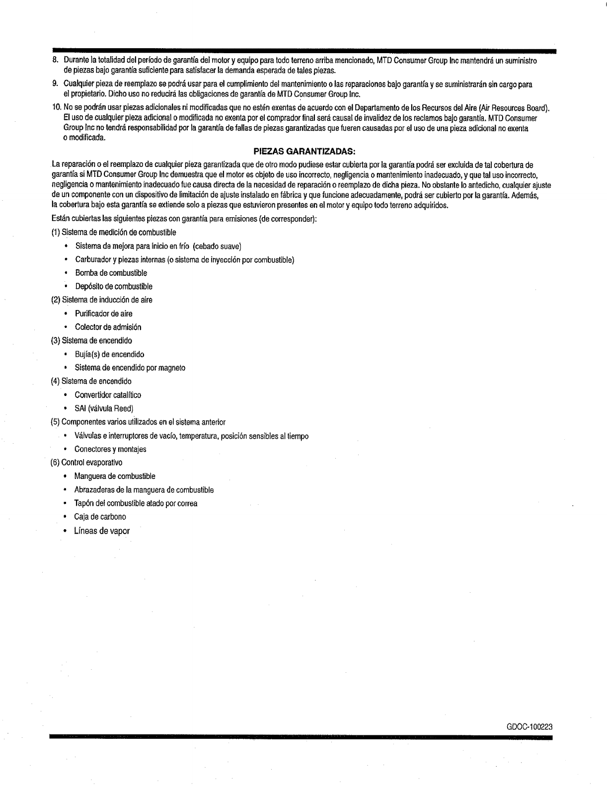
IIIII I I II
8. Ourantelatotalidaddelper_ododegarantfade}motory equipopararodeterrenoarribamencionado,MTDConsumerGroupIncmantendr_unsuministro
depiezasbajogarantiasuficienteparasatisfacerlademandaesperadadetalespiezas,
9. Cualquierpiezade reemplazose pedrO,usarparael cumplimientodelmantenimientoo lasreparacionesbajogarantt'ay sesuministrar_nsincargopara
elpropietario.Dichousenoreducir_lasobtigacionesdegarantfadeMTDConsumerGroupInc,
10,Nosepodr_nusarpiezasadicionalesnimodificadasquenoest_nexentasdeacuerdoconel DepartamentodelosRecursosdelAire(Nr ResourcesBoard).
Elusedecualquierpiezaadicionalo modificadanoexentaperelcempradorfinalser_causa_deinvatidezdelosreclamosbajogarantia.MTDConsumer
Grouplnc notendr_responsabilidadperlagarantiadefa!lasdepiezasgarantizadasquefuerencausadasperel usedeunapiezaadicionalnoexenta
o modificada,
PIEZAS GARANTIZADAS:
Lareparaci6no el reemplazodecualquierpiezagarantizadaquedeotromodepudieseestarcubiertaperla garantfapodrdserexcluidadetalcoberturade
garanti'asiMTDConsumerGroupIncdemuestraqueelmotores objetodeuseincorrecto,negligenciaomantenimientoinadecuado,y quetaluseincon'ecto,
negligenciaomantenimientoinadecuadofuecausadirectadela necesidaddereparaci6no reempiazodedichapieza.NoobstanteIoantedicho,cualquierajuste
deuncomponenteconundispositivodelimitaci6ndeajusteinstaladoenfdbricayquefuncioneadecuadamente,pedrO,setcubiertoperlagarantia.Adem_s,
lacoberturabajoestagarantiaseextiendesoloa piezasqueestuvieronpresentesenel motoryequipotodoterrenoadquiridos.
Estdncubiertaslassiguientespiezascongarant/aparaemisiones(decorresponder):
(1)S!stemademedici6ndecombustible
,Sistemademejoraparainicioenfrio (cebadosuave)
• Carburadory piezasinternas(osistemadeinyecci6npercombustible)
, Bombadecombustible
• Dep6sitode combustible
(2)Sistemadeinducci6ndeaire
•Purificadordeaire
°Colectordeadmisi6n
(3)Sistemadeencendido
•Bujia(s)deencendido
,Sistemadeencendidopermagneto
(4)Sistemadeencendido
•Convertidorcatalitico
°SAI(v_lvulaReed)
(5)Componentesvariesutilizadosenel sistemaanterior
= V_Ivulaseinterruptoresdevacfo,temperatura,posici6nsensib]esaltiempo
•Conectoresymontajes
(6)Controlevaporative
• Mangueradecombustible
•Abrazaderasdela mangueradecombustible
• Tap6ndefcombustibleatadopercorrea
°Cajadecarbono
•Lineas devapor
Felicitacionespothaberrealizadounaadquisici6ninteligente.El
productoCraftsman®quehaadquiridoestAdiseSadoy fabricado
parabrindarmuchosaSesdefuncionamientoconfiable,Perocomo
todoslosproductosavecespuederequerirde reparaciones.Esen
esemomentocuandoeldisponerdeunAcuerdodeprotecci6npara
reparacioneslepuedeahorrardineroy problemas.
A continuaci6nsedetafianlospuntosincluidosenelAcuerdo:
• Servicioexpertoprestadopornueslros10,000especialistasen
reparacionesprofesiona]es
• Servicioitimitadosincargoparalaspiezasy la manodeobraen
todaslasreparacionescubiertas
.Reemplazodelproductohasta1500d61aressi noesposible
repararelproductocubierto
, Descuentode10%delprecionormaldelservicioy detaspiezas
relacionadascone!mismoquenoest_ncubiertasporelacuerdo;
adem_s,t0%dei precionormaldelaverificaci6ndemantenimiento
preventivo
•AyudarApidaportel_fono-1oIlamamosResoluci6nR_pida- el
apoyotelef6nicodeunChamuscaal representante.Pienseen
nosotroscomoelmanual"deundueSohablador."
UnavezadquiridoelAcuerdo,puedeprogramareiservlciocon
tans61orealizarunatlarnadatelef6nica,PuedeIlamarencualquier
momentodeldfaodelanocheoprogramarunservicioenlfnea.
ElAcuerdodeProtecci6nde Reparaci6nes unacomprasinriesgo.
Siustedanulaporalgunaraz6nduranteelperfododegarantfade
producto,proporcionaremosunreembolsotleno.O,unreembolso
prorrateadoencualquiermomentodespu_sdelperfododegarantfa
deproductoexpira,iAdquiemhoysuacuerdodeprotecci6npara
reparaciones!
Seaplicandeterminadaslimitacionesy exclusiones.Paraobtener
informaci6nadicionaly preciosen losEstadosUntdosIlameal
1-800-827-6655.
El*Coverageen Canaddvariaenatgunosart|culos.Paradetaltes
IlenoslaIlarnadaCharnuscaCanadaen 1-800-361-6665.
Serviciodeinstalaci6ndeSears
Sideseasolicitarla instalaci6nprofesionaldeSearsdeaparatos
dom_sticos,dispositivosparaabrirportones,calentadoresdeagua
yotrosartfculosdombsticosimportantes,enlos EstadosUnidoso
Canadallameal 1-800-4-MY-HOME®.
91

CRRFTSMRN o
Riding Equipment
questions or problems?
Satisfaction with your purchase
is our number one concern!
To troubleshoot problems,
get answers to questions, order parts,
or schedule repair service for your
Riding Equipment, call the number below.
Para respuestas a preguntas o problemas,
y ordenar piezas o pedir servicio para la
reparacibn de su equipo, Ilame el nOmero abajo.
_iiii 1-800-659-5917
Craftsman Help Line
www.craftsman.com
® Registered Trademark tTM Trademark of KCD IP, LLC inthe United States, or Sears Brands, LLC in other countries
TM
® Marca Registrada /Marca de F&brica de KCD IP, LLC en Estados Unidos, o Sears Brands, LLC in otros paises
