MTD 13AX615G055 User Manual TRACTOR Manuals And Guides 1109240L
User Manual: MTD 13AX615G055 13AX615G055 MTD TRACTOR - Manuals and Guides View the owners manual for your MTD TRACTOR #13AX615G055. Home:Lawn & Garden Parts:MTD Parts:MTD TRACTOR Manual
Open the PDF directly: View PDF ![]() .
.
Page Count: 37

Safe Operation Practices • Set-Up • Operation • Maintenance • Service • Troubleshooting • Warranty
OPER roR's L
Model Series 610 Hydrostatic Lawn Tractor
MTD LLC, P.O. BOX 361131 CLEVELAND, OHiO 44136-0019
PrintedIn USA FormNo.769-03633
(November14,2007)
ToTheOwner 1
ThankYou
Thank you for purchasing a lawn tractor manufactured by
MTD LLC. It was carefully engineered to provide excellent
performance when properly operated and maintained.
Please read this entire manual prior to operating the equipment.
It instructs you how to safely and easily set up, operate and
maintain your machine. Please be sure that you, and any other
persons who will operate the machine, carefully follow the
recommended safety practices at all times. Failure to do so could
result in personal injury or property damage.
All information in this manual is relative to the most recent
product information available at the time of printing. Review
this manual frequently to familiarize yourself with the machine,
its features and operation. Please be aware that this Operator's
Manual may cover a range of product specifications for various
models. Characteristics and features discussed and/or illustrated
in this manual may not be applicable to all models. MTD LLC
reserves the right to change product specifications, designs and
equipment without notice and without incurring obligation.
This product has met the rigid safety standards of the Outdoor
Power Equipment Institute and an independent testing
laboratory. If you have any problems or questions concerning
the machine, phone your local authorized MTD service dealer
or contact us directly. MTD's Customer Support telephone
numbers, website address and mailing address can be found on
this page. We want to ensure your complete satisfaction at all
times.
Throughout this manual, all references to right and left side of the
machine are observed from the operating position
The engine manufacturer is responsible for all engine-related
issues with regards to performance, power-rating, specifications,
warranty and service. Please refer to the engine manufacturer's
Owner's/Operator's Manual, packed separately with your
machine, for more information.
Table of Contents
Safe Operation Practices ........................................ 3
Assembly &Set-Up .................................................. 8
Controls & Features ................................................ 12
Operation ................................................................ 16
Maintenance &Adjustment ................................ 20
Service .................................................................... 24
Troubleshooting .................................................... 29
Replacement Parts ................................................ 30
Attachmen ts & Accessories ................................... 31
CA. Emission Control Statement .......................... 35
Warranty ................................................. Back Cover
RecordProductInformation
Before setting up and operating your new equipment, please
locate the model plate on the equipment and record the
information in the provided area to the right. You can locate the
model plate by standing at the operator's position and looking
down at the tea r of the deck. This information will be necessary,
should you seek technical support via our web site, Customer
Support Department, or with a local authorized service dealer.
MODEL NUMBER
FINFINFINFINFIND
SERIAL NUMBER
DIqDIqDIqDIqDIqD
CustomerSupport
Please do NOT return the machine to the retailer or dealer without first contacting our Customer Support Department.
If you have difficulty assembling this product or have any questions regarding the controls, operation, or maintenance of
this machine, you can seek help from the experts. Choose from the options below:
0 Visit us on the web at www.mtdproducts.com
0 Call a Customer Support Representative at (800) 800-7310 or (330) 220-4683
0 Write us at MTD LLC • RO. Box 361131 • Cleveland, OH • 44136-0019
importantSafeOperationPractices 2
,A
WARNING: This symbol points out important safety instructions which, if not followed,
could endanger the personal safety and/or property of yourself and others. Read and follow
all instructions in this manual before attempting to operate this machine. Failure to comply
with these instructions may result in personal injury.
When you see this symbol. HEED ITS WARNING!
CALIFORNIA PROPOSITION 65
WARNING: Engine Exhaust, some of its constituents, and certain vehicle components
contain or emit chemicals known to State of California to cause cancer and birth defects
or other reproductive harm.
WARNING: Battery posts, terminals, and related accessories contain lead and lead
compounds, chemicals known to the State of California to cause cancer and reproductive
harm. Wash hands after handling
DANGER: This machine was built to be operated according to the safe operation practices in
this manual. As with any type of power equipment, carelessness or error on the part of the
operator can result in serious injury. This machine is capable of amputating hands and feet
and throwing objects. Failure to observe the following safety instructions could result in
serious injury or death.
GeneralOperation
1. Read, understand, and follow all instructions on the
machine and in the manual(s) before attempting to
assemble and operate. Keep this manual in a safe place for
future and regular reference and for ordering replacement
parts.
2. Be familiar with all controls and their proper operation.
Know how to stop the machine and disengage them
quickly.
3. Never allow children under 14 years of age to operate this
machine. Children 14 and over should read and understand
the instructions and safe operation practices in this manual
and on the machine and should be trained and supervised
by an adult.
4. Never allow adults to operate this machine without proper
instruction.
5_ To help avoid blade contact or a thrown object injury,
keep bystanders, helpers, children and pets at least 75 feet
from the machine while it is in operation. Stop machine if
anyone enters the area.
6. Thoroughly inspect the area where the equipment is to be
used. Remove all stones, sticks, wire, bones, toys, and other
foreign objects which could be picked up and thrown by
the blade(s). Thrown objects can cause serious personal
injury.
7. Plan your mowing pattern to avoid discharge of material
toward roads, sidewalks, bystanders and the like. Also,
avoid discharging material against a wall or obstruction
which may cause discharged material to ricochet back
toward the operator.
8. Always wear safety glasses or safety goggles during
operation and while performing an adjustment or repair
to protect your eyes. Thrown objects which ricochet can
cause serious injury to the eyes.
9. Wear sturdy, rough-soled work shoes and close-fitting
slacks and shirts. Loose fitting clothes and jewelry can be
caught in movable parts. Never operate this machine in
bare feet or sandals.
10. Be aware of the mower and attachment discharge direction
and do not point it at anyone. Do not operate the mower
without the discharge cover or entire grass catcher in its
proper place.
11. Do not put hands or feet near rotating parts or under the
cutting deck. Contact with the blade(s) can amputate
hands and feet.
23.
24.
12. Amissingordamageddischargecovercancauseblade
contactorthrownobjectinjuries.
13. Stoptheblade(s)whencrossinggraveldrives,walks,or
roadsandwhilenotcuttinggrass.
14. Watchfortrafficwhenoperatingnearorcrossing
roadways.Thismachineisnotintendedforuseonany
publicroadway.
15. Donotoperatethemachinewhileundertheinfluenceof
alcoholordrugs.
16. Mowonlyindaylightorgoodartificiallight.
17. Nevercarrypassengers.
18. Disengageblade(s)beforeshiftingintoreverse.Backup
slowly.Alwayslookdownandbehindbeforeandwhile
backingtoavoidaback-overaccident.
19. Slowdownbeforeturning.Operatethemachinesmoothly.
Avoiderraticoperationandexcessivespeed.
20. Disengageblade(s),setparkingbrake,stopengineand
waituntiltheblade(s)cometoacompletestopbefore
removinggrasscatcher,emptyinggrass,uncloggingchute,
removinganygrassordebris,ormakinganyadjustments.
21. Neverleavearunningmachineunattended.Alwaysturn
offblade(s),placetransmissioninneutral,setparking
brake,stopengineandremovekeybeforedismounting.
22. Useextracarewhenloadingorunloadingthemachineinto
atrailerortruck.Thismachineshouldnotbedrivenupor
downramp(s),becausethemachinecouldtipover,causing
seriouspersonalinjury.Themachinemustbepushed
manuallyonramp(s)toloadorunloadproperly.
Mufflerandenginebecomehotandcancauseaburn.Do
nottouch.
25.
26.
Checkoverheadclearancescarefullybeforedrivingunder
lowhangingtreebranches,wires,dooropeningsetc.,
wheretheoperatormaybestruckorpulledfromthe
machine,whichcouldresultinseriousinjury.
Disengageallattachmentclutches,depressthebrake
pedalcompletelyandshiftintoneutralbeforeattempting
tostartengine.
Yourmachineisdesignedtocutnormalresidentialgrassof
aheightnomorethan10".Donotattempttomowthrough
unusuallytall,drygrass(e.g.,pasture)orpilesofdryleaves.
Drygrassorleavesmaycontacttheengineexhaustand/or
builduponthemowerdeckpresentingapotentialfire
hazard.
27. Useonlyaccessoriesandattachmentsapprovedforthis
machinebythemachinemanufacturer.Read,understand
andfollowallinstructionsprovidedwiththeapproved
accessoryorattachment.
28. Dataindicatesthatoperators,age60yearsandabove,are
involvedinalargepercentageofridingmower-related
injuries.Theseoperatorsshouldevaluatetheirability
tooperatetheridingmowersafelyenoughtoprotect
themselvesandothersfromseriousinjury.
29. Ifsituationsoccurwhicharenotcoveredinthismanual,use
careandgoodjudgment.Contactyourcustomerservice
representativeforassistance.
SlopeOperation
Slopes are a major factor related to loss of control and tip-over
accidents which can result in severe injury or death. All slopes
require extra caution. If you cannot back up the slope or if you
feel uneasy on it, do not mow it.
For your safety, use the slope gauge included as part of this
manual to measure slopes before operating this machine on
a sloped or hilly area. If the slope is greater than 15 degrees as
shown on the slope gauge, do not operate this machine on that
area or serious injury could result.
Do:
1. Mow up and down slopes, not across.Exercise extreme
caution when changing direction on slopes.
2. Watch for holes, ruts, bumps, rocks, or other hidden
objects. Uneven terrain could overturn the machine. Tall
grass can hide obstacles.
3. Use slow speed. Choose a low enough speed setting so
that you will not have to stop or shift while on the slope.
Tires may lose traction on slopes even though the brakes
are functioning properly. Always keep machine in gear
when going down slopes to take advantage of engine
braking action.
4. Follow the manufacturer's recommendations for wheel
weights or counterweights to improve stability.
5. Use extra care with grass catchers or other attachments.
These can change the stability of the machine.
6. Keep all movement on the slopes slow and gradual. Do
not make sudden changes in speed or direction. Rapid
engagement or braking could cause the front of the
machine to lift and rapidly flip over backwards which could
cause serious injury.
7. Avoid starting or stopping on a slope. If tires lose traction,
disengage the blade(s) and proceed slowly straight down
the slope.
DoNot:
1. Do not turn on slopes unless necessary; then, turn slowly
and gradually downhill, if possible.
2. Do not mow near drop-offs, ditches or embankments. The
mower could suddenly turn over if a wheel is over the edge
of a cliff, ditch, or if an edge caves in.
3. Do not try to stabilize the machine by putting your foot on
the ground.
4. Do not use a grass catcher on steep slopes.
S. Do not mow on wet grass. Reduced traction could cause
sliding.
6. Do not shift to neutral and coast downhill. Over-speeding
may cause the operator to lose control of the machine
resulting in serious injury or death.
7. Do not tow heavy pull behind attachments (e.g. loaded
dump cart, lawn roller, etc.) on slopes greater than S
degrees. When going down hill, the extra weight tends to
push the tractor and may cause you to loose control (e.g.
tractor may speed up, braking and steering ability are
reduced, attachment may jack-knife and cause tractor to
overturn).
4. ISECTION2 -- IMPORTANT SAFE OPERATION PRACTICES

Children
2_
Tragic accidents can occur if the operator is not alert to the
presence of children. Children are often attracted to the
machine and the mowing activity. They do not understand
the dangers. Never assume that children will remain where
you last saw them.
a. Keep children out of the mowing area and in
watchful care of a responsible adult other than the
operator.
b. Be alert and turn machine off ira child enters the
area.
c. Before and while backing, look behind and down for
small children.
d. Never carry children, even with the blade(s) shut off.
They may fall offand be seriously injured or interfere
with safe machine operation.
e. Use extreme care when approaching blind corners,
doorways, shrubs, trees or other objects that may
blockyour vision of a child who may run into the
path of the machine.
f. To avoid back-over accidents, always disengage
the cutting blade(s) before shifting into Reverse.
If equipped, the "Reverse Caution Mode" should
not be used when children or others are around.
g. Keep children away from hot or running engines.
They can suffer burns from a hot muffler.
h. Remove key when machine is unattended to
prevent unauthorized operation.
Never allow children under 14 years of age to operate this
machine. Children 14 and over should read and understand
the instructions and safe operation practices in this manual
and on the machine and should be trained and supervised
by an adult.
Towing
1. Tow only with a machine that has a hitch designed for
towing. Do not attach towed equipment except at the
hitch point.
2. Follow the manufacturers recommendation for weight
limits for towed equipment and towing on slopes.
3. Never allow children or others in or on towed equipment.
4. On slopes, the weight of the towed equipment may cause
loss of traction and loss of control.
S. Travel slowly and allow extra distance to stop.
6. Do not shift to neutral and coast downhill.
Service
SafeHandling0f Gas01ine:
1. To avoid personal injury or property damage use extreme
care in handling gasoline. Gasoline is extremely
flammable and the vapors are explosive. Serious
personal injury can occur when gasoline is spilled on
yourself or your clothes which can ignite. Wash your skin
and change clothes immediately.
a. Use only an approved gasoline container.
b. Never fill containers inside a vehicle or on a truck
or trailer bed with a plastic linen Always place
containers on the ground away from your vehicle
before filling.
c. When practical, remove gas-powered equipment
from the truck or trailer and refuel it on the ground.
If this is not possible, then refuel such equipment on
a trailer with a portable container, rather than from a
gasoline dispenser nozzle.
d. Keep the nozzle in contact with the rim of the fuel
tank or container opening at all times until fueling is
complete. Do not use a nozzle lock-open device.
e. Extinguish all cigarettes, cigars, pipes and other
sources of ignition.
f. Never fuel machine indoors.
g. Never remove gas cap or add fuel while the engine
is hot or running. Allow engine to cool at least two
minutes before refueling.
h. Never over fill fuel tank. Fill tank to no more than 1/2
inch below bottom of filler neck to allow space for
fuel expansion.
i. Replace gasoline cap and tighten securely.
j. If gasoline is spilled, wipe it off the engine and
equipment. Move machine to another area. Wait 5
minutes before starting the engine.
k. To reduce fire hazards, keep machine free of grass,
leaves, or other debris build-up. Clean up oil or fuel
spillage and remove any fuel soaked debris.
I. Never store the machine or fuel container inside
where there is an open flame, spark or pilot light
as on a water heater, space heater, furnace, clothes
dryer or other gas appliances.
m. Allow a machine to cool at least five minutes before
storing.
GeneralService
1. Never run an engine indoors or in a poorly ventilated area.
Engine exhaust contains carbon monoxide, an odorless,
and deadly gas.
2. Before cleaning, repairing, or inspecting, make certain the
blade(s) and all moving parts have stopped. Disconnect the
spark plug wire and ground against the engine to prevent
unintended starting.
3. Periodically check to make sure the blades come to
complete stop within approximately (5) five seconds after
operating the blade disengagement control. If the blades
do not stop within the this time frame, your machine
should be serviced professionally by an authorized MTD
Service Dealer.
4_ Check brake operation frequently as it is subjected to wear
during normal operation. Adjust and service as required.
SECTION 2 -- IMPORTANT SAFE OPERATION PRACTICES S
5. Check the blade(s) and engine mounting bolts at frequent
intervals for proper tightness. Also, visually inspect blade(s)
for damage (e.g., excessive wear, bent, cracked). Replace
the blade(s) with the original equipment manufacturer's
(O.E.M.) blade(s) only, listed in this manual. "Use of parts
which do not meet the original equipment specifications
may lead to improper performance and compromise
safety!"
6. Mower blades are sharp. Wrap the blade or wear gloves,
and use extra caution when servicing them.
7. Keep all nuts, bolts, and screws tight to be sure the
equipment is in safe working condition.
8. Never ta roper with the safety interlock system or other
safety devices. Check their proper operation regularly.
9. After striking a foreign object, stop the engine, disconnect
the spark plug wire(s) and ground against the engine.
Thoroughly inspect the machine for any damage. Repair
the damage before starting and operating.
10. Never attempt to make adjustments or repairs to the
machine while the engine is running.
11. Grass catcher components and the discharge cover are
subject to wear and damage which could expose moving
parts or allow objects to be thrown. For safety protection,
frequently check components and replace immediately
with original equipment manufacturer's (O.E.M.) parts only,
listed in this manual. "Use of parts which do not meet the
original equipment specifications may lead to improper
performance and compromise safety!"
12. Do not change the engine governor settings or over-speed
the engine. The governor controls the maximum safe
operating speed of the engine.
13. Maintain or replace safety and instruction labels, as
necessary.
14. Observe proper disposal laws and regulations for gas, oil,
etc. to protect the environment.
Donot modify engine
To avoid serious injury or death, do not modify engine in any
way. Tampering with the governor setting can lead to a runaway
engine and cause it to operate at unsafe speeds. Never tamper
with factory setting of engine governor.
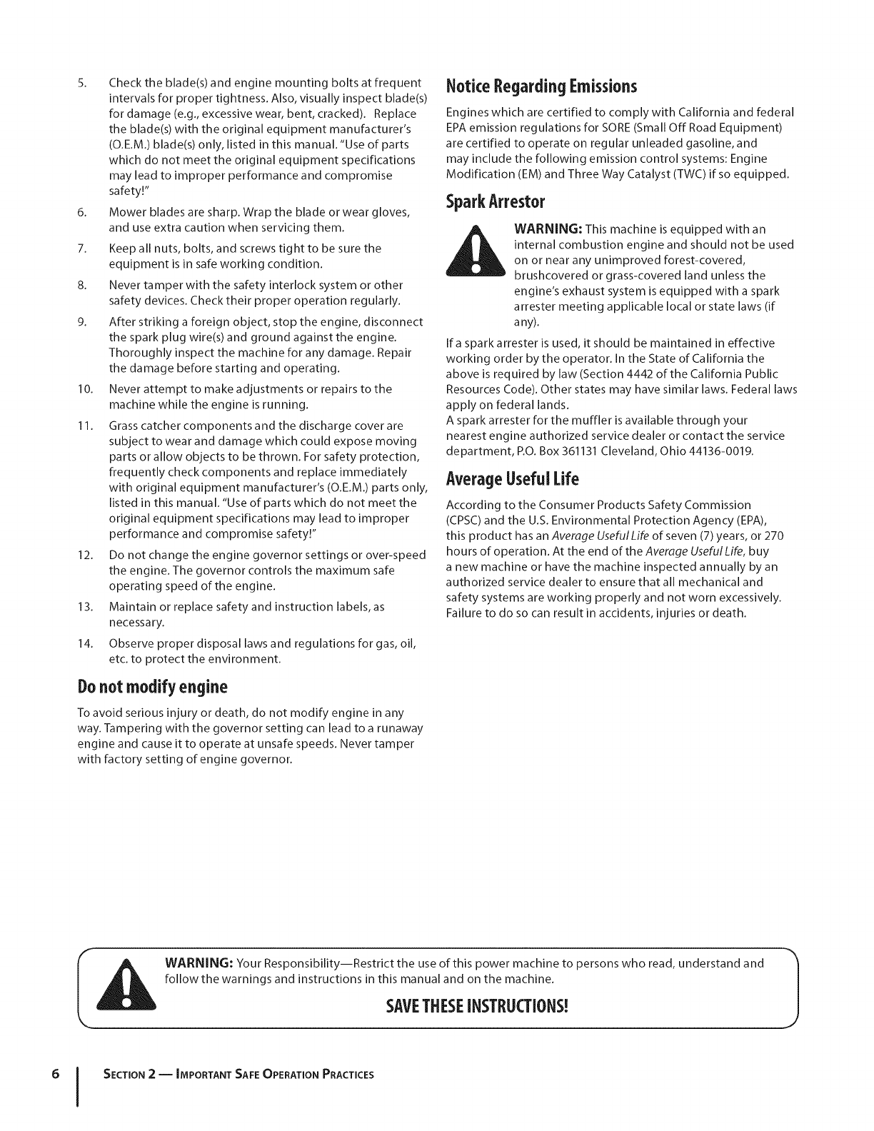
Notice Regarding Emissions
Engines which are certified to comply with California and federal
EPA emission regulations for SORE (Small Off Road Equipment)
are certified to operate on regular unleaded gasoline, and
may include the following emission control systems: Engine
Modification (EM) and Three Way Catalyst (TWC) if so equipped.
SparkArrestor
_ARNING: This machine is equipped with an
internal combustion engine and should not be used
on or near any unimproved forest-covered,
brushcovered or grass-covered land unless the
engine's exhaust system is equipped with a spark
attester meeting applicable local or state laws (if
any).
If a spark a rrester is used, it should be maintained in effective
working order by the operator. In the State of California the
above is required by law (Section 4442 of the California Public
Resources Code). Other states may have similar laws. Federal laws
apply on federal lands.
A spark attester for the muffler is available through your
nearest engine authorized service dealer or contact the service
department, P.O.Box 361131 Cleveland, Ohio 44136-0019.
AverageUsefulLife
According to the Consumer Products Safety Commission
(CPSC) and the U.S. Environmental Protection Agency (EPA),
this product has an Average Useful Life of seven (7) years, or 270
hours of operation. At the end of the Average Useful Life, buy
a new machine or have the machine inspected annually by an
authorized service dealer to ensure that all mechanical and
safety systems are working properly and not worn excessively.
Failure to do so can result in accidents, injuries or death.
WARNING: Your Responsibility--Restrict the use of this power machine to persons who read, understand and
follow the warnings and instructions in this manual and on the machine.
SAVETHESEiNSTRUCTIONS!
6I SECTION 2-- IMPORTANT SAFE OPERATION PRACTICES
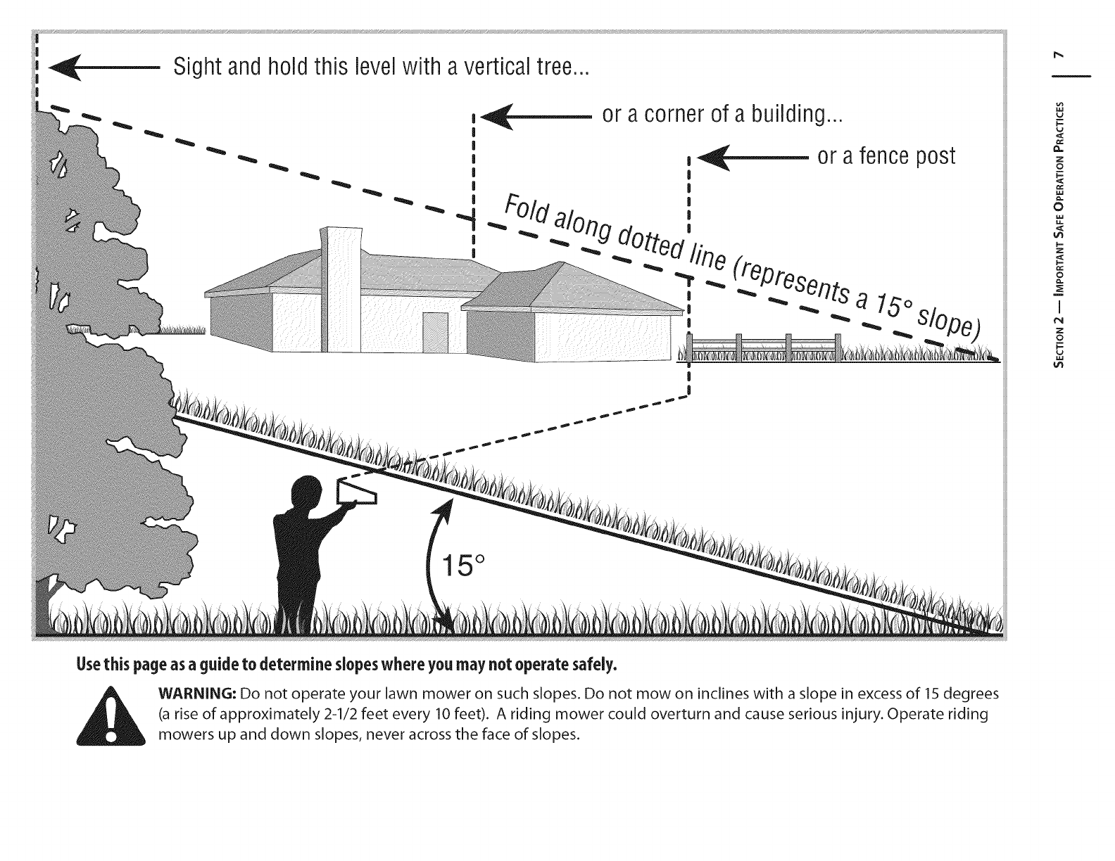
Sight and hold this levelwith a vertical tree...
I
I
|
|
|
|
|
|
or a corner of a building...
!
|
15 °
!--
Z
0
0
!--
Z
iI
¢N
Z
0
i
I-
Usethis page asaguide to determine slopeswhere you may not operate safely.
WARNING: Do not operate your lawn mower on such slopes. Do not mow on inclines with a slope in excess of 15 degrees
(a rise of approximately 2-1/2 feet every 10 feet). A riding mower could overturn and cause serious injury. Operate riding
mowers up and down slopes, never across the face of slopes.
Assembly& Set-Op 3
TractorSet-Up
NOTE:This Operators Manual covers a range of product
specifications for various models. Characteristics and features
discussed and/or illustrated in this manual may not be applicable
to all models. MTD LLC reserves the right to change product
specifications, designs and equipment without notice and
without incurring obligation.
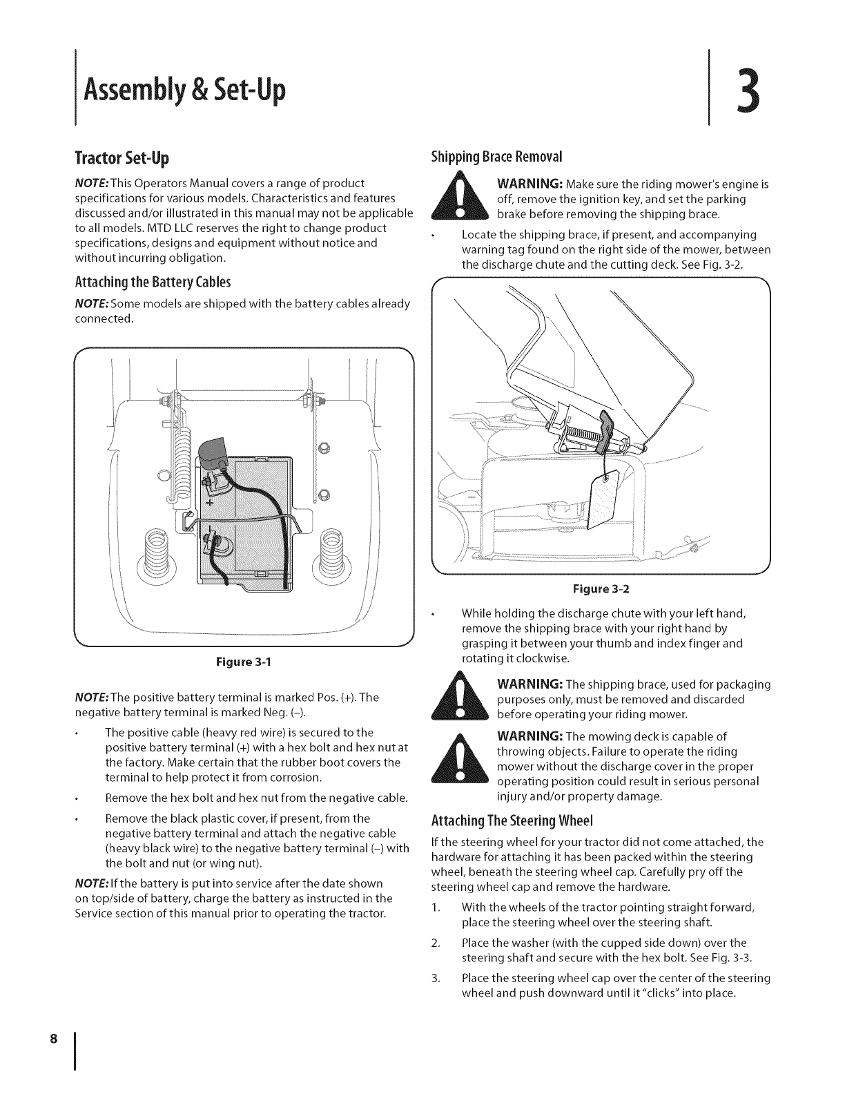
Attaching the Battery Cables
NOTE:Some models are shipped with the battery cables already
connected.
Figure 3=1
NOTE:The positive battery terminal is marked Pos. (+). The
negative battery terminal is marked Neg. (-).
The positive cable (heavy red wire)is secured to the
positive battery terminal (+) with a hex bolt and hex nut at
the factory. Make certain that the rubber boot covers the
terminal to help protect it from corrosion.
Remove the hex bolt and hex nut from the negative cable.
Remove the black plastic cover, if present, from the
negative battery terminal and attach the negative cable
(heavy black wire) to the negative battery terminal (-) with
the bolt and nut (or wing nut).
NOTE: If the battery is put into service after the date shown
on top/side of battery, charge the battery as instructed in the
Service section of this manual prior to operating the tractor.
Shipping BraceRemoval
_ ARNING: Make sure the riding mower's engine is
off, remove the ignition key, and set the parking
brake before removing the shipping brace.
Locate the shipping brace, if present, and accompanying
warning tag found on the right side of the mower, between
the discharge chute and the cutting deck. See Fig. 3-2.
Figure 3-2
While holding the discharge chute with your left hand,
remove the shipping brace with your right hand by
grasping it between your thumb and index finger and
rotating it clockwise.
_kll ARNING: The shipping brace, used for packaging
purposes only, must be removed and discarded
before operating your riding mower.
WARNING: The mowing deck is capable of
throwing objects. Failure to operate the riding
mower without the discharge cover in the proper
operating position could result in serious personal
injury and/or property damage.
Attaching TheSteering Wheel
If the steering wheel for your tractor did not come attached, the
hardware for attaching it has been packed within the steering
wheel, beneath the steering wheel cap. Carefully pry off the
steering wheel cap and remove the hardware.
1. With the wheels of the tractor pointing straight forward,
place the steering wheel over the steering shaft.
2. Place the washer (with the cupped side down) over the
steering shaft and secure with the hex bolt. See Fig. 3-3.
3. Place the steering wheel cap over the center of the steering
wheel and push downward until it "clicks" into place.
Figure 3-3
Attaching the HoodScoop(Ifsoequipped)
If the hood scoop was not secured to the hood of your tractor
at the factory, you will find it in a plastic bag, hanging from the
throttle lever.
To install:
1. Carefully pivot the tractor hood forward.
2. Remove the four screws from the underside of the hood
scoop.
3. Line up the four holes in the hood scoop with the four
holes visible through the tractor's hood Iouvres. See Fig.
3-4.
4. While holding the scoop in place, use a 3/8" socket wrench
(or box wrench) to carefully tighten the scoop onto the
hood.
Do NOT overtighten.
Figure 3-4
Attaching The Seat
Seat styles vary by tractor model and there are three different
styles available:
Standard Adjustment
Quick Adjustment
Knob Adjustment
If the seat for your tractor was not attached at the factory, refer
to Fig. 3-5, Fig. 3-6, and Fig. 3-7 to identify your tractor's seat
style and follow the applicable instructions below to attach it.
NOTE: For shipping reasons, seats are either fastened to the
tractor seat's pivot bracket with a plastic tie, or mounted
backward to the pivot bracket. In either case, free the seat
from its shipping position and remove the two hex screws (or
knobs, on models so equipped) from the bottom of seat before
proceeding with applicable instructions below.
StandardAdjustment Seat
1. Position the shoulder screws (found on the base of the seat)
inside the slot openings in the seat pivot bracket. Fig. 3-5.
2. Slide the seat slightly rearward in the seat pivot bracket,
lining up the rear slots in the pivot bracket with the
remaining two holes in the seat's base.
3. Select desired position for the seat, and secure with the
two hex screws removed earlier. See Fig. 3-5.
4. To adjust the position of the seat, loosen the two hex
screws on the bottom of the seat. Slide the seat forward or
backward as desired. Retighten the two screws.
Figure 3-5
KnobAdjustment Seat
1. Position the shoulder screws (found on the base of the
seat) inside the slot openings in the seat pivot bracket. Fig.
3-6.
2. Slide the seat slightly rearward in the seat pivot bracket,
lining up the rear slots in the pivot bracket with the
remaining two holes in the seat's base.
SECTION 2 = ASSEMBLY& SET-UP 9
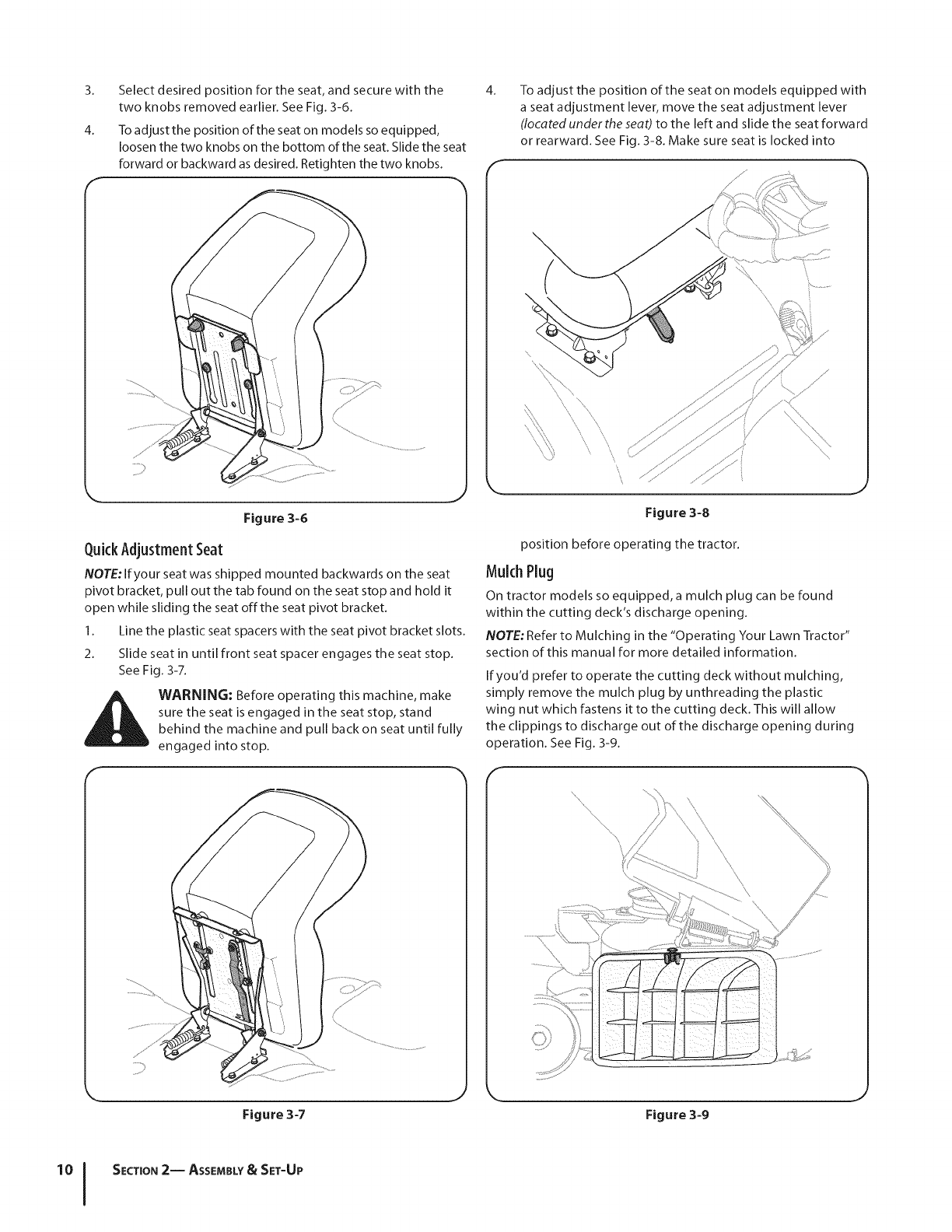
3. Select desired position for the seat, and secure with the
two knobs removed earlier. See Fig. 3-6.
4. To adjust the position of the seat on models so equipped,
loosen the two knobs on the bottom of the seat. Slide the seat
forward or backward as desired. Retighten the two knobs.
Figure 3-6
QuickAdjustmentSeat
NOTE: If your seat was shipped mounted backwards on the seat
pivot bracket, pull out the tab found on the seat stop and hold it
open while sliding the seat offthe seat pivot bracket.
1. Line the plastic seat spacers with the seat pivot bracket slots.
2. Slide seat in until front seat spacer engages the seat stop.
See Fig. 3-7.
i_ll WARNING: Before operating this machine, make
sure the seat is engaged in the seat stop, stand
behind the machine and pull back on seat until fully
engaged into stop.
Figure 3-7
4_
F
To adjust the position of the seat on models equipped with
a seat adjustment lever, move the seat adjustment lever
(located under the seat) to the left and slide the seat forward
or rearward. See Fig. 3-8. Make sure seat is locked into
\
Figure 3-8
position before operating the tractor.
Mulch Plug
On tractor models so equipped, a mulch plug can be found
within the cutting deck's discharge opening.
NOTE: Refer to Mulching in the "Operating Your Lawn Tractor"
section of this manual for more detailed information.
If you'd prefer to operate the cutting deck without mulching,
simply remove the mulch plug by unthreading the plastic
wing nut which fastens it to the cutting deck. This will allow
the clippings to discharge out of the discharge opening during
operation. See Fig. 3-9.
Figure 3-9
SECTION 2-- ASSEMBLY & SET-UP
TirePressure
/_ WARNING: Maximum tire pressure under any
circumstances is 30 psi. Equal tire pressure should be
maintained at all times.
The tires on your unit may be over-inflated for shipping
purposes. Reduce the tire pressure before operating the tractor.
Recommended operating tire pressure is approximately 10p.s.i
for the rear tires & 14p.s.i,for the front tires. Check sidewall of
tire for maximum p.s.i.
Gasand 0il Fill-up
The gasoline tank is located under the hood and has a capacity
of 1-1/2 gallons or2 gallons based on your model of tractor. Do
not overfill.
i_L WARNING: Use extreme care when handling
gasoline. Gasoline is extremely flammable and the
vapors are explosive. Never fuel machine indoors or
while the engine is hot or running. Extinguish
cigarettes, cigars, pipes, and other sources of ignition.
Service the engine with gasoline and oil as instructed in the
separate Engine Operator/Owner Manual packed with your
tractor. Read instructions carefully.
IMPORTANT:Your tractor is shipped with motor oil in the engine.
However, you MUST check the oil level before operating. Be
careful not to overfill.
MovingTheTractorManually
Your tractor's transmission is equipped with a hydrostatic relief
valve for occasions when it is necessary to move the tractor
manually. Activating this valve forces the fluid in the transmission
to bypass its normal route, allowing the rear tires to "freewheel."
To engage the hydrostatic relief valve, proceed as follows:
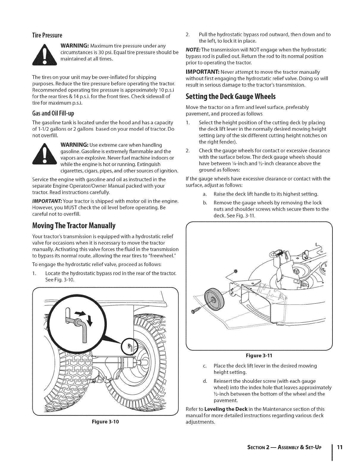
1. Locate the hydrostatic bypass rod in the rear of the tractor.
See Fig. 3-10.
Figure 3-10
2. Pull the hydrostatic bypass rod outward, then down and to
the left, to lock it in place.
NOTE:The transmission will NOT engage when the hydrostatic
bypass rod is pulled out. Return the rod to its normal position
prior to operating the tractor.
IMPORTANT: Never attempt to move the tractor manually
without first engaging the hydrostatic relief valve. Doing so will
result in serious damage to the tractor's transmission.
Setting the DeckGaugeWheels
Move the tractor on a firm and level surface, preferably
pavement, and proceed as follows
1. Select the height position of the cutting deck by placing
the deck lift lever in the normally desired mowing height
setting (any of the six different cutting height notches on
the right fender).
2. Check the gauge wheels for contact or excessive clearance
with the surface below. The deck gauge wheels should
have between 1/4-inch and 1/2-inch clearance above the
ground as follows:
If the gauge wheels have excessive clearance or contact with the
surface, adjust as follows:
a. Raise the deck lift handle to its highest setting.
b. Remove the gauge wheels by removing the lock
nuts and shoulder screws which secure them to the
deck. See Fig. 3-11.
F
Figure 3-11
c. Place the deck lift lever in the desired mowing
height setting.
d. Reinsert the shoulder screw (with each gauge
wheel) into the index hole that leaves approximately
1/2-inch between the bottom of the wheel and the
pavement.
Refer to Leveling the Deck in the Maintenance section of this
manual for more detailed instructions regarding various deck
adjustments.
SECTION 2 -- ASSEMBLY& SET-UP 11
ControlsandFeatures 4
f
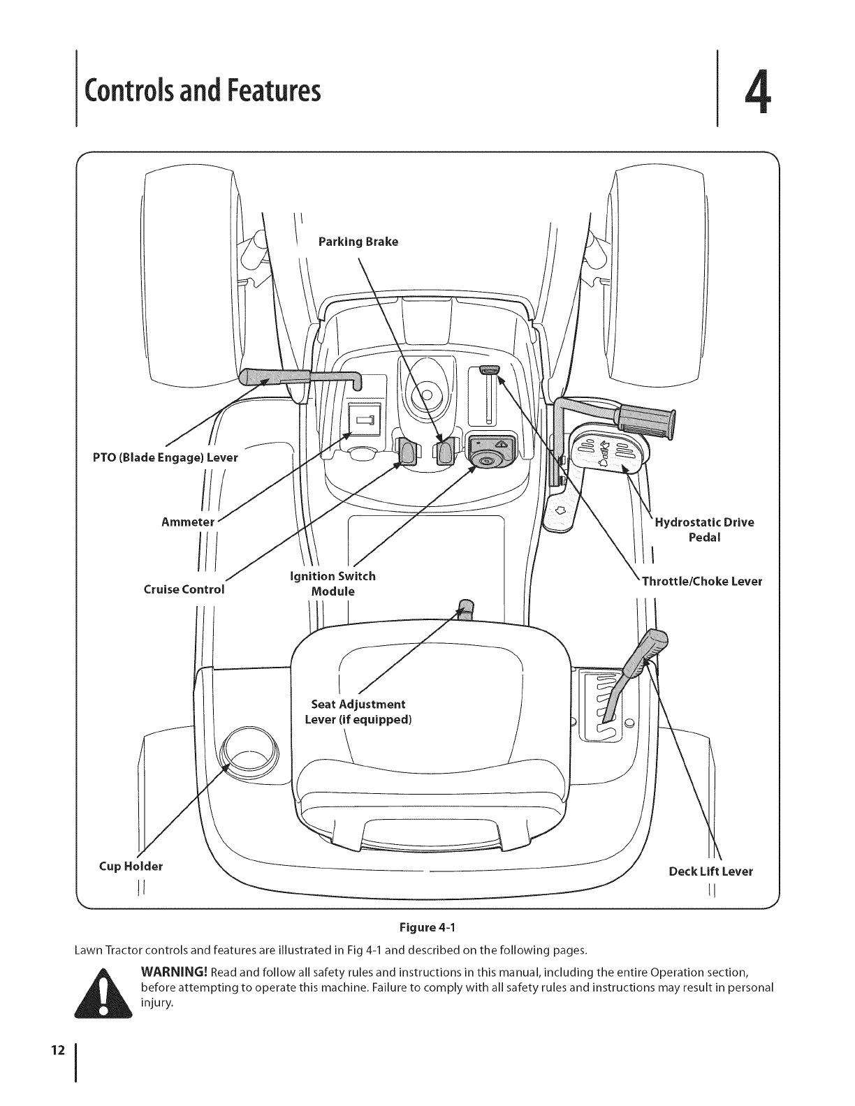
Parking Brake
PTO (Blade Engage) Lever
///
Ammeter
1//
Cruise Control ignition Switch
Module
Seat Adjustment
Lever (if equipped)
Peda I
I
throttle/Choke Lever
\
Cup Holder Deck Lift Lever
Jf _!
Figure 4=1
Lawn Tractor controls and features are illustrated in Fig 4-1 and described on the following pages.
WARNING! Read and follow all safety rules and instructions in this manual, including the entire Operation section,
before attempting to operate this machine. Failure to comply with all safety rules and instructions may result in personal
injury.
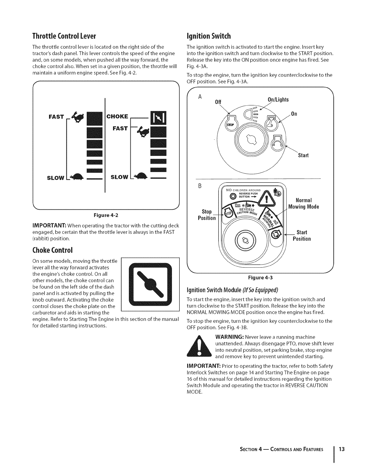
ThrottleControl Lever
The throttle control lever is located on the right side of the
tractor's dash panel. This lever controls the speed of the engine
and, on some models, when pushed all the way forward, the
choke control also. When set in a given position, the throttle will
maintain a uniform engine speed. See Fig. 4-2.
FAST
SLOW SLOW
Figure 4=2
IMPORTANT: When operating the tractor with the cutting deck
engaged, be certain that the throttle lever is always in the FAST
(rabbit) position.
ChokeControl
On some models, moving the throttle
lever all the way forward activates
the engine's choke control. On all
other models, the choke control can
be found on the left side of the dash
panel and is activated by pulling the
knob outward. Activating the choke
control closes the choke plate on the
carburetor and aids in starting the
engine. Refer to Starting The Engine in this section of the manual
for detailed starting instructions.
IgnitionSwitch
The ignition switch is activated to start the engine. Insert key
into the ignition switch and turn clockwise to the START position.
Release the key into the ON position once engine has fired. See
Fig. 4-3A.
To stop the engine, turn the ignition key counterclockwise to the
OFF position. See Fig. 4-3A.
f
AOff On/Lights
Start
Stop
©
Figure 4=3
Ignition Switch Module (IfSoEquipped)
To start the engine, insert the key into the ignition switch and
turn clockwise to the START position. Release the key into the
NORMAL MOWING MODE position once the engine has fired.
To stop the engine, turn the ignition key counterclockwise to the
OFF position. See Fig. 4-3B.
i_li WARNING: Never leave a running machine
unattended. Always disengage PTO, move shift lever
into neutral position, set parking brake, stop engine
and remove key to prevent unintended starting.
IMPORTANT: Prior to operating the tractor, refer to both Safety
Interlock Switches on page 14 and Starting The Engine on page
16 of this manual for detailed instructions regarding the Ignition
Switch Module and operating the tractor in REVERSE CAUTION
MODE.
SECTION 4 -- CONTROLS AND FEATURES 13
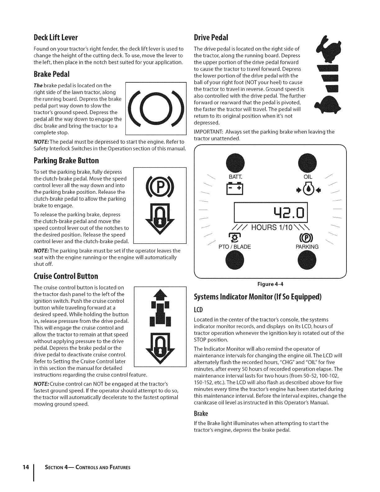
DeckLift Lever
Found on your tractor's right fender, the deck lift lever is used to
change the height of the cutting deck. To use, move the lever to
the left, then place in the notch best suited for your application.
BrakePedal
The brake pedal is located on the
right side of the lawn tractor, along
the running board. Depress the brake
pedal part way down to slow the
tractor's ground speed. Depress the
pedal all the way down to engage the
disc brake and bring the tractor to a
complete stop.
NOTE:The pedal must be depressed to start the engine. Refer to
Safety Interlock Switches in the Operation section of this manual.
ParkingBrakeButton
To set the parking brake, fully depress
the clutch-brake pedal. Move the speed _'_Ik
control lever all the way down and into tk )the parking brake position. Release the
clutch-brake pedal to allow the parking
brake to engage.
To release the parking brake, depress
the clutch-brake pedal and move the
speed control lever out of the notches to
the desired position. Release the speed
control lever and the clutch-brake pedal.
NOTE:The parking brake must be set if the operator leaves the
seat with the engine running or the engine will automatically
shut off.
CruiseControl Button
The cruise control button is located on
the tractor dash panel to the left of the
ignition switch. Push the cruise control mm
button while traveling forward at a
desired speed. While holding the button
in, release pressure from the drive pedal.
This will engage the cruise control and
allow the tractor to remain at that speed
without applying pressure to the drive
pedal. Depress the brake pedal or the
drive pedal to deactivate cruise control.
Refer to Setting the Cruise Control later
in this section the manual for detailed
instructions regarding the cruise control feature.
NOTE: Cruise control can NOT be engaged at the tractor's
fastest ground speed. If the operator should attempt to do so,
the tractor will automatically decelerate to the fastest optimal
mowing ground speed.
DrivePedal
The drive pedal is located on the right side of
the tractor, along the running board. Depress
the upper portion of the drive pedal forward
to cause the tractor to travel forward. Depress
the lower portion of the drive pedal with the
ball of your right foot (NOTyour heel) to cause
the tractor to travel in reverse. Ground speed is /
also controlled with the drive pedal. The further
forward or rearward that the pedal is pivoted,
the faster the tractor will travel. The pedal will
return to its original position when it's not
depressed.
IMPORTANT: Always set the parking brake when leaving the
tractor unattended.
J
BATT. OIL
/// HOURS 1/10\\\ --_
PTO /BLADE
q2.0
(®)
PARKING
Figure 4-4
SystemsIndicator Monitor(If SoEquipped)
LCD
Located in the center of the tractor's console, the systems
indicator monitor records, and displays on its LCD, hours of
tractor operation whenever the ignition key is rotated out of the
STOP position.
The Indicator Monitor will also remind the operator of
maintenance intervals for changing the engine oil. The LCD will
alternately flash the recorded hours, "CHG" and "OIL" for five
minutes, after every 50 hours of recorded operation elapse. The
maintenance interval lasts for two hours (from 50-52, 100-102,
150-152, etc.). The LCD will also flash as described above for five
minutes every time the tractor's engine has been started during
this maintenance interval. Before the interval expires, change the
crankcase oil level as instructed in this Operator's Manual.
Brake
If the Brake light illuminates when attempting to start the
tractor's engine, depress the brake pedal.
SECTION 4-- CONTROLS AND FEATURES
PTO(BladeEngage)
If the PTO light illuminates when attempting to start the tractor's
engine, move PTO lever into the disengaged (OFF) position.
Oil
It is normal for the Oil light to illuminate while the engine is
cranking during start-up, but if it illuminate's during operation,
while the engine is running, stop the tractor immediately and
check the crankcase oil level as instructed in this manual.
Battery
It is normal for the Battery light to illuminate while the engine is
cranking during start-up, but if it illuminate's during operation,
while the engine is running, the battery is in need of a charge
or the engine's charging system is not generating sufficient
amperage. Refer to the MAINTENANCE section of this manual
for the proper battery charging procedure or have the charging
system checked by your service dealer.
Ammeter(if SoEquipped)
On models without a Systems Indicator Monitor, an ammeter
will exist. The ammeter measures the electrical output of the
engine's charging system. Under normal operating conditions,
with engine at full throttle, the ammeter should indicate positive
charge.
ElectricPTO(BladeEngage)Knob(If SoEquipped)
To engage the power to the cutting
deck or other (separately available)
attachments on models equipped
with an electric PTO, pull outward
on the PTO (Blade Engage) knob.
Push the PTO (Blade Engage) knob
inward to disengage the power to
the cutting deck.
NOTE:The PTO (Blade Engage)
knob must be in the disengaged
(OFF) position when starting the
engine, when traveling in reverse
and if the operator leaves the seat.
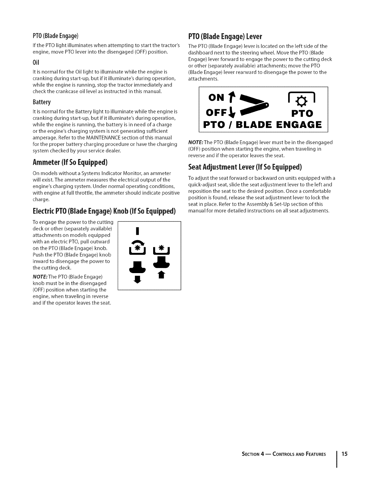
PTO(BladeEngage)Lever
The PTO (Blade Engage) lever is located on the left side of the
dashboard next to the steering wheel. Move the PTO (Blade
Engage) lever forward to engage the power to the cutting deck
or other (separately available) attachments; move the PTO
(Blade Engage) lever rearward to disengage the power to the
attachments.
ON_ l,]_!
OFF,_ PTO
PTO /BLADE ENGAGE
NOTE:The PTO (Blade Engage) lever must be in the disengaged
(OFF) position when starting the engine, when traveling in
reverse and if the operator leaves the seat.
SeatAdjustmentLever(if SoEquipped)
To adjust the seat forward or backward on units equipped with a
quick-adjust seat, slide the seat adjustment lever to the left and
reposition the seat to the desired position. Once a comfortable
position is found, release the seat adjustment lever to lock the
seat in place. Refer to the Assembly & Set-Up section of this
manual for more detailed instructions on all seat adjustments.
SECTION 4 -- CONTROLS AND FEATURES 15
Operation
TO AVOID SERIOUS INJURY
OR DEATH
•GOUP AND DOWNSLOPES,NOTACROSS.
•AVOIDSUDDENTURNS.
•DONOTOPERATETHE UNITWHERE IT COULDSLIP
ORTIP.
•IF MACHINESTOPSGOINGUPHILL,STOP BLADE(S)
AND BACKDOWNHILLSLOWLY.
•KEEPSAFETYDEVICES(GUARDS,SHIELDS,
AND SWITCHES,ETC.) IN PLACEAND WORKING.
•REMOVEOBJECTSTHATCOULDBE THROWN
BY THE BLADE(S).
• KNOWLOCATIONAND FUNCTIONOF ALL CONTROLS.
• BESUREBLADE(S)AND ENGINEARESTOPPED
BEFOREPLACINGHANDSORFEETNEARBLADE(S).
• BEFORELEAVINGOPERATOR'SPOSITION,
DISENGAGEBLADE(S), ENGAGEPARKINGBRAKE,
SHUT OFFAND REMOVEKEY.
READ OPERATOR'S
MANUAL
SafetyinterlockSwitches
J
This tractor is equipped with a safety interlock system for the
protection of the operator. If the interlock system should ever
malfunction, do not operate the tractor. Contact an authorized
MTD service dealer.
The safety interlock system prevents the engine from
cranking or starting unless the parking brake is engaged,
and the PTO (Blade Engage) knob (or lever) is in the
disengaged (OFF) position.
The engine will automatically shut off if the operator leaves
the seat before engaging the parking brake.
Modelswith Manual PTO(BladeEngage)
The engine will automatically shut off if the operator leaves
the tractor's seat with the PTO (Blade Engage) lever in the
engaged (ON) position, regardless of whether the parking
brake is engaged.
With the ignition key in the NORMAL MOWING position,
the engine will automatically shut off if the PTO (Blade
Engage) lever is moved into the engaged (ON) position
with the drive pedal in Reverse.
Modelswith ElectricPTO(BladeEngage)
The electric PTO (Blade Engage) clutch will automatically
shut off if the operator leaves the tractor's seat with the
PTO (Blade Engage) knob in the engaged (ON) position,
regardless of whether the parking brake is engaged.
With the ignition key in the NORMAL MOWING position,
the electric PTO (Blade Engage) clutch will automatically
shut off if the PTO (Blade Engage) knob is moved into
the engaged (ON) position with the drive pedal lever in
Reverse.
WARNING: Do not operate the tractor if the
interlock system is malfunctioning. This system was
designed for your safety and protection.
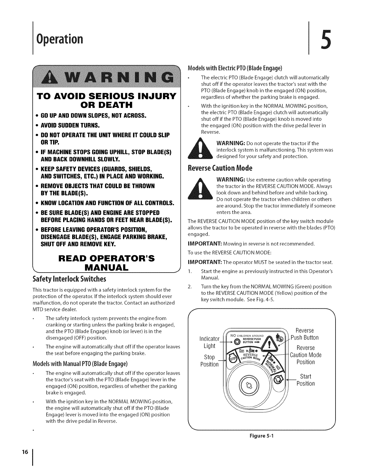
ReverseCaution Mode
WARNING: Use extreme caution while operating
the tractor in the REVERSE CAUTION MODE. Always
look down and behind before and while backing.
Do not operate the tractor when children or others
are around. Stop the tractor immediately if someone
enters the area.
The REVERSE CAUTION MODE position of the key switch module
allows the tractor to be operated in reverse with the blades (PTO)
engaged.
IMPORTANT: Mowing in reverse is not recommended.
To use the REVERSECAUTION MODE:
IMPORTANT: The operator MUST be seated in the tractor seat.
1. Start the engine as previously instructed in this Operator's
Manual.
2. Turn the key from the NORMAL MOWING (Green) position
to the REVERSECAUTION MODE (Yellow) position of the
key switch module. See Fig. 4-5.
f
Indicator
Light
Stop
Position
Reverse
Push Button
Reverse
CautionMode
Position
Start
Position
Figure 5-1
J
3.
4.
S.
6.
Depress the REVERSEPUSHBUTTON (Orange, Triangular
Button) at the top, right corner of the key switch module.
The red indicator light at the top, left corner of the key
switch module will be ON while activated. See Fig. 4-5.
Once activated (indicator light ON),the tractor can be
driven in reverse with the cutting blades (PTO)engaged.
Always look down and behind before and while backing to
make sure no children are around.
After resuming forward motion, return the key to the
NORMAL MOWING position.
IMPORTANT: The REVERSECAUTION MODE will remain
activated until:
a. The key is placed in either the NORMAL MOWING
position or STOP position.
b. The operator leaves the seat (Models with Electric
PTO 0 NLY).
The operator engages the parking brake by fully
depressing the brake pedal and holding it down
while gently pushing the parking brake button
inward (Models with Manual PTOONLY).
Engagingthe ParkingBrake.
Toengagethe parkingbrake:
1. Fully depress the brake pedal and hold it down with your
foot while gently pushing the parking brake button inward.
2. Hold the parking brake button in while removing your foot
from the brake pedal.
3. Once engaged, the parking brake button and the brake
pedal will lock in the "down" position.
Todisengagethe parking brake:
1. Slightly depress the brake pedal.
NOTE:The parking brake must be engaged if the operator leaves
the seat with the engine running or the engine will automatically
shut off.
Setting the Cutting Height
1. Select the height position of the cutting deck by placing
the deck lift lever in any of the six different cutting height
notches on the right side of the fender.
2. Adjust the deck wheels, if equipped, so that they a re
between 1/4-inch and 1/2-inch above the ground when the
tractor is on a smooth, flat surface such as a driveway.
_WARNING: Keep hands and feet away from the
discharge opening of the cutting deck.
NOTE: On models so equipped, the deck wheels a re an anti-scalp
feature of the deck and are not designed to support the weight
of the cutting deck.
Refer to Leveling the Deck in the Maintenance & Adjustments
section of this manual for more detailed instructions regarding
various deck adjustments.
Starting the Engine
WARNING: Do not operate the tractor if the
interlock system is malfunctioning. This system was
designed for your safety and protection.
NOTE: Refer to the Assembly & Set-Up section of this manual for
Gasoline and Oil fill-up instructions.
3.
4.
S.
IMPORTANT: Your tractor is shipped with motor oil in the
engine. However, you MUST check the oil level before operating.
Becareful not to overfill. Refer to the separate Engine Operator/
Owner Manual packed with your tractor. Read instructions
carefully.
1. Insert the tractor key into the ignition switch.
2. Placethe PTO (Blade Engage) lever (or knob) in the
disengaged (OFF)position.
Engage the tractor's parking brake.
Activate the choke control.
Turn the ignition key clockwise to the START position. After
the engine starts, release the key. It will return to the ON (or
Normal Mowing) position.
IMPORTANT: Do NOThold the key in the STARTposition for
longer than ten seconds at a time. Doing so may cause damage
to your engine's electric starter.
6. After the engine starts, deactivate the choke control and
place the throttle control in the FASTposition.
NOTE:Do NOT leave the choke control on while operating the
tractor. Doing so will result in a "rich" fuel mixture and cause the
engine to run poorly.
Stopping the Engine
_ ARNING: If you strike a foreign object, stop the
engine, disconnect the spark plug wire(s) and
ground against the engine. Thoroughly inspect the
machine for any damage. Repair the damage before
restarting and operating
1. If the blades are engaged, place the PTO (Blade Engage)
lever (or knob) in the disengaged (OFF) position.
2. Turn the ignition key counterclockwise to the STOP
position.
3. Remove the key from the ignition switch to prevent
unintended starting.
Driving TheTractor
WARNING: Always look down and behind before
and while traveling in reverse to avoid a back-over
accident. Avoid sudden starts, excessive speed and
sudden stops.
WARNING: Do not leave the seat of the tractor
without first placing the PTO(Blade Engage)
knob (or lever) in the disengaged (OFF) position,
depressing the brake pedal and engaging the
parking brake. If leaving the tractor unattended, also
turn the ignition key offand remove the key. Move
the throttle lever into the FAST(rabbit) position.
SECTION S -- OPERATION 17
1. Depress the brake pedal to release the parking brake and
let the pedal up.
2. Move the throttle lever into the FAST (rabbit) position.
IMPORTANT: Do NOT use the drive pedal to change the
direction of travel when the tractor is in motion. Always bring the
tractor to a complete stop before pivoting the drive pedal from
forward to reverse or vice versa.
3.
4.
To travel FORWARD, slowly depress the upper portion of
the drive pedal forward until the desired speed is achieved.
To travel in REVERSE, check that the area behind is clear
then slowly depress the lower portion of the drive pedal
with the ball of your foot (NOT your heel) until the desired
speed is achieved.
Driving OnSlopes
Refer to the SLOPE GAUGE in the Important Safe Operations
Practices section of this manual to help determine slopes where
you may operate the tractor safely.
_hll ARNING: Do not mow on inclines with a slope in
excess of 15 degrees (a rise of approximately 2-1/2
feet every 10 feet). The tractor could overturn and
cause serious injury.
Mow up and down slopes, NEVER across.
Exercise extreme caution when changing direction on
slopes.
Watch for holes, ruts, bumps, rocks, or other hidden
objects. Uneven terrain could overturn the machine. Tall
grass can hide obstacles.
Avoid turns when driving on a slope, lfa turn must be
made, turn down the slope. Turning up a slope greatly
increases the chance of a roll over.
Avoid stopping when driving up a slope. If it is necessary
to stop while driving up a slope, start up smoothly and
carefully to reduce the possibility of flipping the tractor
over backward.
SettingTheCruiseControl
NOTE:The cruise control feature should only be utilized while
traveling in the forward direction.
Slowly press the upper portion of the drive pedal until the
desired speed is achieved.
Lightly press the cruise control lever.
While continuing to hold the cruise lever down, lift your
foot from the drive pedal (you should feel the cruise latch
engage).
Once engaged, the cruise control lever and the drive
pedal will lock in the "down" position, and the tractor will
maintain the same forward speed.
NOTE: Cruise control can not be engaged at the tractor's
fastest ground speed. If the operator should attempt to do so,
the tractor will automatically decelerate to the fastest optimal
mowing ground speed.
Disengage the cruise control using one of the following
methods:
1. Depress the brake pedal to disengage the cruise control
and stop the tractor.
2. Lightly depress the drive pedal.
To change the direction of travel to reverse when operating with
cruise control, depress the brake pedal to disengage the cruise
control and bring the tractor to a complete stop. Then slowly
depress the rear portion of the drive pedal with the ball of your
foot to travel in reverse.
Engagingthe Blades
Engaging the PTO (Blade Engage) transfers power to the cutting
deck or other (separately available) attachments. To engage the
blades, proceed as follows:
1. Move the throttle control lever to the FAST (ra bbit)
position.
Modelswith Manual PT0
2. a. Grasp the PTO (Blade Engage) lever and pivot it all the
way forward into the engaged (ON) position.
Modelswith ElectricPT0
3.
b. Pull the PTO (Blade Engage) knob outward into the
engaged (ON) position.
Keep the throttle lever in the FAST (rabbit) position for the
most efficient use of the cutting deck or other (separately
available) attachments
IMPORTANT: The engine (on models with a manual PTO)
or electric PTOclutch (on models with an electric PTO)will
automatically shut off if the PTOis engaged with the drive pedal
in position for reverse travel with the ignition key in the NORMAL
MOWING position. Refer to Safety Interlock Switches earlier in
this section.
Usingthe DeckLift Lever
To raise the cutting deck, move the deck lift lever to the left, then
place it in the notch best suited for your application. Refer to
Setting The Cutting Height earlier in this section.
Mowing
ll_ WARNING: To help avoid blade contact or a
thrown object injury, keep bystanders, helpers,
children and pets at least 75 feet from the machine
while it is in operation. Stop machine if anyone
enters the area.
The following information will be helpful when using the cutting
deck with your tractor:
WARNING: Plan your mowing pattern to avoid
discharge of materials toward roads, sidewalks,
bystanders and the like. Also, avoid discharging
material against a wall or obstruction which may
cause discharged material to ricochet back toward
the operator.
Do not mowat high ground speed, especially if a mulch kit
or grass collector is installed.
For best results it is recommended that the first two laps be
cut with the discharge thrown towards the center. After the
SECTION S-- OPERATION
first two laps, reverse the direction to throw the discharge
to the outside for the balance of cutting. This will give a
better appearance to the lawn.
Do not cut the grass too short. Short grass invites weed
growth and yellows quickly in dry weather.
Mowing should always be done with the engine at full
throttle.
Under heavier conditions it may be necessary to go back
over the cut area a second time to geta clean cut.
Do NOT attempt to mow heavy brush and weeds and
extremely tall grass. Your tractor is designed to mow lawns,
NOT clear brush.
Keep the blades sharp and replace the blades when
worn. Refer to Cutting Blades in the Service section of this
manual for proper blade sharpening instructions.
Headlights
On some models, the lamps are ON whenever the tractor's
engine is running. On other models, the lamps are ON
whenever the ignition key is moved out of the STOPposition.
On all models, the lamps turn OFFwhen the ignition key is
moved to the STOPposition.
NOTE:On models using the four-position key switch, the
headlights will be activated when the key is moved into the Run/
Lights position. See Fig. 4-3A in the Controls & Features section
for an illustration of the lights-on position on all four-position
key switch models.
Mulching(If soequipped)
Select models come equipped with a mulch kit which
incorporates special blades, already standard on the tractor, in a
process of recirculating grass clippings repeatedly beneath the
cutting deck. The ultra-fine clippings are then forced back into
the lawn where they act as a natural fertilizer.
Observe the following points for the best results when mulching:
Never attempt to mulch if the lawn is damp. Wet grass
tends to stick to the underside of the cutting deck
preventing proper mulching of the clippings.
Do NOT attempt to mulch more than 1/3 the total height of
the grass or approximately 1-1/2 inches. Doing so will cause
the clippings to clump up beneath the deck and not be
mulched effectively.
Maintain a slow ground speed to allow the grass clippings
more time to effectively be mulched.
Always position the throttle control lever in the FAST
(rabbit) position and allow it to remain there while
mowing. Failing to keep the engine at full throttle places
strain on the tractor's engine and does not allow the blades
to properly mulch grass.
NOTE: It is not necessary to remove the discharge chute to
operate the mower with the mulch kit installed.
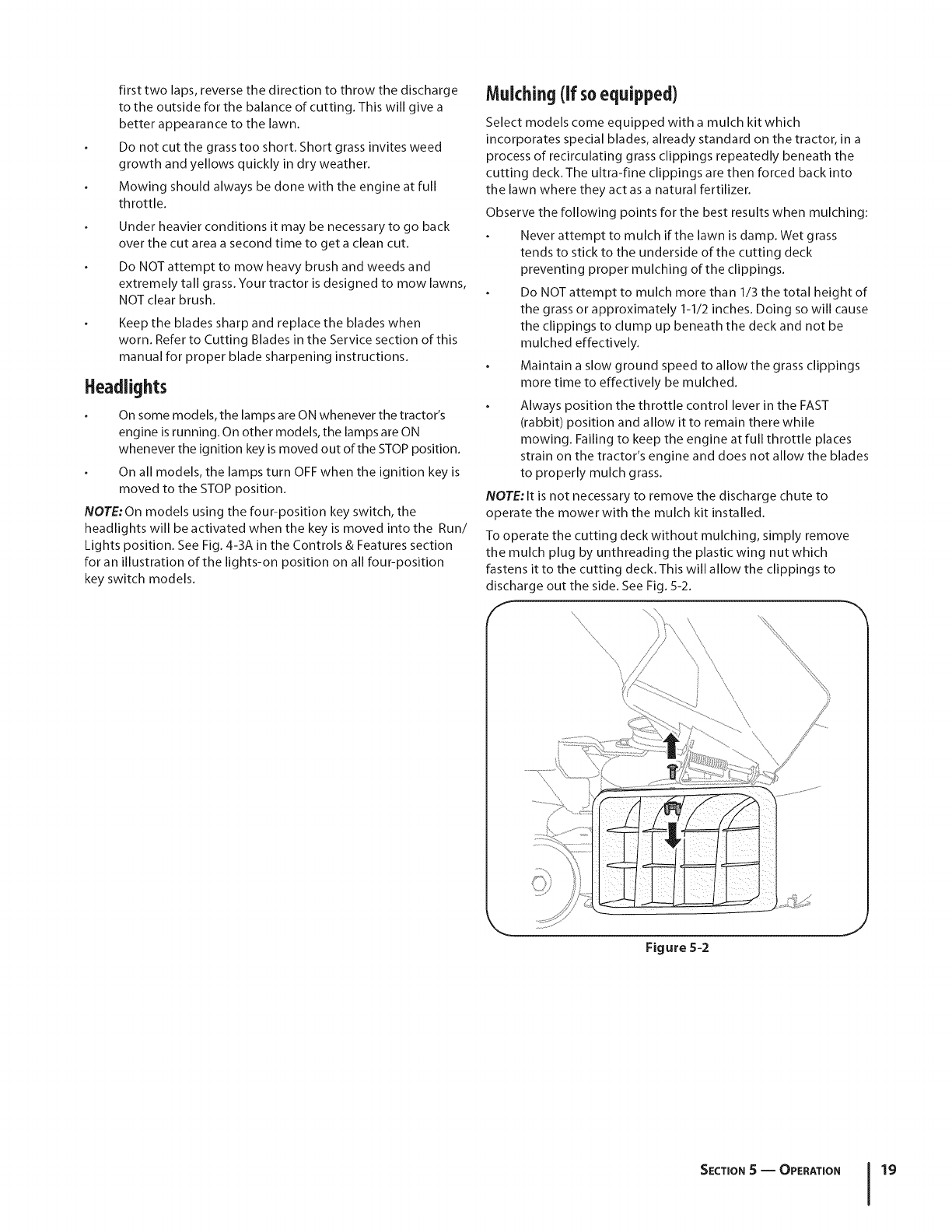
To operate the cutting deck without mulching, simply remove
the mulch plug by unthreading the plastic wing nut which
fastens it to the cutting deck. This will allow the clippings to
discharge out the side. See Fig. 5-2.
f\
\\ \
'\\
Figure 5-2
J
SECTION S -- OPERATION 19
Maintenance& Adjustments
Maintenance
WARNING: Before performing any maintenance or
repairs, disengage PTO, move shift lever into neutral
position, set parking brake, stop engine and remove
key to prevent unintended starting.
Refer to the Engine Operator/Owner Manual for engine
maintenance instructions.
Check engine oil level before each use as instructed in the
Engine Operator/Owner Manual packed with your unit. Follow
the instructions carefully.
ChangingEngine0il
WARNING! If the engine has been recently run, the
engine, muffler and surrounding metal surfaces will
be hot and can cause burns to the skin. Exercise
caution to avoid burns.
NOTE:The oil filter should be changed at every oil change
interval. To complete an oil change, proceed as follows:
1. Run the engine for a few minutes to allow the oil in the
crankcase to warm up. Warm oil will flow more freely and
carry away more of the engine sediment which may have
settled at the bottom of the crankcase. Use care to avoid
burns from hot oil.
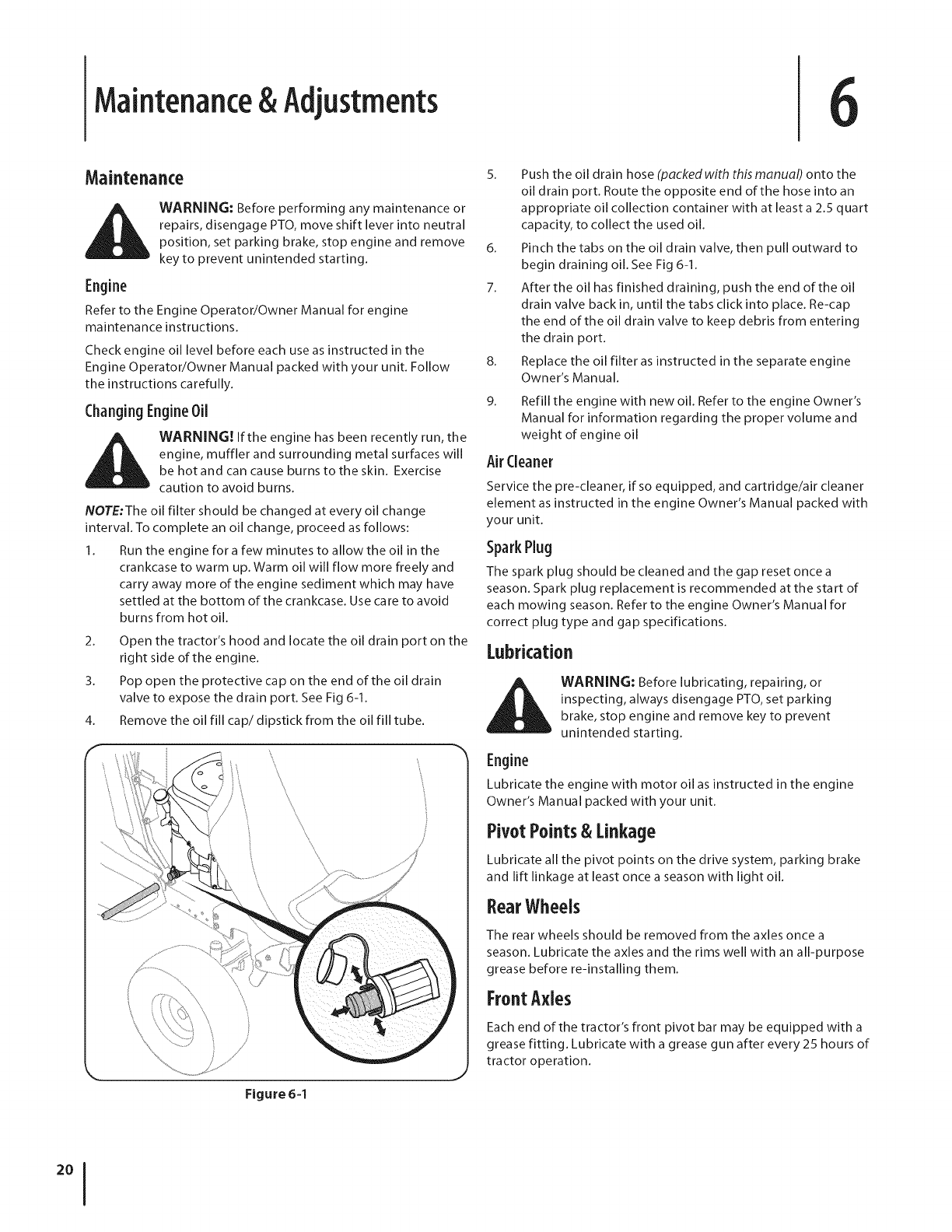
2. Open the tractor's hood and locate the oil drain port on the
right side of the engine.
3. Pop open the protective cap on the end of the oil drain
valve to expose the drain port. See Fig 6-1.
4. Remove the oil fill cap/dipstick from the oil fill tube.
Figure 6-1
8,
9,
5. Push the oil drain hose (packed with this manual) onto the
oil drain port. Route the opposite end of the hose into an
appropriate oil collection container with at least a 2.5 quart
capacity, to collect the used oil.
6. Pinch the tabs on the oil drain valve, then pull outward to
begin draining oil. See Fig 6-1.
7. After the oil has finished draining, push the end of the oil
drain valve back in, until the tabs click into place. Re-cap
the end of the oil drain valve to keep debris from entering
the drain port.
Replace the oil filter as instructed in the separate engine
Owner's Manual.
Refill the engine with new oil. Refer to the engine Owner's
Manual for information regarding the proper volume and
weight of engine oil
AirCleaner
Service the pre-cleaner, if so equipped, and cartridge/air cleaner
element as instructed in the engine Owner's Manual packed with
your unit.
Spark Plug
The spark plug should be cleaned and the gap reset oncea
season. Spark plug replacement is recommended at the start of
each mowing season. Refer to the engine Owner's Manual for
correct plug type and gap specifications.
Lubrication
il_il_ll_ll WARNING: Before lubricating, repairing, or
inspecting, always disengage PTO, set parking
brake, stop engine and remove key to prevent
unintended starting.
Engine
Lubricate the engine with motor oil as instructed in the engine
Owner's Manual packed with your unit.
PivotPoints & Linkage
Lubricate all the pivot points on the drive system, parking brake
and lift linkage at least once a season with light oil.
RearWheels
The rear wheels should be removed from the axles once a
season. Lubricate the axles and the rims well with an all-purpose
grease before re-installing them.
FrontAxles
Each end of the tractor's front pivot bar may be equipped with a
grease fitting. Lubricate with a grease gun after every 25 hours of
tractor operation.
Cleaningthe EngineAndDeck
Any fuel or oil spilled on the machine should be wiped off
promptly. Do NOT allow debris to accumulate around the cooling
fins of the engine or on any other part of the machine.
IMPORTANT: The use of a pressure washer to clean your
tractor is NOT recommended. It may cause damage to electrical
components, spindles, pulleys, bearings or the engine.
The battery is sealed and is maintenance-free. Acid levels cannot
be checked.
Always keep the battery cables and terminals clean and
free of corrosive build-up.
After cleaning the battery and terminals, apply a light coat
of petroleum jelly or grease to both terminals.
Always keep the rubber boot positioned over the positive
terminal to prevent shorting.
IMPORTANT: If removing the battery for any reason,
disconnect the NEGATIVE(Black)wire from it's terminal first,
followed by the POSITIVE(Red)wire. When re-installing the
battery, always connect the POSITIVE(Red)wire its terminal
first, followed by the NEGATIVE(Black) wire. Be certain that the
wires are connected to the correct terminals; reversing them
could change the polarity and result in damage to your engine's
alternating system.
(:leaning Battery
Clean the battery by removing it from the tractor and washing
with a baking soda and water solution. If necessary, scrape the
battery terminals with a wire brush to remove deposits. Coat
terminals and exposed wiring with grease or petroleum jelly to
prevent corrosion.
Battery Failures
Some common causes for battery failure are:
Incorrect initial activation
Overcharging
Freezing
Undercharging
Corroded connections
These failures are NOT covered by your tractor's warranty.
DeckWashSystemTM
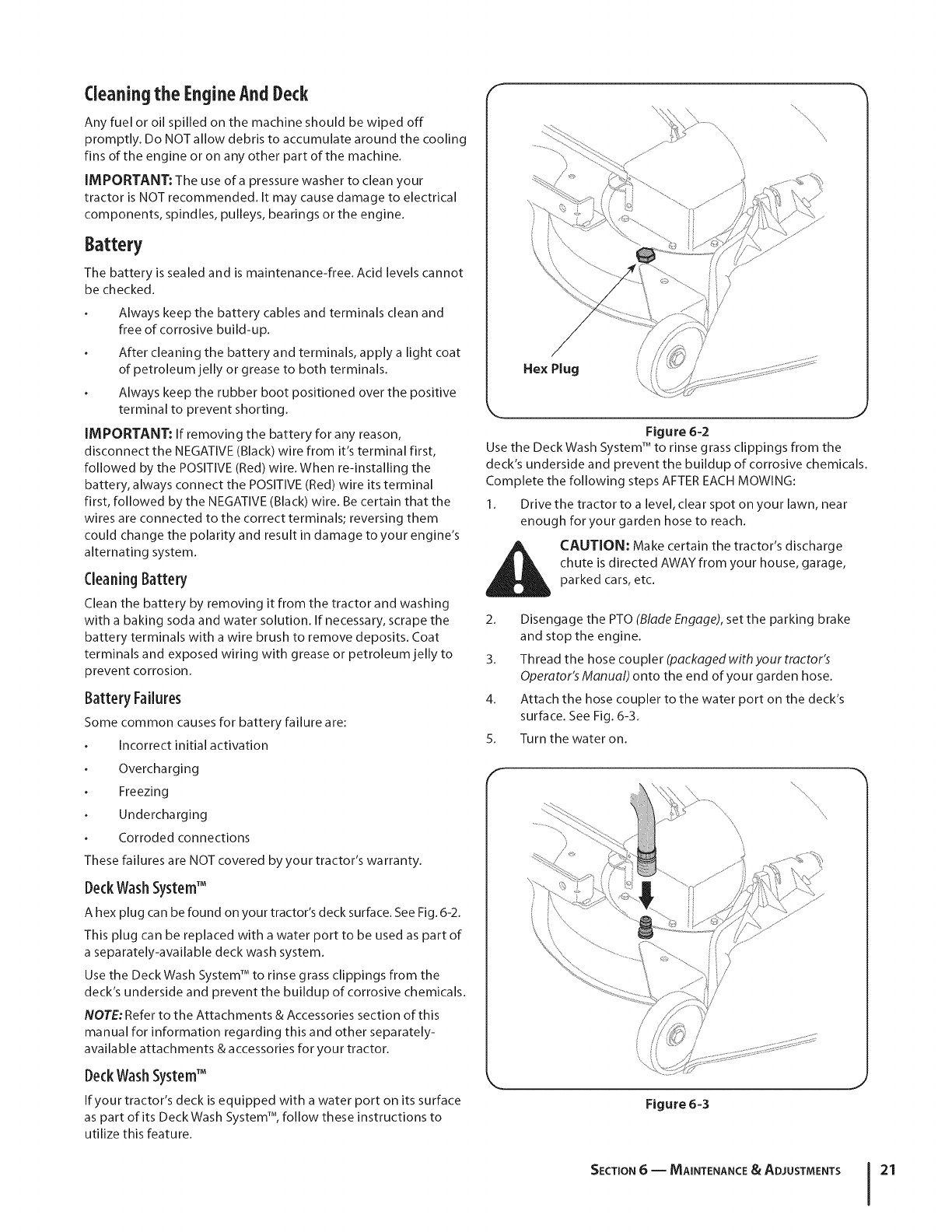
A hex plug can be found on your tractor's deck surface. See Fig. 6-2.
This plug can be replaced with a water port to be used as part of
a separately-available deck wash system.
Use the Deck Wash System TM to rinse grass clippings from the
deck's underside and prevent the buildup of corrosive chemicals.
NOTE: Refer to the Attachments & Accessories section of this
manual for information regarding this and other separately-
available attachments & accessories for your tractor.
DeckWashSystemTM
If your tractor's deck is equipped with a water port on its surface
as part of its Deck Wash System TM, follow these instructions to
utilize this feature.
F
/
Hex Plug
\
M J
Figure 6=2
Use the Deck Wash SystemTM to rinse grass clippings from the
deck's underside and prevent the buildup of corrosive chemicals.
Complete the following steps AFTEREACHMOWING:
1. Drive the tractor to a level, clear spot on your lawn, near
enough for your garden hose to reach.
CAUTION: Make certain the tractor's discharge
chute is directed AWAYfrom your house, garage,
parked cars, etc.
2. Disengage the PTO (Blade Engage), set the parking brake
and stop the engine.
3. Thread the hose coupler (packagedwithyourtractor's
Operator's Manual) onto the end of your garden hose.
4. Attach the hose coupler to the water port on the deck's
surface. See Fig. 6-3.
5. Turn the water on.
F
Figure 6-3
SECTION 6 -- MAINTENANCE & ADJUSTMENTS 21
6. While sitting in the operator's position on the tractor, start
the engine and place the throttle lever in the FAST (rabbit)
position.
7. Move the tractor's PTO (Blade Engage) into the ON position.
8. Remain in the operator's position with the cutting deck
engaged for a minimum of two minutes, allowing the
underside of the cutting deck to thoroughly rinse.
9. Move the tractor's PTO (Blade Engage) into the OFF
position.
10. Turn the ignition key to the STOP position to turn the
tractor's engine offl
11. Turn the water off and detach the hose coupler from the
water port on your deck's surface.
12. On 46"decks, repeat steps 4through 11 on the opposite
side of the cutting deck.
IMPORTANT: After cleaning your deck with the Deck Wash
SystemTM ,return to the operator's position and engage the PTO.
Keep the cutting deck running for a minimum of two minutes,
allowing the underside of the cutting deck to thoroughly dry.
Adjustments
WARNING: Never attempt to make any
adjustments while the engine is running, except
where specified in the operator's manual.
Levelingthe Deck
NOTE.: Check the tractor's tire pressure before performing
any deck leveling adjustments. Refer to Tires on page 23 for
information regarding tire pressure.
Front ToRear
The front of the cutting deck is supported by a stabilizer bar that
can be adjusted to level the deck from front to rear. The front of
the deck should be between 1/4-inch and 3/8-inch lower than
the rear of the deck. Adjust if necessary as follows:
1. With the tractor parked on a firm, level surface, place the
deck lift lever in the top notch (highest position) and rotate
the blade nearest the discharge chute so that it is parallel
with the tractor.
2. Measure the distance from the front of the blade tip to
the ground and the rear of the blade tip to the ground.
The first measurement taken should be between 1/4" and
3/8" less than the second measurement. Determine the
approximate distance necessary for proper adjustment and
proceed, if necessary, to the next step.
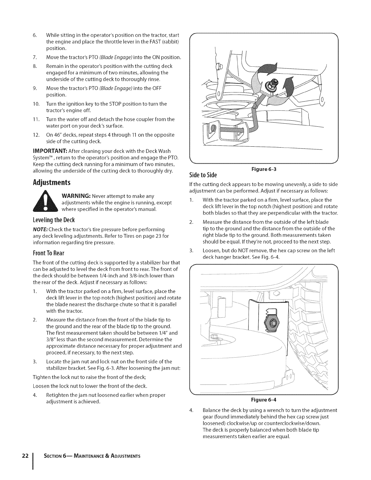
3. Locate the jam nut and lock nut on the front side of the
stabilizer bracket. See Fig. 6-3. After loosening the jam nut:
Tig hten the lock nut to raise the front of the deck;
Loosen the lock nut to lower the front of the deck.
4. Retighten the jam nut loosened earlier when proper
adjustment is achieved.
J
Figure 6-3
Sideto Side
If the cutting deck appears to be mowing unevenly, a side to side
adjustment can be performed. Adjust if necessary as follows:
1. With the tractor parked on a firm, level surface, place the
deck lift lever in the top notch (highest position) and rotate
both blades so that they are perpendicular with the tractor.
2. Measure the distance from the outside of the left blade
tip to the ground and the distance from the outside of the
right blade tip to the ground. Both measurements taken
should be equal. If they're not, proceed to the next step.
Loosen, but do NOT remove, the hex cap screw on the left
deck hanger bracket. See Fig. 6-4.
3.
f/
4. Balance the deck by using a wrench to turn the adjustment
gear (found immediately behind the hex cap screw just
loosened) clockwise/up or counterclockwise/down.
The deck is properly balanced when both blade tip
measurements taken earlier are equal.
SECTION 6-- MAINTENANCE &ADJUSTMENTS
5. Retighten the hex cap screw on the left deck hanger
bracket when proper adjustment is achieved.
SeatAdjustment
Refer to the Assembly & Set-Up section of this manual for seat
adjustment instructions.
Parking BrakeAdjustment
WARNING: Never attempt to adjust the brakes
while the engine is running. Always disengage PTO,
move shift lever into neutral position, stop engine
and remove key to prevent unintended starting.
If the tractor does not come to a complete stop when the brake
pedal is completely depressed, or if the tractor's rear wheels
can roll with the parking brake applied, the brake is in need of
adjustment. See an authorized MTD Service Dealer to have your
brakes properly adjusted.
MaintenanceSchedule
Before
Eachuse Every
10Hours Every
25Hours Every
50Hours Every
100Hours
CleanHood/DashLouvers V '/
CheckEngine0il Level _
CheckAirFilter for Dirty,LooseorDamagedParts
CleanandRe-oilAir Filter'sFoamPredeaner
ReplaceAir Filter Element _"
ChangeEngine0il and Replace0il Filter _"
CleanBattery Terminals V/V/
LubeFrontAxlesand Rims _/ _/
CleanEngineCoolingFins V /V/
Lube FrontDeckWheels(ifequipped) Vf Vf
LubeDeckSpindles V /V/
LubePedalPivotPoints V /V/
CheckSparkPlugCondition& Gap V /V/
ReplaceFuelFilter V /
Prior
to Storing
,/
NOTE:This Operators Manual covers a range of product specifications for various models. Characteristics and features discussed and/
or illustrated in this manual may not be applicable to all models. MTD LLC reserves the right to change product specifications, designs
and equipment without notice and without incurring obligation.
IMPORTANT: Since this manual covers a range of various tractor models, it is important to consult the specific engine operator's
manual included with this machine for detailed engine maintenance procedures and intervals.
SECTION 6-- MAINTENANCE & ADJUSTMENTS 23
Service 7
CuttingDeckRemoval
NOTE:Models equipped with a 38-inch deck have one deck idler
pulley. Models equipped with a 42- and 46-inch deck have two
deck idler pulleys.
To remove the cutting deck, proceed as follows:
1. Place the PTO (Blade Engage) lever in the disengaged (OFF)
position and engage the parking brake.
2. Lower the deck by moving the deck lift lever into the
bottom notch on the right fender.
3. Remove the belt-keeper rod, from around the tractor's
engine pulley, by removing the self-tapping screw (A) that
secures it. See Fig. 7-1.
Note: Make a mental note what hole the other end of the belt-
keeper rod is inserted in for reinstallation purposes.
/
Figure 74
4. Remove the belt (C) from around the tractor's engine
pulley. See Fig. 7-1.
5. Looking at the cutting deck from the left side of the tractor,
locate the cotter pin that secures the deck support rod
on the rear left side of the deck. See Fig. 7-2. Remove the
cotter pin that secures the deck support rod, and carefully
remove the deck support from the deck lift arm.
6. Repeat the above steps on the tractor's right side.
NOTE:The deck support rod on the right side of the tractor is
secured using hair pin clip as opposed to a cotter pin, which you
might had noticed was used on the left side. This is normal and
should be reinstalled in the same manner as removed.
7. Move the deck lift lever into the top notch on the right
fender to raise the deck lift arms up and out of the way.
8. Gently slide the cutting deck toward the front of the tractor
carefully guiding the hooks on the deck off of the deck
stabilizer rod.
9_
Figure 7=2
Carefully remove the PTO cable from the rear of the
cutting deck by removing the hair pin clip which secures it.
Remove the spring from the deck idler bracket. See Fig. 7-3
F
Figure 7-3
10. Gently slide the cutting deck (from the leftside) out from
underneath the tractor.
Tires
_ WARNING! Never exceed the maximum inflation
pressure shown on the sidewall of tire.
The recommended operating tire pressure is:
Approximately 10 psi for the rear tires
Approximately 14 psi for the front tires
IMPORTANT: Refer to the tire sidewall for exact tire
manufacturer's recommended or maximum psi. Do not
overinflate. Uneven tire pressure could cause the cutting deck to
mow unevenly.
CALIFORNIA PROPOSITION 65 WARNING!
Battery posts, terminals, and related accessories
contain lead and lead compounds, chemicals known
to the State of California to cause cancer and
reproductive harm. Wash hands after handling.
CAUTION: If removing the battery, disconnect the
NEGATIVE (Black) wire from it's terminal first,
followed by the POSITIVE (Red) wire. When re-
installing the battery, always connect the POSITIVE
(Red) wire its terminal first, followed by the
NEGATIVE (Black) wire.
JumpStarting
i_ WARNING! Never jump start a damaged or frozen
battery. Be certain the vehicles do not touch, and
ignitions are off. Do not allow cable clamps to touch.
1. Connect positive (+) cable to positive post (+) of your
tractor's discharged battery.
2. Connect the other end of the cable to the (positive +) post
of the jumper battery.
3. Connect the second cable (negative -) to the other post of
the jumper battery.
4. Make the final connection on the engine block of the
tractor, away from the battery. Attach to a unpainted part
to assure a good connection.
CAUTION: If the jumper battery is installed on a
vehicle (i.e. car, truck), do NOT start the vehicle's
engine when jump starting your tractor.
5. Start the tractor (as instructed in the Operation section of
this manual).
6. Set the tractor's parking brake before removing the jumper
cables, in reverse order of connection.
Charging
AWARNING! Batteries give off an explosive gas
while charging. Charge the battery in a well
ventilated area and keep away from an open flame
or pilot light as on a water heater, space heater,
furnace, clothes dryer or other gas appliances.
CAUTION: When charging your tractor's battery,
use only a charger designed for 12V lead-acid
batteries. Read your battery charger's Owner's
Manual prior to charging your tractor's battery.
Always follow its instructions and heed its warnings.
If your tractor has not been put into use for an extended period
of time, charge the battery as follows:
1. Set your battery charger to deliver a max of 10 amperes.
If your battery charger is automatic, charge the battery until the
charger indicates that charging is complete. If the charger is not
automatic, charge for no fewer than eight hours.
Fuse
One 20 AMP fuse is installed in your tractor's wiring harness to
protect the tractor's electrical system from damage caused by
excessive amperage.
If the electrical system does not function, or your tractor's engine
will not crank, first check to be certain that the fuse has not
blown. It can be found at the rear of the unit, underneath the
fender located by the battery.
_ ARNING! Always use a fuse with the same
amperage capacity for replacement.
SECTION7 -- SERVICE 25
Cutting Blades
WARNING! Shut the engine off and remove
ignition key before removing the cutting blade(s) for
sharpening or replacement. Protect your hands by
using heavy gloves when grasping the blade.
WARNING! Periodically inspect the blade and/or
spindle for cracks or damage, especially after you've
struck a foreign object. Do not operate the machine
until damaged components are replaced.
To remove the blades, proceed as follows.
1+ Remove the deck from beneath the tractor, (refer to
Cutting Deck Removal earlier in this section) then gently
flip the deck over to expose its underside.
2+ Place a block of wood between the center deck housing
baffle and the cutting blade to act as a stabilizer.
See Fig+ 7-4+
3+ Remove the hex flange nut that secures the blade to the
spindle assembly. See Fig. 7-4.
Figure 7-4
Figure 7-5
CAUTION: If the cutting edge of the blade has
previously been sharpened, or if any metal
separation is present, replace the blades with new
ones.
WARNING! A poorly balanced blade will cause
excessive vibration, may damage to the tractor and/
or result in personal injury.
5+ Test the blade's balance using a blade balancer. Grind
metal from the heavy side until it balances evenly.
NOTE:When replacing the blade, be sure to install the blade with
the side of the blade marked "Bottom" (or with a part number
stamped in it) facing the ground when the mower is in the
operating position.
CAUTION: Use a torque wrench to tighten the
blade spindle hex flange nut to between 70 Ibs-ft
and 90 Ibs-ft.
4. To properly sharpen the cutting blades, remove equal
amounts of metal from both ends of the blades along the
cutting edges, parallel to the trailing edge, ata 25 °- to 30 °
angle. Always grind each cutting blade edge equally to
maintain proper blade balance. See Fig+ 7-5+
SECTION7-- SERVICE
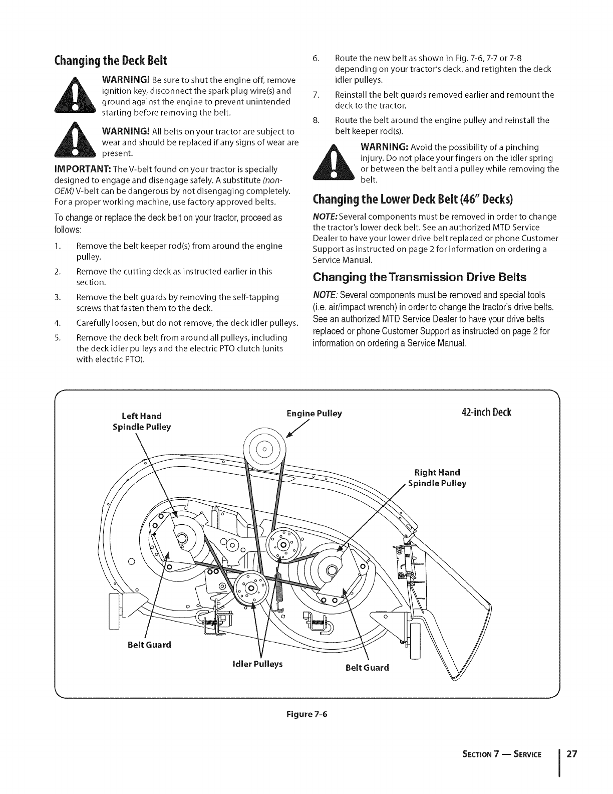
(::hangingthe DeckBelt 6_
WARNING! Be sure to shut the engine off, remove
ignition key, disconnect the spark plug wire(s) and 7.
ground against the engine to prevent unintended
starting before removing the belt. 8.
WARNING! All belts on your tractor are subject to
wear and should be replaced if any signs of wear are
present.
IMPORTANT: The V-belt found on your tractor is specially
designed to engage and disengage safely. A substitute (non-
OEM) V-belt can be dangerous by not disengaging completely.
For a proper working machine, use factory approved belts.
Tochangeor replacethe deckbelt onyourtractor,proceedas
follows:
Remove the belt keeper rod(s) from around the engine
pulley.
Remove the cutting deck as instructed earlier in this
section.
Remove the belt guards by removing the self-tapping
screws that fasten them to the deck.
Carefully loosen, but do not remove, the deck idler pulleys.
Remove the deck belt from around all pulleys, including
the deck idler pulleys and the electric PTO clutch (units
with electric PTO).
2.
3.
4.
5.
Route the new belt as shown in Fig. 7-6, 7-7 or 7-8
depending on your tractor's deck, and retighten the deck
idler pulleys.
Reinstall the belt guards removed earlier and remount the
deck to the tractor.
Route the belt around the engine pulley and reinstall the
belt keeper rod(s).
_WARNING: Avoid the possibility of a pinching
injury. Do not place your fingers on the idler spring
or between the belt and a pulley while removing the
belt.
(:hanging the lower DeckBelt (46"Decks)
NOTE: Several components must be removed in order to change
the tractor's lower deck belt. See an authorized MTD Service
Dealer to have your lower drive belt replaced or phone Customer
Support as instructed on page 2 for information on ordering a
Service Manual.
Changing the Transmission Drive Belts
NOTE:Severalcomponentsmust beremovedandspecialtools
(i.e.air/impactwrench)in orderto changethe tractor'sdrive belts.
SeeanauthorizedMTDServiceDealerto haveyourdrivebelts
replacedor phoneCustomerSupportas instructedon page2for
informationonorderinga ServiceManual.
Left Hand
Spindle Pulley
42-inch Deck
Right Hand
Spindle Pulley
Belt Guard
Idler Pulleys Belt Guard
Figure 7-6
SECTION7 -- SERVICE 27
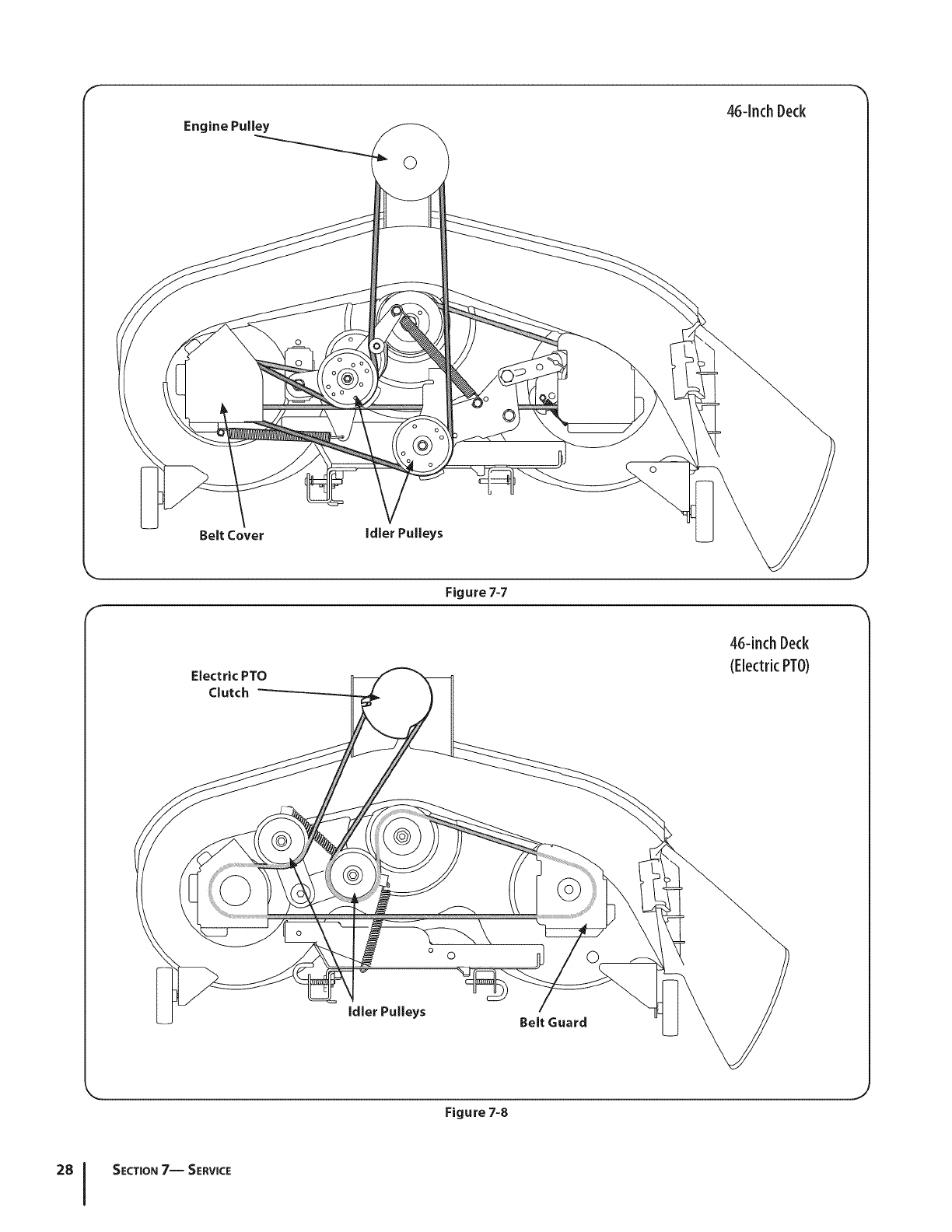
©
46qnch Deck
©
Belt Cover Idler Pulleys
Figure 7-7
Electric PTO
Clutch
46-inch Deck
(ElectricPTO)
o©
Belt Guard
Figure7-8
SECTION7-- SERVICE

Troubleshooting
Problem
Engine fails to start
Engine runs erratic
Cause
PTO/Blade engaged.
2. Spark plug wire disconnected.
3. Fuel tank empty, or stale fuel.
Remedy
1. Place knob (or lever) in disengaged (OFF)
position.
2. Connect wire to spark plug.
3. Fill tank with clean, fresh (less than 30 day-
old) gas.
4. Choke not activated.
5. Faulty spark plug.
6. Blocked fuel line.
7. Engine flooded.
& Parking brake not engaged
4. Place the throttle control in CHOKE position.
5. Clean, adjust gap or replace plug.
6. Clean fuel line and replace fuel filter.
7. Crank engine with throttle in FAST position.
8. Engage parking brake.
Engine overheats
Engine hesitates at high
RPM
Engine idles rough
Excesstve vibration
Mower will not mulch grass
Uneven cut
9. Throttle control lever not in correct starting
position.
1. Unit running with CHOKE activated.
2. Spark plug wires loose.
3. Blocked fuel line or stale fuel.
4. Ventin gas cap plugged.
5. Water or dtrt in fuel system.
6. Dirty air cleaner.
1. Engine oil level low.
2. Air flow restricted.
1. Spark plug gap too close.
1. Spark plug fouled, faulty or gap too wide.
2. Dirty air cleaner.
1. Cutting blade loose or unbalanced.
2. Damaged or bent cutting blade.
1. Engine speed too low.
2. Wet grass.
3. Excessively high grass.
4. Dull blade.
1. Deck not leveled properly.
2. Dull blade.
3. Uneven tire pressure.
9. Place throttle lever to FAST position.
1. Move the throttle contol out of the CHOKE
position.
2. Connectand tighten spark plug wire.
3. Clean fuel line; fill tank with clean, fresh
gasoline and replace fuel filter, is so equipped.
4. Clear vent or replace cap if damaged.
5. Dratn fuel tank. Refill with clean, fresh
gasoline.
6. Replace air cleaner paper element or clean
foam precleaner, is so equipped.
1. Fallcrankcase with proper amount and
weight of oil.
2. Clean grass clippings and debris from around
the engine's cooling fins and blower housing,
1. Remove spark plug and reset the gap.
1. Replace spark plug. Set plug gap.
2. Replace air cleaner element and/or clean
pre-cleaner, if so equipped.
1. Tighten blade and spindle. Balance blade.
2. Replace blade.
1. Place throttle in FAST (rabbit) position.
2. Do not mulch when grass is wet.
3. Mow once at a high cutting height, then
mow again at desired height or make a
narrower cutting swath.
4. Sharpen or replace blade.
1. Perform side-to-side deck adjustment.
2. Sharpen or replace blade.
3. Check tire pressure in all four tires.
29

ReplacementParts
DriveBelt(Transmission) 954-04165
DriveBelt(MowingDeck)42" Deck 954-04045
UpperDriveBelt(MowingDeck)46" Deck 954-04142
LowerDriveBelt (MowingDeck)46" Deck 954-0349
DriveBelt(MowingDeck)46" Deck- ElectricPTO 754-04153
DeckBlade(42"Deck) 942-0616A
DeckBlade(46"Deck)CenterBlade 942-0612A
DeckBlade(46"Deck)OuterBlade 942-0611A
DeckSpindle(42"Deck) 918-04456
DeckSpindle(46"Deck)DoublePulley- ManualPTO 918-04134B
DeckSpindle(46"Deck)SinglePulley- ManualPTO 918-0430A
DeckSpindle(46"Deck)- ElectricPTO 918-04137
DeckSpindle(42"Deck) 918-04456
DeckWheel5.0 x 1.38(twoeach) 734-0973
Battery 925-1707D
Tire (Front)15"x 6" x 6" SquareShoulder 734-1731
Tire (Rear)20" x 8"x 8" SquareShoulder 734-1730
HubCap 931-0484A
FuelTankCap 951-3111
ThrottleControl/Cable 746-04364
DischargeChuteAssembly 931-1032B
Key 925-1745
NOTE:This Operators Manual covers a range of product specifications for various models. Characteristics and features discussed
and/or illustrated in this manual may not be applicable to all models. MTD LLC reserves the right to change product specifications,
designs and equipment without notice and without incurring obligation.
NOTE: Download a complete Parts Manual free of charge at www.mtdprod ucts.com or phone (800) 800-7310 to purchase a Parts
Manual. Be sure to have your model number and serial number ready. These can be found on the model plate located under the seat.
Refer to page 2 for more information regarding locating your model and serial numbers.

Attachments&Accessories 1
Thefollowingattachmentsandaccessoriesarecompatiblefor ModelSeries610LawnTractors.Seethe retailerfromwhichyoupur-
chasedyourtractor,an authorizedMTDServiceDealerorphone(800)800-7310for informationregardingpriceandavailability.
CAUTION: Model Series 610 Lawn Tractors are NOT designed for use with any type of ground-engaging attachments
(e.g. tiller or plow). Use of this type of equipment WILL void the tractor's warra nty.
Model Number Description
0EM-190-032 42-inchTwo-stageSnowThrower
0EM-190-116 42-inchDeckMulchKit
0EM-190-118 46-inchDeckMulchKit
0EM-190-180 TwinBaggerGrassCollector(for 42-inchDecks)
0EM-190-182 TwinBaggerGrassCollector(for 46-inchDecks)
0EM-190-183 DeckWheelKit
19A-218-000 RearWeightKitw/1 SuitcaseWeight
OEM-19A-128 SuitcaseWeight
0EM-190-607 DeluxeTractorSunshade
0EM-190-679 Bumper
0EM-190-658 Tire Chains,20x 8 Tires
0EM-190-751 SnowCab
0EM-190-833 46-inchFrontDozerBlade
490-900-0025 DeckWashKit
31

Notes

SECTION11 = NOTES 33

SECTION11-- NOTES

MTD LLC (MTD), THE UNITED STATES ENVIRONMENT PROTECTION AGENCY (U. S. EPA)
EMISSION CONTROL SYSTEM WARRANTY STATEMENT
(OWNER'S DEFECT WARRANTY RIGHTS AND OBLIGATIONS)
The U.S. EPAandMTDarepleasedto explaintheemissionscontrolsystemwarrantyonyour modelyear2005and latersmalloff-roadengine.
Newsmalloff-roadenginesmust bedesigned,built andequippedto meetthe stringentanti-smogstandards.MTDmustwarrantytheemission
controlsystemonyour enginefor the periodof timelistedbelow,providedthere hasbeennoabuse,neglector impropermaintenanceof your small
off-roadengine.
Youremissioncontrolsystemmayincludepartssuchas the carburetor,aircleaner,ignitionsystem,exhaustsystem,andotherassociatedemis-
sion-relatedcomponents.
Wherea warrantableconditionexists,MTDwill repairyour smalloff-roadengineat nocost to yourincludingdiagnosis,partsandlabor.
MANUFACTURER'S WARRANTY COVERAGE:
Thisemissionscontrolsystemis warrantedfor twoyears.If anyemission-relatedpartonyour engineis defective,the partwill be repairedor
replacedby MTD.
OWNER'S WARRANTY RESPONSIBILITIES:
As the smalloff-roadengineowner,youare responsiblefor the performanceof the requiredmaintenancelistedin yourOwner'sManual.MTD
recommendsthatyou retainall your receiptscoveringmaintenancesonyoursmalloff-roadengine,but MTDcan notdenywarrantysolelyfor the
lackof receiptsor for yourfailureto ensurethe performanceto all scheduledmaintenance.
As the smalloff-roadengineowner,youshouldhoweverbeawarethatMTDmaydenyyour warrantycoverageif yoursmalloff-roadengineor part
hasfaileddue to abuse,neglect,impropermaintenanceor unapprovedmodifications.
Youare responsiblefor presentingyoursmalloff-roadengineto an AuthorizedMTDServiceDealeras soonas a problemexists.The warranted
repairsshouldbe completedin a reasonableamountof time,notto exceed30 days.
If youhaveanyquestionsregardingyour warrantyrightsand responsibilities,you shouldcontacta MTDServiceRepresentativeat 1-800-800-7310
andaddressis MTDLLC,RO.Box361131,ClevelandOH,44136-0019.
DEFECTS WARRANTY REQUIREMENTS FOR 1995 AND LATER SMALL OFF-ROAD ENGINES:
Thissectionappliesto 1995and latersmalloff-roadengines.Thewarrantyperiodbeginson the datetheengineorequipmentisdeliveredto an
ultimatepurchaser.
(a) GeneralEmissionsWarrantyCovera_
MTDmustwarrantto the ultimatepurchaserandeachsubsequentpurchaserthatthe engineis:
(1)Designed,built,andequippedso as to conformwithallapplicableregulationsadoptedbythe Air ResourcesBoardpursuantto itsauthorityin
Chapters1and2,Part5, Division26 of the HealthandSafetyCode;and
(2) Freefromdefectsinmaterialsandworkmanshipthatcausethe failureof a warrantedpartto be identicalinall materialrespectsto the part as
describedinthe enginemanufacturer'sapplicationfor certificationfor a periodof twoyears.
.(b)The warrantyonemissions-relatedpartswill be interpretedas follows:
(1)Anywarrantedpart thatis not scheduledfor replacementas requiredmaintenanceinthe writteninstructionsrequiredby Subsection(c)
mustbewarrantedfor the warrantyperioddefinedinSubsection(a)(2). If anysuchpartfailsduringthe periodof warrantycoverage,it mustbe
repairedor replacedby MTDaccordingto Subsection(4)below.Any suchpartrepairedor replacedunderthewarrantymustbewarrantedfor
the remainingwarrantyperiod.
(2)Any warrantedpartthat is scheduledonlyfor regularinspectionin the writteninstructionsrequiredby Subsection(c) mustbewarrantedfor
thewarrantyperioddefinedin Subsection(a)(2).A statementinsuchwritteninstructionsto the effectof "repairor replaceas necessary"will
not reducethe periodof warrantycoverage.Anysuchpart repairedor replacedunderwarrantymustbe warrantedforthe remainingwarranty
period.
(3) Anywarrantedpartthat whichis scheduledfor replacementas requiredmaintenancein the writteninstructionsrequiredby Subsection(c)
mustbewarrantedfor the periodof timepriorto the first scheduledreplacementpointfor thatpart.Ifthe partfailspriorto the first scheduled
replacement,the part mustbe repairedor replacedby MTDaccordingto Subsection(4) below.Any suchpart repairedor replacedunder
warrantymustbewarrantedfor the remainderof the periodpriorto thefirst scheduledreplacementpointfor the part.
(4) Repairor replacementof any warrantedpart underthe warrantyprovisionsof thisarticlemustbe performedat nochargeto the ownerat a
warrantystation.
(5) Notwithstandingthe provisionsof Subsection(4)above,warrantyservicesor repairsmustbeprovidedat all MTDdistributioncentersthat
arefranchisedto servicethe subjectengines.
(6) Theownermustnot bechargedfordiagnosticlaborthatleadsto the determinationthata warrantedpart is infact defective,providedthat
suchdiagnosticworkis performedat a warrantystation.

(7)Theenginemanufacturerisliablefordamagestootherenginecomponentsproximatelycausedbyafailureunderwarrantyofanywarranted
part.
(8)Throughouttheengine'swarrantyperioddefinedinSubsection(a)(2),MTDwillmaintainasupplyofwarrantedpartssufficienttomeetthe
expecteddemandforsuchparts.
(9)Anyreplacementpartmaybeusedintheperformanceofanywarrantymaintenanceorrepairsandmustbeprovidedwithoutchargetothe
owner.SuchusewillnotreducethewarrantyobligationsofMTD.
(10)Add-onormodifiedpartsthatarenotexemptedbytheAirResourcesBoardmaynotbeused.Theuseofanynon-exemptedadd-onor
modifiedpartsshallbegroundsfordisallowingawarrantyclaimmadeinaccordancewiththisarticle.Theenginemanufacturershallnotbe
liableunderthisarticletowarrantfailuresofwarrantedpartscausedbytheuseofnon-exemptedadd-onormodifiedpart.
(c) MTDwill includea copyof the followingemissionwarrantypartslistwitheach newengine,usingthoseportionsof the listapplicableto the
e__&gine.
(1)FuelMeteringSystem
• Coldstart enrichmentsystem(soft choke)
• Carburetorandinternalparts
• Fuel Pump
(2)Air InductionSystem
• Aircleaner
• Intakemanifold
(3) IgnitionSystem
• Sparkplug(s)
• MagnetoIgnitionSystem
(4)ExhaustSystem
(5) MiscellaneousItemsUsedinAboveSystem
• Vacuum,temperature,position,timesensitivevalvesandswitches
• Connectorsandassemblies

MANUFACTURER'S LiMiTED WARRANTY FOR
The limited warranty set forth below is given by MTD LLC with
respect to new merchandise purchased and used in the United States
and/or its territories and possessions, and by MTD Products Limited
with respect to new merchandise purchased and used in Canadaand/
or its territories and possessions (either entity respectively, "MTD").
"MTD" warrants this product (excluding its Normal WearParts and
Attachments as described below) against defects in material and
workmanship for a period of two (2) years commencing on the date
of original purchase and will, at its option, repair or replace, free of
charge, any part found to be defective in materials or workmanship.
This limited warranty shall only apply if this product has been
operated and maintained in accordance with the Operator's Manual
furnished with the product, and has not been subject to misuse,
abuse, commercial use, neglect, accident, improper maintenance,
alteration, vandalism, theft, fire, water, or damage because of other
peril or natural disaster. Damage resulting from the installation or use
of any part, accessory or attachment not approved by MTD for use
with the product(s) covered by this manual will void your warranty as
to any resulting damage.
Normal Wear Parts are warranted to befree from defects in material
and workmanship for a period of thirty (30) days from the date of
purchase. Normal wear parts include, but are not limited to items
such as: batteries, belts, blades, blade adapters, tines, grass bags,
wheels, rider deck wheels, seats, snow thrower skid shoes, friction
wheels, shave plates, auger spiral rubber and tires.
Attachments-- MTD warrants attachments for this product against
defects in material and workmanship for a period of one (1) year,
commencing on the date of the attachment's original purchase or
lease. Attachments include, but are not limited to items such as:
grass collectors and mulch kits.
HOWTO OBTAINSERVICE:Warranty service is available, WITH
PROOFOFPURCHASE,through your local authorized service dealer.
To locate the dealer in your area:
In the U.S.A.
Check your Yellow Pages, or contact MTD LLC at RO. Box 361131,
Cleveland, Ohio 44136-0019, or call 1-800-800-7310, 1-330-220-
4683 or log on to our Web site at www.mtdproducts.com.
In Canada
Contact MTD Products Limited, Kitchener, ON N2G4J1, or call 1-800-
668-1238 or log onto our Web site at www.mtdcanada.com.
This limited warranty does not provide coverage in the following
cases:
a. The engine or component parts thereof. These items may carry a
separate manufacturer's warranty. Refer to applicable manufactur-
er's warranty for terms and conditions.
b. Log splitter pumps, valves, and cylinders havea separate one-
year warranty.
c. Routine maintenance items such as lubricants, filters, blade
sharpening, tune-ups, brake adjustments, clutch adjustments,
deck adjustments, and normal deterioration of the exterior finish
due to use or exposure.
d. Service completed by someone other than an authorized service
dealer.
e. MTD does not extend any warranty for products sold or exported
outside of the United States and/or Canada,and their respective
possessions and territories, except those sold through MTD's
authorized channels of export distribution.
f. Replacement parts that are not genuine MTD parts.
g. Transportation charges and service calls.
h. MTD does not warrant this product for commercial use.
No implied warranty, including any implied warranty of
merchantability of fitness for a particular purpose, applies after
the applicable period of express written warranty above as to the
parts as identified. No other express warranty, whether written or
oral, except as mentioned above, given by any person or entity,
including a dealer or retailer, with respect to any product, shall
bind MTD. Duringthe period of the warranty, the exclusiveremedy
is repair or replacement of the product as set forth above.
The provisions as set forth in this warranty providethe sole and
exclusive remedy arising from the sale. MTD shall not be liable
for incidental orconsequential loss or damage including, without
limitation, expenses incurred for substitute or replacement lawn
care services or for rental expenses to temporarily replace a
warranted product.
Some states do not allow the exclusion or limitation of incidental
or consequential damages, or limitations on how long an implied
warranty lasts, so the above exclusions or limitations may not apply
to you.
In no event shaft recovery of any kind be greater than the amount of
the purchase price of the product sold. Alteration of safetyfeatures of
the product shall void this warranty. You assume the risk and liability
for loss, damage, or injuryto you and your property and/or to others
and their property arising out of the misuse or inability to use the
product.
This limited warranty shall not extend to anyone other than the
original purchaser or to the person for whom it was purchased as a
gift.
HOWSTATELAW RELATESTOTHIS WARRANTY: This limited
warranty gives you specific legal rights, and you may also have other
rights which vary from state to state.
IMPORTANT: Owner must present Original Proof of Purchase to
obtain warranty coverage.
MTD LLC, P.O. BOX 361131 CLEVELAND, OHiO 44136=0019; Phone: 1=800=800=7310, 1=330=220=4683
MTD Canada Limited = KITCHENER, ON N2G 4J1; Phone 1=800=668=1238
GDOC-lO0015 REV.B
