MTD 17AK9TKR099 User Manual TRACTOR Manuals And Guides 1009619L
User Manual: MTD 17AK9TKR099 17AK9TKR099 MTD TRACTOR - Manuals and Guides View the owners manual for your MTD TRACTOR #17AK9TKR099. Home:Lawn & Garden Parts:MTD Parts:MTD TRACTOR Manual
Open the PDF directly: View PDF ![]() .
.
Page Count: 96
Operator's Manual
CRRFr MRN
REVOLUTION
ZERO TURN RiDiNG MOWER
Model No. 247.28933
For answers to your questions about this product,
call 1-800-659-5917.
CAUTION: Before using
this product, read this
manual and follow all
safety rules and operating
instructions.
o SAFETY
ASSEMBLY
OPERATION
MAINTENANCE
PARTS LIST
ESPANOL, p. 58
Sears, Roebuck and Co., Hoffman Estates, IL 60179, U.S.A.
Visit our website: www.craftsman.com FORMNO.769-04608A
4/21/2009
WarrantyStatement.................... Page2
SafeOperationPractices.............. Pages3-8
SafetyLabels......................... Page9
Assembly........................... Page10
StandardReplacementParts&AttachmentsPage10
Operation........................ Pages11-17
Service&Maintenance.............. Pages18-29
Off-SeasonStorage................... Page30
Troubleshooting...................... Page31
PartsList......................... Pages32-53
RepairProtectionAgreement............ Page57
Espadol............................. Page58
ServiceNumbers................... BackPage
Craftsman Full Warranty
Whenoperatedandmaintainedaccordingtoallsuppliedinstructions,ifanynon-expendablepartofthisridingequipmentfailsduetoadefectin
materialorworkmanshipwithintwoyearsfromthedateorpurchase,call1-800-659-5917toarrangeforfreein-homerepair.
Theframeandfrontaxlewillberepairedfreeofchargeforfiveyearsfromthedateofpurchaseifdefectiveinmaterialorworkmanship.
Alloftheabovewarrantycoverageappliesforonly90daysfromthedateofpurchaseifthisridingequipmentiseverusedforcommercialor
rentalpurposes.
Inallcases,ifrepairprovesimpossible,theridingequipmentwillbereplacedfreeofchargewiththesameoranequivalentmodel.
Thebatterywillbereplacedfreeofchargefor90daysfromthedateofpurchaseifdefectiveinmaterialorworkmanship(ourtestingprovesthatit
willnotholdacharge).
ThiswarrantycoversONLYdefectsinmaterialandworkmanship.SearswillNOTpayfor:
• Expendableitemsthatbecomewornduringnormaluse,includingbutnotlimitedtoblades,sparkplugs,aircleaners,belts,andoilfilters.
• Standardmaintenanceservicing,oilchanges,ortune-ups.
• Tirereplacementorrepaircausedbypuncturesfromoutsideobjects,suchasnails,thorns,stumps,orglass.
• Tireorwheelreplacementorrepairresultingfromnormalwear,accident,orimproperoperationormaintenance.
• Repairsnecessarybecauseofoperatorabuse,includingbutnotlimitedtodamagecausedbytowingobjectsbeyondthecapabilityofthe
ridingequipment,impactingobjectsthatbendtheframeorcrankshaft,orover-speedingtheengine.
• Repairsnecessarybecauseofoperatornegligence,includingbutnotlimitedto,electricalandmechanicaldamagecausedbyimproper
storage,failuretousethepropergradeandamountofengineoil,failuretokeepthedeckclearofflammabledebris,orfailuretomaintainthe
ridingequipmentaccordingtotheinstructionscontainedintheoperator'smanual.
• Engine(fuelsystem)cleaningorrepairscausedbyfueldeterminedtobecontaminatedoroxidized(stale).Ingeneral,fuelshouldbeused
within30daysofitspurchasedate.
• Normaldeteriorationandwearoftheexteriorfinishes,orproductlabelreplacement.
ThiswarrantyappliesonlywhilethisproductiswithintheUnitedStates.
Thiswarrantygivesyouspecificlegalrights,andyoumayalsohaveotherrightswhichvaryfromstatetostate.
Sears,RoebuckandCo.,HoffmanEstates,IL60179
EngineOil: SAE30
Fuel: UnleadedGasoline
SparkPlug: Champion®RC12YC
Engine: Briggs&StrattonPlatinumV-Twin
ModelNumber.................................................................
SerialNumber.................................................................
Dateof Purchase.............................................................
Recordthe modelnumber,serialnumber
anddateof purchaseabove
©SearsBrands,LLC
2
Thissymbolpointsout importantsafetyinstructionswhich,if not
followed,couldendangerthepersonalsafetyand/orpropertyof
yourselfandothers. Readandfollowall instructionsin thismanual
beforeattemptingto operatethismachine.Failureto complywith
theseinstructionsmayresultin personalinjury.Whenyou seethis
symbol,HEEDITSWARNING!
CALIFORNIA PROPOSITION 65
EngineExhaust,someof itsconstituents,andcertainvehicle
componentscontainoremitchemicalsknownto Stateof California
to causecancerandbirthdefectsorother reproductiveharm.
Batteryposts,terminals,and relatedaccessoriescontainleadand
leadcompounds,chemicalsknownto the Stateof Californiato
causecancerandreproductiveharm.Washhandsafterhandling.
Thismachinewasbuiltto beoperatedaccordingto the safeopera-
tion practicesinthis manual.As withanytypeof powerequipment,
carelessnessorerroron the partof the operatorcan resultin serious
injury.Thismachineis capableof amputatingfingers,hands,toes
andfeetandthrowingdebris.Failureto observethe followingsafety
instructionscouldresultin seriousinjuryor death.
Your Responsibility--Restrict the useof this powermachineto
personswho read,understandandfollowthewarningsand instruc-
tionsin thismanualandon the machine.
SAVE THESE INSTRUCTIONS!
GENERAL OPERATION
•Read,understand,andfollowall instructionson the machineand
in themanual(s)beforeattemptingto assembleandoperate.
Keepthis manualina safeplacefor futureand regularreference
andfor orderingreplacementparts.
• Befamiliarwithall controlsandtheir properoperation.Knowhow
to stopthe machineanddisengagethemquickly.
• Neverallowchildrenunder14yearsoldto operatethis machine.
Children14yearsoldandover shouldreadandunderstandthe
operationinstructionsandsafetyrulesinthismanualandshould
betrainedandsupervisedbya parent.
• Neverallowadultsto operatethis machinewithoutproper
instruction.
• Tohelpavoidbladecontactor a thrownobjectinjury,keep
bystanders,helpers,childrenandpetsat least75feetfromthe
machinewhile it is in operation.Stopmachineif anyoneenters
the area.
• Thoroughlyinspectthe areawherethe equipmentis to be used.
Removeallstones,sticks,wire,bones,toys,andotherforeign
objectswhichcouldbe pickedupandthrownby the blade(s).
Thrownobjectscan causeseriouspersonalinjury.
• Planyour mowingpatternto avoiddischargeof materialtoward
roads,sidewalks,bystandersandthe like.Also,avoiddischarg-
ingmaterialagainstawall orobstructionwhichmaycause
dischargedmaterialto ricochetbacktowardthe operator.
• Alwayswear safetyglassesor safetygogglesduringoperation
andwhile performingan adjustmentor repairto protectyoureyes.
Thrownobjectswhichricochetcancauseseriousinjuryto the
eyes.
• Wearsturdy,rough-soledworkshoesandclose-fittingslacksand
shirts.Loosefittingclothesandjewelrycanbe caughtin movable
parts.Neveroperatethismachineinbarefeetorsandals.
• Beawareof the mowerandattachmentdischargedirectionand
do not pointit at anyone.Donot operatethe mowerwithoutthe
dischargecoverorentiregrasscatcherin its properplace.
Donot put handsor feetnearrotatingpartsor underthe cutting
deck. Contactwiththe blade(s)can amputatehandsandfeet.
A missingor damageddischargecovercan causebladecontact
or thrownobjectinjuries.
• Stoptheblade(s)whencrossinggraveldrives,walks,or roads
andwhile notcuttinggrass.
• Watchfor trafficwhenoperatingnearorcrossingroadways.This
machineis not intendedfor useonany public roadway.
• Donot operatethe machinewhile underthe influenceof alcohol
or drugs.
• Mowonly indaylightorgoodartificiallight.
Nevercarrypassengers.
• Disengageblade(s)beforeshiftinginto reverse.Backup slowly.
Alwayslookdownandbehindbeforeandwhile backingto avoida
back-overaccident.
3
• Slowdownbeforeturning.Operatethe machinesmoothly.Avoid
erraticoperationandexcessivespeed.
Disengageblade(s),setparkingbrake,stopengineandwaituntil
the blade(s)cometo a completestopbeforeremovinggrass
catcher,emptyinggrass,uncloggingchute,removinganygrassor
debris,or makinganyadjustments.
Neverleavea runningmachineunattended.Alwaysturnoff
blade(s),setparkingbrake,stopengineandremovekeybefore
dismounting.
Useextracare whenloadingorunloadingthe machineintoa
trailerortruck.Thismachineshouldnot bedrivenupor down
ramp(s),becausethe machinecouldtip over,causingserious
personalinjury.The machinemustbe pushedmanuallyon
ramp(s)to loador unloadproperly.
Mufflerandenginebecomehotandcan causea burn.Do not
touch.
Checkoverheadclearancescarefullybeforedrivingunderlow
hangingtree branches,wires,dooropeningsetc.,wherethe
operatormaybestruckor pulledfromthe machine,whichcould
resultinseriousinjury.
Disengageallattachmentclutchesanddepressthe brakepedal
completelybeforeattemptingto start engine.
Yourmachineisdesignedto cutnormalresidentialgrassof a
heightnomorethan 10".Do not attemptto mowthroughunusually
tall,dry grass(e.g.,pasture)orpiles of dry leaves.Drygrassor
leavesmaycontactthe engineexhaustand/or builduponthe
mowerdeckpresentinga potentialfire hazard.
Useonlyaccessoriesandattachmentsapprovedfor this machine
by the machinemanufacturer.Read,understandandfollowall
instructionsprovidedwiththe approvedaccessoryor attachment.
Fora list of approvedaccessoriesandattachments,call 1-800-
659-5917.
Dataindicatesthatoperators,age60yearsandabove,are
involvedin a largepercentageof ridingmower-relatedinjuries.
Theseoperatorsshouldevaluatetheirabilityto operatethe riding
mowersafelyenoughto protectthemselvesandothersfrom
seriousinjury.
If situationsoccurwhicharenot coveredinthismanual,usecare
andgoodjudgment.Contact1-800-659-5917for informationand
assistance.
SLOPE OPERATION
Slopesarea majorfactorrelatedto lossof controlandtip-over
accidentswhichcan resultinsevereinjuryor death.Allslopesrequire
extracaution.Ifyoucannotbackupthe slopeor if youfeel uneasyon
it, do not mowit.
Foryoursafety,use the SlopeGuideincludedas partof this manual
to measureslopesbeforeoperatingthis machineona slopedor hilly
area. Ifthe slopeis greaterthan15degreesas shownonthe Slope
Guide,do notoperatethis machineonthatareaor seriousinjurycould
result.
Do:
oMowupanddown slopes,not across.Exerciseextremecaution
whenchangingdirectionon slopes.
• Watchfor holes,ruts,bumps,rocks,orother hiddenobjects.
Uneventerraincouldoverturnthe machine.Tallgrasscan hide
obstacles.
Useslowspeed.Choosea lowenoughspeedsettingso that
you will nothaveto stopor shiftwhileon the slope.Tiresmay
lose tractionon slopeseventhoughthe brakesarefunctioning
properly.Alwayskeepmachinein gearwhen goingdownslopes
to takeadvantageof enginebrakingaction.
• Followthe manufacturer'srecommendationsfor wheelweights
or counterweightsto improvestability.Forrecommendations,call
1-800-659-5917.
• Useextracarewithgrasscatchersor otherattachments.These
can changethe stabilityof the machine.
Keepallmovementonthe slopesslowandgradual.Do not make
suddenchangesinspeedor direction.Rapidengagementor
brakingcouldcausethe frontof the machineto lift andrapidlyflip
overbackwardswhichcouldcauseseriousinjury.
• Avoidstartingorstoppingona slope.Iftireslosetraction,disen-
gagethe blade(s)andproceedslowlystraightdownthe slope.
DoNot:
• Donot turnon slopesunlessnecessary;then,turnslowlyand
graduallydownhill,if possible.
• Donot mowneardrop-offs,ditchesor embankments.The mower
could suddenlyturnover if a wheelis overthe edgeof a cliff,
ditch,or if an edgecavesin.
• Donot try to stabilizethe machineby puttingyourfooton the
ground.
• Donot usea grasscatcheron steepslopes.
• Donot mowon wetgrass.Reducedtractioncouldcausesliding.
• Donot attemptto coastdownhill.Over-speedingmaycausethe
operatorto lose controlof the machineresultingin seriousinjury
or death.
• Donot towheavypull behindattachments(e.g.loadeddumpcart,
lawn roller,etc.)on slopesgreaterthan5 degrees.Whengoing
down hill,the extraweighttendsto pushthe tractorandmay
causeyou to loosecontrol.(e.g.tractormayspeedup,braking
and steeringabilityare reduced,attachmentmayjack-knifeand
causetractorto overturn).
4
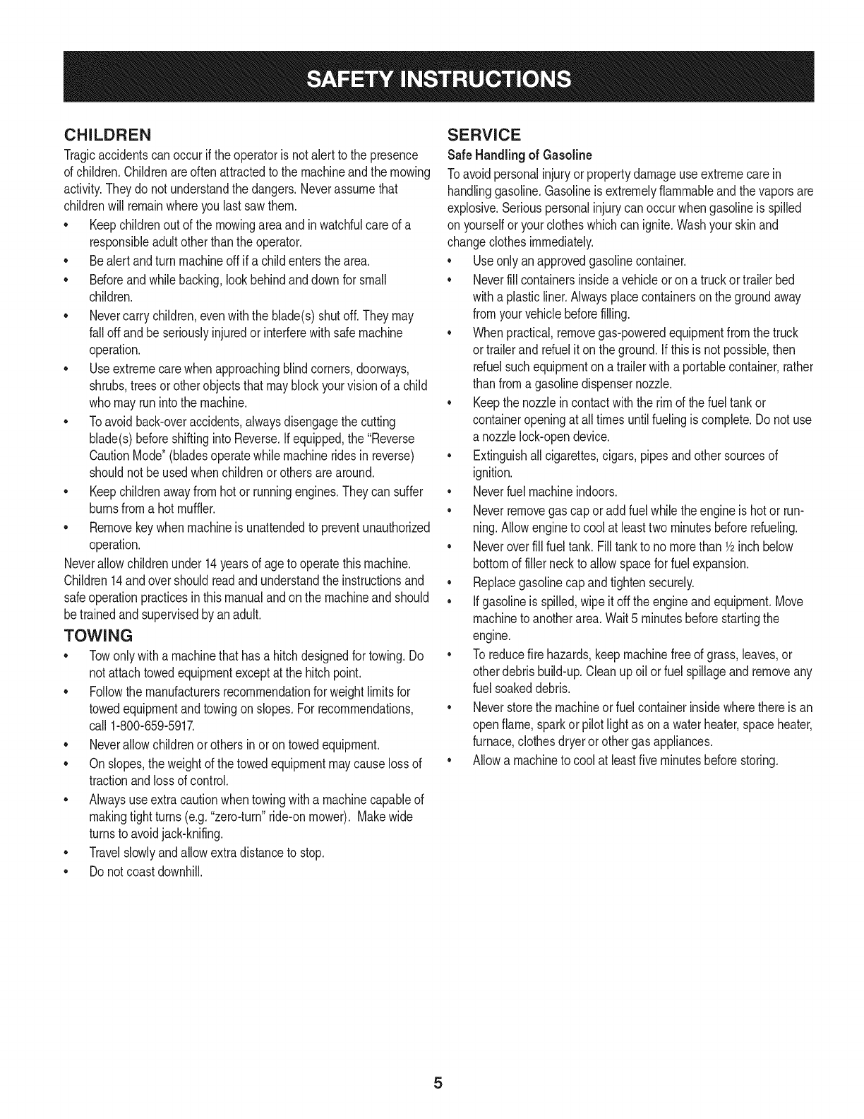
CHILDREN
Tragicaccidentscanoccurifthe operatoris notalert to the presence
of children.Childrenareoftenattractedto the machineandthe mowing
activity.Theydo notunderstandthe dangers.Neverassumethat
childrenwill remainwhereyou lastsawthem.
• Keepchildrenout of the mowingareaand inwatchfulcare of a
responsibleadultotherthanthe operator.
• Bealert andturnmachineoff ifa childentersthe area.
• Beforeandwhilebacking,lookbehindanddownfor small
children.
Nevercarrychildren,evenwiththe blade(s)shutoff.Theymay
fall offandbe seriouslyinjuredorinterferewithsafemachine
operation.
• Useextremecarewhenapproachingblindcorners,doorways,
shrubs,treesorotherobjectsthatmayblockyourvisionof a child
whomayrunintothe machine.
Toavoidback-overaccidents,alwaysdisengagethe cutting
blade(s)beforeshiftingintoReverse.Ifequipped,the "Reverse
CautionMode"(bladesoperatewhilemachineridesinreverse)
shouldnotbe usedwhenchildrenor othersarearound.
Keepchildrenawayfromhotor runningengines.Theycansuffer
burnsfroma hotmuffler.
• Removekeywhenmachineisunattendedto preventunauthorized
operation.
Neverallowchildrenunder14yearsof ageto operatethis machine.
Children14andovershouldreadandunderstandthe instructionsand
safeoperationpracticesinthismanualandon the machineandshould
betrainedandsupervisedbyan adult.
TOWING
Towonlywitha machinethathasa hitchdesignedfor towing.Do
not attachtowedequipmentexceptat the hitchpoint.
Followthe manufacturersrecommendationforweightlimitsfor
towedequipmentandtowingonslopes.For recommendations,
call 1-800-659-5917.
Neverallowchildrenor othersinoron towedequipment.
Onslopes,theweightof thetowedequipmentmaycauselossof
tractionandlossof control.
Alwaysuseextracautionwhentowingwitha machinecapableof
makingtightturns(e.g."zero-turn"ride-onmower). Makewide
turnsto avoidjack-knifing.
Travelslowlyandallowextradistanceto stop.
Do notcoastdownhill.
SERVICE
SafeHandlingof Gasoline
Toavoidpersonalinjuryorpropertydamageuse extremecarein
handlinggasoline.Gasolineisextremelyflammableandthe vaporsare
explosive.Seriouspersonalinjurycanoccurwhengasolineis spilled
on yourselforyour clotheswhichcan ignite.Washyourskinand
changeclothesimmediately.
• Useonly anapprovedgasolinecontainer.
Neverfill containersinsidea vehicleoron a truckortrailer bed
witha plasticliner.Alwaysplacecontainerson the groundaway
fromyourvehiclebeforefilling.
Whenpractical,removegas-poweredequipmentfromthe truck
or trailerandrefueliton theground.Ifthis isnot possible,then
refuelsuchequipmentona trailerwitha portablecontainer,rather
than froma gasolinedispensernozzle.
Keepthe nozzleincontactwiththe rim of the fueltankor
containeropeningat all timesuntilfuelingiscomplete.Donot use
a nozzlelock-opendevice.
Extinguishall cigarettes,cigars,pipesandothersourcesof
ignition.
• Neverfuel machineindoors.
Neverremovegascap or addfuelwhilethe engineis hotor run-
ning.Allowengineto coolat leasttwominutesbeforerefueling.
Neveroverfill fuel tank. Filltankto no morethan 1/2inchbelow
bottomof filler neckto allowspaceforfuel expansion.
• Replacegasolinecap andtightensecurely.
• Ifgasolineis spilled,wipeitoff the engineandequipment.Move
machineto anotherarea.Wait5 minutesbeforestartingthe
engine.
• To reducefire hazards,keepmachinefree of grass,leaves,or
otherdebrisbuild-up.Cleanup oilor fuel spillageandremoveany
fuel soakeddebris.
• Neverstorethe machineor fuelcontainerinsidewherethere isan
openflame,sparkor pilotlight as ona waterheater,spaceheater,
furnace,clothesdryeror othergasappliances.
Allowa machineto coolat leastfiveminutesbeforestoring.
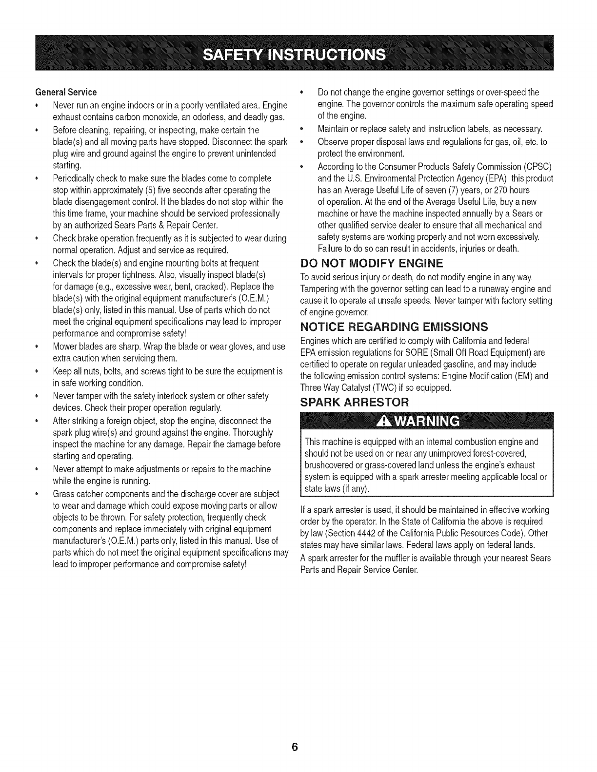
GeneralService
• Neverrunanengineindoorsorinapoorlyventilatedarea.Engine
exhaustcontainscarbonmonoxide,anodorless,anddeadlygas.
• Beforecleaning,repairing,orinspecting,makecertainthe
blade(s)andallmovingpartshavestopped.Disconnectthespark
plugwireandgroundagainsttheenginetopreventunintended
starting.
• Periodicallychecktomakesurethebladescometocomplete
stopwithinapproximately(5)fivesecondsafteroperatingthe
bladedisengagementcontrol.Ifthebladesdonotstopwithinthe
thistimeframe,yourmachineshouldbeservicedprofessionally
byanauthorizedSearsParts&RepairCenter.
• Checkbrakeoperationfrequentlyasitissubjectedtowearduring
normaloperation.Adjustandserviceasrequired.
• Checktheblade(s)andenginemountingboltsatfrequent
intervalsforpropertightness.Also,visuallyinspectblade(s)
fordamage(e.g.,excessivewear,bent,cracked).Replacethe
blade(s)withtheoriginalequipmentmanufacturer's(O.E.M.)
blade(s)only,listedinthismanual.Useofpartswhichdonot
meettheoriginalequipmentspecificationsmayleadtoimproper
performanceandcompromisesafety!
• Mowerbladesaresharp.Wrapthebladeorweargloves,anduse
extracautionwhenservicingthem.
• Keepallnuts,bolts,andscrewstighttobesuretheequipmentis
insafeworkingcondition.
• Nevertamperwiththe safetyinterlocksystemor othersafety
devices.Checktheir properoperationregularly.
• Afterstrikinga foreignobject,stopthe engine,disconnectthe
sparkplugwire(s)andgroundagainstthe engine.Thoroughly
inspectthe machinefor anydamage.Repairthe damagebefore
startingandoperating.
• Neverattemptto makeadjustmentsor repairsto the machine
whilethe engineis running.
• Grasscatchercomponentsandthe dischargecoverare subject
to wearanddamagewhichcouldexposemovingpartsor allow
objectsto bethrown.Forsafetyprotection,frequentlycheck
componentsand replaceimmediatelywithoriginalequipment
manufacturer's(O.E.M.)partsonly,listedinthis manual.Useof
partswhichdo not meetthe originalequipmentspecificationsmay
leadto improperperformanceandcompromisesafety!
• Donot changethe enginegovernorsettingsorover-speedthe
engine.The governorcontrolsthe maximumsafeoperatingspeed
of the engine.
Maintainor replacesafetyandinstructionlabels,as necessary.
• Observeproperdisposallawsandregulationsfor gas,oil, etc.to
protecttheenvironment.
• Accordingto the ConsumerProductsSafetyCommission(CPSC)
andthe U.S.EnvironmentalProtectionAgency(EPA),this product
has anAverageUsefulLifeof seven(7)years,or 270hours
of operation.At the endof the AverageUsefulLife,buy anew
machineor havethe machineinspectedannuallybya Searsor
otherqualifiedservicedealerto ensurethatall mechanicaland
safetysystemsareworkingproperlyandnot wornexcessively.
Failureto doso can resultinaccidents,injuriesor death.
DO NOT MODIFY ENGINE
Toavoid seriousinjuryor death,do notmodifyengineinanyway.
Tamperingwiththe governorsettingcanleadto a runawayengineand
causeit to operateat unsafespeeds.Nevertamperwithfactorysetting
of enginegovernor.
NOTICE REGARDING EMISSIONS
Engineswhicharecertifiedto complywithCaliforniaandfederal
EPAemissionregulationsfor SORE(SmallOffRoadEquipment)are
certifiedto operateon regularunleadedgasoline,andmayinclude
the followingemissioncontrolsystems:EngineModification(EM)and
ThreeWayCatalyst(TWO)if so equipped.
SPARK ARRESTOR
Thismachineis equippedwithan internalcombustionengineand
shouldnotbe usedonor nearanyunimprovedforest-covered,
brushcoveredorgrass-coveredlandunlessthe engine'sexhaust
systemisequippedwitha sparkarrestermeetingapplicablelocalor
statelaws(if any).
Ifa sparkarresteris used,it shouldbe maintainedin effectiveworking
orderby the operator.Inthe Stateof Californiatheaboveis required
by law (Section4442of the CaliforniaPublicResourcesCode).Other
statesmayhavesimilarlaws.Federallawsapplyonfederallands.
A sparkarresterfor the mufflerisavailablethroughyournearestSears
PartsandRepairServiceCenter.
6
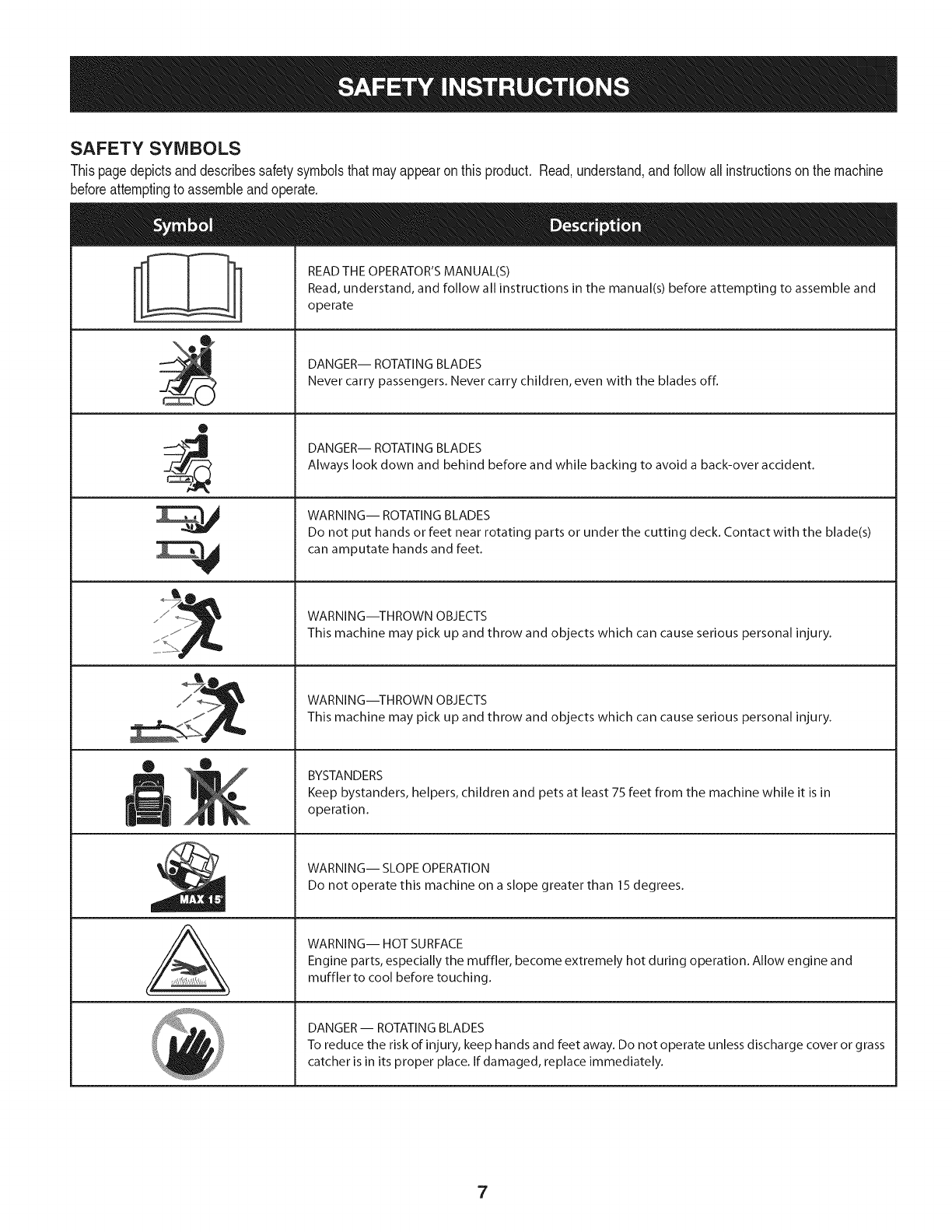
SAFETY SYMBOLS
Thispagedepictsanddescribessafetysymbolsthatmayappearonthis product. Read,understand,andfollowallinstructionson the machine
beforeattemptingto assembleandoperate.
0
A
READ THE OPERATOR'S MANUAL(S)
Read, understand, and follow all instructions in the manual(s) before attempting to assemble and
operate
DANGER-- ROTATING BLADES
Never carry passengers. Never carry children, even with the blades off.
DANGER-- ROTATING BLADES
Always look down and behind before and while backing to avoid a back-over accident.
WARNING-- ROTATING BLADES
Do not put hands or feet near rotating parts or under the cutting deck. Contact with the blade(s)
can amputate hands and feet.
WARNING--THROWN OBJECTS
This machine may pick up and throw and objects which can cause serious personal injury.
WARNING--THROWN OBJECTS
This machine may pick up and throw and objects which can cause serious personal injury.
BYSTANDERS
Keep bystanders, helpers, children and pets at least 75 feet from the machine while it is in
operation.
WARNING-- SLOPE OPERATION
Do not operate this machine on a slope greater than 15 degrees.
WARNING-- HOT SURFACE
Engine parts, especially the muffler, become extremely hot during operation. Allow engine and
muffler to cool before touching.
DANGER-- ROTATING BLADES
To reduce the risk of injury, keep hands and feet away. Do not operate unless discharge cover or grass
catcher is in its proper place. If damaged, replace immediately.
7
0o
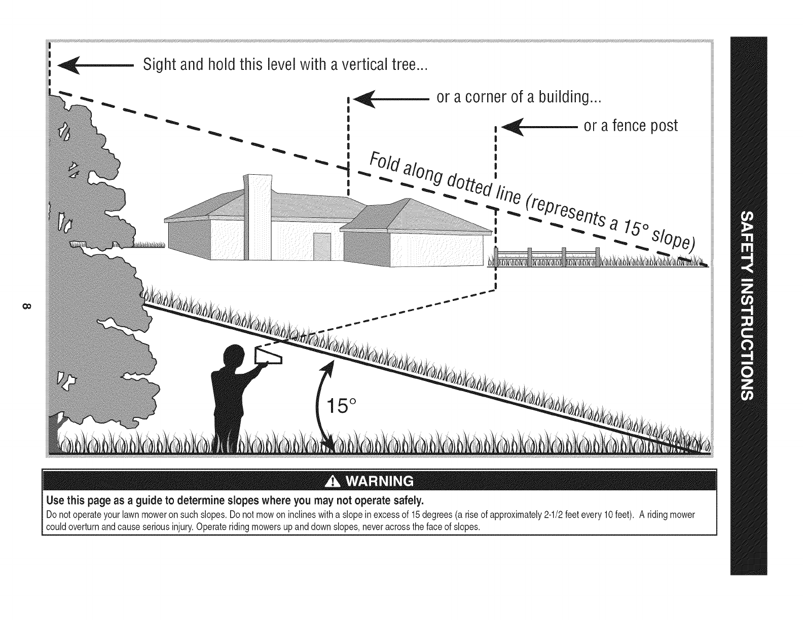
Sight andhold this levelwith a verticaltree...
|
|
|
!
!
|
|
!
|
or a corner of a building...
,_ or afence post
|
|
#Old ',
_. :,uog dotto,_'.
"T,"_ _Presen_ts alo
, ._ _lOpe_
|
I
15 °
Use this page as a guideto determine slopes where you may not operate safely.
Donot operateyourlawnmoweron suchslopes.Do notmowon inclineswitha slope inexcessof 15degrees(a rise of approximately2-1/2feetevery10feet). A ridingmower
couldoverturnandcauseseriousinjury.Operateridingmowersupanddown slopes,neveracrossthe faceof slopes.
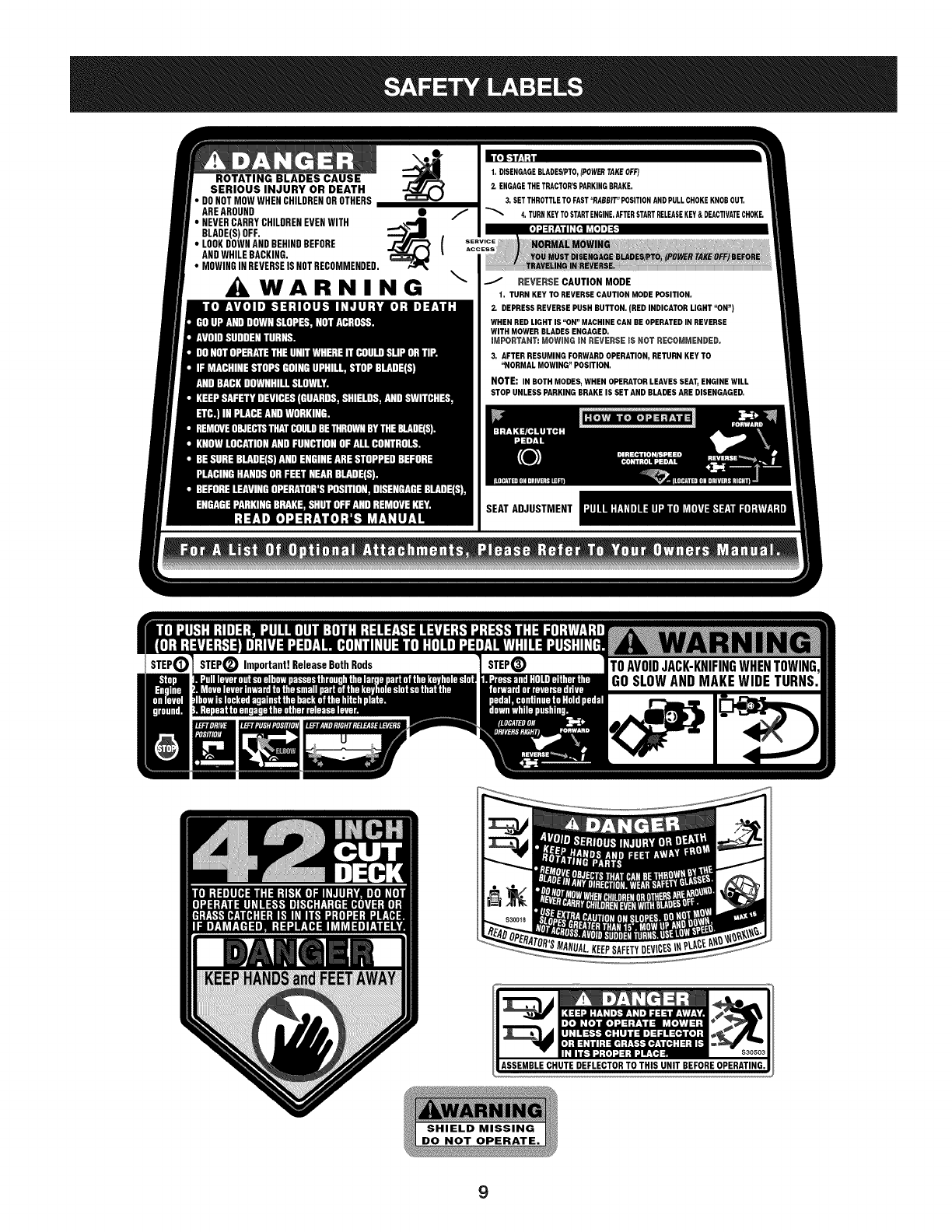
ROTATING BLADES CAUSE
SERIOUS INJURY OR DEATH
• DONOTMOWWHENCHILDRENOROTHERS
AREAROUND •
•BLADE(s)NEVERCARRYoFF.CHILDRENEVENWITH _'_"4m (
•LOOKDOWNANDBEHINDBEFORE
ANDWHILEBACKING.
• MOWINGINREVERSEISNOTRECOMMENDED.
WARNING \
t. DISENGAGEBLADES/PTO,(POWERTAKEOFF)
2. ENGAGETHETRACTOR'SPARKINGBRAKE.
3. SETTHROTTLETOFAST"RABBIT"POSITIONANDPULLCHOKEKNOBOUT.
4. TURNKEYTOSTARTENGINE.AFTERSTARTRELEASEKEY&DEACTIVATECHOKE.
REVERSE CAUTION MODE
t. TURN KEY TO REVERSE CAUTION MODE POSITION.
2, DEPRESS REVERSE PUSH BUTTON. (BED INDICATOR LIGHT "ON")
WHEN RED LIGHT IS "ON" MACHINE CAN BE OPERATED IN REVERSE
WITH MOWER BLADES ENGAGED.
mMPORTANT: MOWING mN REVERSE iS NGT RECGMMENDED.
3, AFTER RESUMING FORWARD OPERATION, RETURN KEY TO
"NORMAL MOWING" POSITION.
NOTE: IN BOTH MODES, WHEN OPERATOR LEAVES SEAT, ENGINE WILL
STOP UNLESS PARKING BRAKE IS SET AND BLADES ARE DISENGAGED,
SEATADJUSTMENT
9
IMPORTANT:Yourtractoris shippedwithmotoroil in theengine.
However,you MUSTcheckthe oil levelbeforeoperating.Referto the
Service& Maintenancesectionfor instructionson checkingtheoil
level.
NOTE: Ifthe batteryis put intoserviceafterthedate shownontop of
battery,chargethebatteryas instructedinthe Service& Maintenance
sectionof thismanual_the tractor.
OPENING THE TRACTOR HOOD
Toattachthe batterycablesandcheckthe engineoil levelthe hood
mustbeopen. Locatethe hoodlift notch(Referto Figure2 on page11)
at the front/centerof the dash panel.Graspingthe hoodat thenotch,
lift andpivotthe hoodforwardto open.
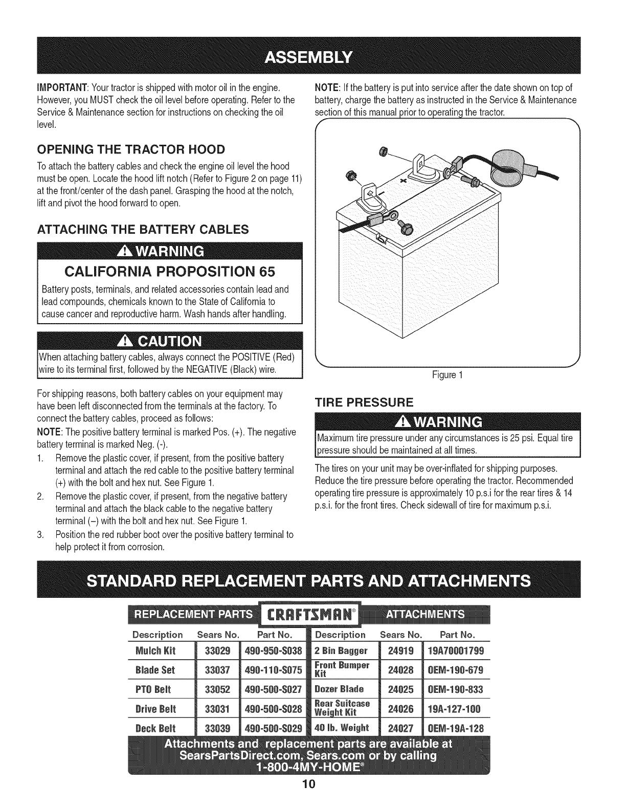
ATTACHING THE BATTERY CABLES
CALIFORNIA PROPOSITION 65
Batteryposts,terminals,andrelatedaccessoriescontainleadand
leadcompounds,chemicalsknownto the Stateof Californiato
causecancerandreproductiveharm.Washhandsafterhandling.
Whenattachingbatterycables,alwaysconnectthe POSITIVE(Red)
wireto its terminalfirst,followedby the NEGATIVE(Black)wire. Figure1
Forshippingreasons,bothbatterycablesonyourequipmentmay
havebeenleftdisconnectedfrom the terminalsat the factory.To
connectthe batterycables,proceedasfollows:
NOTE:Thepositivebatteryterminalis markedPos.(+).The negative
batteryterminalis markedNeg.(-).
1. Removethe plasticcover,if present,fromthe positivebattery
terminaland attachthe redcableto the positivebatteryterminal
(+)with the bolt andhexnut.See Figure1.
2. Removethe plasticcover,if present,fromthe negativebattery
terminaland attachthe blackcableto the negativebattery
terminal(-) withthe bolt andhex nut.SeeFigure1.
3. Positionthe redrubberbootoverthe positivebatteryterminalto
helpprotectit fromcorrosion.
TIRE PRESSURE
3ressureshouldbemaintainedatall times.
The tiresonyour unitmaybeover-inflatedfor shippingpurposes.
Reducethe tire pressurebeforeoperatingthe tractor.Recommended
operatingtire pressureis approximately10p.s.ifor the reartires & 14
p.s.i,forthe fronttires.Checksidewallof tire for maximump.s.i.
10
f
K
A\
P
Q
F
CE
J
L--
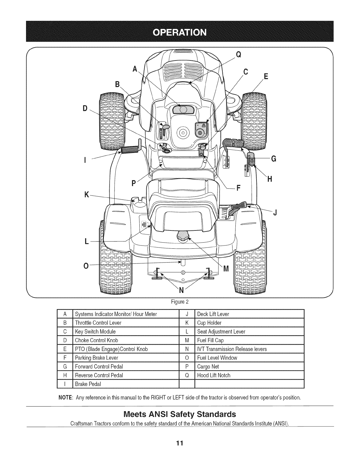
Figure2
A SystemsIndicatorMonitor/HourMeter
B ThrottleControlLever
C KeySwitchModule
D ChokeControlKnob
E PTO(BladeEngage)ControlKnob
F ParkingBrakeLever
G ForwardControlPedal
H ReverseControlPedal
J DeckLiftLever
K CupHolder
L SeatAdjustmentLever
M FuelFillCap
N IVTTransmissionReleaselevers
0 FuelLevelWindow
P CargoNet
Q HoodLiftNotch
I BrakePedal
NOTE: Any referenceinthismanualto the RIGHTor LEFTside of the tractoris observedfromoperator'sposition.
Meets ANSI Safety Standards
CraftsmanTractorsconformto the safetystandardof theAmericanNationalStandardsInstitute(ANSI).
11
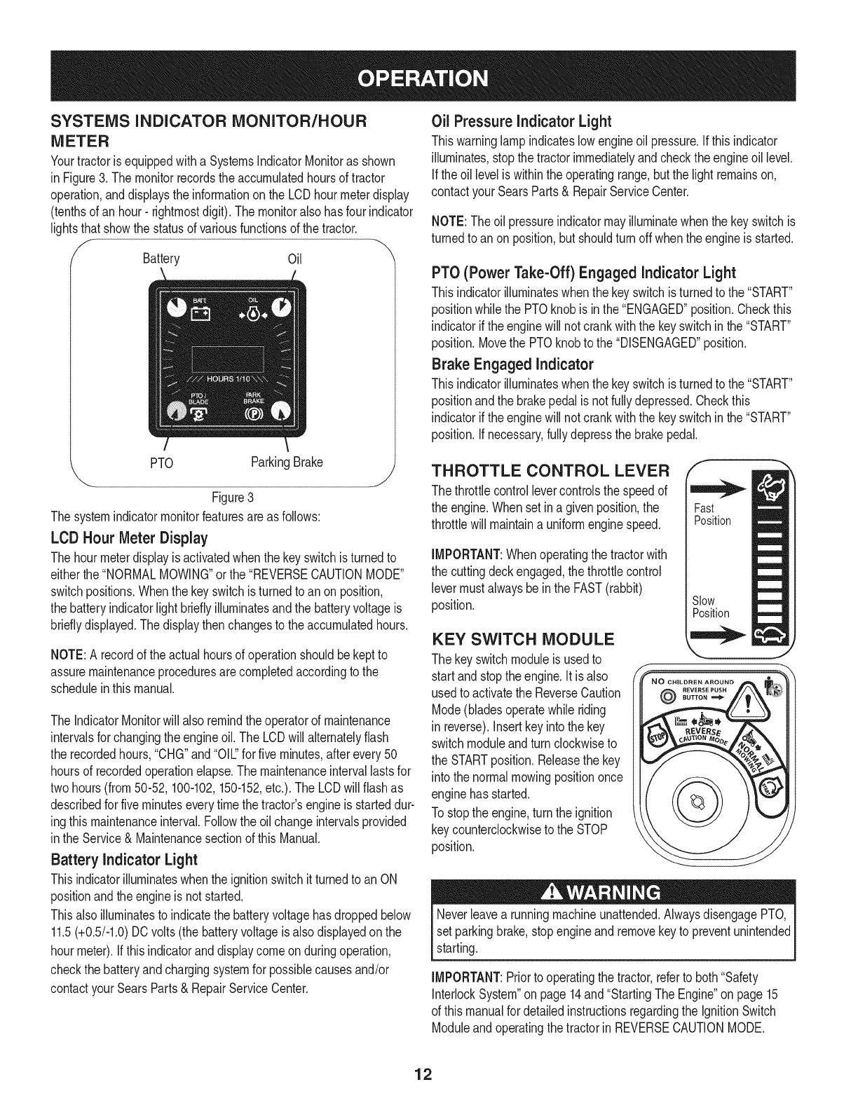
SYSTEMS iNDiCATOR MONITOR/HOUR
METER
Yourtractorisequippedwitha SystemsIndicatorMonitoras shown
in Figure3. The monitorrecordstheaccumulatedhoursof tractor
operation,anddisplaysthe informationonthe LCDhourmeterdisplay
(tenthsof an hour- rightmostdigit).The monitoralso hasfour indicator
lightsthat showthe statusof variousfunctionsof thetractor.
Battery Oil
PTO ParkingBrake
"-.. j
Figure3
The systemindicatormonitorfeaturesareas follows:
LCD Hour Meter Display
The hourmeterdisplayis activatedwhenthe keyswitchis turnedto
eitherthe"NORMALMOWING"orthe "REVERSECAUTIONMODE"
switchpositions.Whenthe keyswitchis turnedto anon position,
the batteryindicatorlight brieflyilluminatesandthe batteryvoltageis
bridly displayed.The displaythenchangesto the accumulatedhours.
NOTE:A recordof the actualhoursof operationshouldbe keptto
assuremaintenanceproceduresarecompletedaccordingto the
scheduleinthismanual.
The IndicatorMonitorwill also remindtheoperatorof maintenance
intervalsfor changingtheengineoil. The LCDwill alternatelyflash
the recordedhours,"CHG"and"Oil" for fiveminutes,afterevery50
hoursof recordedoperationelapse.The maintenanceintervallastsfor
twohours(from50-52,100-102,150-152,etc.).The LCDwillflashas
describedfor fiveminuteseverytimethe tractor'sengineis starteddur-
ingthis maintenanceinterval.Followthe oilchangeintervalsprovided
inthe Service& Maintenancesectionof thisManual.
Battery indicator Light
Thisindicatorilluminateswhenthe ignitionswitchitturnedto an ON
positionandtheengineis not started.
Thisalsoilluminatesto indicatethe batteryvoltagehasdroppedbelow
11.5(+0.5/-1.0)DCvolts(the batteryvoltageisalso displayedonthe
hourmeter).If thisindicatorand displaycomeonduringoperation,
checkthe batteryandchargingsystemfor possiblecausesand/or
contactyourSearsParts& RepairServiceCenter.
Oil Pressureindicator Light
Thiswarninglamp indicateslowengineoil pressure.Ifthisindicator
illuminates,stopthetractorimmediatelyandcheckthe engineoil level.
Ifthe oil leveliswithinthe operatingrange,butthe light remainson,
contactyour SearsParts& RepairServiceCenter.
NOTE:The oilpressureindicatormayilluminatewhenthe keyswitchis
turnedto an onposition,but shouldturn off whentheengineisstarted.
PTO(Power Take-Off) Engaged indicator Light
Thisindicatorilluminateswhenthe keyswitchis turnedto the "START"
positionwhilethe PTOknob is inthe "ENGAGED"position.Checkthis
indicatorif the enginewill not crankwiththe keyswitchin the"START"
position.Movethe PTOknobto the "DISENGAGED"position.
Brake Engaged indicator
Thisindicatorilluminateswhenthe keyswitchis turnedto the "START"
positionandthe brakepedalis notfullydepressed.Checkthis
indicatorifthe enginewill not crankwiththe keyswitchinthe"START"
position.If necessary,fullydepressthe brakepedal.
THROTTLE CONTROL LEVER
The throttlecontrollevercontrolsthe speedof
the engine.Whenset ina givenposition,the
throttlewill maintaina uniformenginespeed.
IMPORTANT:Whenoperatingthe tractorwith
the cuttingdeckengaged,thethrottlecontrol
levermustalwaysbein the FAST(rabbit)
position.
KEY SWITCH MODULE
The keyswitchmoduleis usedto
start andstoptheengine.It is also
usedto activatethe ReverseCaution
Mode(bladesoperatewhile riding
in reverse).Insertkeyintothe key
switchmoduleandturn clockwiseto
the STARTposition.Releasethe key
intothe normalmowingpositiononce
enginehasstarted.
To stopthe engine,turn the ignition
keycounterclockwiseto the STOP
position.
@
Fast
Position
Slow
Position
Neverleavea runningmachineunattended.AlwaysdisengagePTO,
setparkingbrake,stopengineand removekeyto preventunintended
starting.
IMPORTANT:Priorto operatingthe tractor,referto both"Safety
InterlockSystem"on page14and"StartingTheEngine"on page15
of this manualfor detailedinstructionsregardingthe IgnitionSwitch
ModuleandoperatingthetractorinREVERSECAUTIONMODE.
12
Nevermovethe keyintothe Startpositionwhiletheengineis
running.Doingso maycausedamageto yourengine'sstarter.
CHOKECONTROL
Thechokecontrolknobis locatedonthe lowerIdt sideof the dash
paneland isactivatedby pullingoutward.Activatingthe chokecontrol
closesthechokeplateonthe carburetorandaids instartingthe
engine.
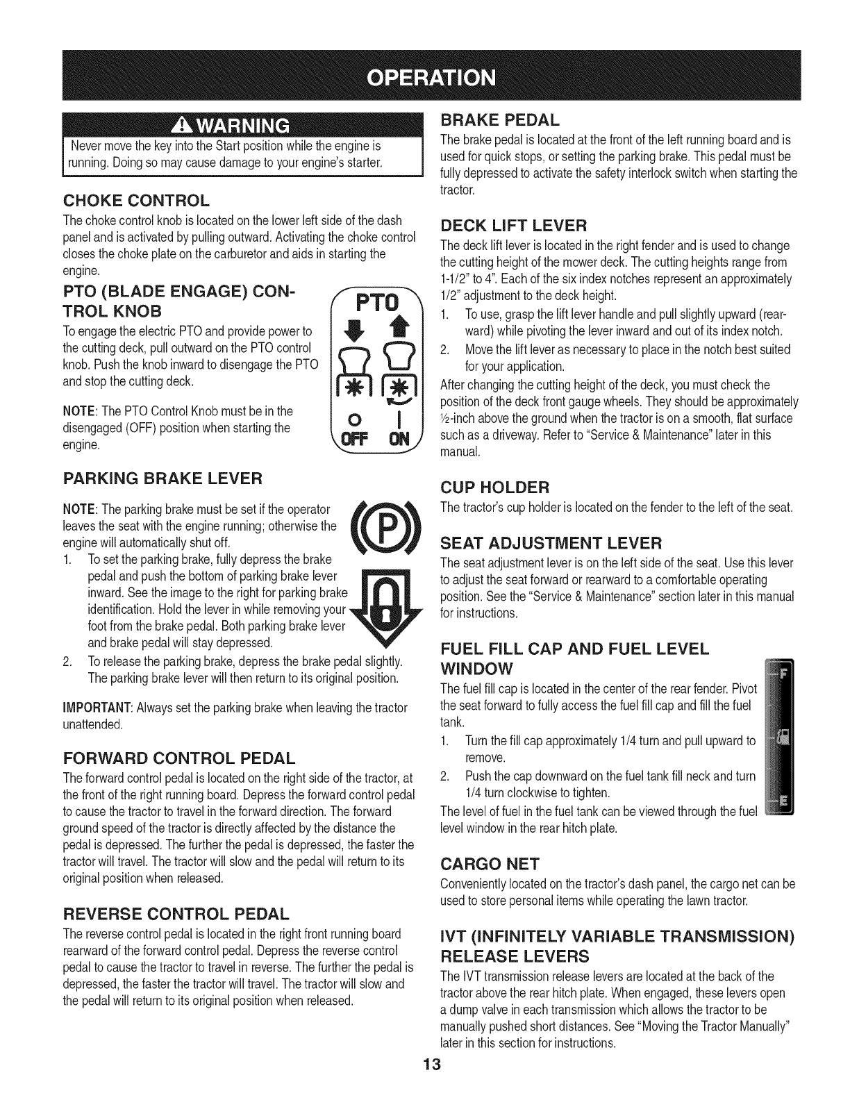
PTO (BLADE ENGAGE) CON-
TROL KNOB
Toengagethe electricPTOand providepowerto
the cuttingdeck, pulloutwardonthe PTOcontrol
knob.Pushthe knobinwardto disengagethe PTO
andstopthecuttingdeck.
NOTE:The PTOControlKnobmustbe inthe
disengaged(OFF)positionwhen startingthe
engine.
FPTO
oI
BRAKE PEDAL
The brakepedalis locatedat the frontof the left runningboardand is
usedfor quickstops,or settingtheparkingbrake.Thispedalmustbe
fullydepressedto activatethe safetyinterlockswitchwhen startingthe
tractor.
DECK LIFT LEVER
The decklift leveris locatedinthe rightfenderandis usedto change
the cuttingheightof the mowerdeck.Thecuttingheightsrangefrom
1-1/2"to 4".Eachof the six indexnotchesrepresentanapproximately
1/2"adjustmentto the deckheight.
1. To use,graspthe lift leverhandleandpullslightlyupward(rear-
ward)while pivotingthe leverinwardandout of its indexnotch.
2. Movethe liftleveras necessaryto placeinthe notchbestsuited
for yourapplication.
Afterchangingthe cuttingheightof thedeck, youmustcheckthe
positionof the deckfrontgaugewheels.Theyshouldbeapproximately
lbinch abovethe groundwhenthe tractoris ona smooth,flatsurface
suchas a driveway.Referto "Service& Maintenance"laterinthis
manual.
PARKING BRAKE LEVER
NOTE:Theparkingbrakemustbesetif the operator ,_,_%,
leavesthe seatwiththe enginerunning;otherwisethe tL )
enginewill automaticallyshutoff.
1. Tosetthe parkingbrake,fullydepressthe brake
pedaland pushthe bottomof parkingbrakelever
inward.Seethe imageto the rightfor parkingbrake
identification.Holdthe leverinwhile removingyour
footfromthe brakepedal.Bothparkingbrakelever
andbrakepedalwill staydepressed.
2. Toreleasethe parkingbrake,depressthe brakepedalslightly.
Theparkingbrakeleverwill then returnto its originalposition.
IMPORTANT:Alwayssetthe parkingbrakewhen leavingthetractor
unattended.
FORWARD CONTROL PEDAL
Theforwardcontrolpedalis locatedonthe rightsideof the tractor,at
the frontof the rightrunningboard.Depressthe forwardcontrolpedal
to causethe tractorto travelinthe forwarddirection.The forward
groundspeedof thetractorisdirectlyaffectedby the distancethe
pedalisdepressed.Thefurtherthe pedalisdepressed,thefasterthe
tractorwill travel.Thetractorwill slowandthe pedalwill returnto its
originalpositionwhenreleased.
REVERSE CONTROL PEDAL
The reversecontrolpedalis locatedinthe rightfrontrunningboard
rearwardof theforwardcontrolpedal.Depressthe reversecontrol
pedalto causethetractorto travelin reverse.Thefurtherthe pedalis
depressed,the fasterthetractorwill travel.The tractorwill slowand
the pedalwill returnto itsoriginalpositionwhen released.
CUP HOLDER
The tractor'scup holderis locatedon the fenderto the left of the seat.
SEAT ADJUSTMENT LEVER
The seatadjustmentleveris on the leftside of the seat.Usethis lever
to adjustthe seatforwardor rearwardto acomfortableoperating
position.Seethe "Service&Maintenance"sectionlaterin thismanual
for instructions.
FUEL FILL CAP AND FUEL LEVEL
WINDOW
The fuelfill cap is locatedinthe centerof the rearfender.Pivot
the seatforwardto fullyaccessthe fuelfill cap andfill the fuel
tank.
1. Turnthefill capapproximately1/4 turnandpull upwardto
remove.
2. Pushthe cap downwardon the fueltankfill neckandturn
1/4turn clockwiseto tighten.
The levelof fuel inthe fueltankcan beviewedthroughthefuel
levelwindowin the rearhitchplate.
CARGO NET
Convenientlylocatedon thetractor'sdashpanel,thecargo netcan be
usedto storepersonalitemswhileoperatingthe lawntractor.
IVT (INFINITELY VARIABLE TRANSMISSION)
RELEASE LEVERS
The IVTtransmissionreleaseleversare locatedat the backof the
tractorabovethe rearhitchplate.Whenengaged,theseleversopen
a dumpvalveineachtransmissionwhichallowsthetractorto be
manuallypushedshortdistances.See"Movingthe TractorManually"
laterinthis sectionfor instructions.
13
Avoid Serious injury or Death
• Goupanddown slopes,not across.
Avoidsuddenturns.
Do notoperatethe unit whereitcouldslip ortip.
If machinestopsgoinguphill,stopbladesandbackdownhill
slowly.
• Do notmowwhenchildrenor othersarearound.
• Nevercarrychildren,evenwithbladesoff.
• Lookdownandbehindbeforeand whilebacking.
• Keepsafetydevices(guards,shields,andswitches)in place
andworking.
• Removeobjectsthatcouldbethrownbythe blades.
• Knowlocationandfunctionof all controls.
• Besure bladesandengineare stoppedbeforeplacinghandsor
feetnearblades.
• Beforeleavingoperator'sposition,stoptractor,disengage
blades,engageparkingbrake,shutengineoff,and removekey.
Read Operator's Manual
OIL AND GAS FILL-UP
0il
IMPORTANT:Yourtractoris shippedwithmotoroil in theengine.
However,you MUSTcheckthe oil levelbeforeoperating.Seethe
"ServiceandMaintenance"section.
Gasoline
Useextremecarewhenhandlinggasoline.Gasolineis extremely
flammableandthe vaporsareexplosive.Neverfuel machine
indoorsor whilethe engineis hot or running.Extinguishcigarettes,
cigars,pipes,andothersourcesof ignition.
NOTE: Purchasegasolinein smallquantities.Donot usegasolineleft
overfromthe previousseason,to minimizegumdepositsin the fuel
system.
• Thisengineis certifiedto operateon unleadedgasoline.For best
results,fill the fueltankwithonlyclean,fresh,unleadedgasoline
witha pumpstickeroctaneratingof 87or higher.
• Gasohol(upto 10%ethylalcohol,90%unleadedgasolineby
volume)is anapprovedfuel.Othergasoline/alcoholblends,such
as E85,arenot approved.
• MethylTertiaryButylEther(MTBE)andunleadedgasolineblends
(upto a maximumof 15%MTBEby volume)are approvedfuels.
Othergasoline/etherblendsare notapproved.
• Fillfuel tankoutdoorsorin well-ventilatedarea.
• Donot overfillfuel tank.Filltankto nomorethan 1/2 inchbelow
bottomof filler neckto allow spacefor fuelexpansion.
• Neverremovegascap or addfuelwhilethe engineis hotor run-
ning.Allowengineto coolat leasttwominutesbeforerefueling.
• Ifgasolineis spilled,wipeit off the engineandequipment.Move
machineto anotherarea.Wait5 minutesbeforestartingthe
engine.
1. Turnthe engineoffand letenginecool at least2 minutesbefore
removingthe fuel cap.The gasolinetankis underthe rearfender,
withthe fuel fill cap locatedin the centerof the rearfender.
The fuelcap is tetheredto the tractorto preventits loss.Do not
attemptto removethe capfromthe tractor.
2. Fillthe fueltankwithgasoline.
3. Reinstallthe fuel cap.
SAFETY INTERLOCK SYSTEM
The safetyinterlocksystemis designedfor safeoperationof the trac-
tor.If thissystemshouldevermalfunction,donot operatethe tractor,
immediatelycontactyourSearsParts& RepairServiceCenter.
• The safetyinterlocksystempreventsthe enginefromstarting
unlessthe parkingbrakeis engagedandthe PTOknob is inthe
disengaged(OFF)position.
• The safetyinterlocksystemwill automaticallyshutoffthe engineif
the operatorleavesthe seatbeforeengagingthe parkingbrake.
• The safetyinterlocksystemwill automaticallyshutoffthe engine
if theoperatorleavesthe tractor'sseatwiththe PTO(Blade
Engage)knobengaged,regardlessof whetherthe parkingbrake
is engaged.
• Withthe ignitionkeyinthe NORMALMOWINGposition,the
electricPTOclutchwill automaticallyshutoff if the PTOknobis in
the engaged(ON) positionandthe drivepedalis depressedfor
Reversetravel.
Tamperingwithor attemptingto bypassthe SafetyInterlockSwitches
in anywaywill voidyourtractor'swarranty.Donot operatethe tractor
if the interlocksystemis malfunctioning.
REVERSE CAUTION MODE
Useextremecautionwhileoperatingthe tractorinthe REVERSE
CAUTIONMODE.Alwayslookdownandbehindbeforeandwhile
backing.Donot operatethe tractorwhenchildrenorothersare
around.Stopthetractorimmediatelyif someoneentersthe area.
The REVERSECAUTIONMODEpositionof the keyswitchmodule
allowsthe tractorto beoperatedinreversewiththe blades(PTO)
engaged.
14
IMPORTANT:Mowingin reverseis not recommended.
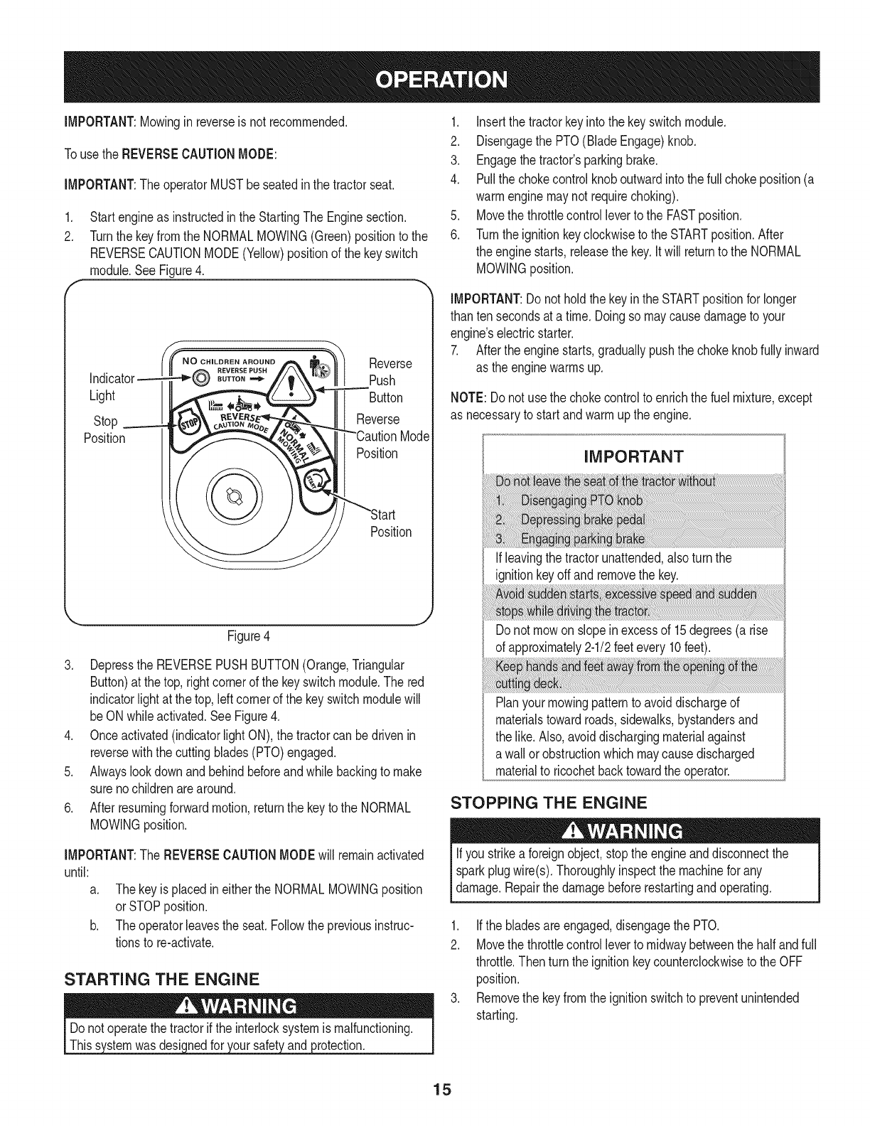
Touse the REVERSECAUTIONMODE:
IMPORTANT:TheoperatorMUSTbe seatedinthe tractorseat.
1. Startengineas instructedinthe StartingThe Enginesection.
2. Turnthe keyfromthe NORMALMOWING(Green)positionto the
REVERSECAUTIONMODE(Yellow)positionof the keyswitch
module.SeeFigure4.
Light
Stop
Position
N OoHILDREN AROUND
BUTTON
Reverse
Push
Button
Reverse
Mode
Position
Position
J
Figure4
3. Depressthe REVERSEPUSHBUTTON(Orange,Triangular
Button)at the top,rightcornerof the keyswitchmodule.The red
indicatorlight at the top,leftcornerof the keyswitchmodulewill
beON whileactivated.SeeFigure4.
4. Onceactivated(indicatorlightON),the tractorcan bedrivenin
reversewiththe cuttingblades(PTO)engaged.
5. Alwayslookdownand behindbeforeandwhilebackingto make
surenochildrenarearound.
6. Afterresumingforwardmotion,returnthe keyto the NORMAL
MOWINGposition.
IMPORTANT:The REVERSECAUTIONMODEwill remainactivated
until:
a. Thekeyis placedin eitherthe NORMALMOWINGposition
orSTOPposition.
b. Theoperatorleavesthe seat.Followthe previousinstruc-
tionsto re-activate.
STARTING THE ENGINE
wasdesic )rotection.
1. Insertthe tractorkeyintothe keyswitchmodule.
2. Disengagethe PTO(BladeEngage)knob.
3. Engagethe tractor'sparkingbrake.
4. Pullthe chokecontrolknoboutwardintothe fullchokeposition(a
warmenginemaynotrequirechoking).
5. Movethe throttlecontrolleverto the FASTposition.
6. Turnthe ignitionkeyclockwiseto the STARTposition.After
the enginestarts, releasethe key.Itwill returnto the NORMAL
MOWINGposition.
IMPORTANT:Do notholdthe keyinthe STARTpositionfor longer
than tensecondsata time. Doingso maycausedamageto your
engine'selectricstarter.
7. Afterthe enginestarts,graduallypushthe chokeknobfully inward
as the enginewarmsup.
NOTE:Donot usethe chokecontrolto enrichthe fuel mixture,except
as necessaryto startandwarmupthe engine.
IMPORTANT
If leavingthe tractorunattended,alsoturn the
ignitionkeyoff and removethe key.
Do not mowon slopeinexcessof 15degrees(a rise
of approximately2-1/2feetevery10feet).
Planyourmowingpatternto avoiddischargeof
materialstowardroads,sidewalks,bystandersand
the like.Also,avoiddischargingmaterialagainst
a wallor obstructionwhichmaycausedischarged
materialto ricochetbacktowardtheoperator.
STOPPING THE ENGINE
Ifyou strikea foreignobject,stopthe engineanddisconnectthe
sparkplugwire(s). Thoroughlyinspectthe machinefor any
damage.Repairthe damagebeforerestartingandoperating.
1. Ifthe bladesareengaged,disengagethe PTO.
2. Movethe throttlecontrolleverto midwaybetweenthe halfandfull
throttle.Thenturn the ignitionkeycounterclockwiseto the OFF
position.
3. Removethe keyfromthe ignitionswitchto preventunintended
starting.
15
DRiViNG THE TRACTOR
iMPORTANT:Avoidsuddenstarts,excessivespeedand sudden
stops.
NOTE:YourRevolutiontractoris equippedwithan innovativedrive
system.Itis normalfor someforwardmovementof thetractorto occur
whenthe brakeis released.
.
2.
Brieflydepressthe brakepedalto releasethe parkingbrake.
Movethe throttleleverintothe FAST(rabbit)position.
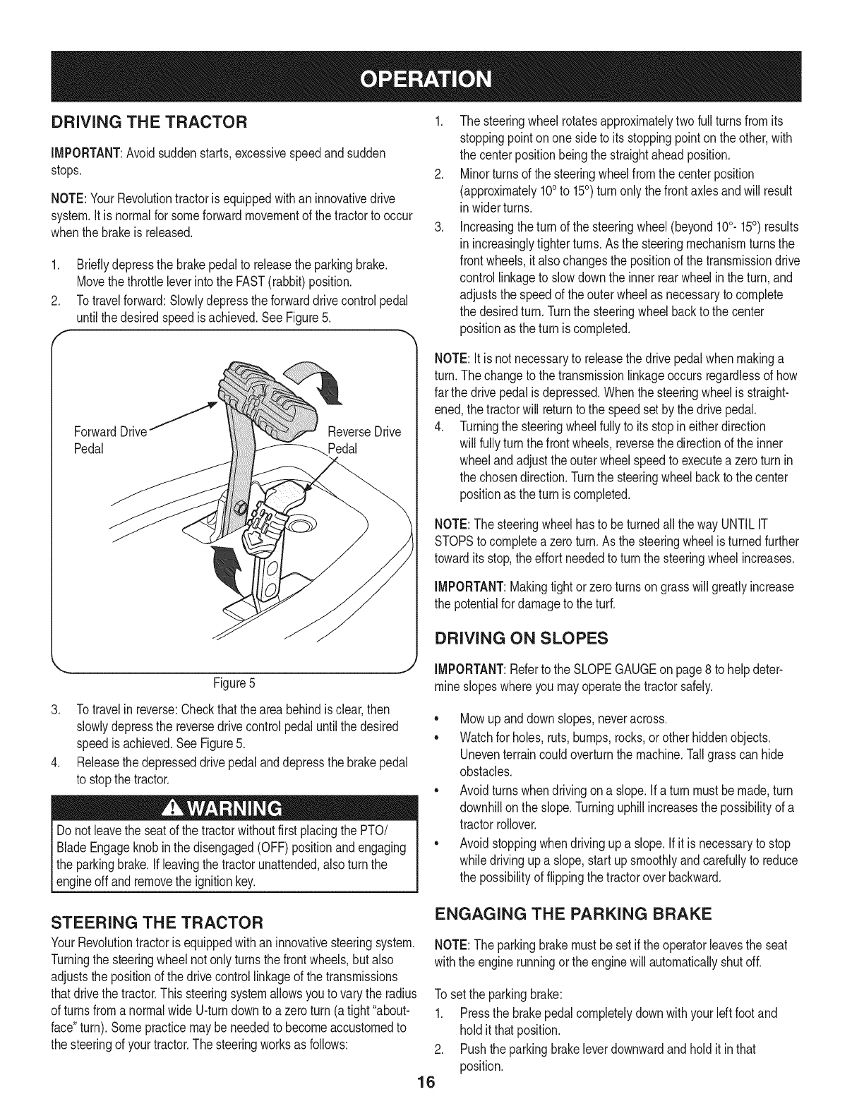
Totravelforward:Slowlydepresstheforwarddrivecontrolpedal
untilthe desiredspeedis achieved.SeeFigure5.
ForwardDrivef
Pedal
Figure5
3. Totravelin reverse:Checkthattheareabehindis clear,then
slowlydepressthe reversedrivecontrolpedaluntilthe desired
speedis achieved.SeeFigure5.
4. Releasethe depresseddrivepedalanddepressthe brakepedal
to stopthe tractor.
Do notleavethe seatof thetractorwithoutfirstplacingthe PTO/
BladeEngageknobin the disengaged(OFF)positionandengaging
the parkingbrake.If leavingthe tractorunattended,also turnthe
_engne offand removethe gnton key.
1. The steeringwheel rotatesapproximatelytwofull turnsfromits
stoppingpointonone sideto its stoppingpointonthe other,with
the centerpositionbeingthe straightaheadposition.
2. Minorturnsof the steeringwheelfromthe centerposition
(approximately100to 150) turnonly the frontaxlesandwill result
in widerturns.
3. Increasingtheturn of the steeringwheel(beyond100.150) results
in increasinglytighterturns.As the steeringmechanismturnsthe
frontwheels,it alsochangesthe positionof thetransmissiondrive
controllinkageto slowdownthe innerrearwheelin theturn,and
adjuststhe speedof theouterwheelas necessaryto complete
the desiredturn.Turnthe steeringwheelbackto the center
positionas the turn is completed.
NOTE: Itis not necessaryto releasethedrive pedalwhenmakinga
turn.Thechangeto the transmissionlinkageoccursregardlessof how
far the drivepedalis depressed.Whenthe steeringwheelis straight-
ened,the tractorwill returnto the speedsetby the drivepedal.
4. Turningthe steeringwheelfullyto its stopineitherdirection
will fullyturnthe frontwheels,reversethe directionof the inner
wheelandadjusttheouterwheelspeedto executea zeroturn in
the chosendirection.Turnthe steeringwheelbackto thecenter
positionas the turn is completed.
NOTE:The steeringwheelhas to beturnedall thewayUNTILIT
STOPSto completea zeroturn.As the steeringwheelis turnedfurther
towardits stop,theeffort neededto turnthe steeringwheelincreases.
IMPORTANT:Makingtightor zeroturnsongrasswill greatlyincrease
the potentialfor damageto theturf.
DRIVING ON SLOPES
IMPORTANT:Referto the SLOPEGAUGEonpage8 to helpdeter-
mine slopeswhereyou mayoperatethe tractorsafely.
• Mowupanddown slopes,neveracross.
• Watchfor holes,ruts,bumps,rocks,orother hiddenobjects.
Uneventerraincouldoverturnthe machine.Tallgrasscan hide
obstacles.
• Avoidturnswhendrivingon a slope,if a turnmustbe made,turn
downhillon the slope.Turninguphillincreasesthe possibilityof a
tractorrollover.
• Avoidstoppingwhendrivingup a slope,if it is necessaryto stop
whiledrivingupa slope,start upsmoothlyandcarefullyto reduce
the possibilityof flippingthe tractoroverbackward.
STEERING THE TRACTOR
YourRevolutiontractoris equippedwithan innovativesteeringsystem.
Turningthe steeringwheelnotonly turnsthe frontwheels,but also
adjuststhe positionof the drivecontrollinkageof thetransmissions
thatdrivethe tractor.Thissteeringsystemallowsyouto varythe radius
of turnsfroma normalwideU-turndownto a zeroturn (a tight"about-
face"turn).Somepracticemaybe neededto becomeaccustomedto
the steeringof yourtractor.The steeringworksas follows:
ENGAGING THE PARKING BRAKE
NOTE:The parkingbrakemustbe setif the operatorleavesthe seat
withthe enginerunningor theenginewill automaticallyshutoff.
To setthe parkingbrake:
1. Pressthe brakepedalcompletelydownwithyour Idt footand
holdit thatposition.
2. Pushthe parkingbrakeleverdownwardandholdit in that
position.
16
3. Removeyourfootfromthe brakepedal.
4. Releasepressurefromthe parkingbrakelever.
Aftercompletingstep3, the brakepedalshouldremainin the down
position.If it doesn't,the parkingbrakeis notengaged.Repeatsteps
1-4to engagethe parkingbrake.
Todisengagethe parkingbrake,lightlypressthe brakepedal.
Neverleavea runningmachineunattended.AlwaysdisengagePTO,
setparkingbrake,stopengineand removekeyto preventunintended
starting.
ENGAGING THE PTO
Engagingthe PTOtransferspowerto the cuttingdeckor other
(separatelyavailable)attachments.Toengagethe PTO:
1. Movethe throttlecontrolleverto the FAST(rabbit)position.
2. Pullthe PTO/BladeEngageknoboutwardintothe engaged(ON)
position.
NOTE:Alwaysoperatethe tractorwiththe throttleleverin the FAST
(rabbit)positionforthe mostefficientuseof the cuttingdeckorother
(separatelyavailable)PTOdrivenattachments.
MOWING
Tohelpavoidbladecontactor a thrownobjectinjury,keepbystand-
ers,helpers,childrenandpetsat least75feetfromthe machine
whileit is inoperation.Stop machineif anyoneentersthearea.
Thistractorisequippedwithoneof Craftsman'shighqualitycutting
decks.The followinginformationwill behelpfulwhenusingthe cutting
deckwithyourtractor.
• Do not mowat highgroundspeed,especiallyif a mulchkitor
grasscollectoris installed.
• For bestresultsit is recommendedthatthe firsttwolaps becut
withthe dischargethrowntowardsthe center.Afterthe first two
laps,reversethe directionto throwthe dischargeto the outside
for the balanceof cutting.Thiswill givea betterappearanceto the
lawn.
• Do notcut thegrasstoo short.Shortgrassinvitesweedgrowth
andyellowsquicklyindry weather.
• Mowingshouldalwaysbedonewiththe engineat full throttle.
• Underheavierconditionsit maybenecessaryto go backoverthe
cutareaa secondtimeto geta cleancut.
• Do notattemptto mowheavybrushandweedsandextremelytall
grass.Yourtractoris designedto mowlawns,notclear brush.
• Keepthe bladessharpandreplacethe bladeswhenworn.Refer
to the "Service& Maintenance"sectionof this manualfor proper
bladesharpeninginstructions.
IMPORTANT:Whenstoppingthe tractorfor anyreasonwhileona
grasssurface,always:
1. Engagethe parkingbrake.
2. Shutengineoffand removethe key.
Doingso will minimizethe possibilityof havingyour lawn"browned"by
hotexhaustfromyourtractor'srunningengine.
MOVING THE TRACTOR MANUALLY
Iffor any reasonthe tractorwill not driveoryou wishto movethe
tractor,engagethetwo transmissionreleaseleversto manuallymove
the tractorshortdistances.
IMPORTANT:Nevertowor dragthetractorwiththe rearwheelsonthe
ground.Evenwiththe releaseleversengaged.Doingso will damage
the transmissions.
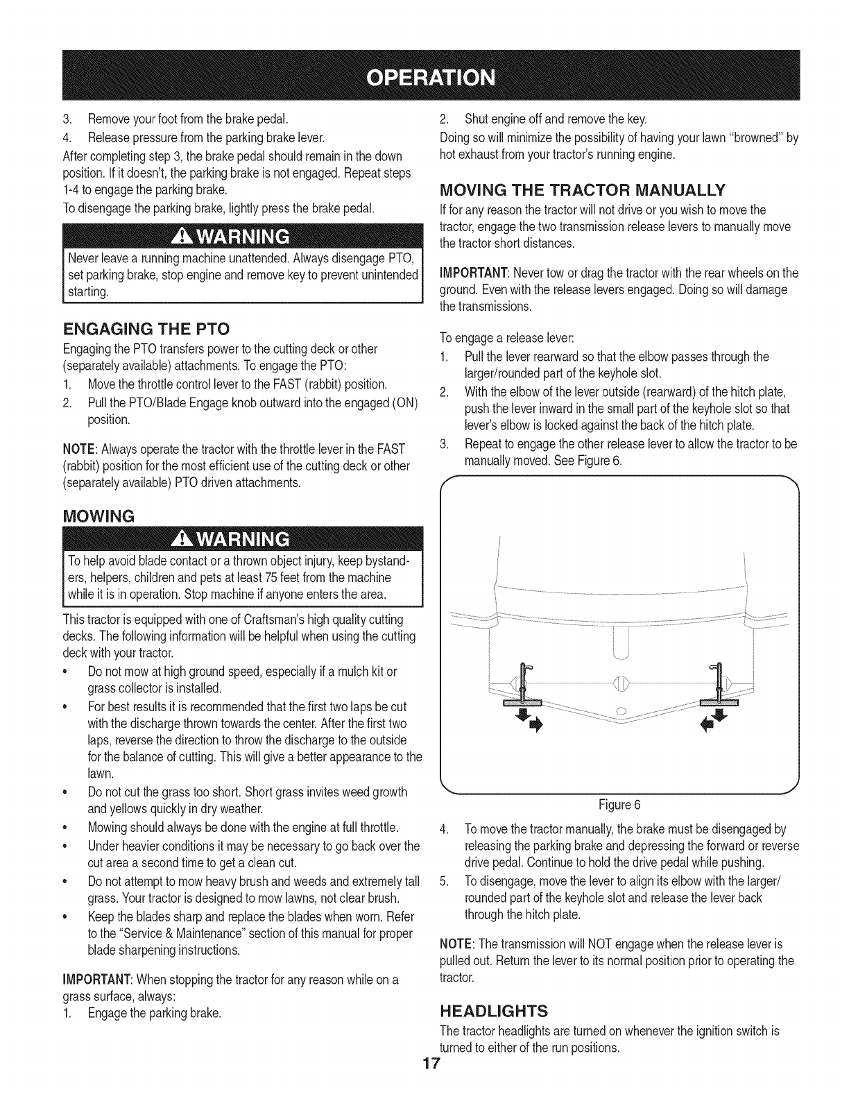
Toengagea releaselever:
1. Pullthe leverrearwardso thatthe elbowpassesthroughthe
larger/roundedpart of the keyholeslot.
2. Withthe elbowof the leveroutside(rearward)of the hitchplate,
pushthe leverinwardinthe smallpartof the keyholeslotso that
lever'selbowis lockedagainstthe backof the hitchplate.
3. Repeatto engagethe otherreleaseleverto allowthe tractorto be
manuallymoved.SeeFigure6.
f
Figure6
4. To movethetractormanually,the brakemustbedisengagedby
releasingthe parkingbrakeanddepressingthe forwardor reverse
drive pedal.Continueto holdthedrive pedalwhilepushing.
5. Todisengage,movethe leverto alignitselbowwiththe larger/
roundedpart of the keyholeslotand releasethe leverback
throughthehitchplate.
NOTE:The transmissionwill NOTengagewhenthe releaseleveris
pulledout.Returnthe leverto itsnormalpositionpriorto operatingthe
tractor.
HEADLIGHTS
The tractorheadlightsare turnedon wheneverthe ignitionswitchis
turnedto eitherof the runpositions.
17
MAINTENANCE SCHEDULE
Beforeperforminganytypeof maintenance/service,disengageall
controlsandstoptheengine.Waituntilallmovingpartshavecometo
acompletestop.Disconnectsparkplugwireandgrounditagainstthe
enginetopreventunintendedstarting.Alwayswearsafetyglassesduring
operationor whileperforminganyadjustmentsor repairs.
Followthe maintenanceschedulegivenbelow.Thischartdescribes
serviceguidelinesonly.Usethe ServiceLogcolumnto keeptrackof
completedmaintenancetasks.To locate the nearest Sears Service
Centeror to scheduleservice,simplycontactSears at
1-800-4-MY-HOME®.
BeforeEachUse
In the FirstFiveHours
Every10Hours
Every25 hours
Every50 hours
Annually
BeforeStorage
1. Engineoil level
2. Mufflerareaandcontrols
3. Fingerguard
1. EngineOil
1. Hood/Dashairvents
2. Batteryterminals
3. Deckspindlesand idler
bracket
1. Air filter'sprecleaner*
2. Air filter*
3. Midsteeringarms,pivot
shafts,andaxles
4. Frontwheelbearings
5. Frontdeckwheels
1. Engineoil/Oil filter
2. Muffler
1. Air filter
2. Air filter'spre-cleaner
3. Sparkplug
4. Air coolingsystem*
5. Fuelfilter
6. SteeringGears
7. RearWheels
1. Hood/Dashairvents
2. Batteryterminals
3. Midsteeringarms,pivot
shafts,andaxles
4. Frontwheelbearings
5. Frontdeckwheels
6. Deckspindlesand idler
bracket
7. Pedalpivotpoints
1. Check
2. Clean
3. Clean
1. Change
1. Clean
2. Clean
3. Lubricate
1. Clean
2. Clean
3. Lubricate
4. Lubricate
5. Lubricate
1. Change/Replace
2. Check
1. Replace
2. Replace
3. Replace
4. Clean
5. Replace
6. Clean
7. Removeandgreaseaxles
1. Clean
2. Clean
3. Lubricate
4. Lubricate
5. Lubricate
6. Lubricate
7. Lubricate
*Servicemorefrequentlyunderdustyconditions.
Beforeperformingany maintenanceor repairs,disengagethe PTO,
engagethe parkingbrake,stopthe engineand removethe keyto
3reventunintendedstarting.
Ifthe enginehasbeen recentlyrun,the engine,mufflerandsur-
roundingmetalsurfaceswill behotand cancauseburnsto the skin.
Exercisecautionto avoidburns.
18
ENGINE MAINTENANCE
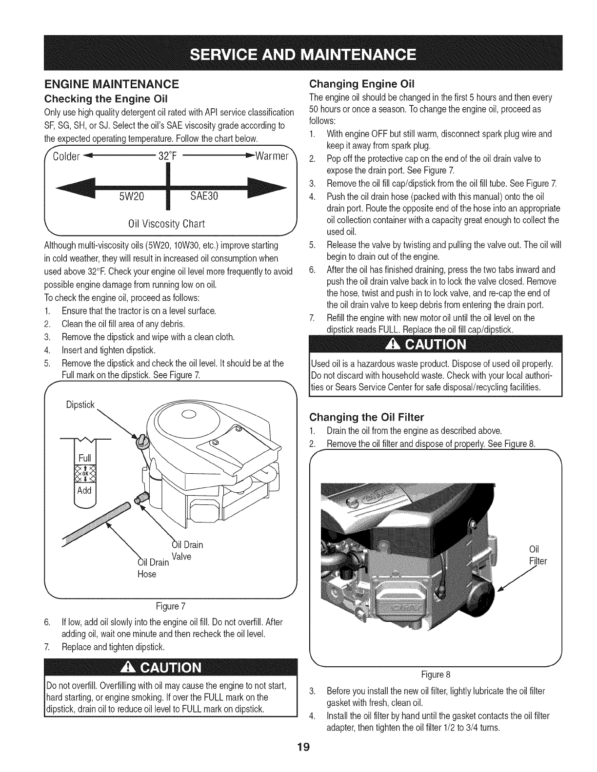
Checking the Engine Oil
Onlyuse highqualitydetergentoil ratedwithAPIserviceclassification
SF,SG,SH,or SJ, Selectthe oil's SAEviscositygradeaccordingto
the expectedoperatingtemperature.Followthe chartbelow.
f_older _ 32°F _Warmer _
Oil Viscosity Chart
Althoughmulti-viscosityoils (5W20,10W30,etc.)improvestarting
in coldweather,theywill resultinincreasedoil consumptionwhen
usedabove32°RCheckyour engineoillevelmorefrequentlyto avoid
possibleenginedamagefromrunninglowonoil.
Tocheckthe engineoil, proceedas follows:
1. Ensurethatthe tractoris ona levelsurface.
2. Cleantheoil fill areaof anydebris.
3. Removethedipstickandwipe withaclean cloth.
4. Insertandtightendipstick.
5. Removethedipstickandcheckthe oil level.It shouldbeat the
Fullmarkonthe dipstick.SeeFigure7.
F
Dipstick
il Drain
Hose
OilDrain
Valve
Figure7
6. If low,addoil slowlyintothe engineoilfill. Do notoverfill.After
addingoil, waitoneminuteand then recheckthe oil level.
7. Replaceandtightendipstick.
Changing Engine Oil
The engineoil shouldbechangedinthe first 5 hoursand thenevery
50 hoursoronce a season.Tochangethe engineoil, proceedas
follows:
1. WithengineOFFbut stillwarm,disconnectsparkplugwireand
keepit awayfromsparkplug.
2. Popoff the protectivecap on theendof the oil drainvalveto
exposethe drainport.SeeFigure7.
3. Removethe oilfill cap/dipstickfromtheoil fill tube.SeeFigure7.
4. Pushthe oil drainhose(packedwiththis manual)ontothe oil
drainport. Routethe oppositeendof the hoseintoan appropriate
oil collectioncontainerwitha capacitygreatenoughto collectthe
usedoil.
5. Releasethe valveby twistingandpullingthe valveout.The oilwill
beginto drainoutof the engine.
6. Afterthe oil hasfinisheddraining,pressthe twotabsinwardand
pushthe oil drainvalvebackinto lockthe valveclosed. Remove
the hose,twist andpushinto lockvalve,and re-capthe endof
the oil drainvalveto keepdebrisfromenteringthe drainport.
7. Refillthe enginewithnewmotoroil untilthe oil levelonthe
dipstickreadsFULL.Replacetheoil fill cap/dipstick.
Usedoil is a hazardouswasteproduct.Disposeof usedoil properly.
IDonot discardwithhouseholdwaste.Checkwithyourlocal authori-
[tiesor SearsServiceCenterfor safedisposal/recyclingfacilities.
Changing the Oil Filter
1. Drainthe oil fromthe engineas describedabove.
2. Removetheoilfilteranddis ure8.
Oil
Filter
Donotoverfill.Overfillingwithoil maycausethe engineto not start,
hardstarting,orenginesmoking.If overthe FULLmarkonthe
dipstick,drainoil to reduceoil levelto FULLmarkondipstick.
19
Figure8
3. Beforeyouinstallthe newoilfilter,lightlylubricatethe oilfilter
gasketwithfresh,cleanoil.
4. Installthe oil filterbyhanduntilthe gasketcontactstheoil filter
adapter,then tightenthe oilfilter 1/2to 3/4 turns.
5. Addoilasdescribedabove.
6. Startandruntheengine.Astheenginewarmsup,checkforoil
leaks.
7. Stoptheengineandchecktheoillevel.ItshouldbeattheFULL
markonthedipstick.
Fuel Filter
3losioncan causesevereburnsor death.
o
1.
.
f
Keepgasolineawayfromsparks,openflames,pilotlights,heat,
andotherignitionsources.
Checkfuel lines,tank,cap,andfittingsfrequentlyforcracksor
leaks.Replaceif necessary.
Beforereplacingthe fuelfilter,drainthe fueltankor closethe fuel
shut-offvalve.
Replacementpartsmustbethe sameand installedin the same
positionas theoriginalparts.
Iffuel spills,waituntil it evaporatesbeforestartingengine.
Beforereplacingthe fuelfilter,drainthe fueltankor closethe fuel
shut-offvalve.Otherwise,fuel can leakout andcausea fire or
explosion.
Usepliersto squeezetabsonthe clamps,then slidethe clamps
awayfromthefuel filter.Twistand pullthefuel linesoff of the fuel
filter.SeeFigure9.
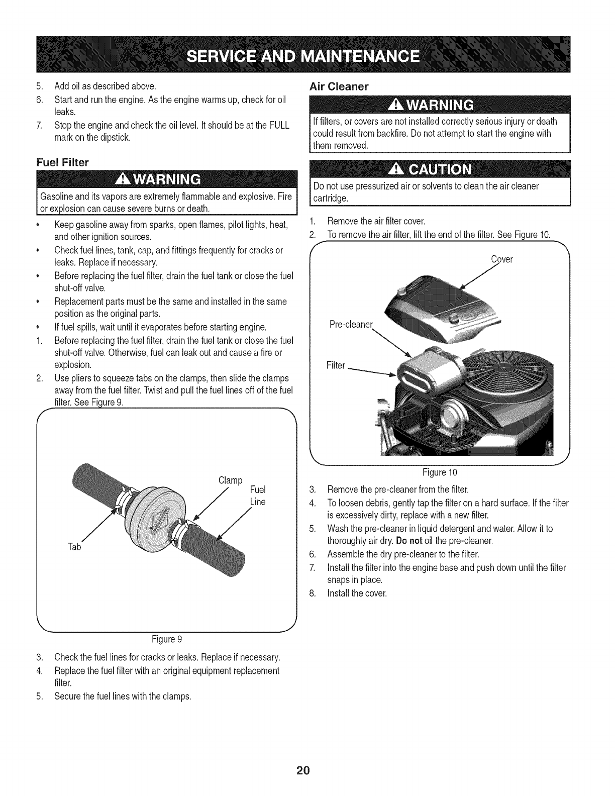
Air Cleaner
Iffilters,or coversare notinstalledcorrectlyseriousinjuryordeath
could resultfrombackfire.Do notattemptto startthe enginewith
themremoved.
Donot use pressurizedair or solventsto cleanthe aircleaner
cartridge.
.
2.
f
Removethe airfiltercover.
To removethe airfilter,liftthe endof thefilter.SeeFigure10.
Cover
Pre-cleaner
Filter
Tab
Clamp Fuel
Line
Figure10
3. Removethe pre-cleanerfromthe filter.
4. To loosendebris,gentlytapthe filteron a hardsurface.If thefilter
is excessivelydirty,replacewitha newfilter.
5. Washthe pre-cleanerinliquiddetergentandwater.Allowit to
thoroughlyair dry.Do not oilthe pre-cleaner.
6. Assemblethe dry pre-cleanerto the filter.
7. Installthe filterintothe enginebaseand pushdown untilthe filter
snapsin place.
8. Installthe cover.
J
Figure9
3. Checkthe fuel linesfor cracksor leaks.Replaceif necessary.
4. Replacethe fuel filterwithan originalequipmentreplacement
filter.
5. Securethe fuel lineswiththe clamps.
2O
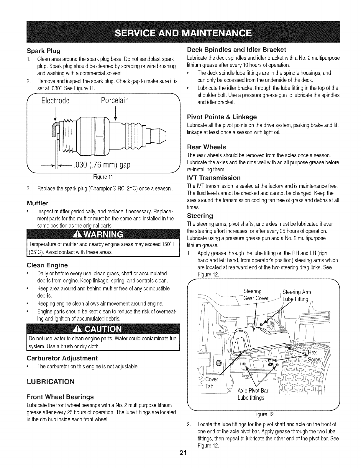
Spark Plug
1. Cleanareaaroundthe sparkplugbase.Do notsandblastspark
plug.Sparkplugshouldbecleanedby scrapingorwire brushing
andwashingwitha commercialsolvent
2. Removeandinspectthe sparkplug.Checkgap to makesureit is
setat .030".See Figure11.
f- -._
Electrode Porcelain
3. Replacethesparkplug(Champion®RC12YC)once a season.
Muffler
o inspectmufflerperiodically,and replaceif necessary.Replace-
mentpartsfor the mufflermustbethe sameand installedin the
same the oric
Temperatureof mufflerand nearbyengineareasmayexceed150° F
(65°0).Avoidcontactwiththeseareas.
Clean Engine
o Dailyor beforeeveryuse,cleangrass,chaff oraccumulated
debrisfromengine.Keeplinkage,spring,andcontrolsclean.
Keepareaaroundandbehindmufflerfreeof any combustible
debris.
Keepingenginecleanallowsair movementaroundengine.
• Enginepartsshouldbe keptcleanto reducethe riskof overheat-
ingandignitionof accumulateddebris.
Donot usewaterto cleanengineparts.Watercouldcontaminatefuel
system.Usea brushordry cloth.
Carburetor Adjustment
Thecarburetoron thisengineis not adjustable.
LUBRICATION
Front Wheel Bearings
Lubricatethe frontwheelbearingswitha No.2 multipurposelithium
greaseafterevery25hoursof operation.The lubefittingsarelocated
in the rimhubinsideeachfrontwheel.
Deck Spindles and Idler Bracket
Lubricatethedeckspindlesandidlerbracketwitha No.2 multipurpose
lithiumgreaseafterevery10hoursof operation.
• The deckspindlelubefittingsareinthe spindlehousings,and
can only beaccessedfromthe undersideof thedeck.
• Lubricatetheidlerbracketthroughthe lubefitting inthe top of the
shoulderbolt.Usea pressuregreasegunto lubricatethe spindles
and idlerbracket.
Pivot Points &Linkage
Lubricateallthe pivotpointsonthe drivesystem,parkingbrakeandlift
linkageat leastonce a seasonwithlightoil.
Rear Wheels
The rearwheelsshouldberemovedfromtheaxlesoncea season.
Lubricatetheaxlesandthe rimswellwithan all purposegreasebefore
re-installingthem.
IVT Transmission
The IVTtransmissionis sealedat the factoryandis maintenancefree.
The fluidlevelcannotbe checkedandcannotbe changed.Keepthe
areaaroundthe transmissioncoolingfan freeof grassanddebrisat all
times.
Steering
The steeringarms, pivotshafts,andaxlesmustbelubricatedif ever
the steeringeffortincreases,or afterevery25 hoursof operation.
Lubricateusinga pressuregreasegunanda No.2 multipurpose
lithiumgrease.
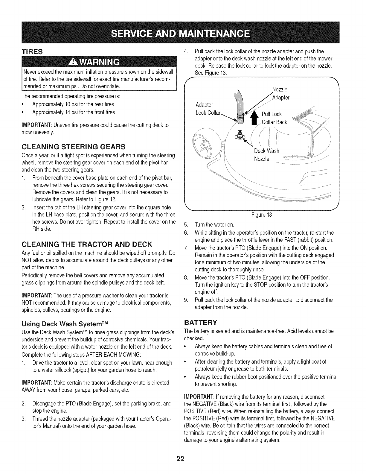
1. Applygreasethroughthe lubefittingonthe RHandLH (right
handandleft hand,fromoperator'sposition)steeringarmswhich
are locatedat rearwardendof the two steeringdraglinks.See
Figure12.
f
Steering SteeringArm
LubeFitting
Tab Axle PivotBar
21
Lubefittings
Figure12
Locatethe lubefittingsforthe pivotshaftandaxle onthe frontof
oneendof theaxle pivotbar.Applygreasethroughthe twolube
fittings,then repeatto lubricatetheother endof the pivotbar.See
Figure12.
TIRES
Neverexceedthe maximuminflationpressureshownont!e sidewall
of tire.Referto the tire sidewallfor exacttire manufacturers recom-
_mendedor maxmumps. Do notovernf ate.
The recommendedoperatingtire pressureis:
• Approximately10psifor the reartires
Approximately14psi for thefronttires
IMPORTANT:Uneventire pressurecouldcausethe cuttingdeckto
mowunevenly.
CLEANING STEERING GEARS
Oncea year,or if a tightspotis experiencedwhenturningthe steering
wheel,removethe steeringgearcoveroneach endof the pivotbar
andcleanthe twosteeringgears.
1. Frombeneaththe coverbaseplateon eachendof the pivotbar,
removethe threehex screwssecuringthe steeringgearcover.
Removethe coversandcleanthe gears.It is not necessaryto
lubricatethe gears.Referto Figure12.
2. Insertthe tabof the LHsteeringgearcoverintothe squarehole
inthe LHbaseplate,positionthe cover,andsecurewiththe three
hexscrews.Donot overtighten.Repeatto installthe coveron the
RHside.
CLEANING THE TRACTOR AND DECK
Anyfuel oroil spilledonthe machineshouldbewipedoff promptly.Do
NOTallowdebristo accumulatearoundthe deckpulleysor anyother
part of the machine.
Periodicallyremovethe beltcoversandremoveany accumulated
grassclippingsfromaroundthe spindlepulleysandthe deckbelt.
IMPORTANT:The useof a pressurewasherto cleanyourtractoris
NOTrecommended,it maycausedamageto electricalcomponents,
spindles,pulleys,bearingsorthe engine.
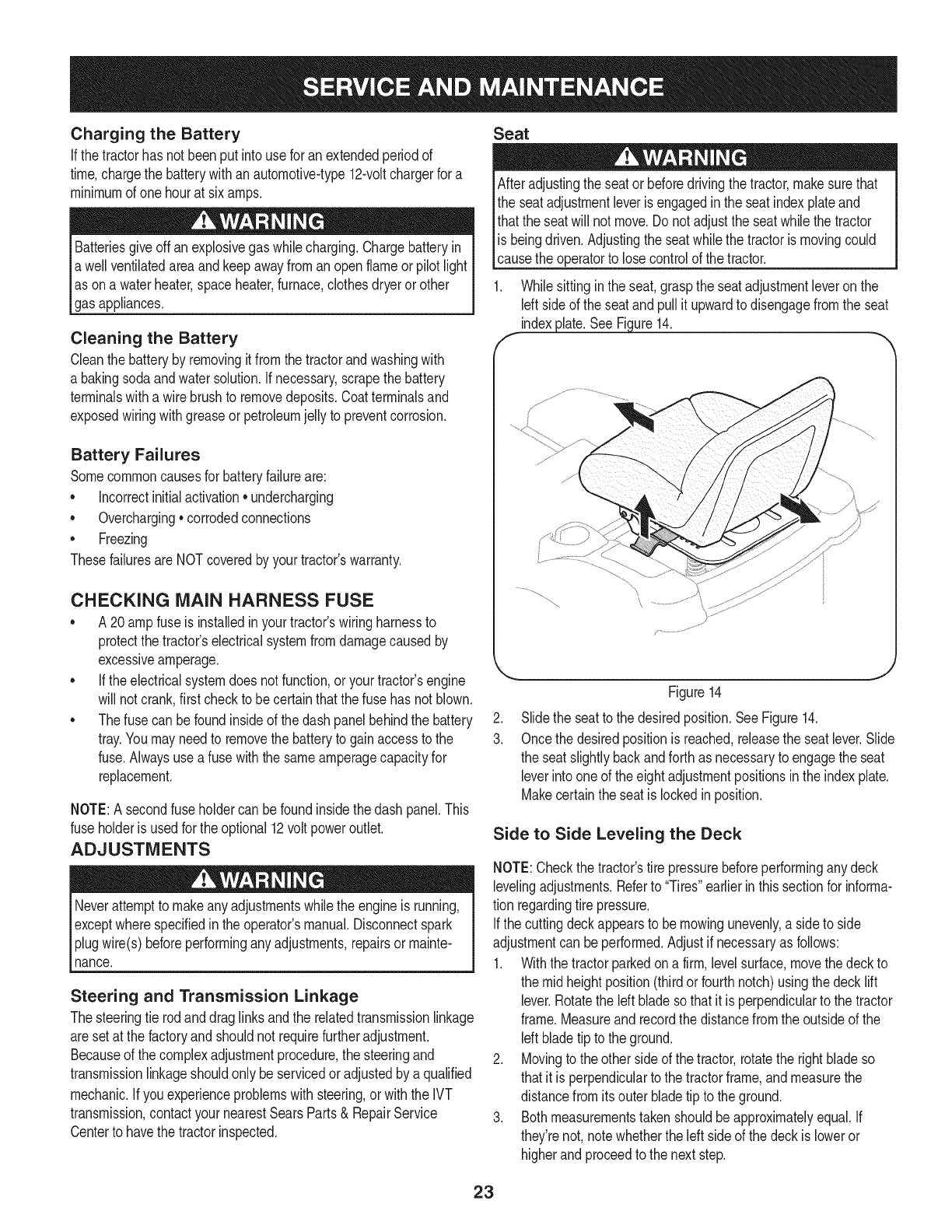
4. Pullbackthe lockcollarof the nozzleadapterandpushthe
adapteronto thedeckwashnozzleat the leftendof the mower
deck. Releasethe lockcollarto lockthe adapteron the nozzle.
See Figure13.
f
Nozzle
Adapter
PullLock
Collar Back
/
/
f,
Deck Wash
Nozzle
Figure13
5. Turnthe wateron.
6. Whilesittingin the operator'spositionon the tractor,re-startthe
engineand placethe throttleleverinthe FAST(rabbit)position.
7. Movethetractor'sPTO(BladeEngage)intothe ON position.
Remainintheoperator'spositionwiththe cuttingdeckengaged
for a minimumof twominutes,allowingthe undersideof the
cuttingdeckto thoroughlyrinse.
8. Movethetractor'sPTO(BladeEngage)intothe OFFposition.
Turnthe ignitionkeyto the STOPpositionto turn the tractor's
engineoff.
9. Pullbackthe lockcollarof the nozzleadapterto disconnectthe
adapterfromthe nozzle.
Using Deck Wash System TM
Usethe DeckWashSystemTM to rinsegrassclippingsfromthe deck's
undersideandpreventthe buildupof corrosivechemicals.Yourtrac-
tor'sdeckis equippedwitha waternozzleonthe leftendof the deck.
Completethe followingstepsAFTEREACHMOWING:
1. Drivethe tractorto a level,clearspotonyour lawn,nearenough
to a watersillcock(spigot)for yourgardenhoseto reach.
IMPORTANT:Makecertainthetractor'sdischargechuteis directed
AWAYfromyourhouse,garage,parkedcars, etc.
2. Disengagethe PTO(BladeEngage),setthe parkingbrake,and
stoptheengine.
3. Threadthe nozzleadapter(packagedwithyourtractor'sOpera-
tot's Manual)ontothe endof yourgardenhose.
BATTERY
The batteryissealedand ismaintenance-free.Acidlevelscannotbe
checked.
Alwayskeepthe batterycablesandterminalscleanandfree of
corrosivebuild-up.
Aftercleaningthe batteryandterminals,applya lightcoatof
petroleumjelly orgreaseto bothterminals.
Alwayskeepthe rubberbootpositionedoverthe positiveterminal
to preventshorting.
IMPORTANT:If removingthe batteryfor any reason,disconnect
the NEGATIVE(Black)wire fromitsterminalfirst, followedby the
POSITIVE(Red)wire.Whenre-installingthe battery,alwaysconnect
the POSITIVE(Red)wire itsterminalfirst,followedby the NEGATIVE
(Black)wire.Becertainthatthe wiresareconnectedto the correct
terminals;reversingthemcouldchangethe polarityandresultin
damageto your engine'salternatingsystem.
22
Charging the Battery
If thetractorhas notbeenput intouse for anextendedperiodof
time,chargethe batterywithanautomotive-type12-voltchargerfor a
minimumof onehourat sixamps.
Batteriesgiveoffan explosivegas whilecharging.Chargebatteryin
awell ventilatedareaandkeepawayfromanopenflameorpilot light
as ona waterheater,spaceheater,furnace,clothesdryerorother
gasappliances.
Cleaning the Battery
Cleanthe batteryby removingitfromthe tractorandwashingwith
a bakingsoda andwatersolution.If necessary,scrapethe battery
terminalswitha wire brushto removedeposits.Coatterminalsand
exposedwiringwithgreaseorpetroleumjellyto preventcorrosion.
Battery Failures
Somecommoncausesfor batteryfailureare:
• Incorrectinitialactivation• undercharging
• Overcharging• corrodedconnections
• Freezing
ThesefailuresareNOTcoveredby yourtractor'swarranty.
CHECKING MAIN HARNESS FUSE
• A 20ampfuseis installedin yourtractor'swiringharnessto
protectthe tractor'selectricalsystemfromdamagecausedby
excessiveamperage.
• If theelectricalsystemdoesnot function,or yourtractor'sengine
will notcrank,first checkto becertainthatthefuse hasnot blown.
• Thefusecan befoundinsideof the dashpanelbehindthe battery
tray.Youmayneedto removethe batteryto gainaccessto the
fuse.Alwaysusea fusewiththe sameamperagecapacityfor
replacement.
NOTE:A secondfuseholdercanbe foundinsidethedash panel.This
fuseholderisusedfor the optional12voltpoweroutlet.
ADJUSTMENTS
Neverattemptto makeanyadjustmentswhilethe engineis running,
exceptwherespecifiedin theoperator'smanual.Disconnectspark
plugwire(s)beforeperforminganyadjustments,repairsor mainte-
nance.
Steering and Transmission Linkage
Thesteeringtie rodanddraglinksandthe relatedtransmissionlinkage
aresetat the factoryandshouldnot requirefurtheradjustment.
Becauseof the complexadjustmentprocedure,the steeringand
transmissionlinkageshouldonlybe servicedor adjustedby a qualified
mechanic.If youexperienceproblemswith steering,or withthe IVT
transmission,contactyournearestSearsParts& RepairService
Centerto havethetractorinspected.
Seat
Afteradjustingthe seator beforedrivingthetractor,makesurethat
the seatadjustmentleveris engagedin the seatindexplateand
thatthe seatwill not move.Do notadjustthe seatwhilethe tractor
is beingdriven.Adjustingthe seatwhilethe tractoris movingcould
causethe operatorto losecontrolof the tractor.
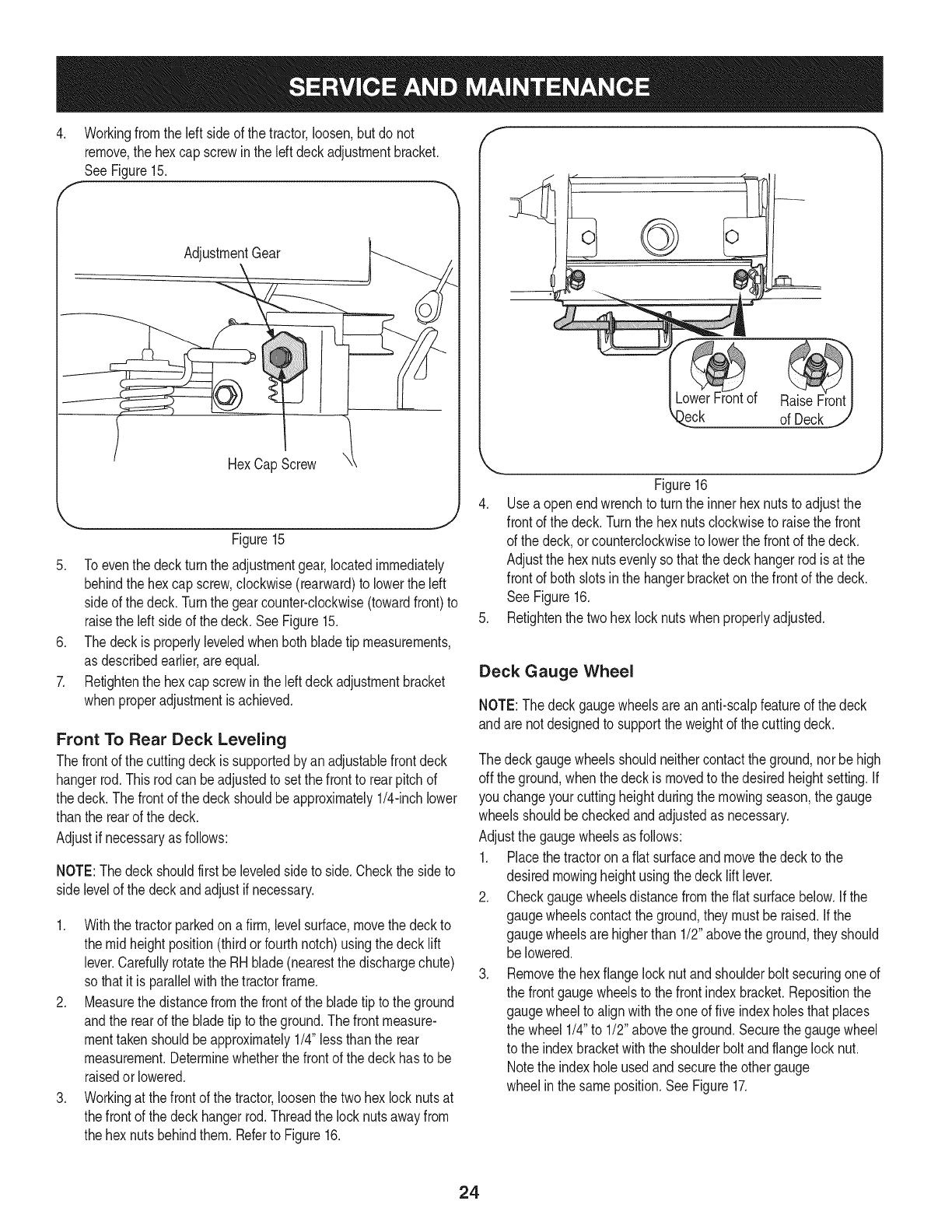
1. Whilesitting inthe seat,graspthe seatadjustmentleveronthe
Idt sideof the seatandpullit upwardto disengagefromthe seat
indexplate.SeeFigure14.
f
Figure14
2. Slidethe seatto thedesiredposition.SeeFigure14.
3. Oncethe desiredpositionis reached,releasetheseatlever.Slide
the seatslightlybackandforthas necessaryto engagetheseat
leverinto oneof theeight adjustmentpositionsinthe indexplate.
Makecertainthe seatis lockedin position.
Side to Side Leveling the Deck
NOTE:Checkthe tractor'stire pressurebeforeperforminganydeck
levelingadjustments.Referto "Tires"earlierinthissectionfor informa-
tion regardingtire pressure.
Ifthe cuttingdeckappearsto be mowingunevenly,a sideto side
adjustmentcan beperformed.Adjustif necessaryas follows:
1. Withthe tractorparkedona firm, levelsurface,movethe deckto
the mid heightposition(thirdorfourthnotch)usingthe decklift
lever.Rotatethe left bladeso thatit is perpendicularto the tractor
frame.Measureand recordthe distancefromthe outsideof the
leftbladetip to the ground.
2. Movingto the otherside of thetractor,rotatethe right bladeso
thatit is perpendiculartothe tractorframe,andmeasurethe
distancefromits outerbladetip to theground.
3. Bothmeasurementstakenshouldbeapproximatelyequal. If
they'renot,notewhetherthe leftside of the deckis loweror
higherandproceedto the nextstep.
23
4. Workingfromthe leftside of the tractor,loosen,but do not
remove,the hexcap screwin the left deckadjustmentbracket.
SeeFigure15.
AdjustmentGear
HexCapScrew
Figure15
5. Toeventhe deckturnthe adjustmentgear,locatedimmediately
behindthe hexcap screw,clockwise(rearward)to lowerthe left
sideof the deck.Turnthe gearcounter-clockwise(towardfront)to
raisethe left sideof the deck.SeeFigure15.
6. Thedeckis properlyleveledwhenbothbladetip measurements,
as describedearlier,areequal.
7. Retightenthe hexcap screwin the leftdeckadjustmentbracket
whenproperadjustmentis achieved.
Front To Rear Deck Leveling
Thefrontof the cuttingdeckissupportedby anadjustablefrontdeck
hangerrod.This rodcanbeadjustedto setthe frontto rearpitchof
thedeck. Thefrontof the deckshouldbeapproximately1/4-inchlower
thanthe rearof the deck.
Adjustif necessaryas follows:
NOTE:Thedeckshouldfirst beleveledsideto side.Checkthe sideto
side levelof the deckandadjustif necessary.
1. Withthe tractorparkedon a firm,levelsurface,movethe deckto
the midheightposition(thirdor fourthnotch)usingthedeck lift
lever.Carefullyrotatethe RHblade(nearestthe dischargechute)
so thatit is parallelwiththe tractorframe.
2. Measurethe distancefromthe frontof the bladetip to the ground
andthe rearof the bladetip to the ground.The frontmeasure-
menttakenshouldbeapproximately1/4"lessthanthe rear
measurement.Determinewhetherthefrontof the deckhasto be
raisedor lowered.
3. Workingat the frontof the tractor,loosenthe twohex locknutsat
thefrontof the deckhangerrod. Threadthe locknutsawayfrom
the hexnutsbehindthem.Referto Figure16.
f
)eck of Deck
Figure16
4. Usea openendwrenchto turnthe innerhexnutsto adjustthe
frontof the deck.Turnthe hexnutsclockwiseto raisethe front
of the deck,or counterclockwiseto lowerthe frontof the deck.
Adjustthe hexnutsevenlysothatthe deckhangerrod isat the
frontof both slotsinthe hangerbracketon the frontof the deck.
See Figure16.
5. Refightenthe twohex locknutswhenproperlyadjusted.
Deck Gauge Wheel
NOTE:The deckgaugewheelsareananti-scalpfeatureof the deck
andare notdesignedto supportthe weightof the cuttingdeck.
The deckgaugewheelsshouldneithercontactthe ground,nor behigh
off the ground,whenthe deckis movedto thedesiredheightsetting.If
you changeyourcuttingheightduringthe mowingseason,the gauge
wheelsshouldbecheckedandadjustedas necessary.
Adjustthe gaugewheelsasfollows:
1. Placethe tractorona fiatsurfaceandmovethe deckto the
desiredmowingheightusingthe decklift lever.
2. Checkgaugewheelsdistancefromthe flat surfacebelow.If the
gaugewheelscontacttheground,theymustbe raised.Ifthe
gaugewheelsare higherthan 1/2"abovethe ground,theyshould
be lowered.
3. Removethe hexflangelocknut andshoulderbolt securingoneof
the frontgaugewheelsto the frontindexbracket.Repositionthe
gaugewheelto alignwiththe oneof fiveindexholesthatplaces
the wheel 1/4"to 1/2" abovethe ground.Securethegaugewheel
to the indexbracketwiththe shoulderbolt andflangelocknut.
Notethe indexholeusedandsecurethe othergauge
wheelin the sameposition.See Figure17.
24
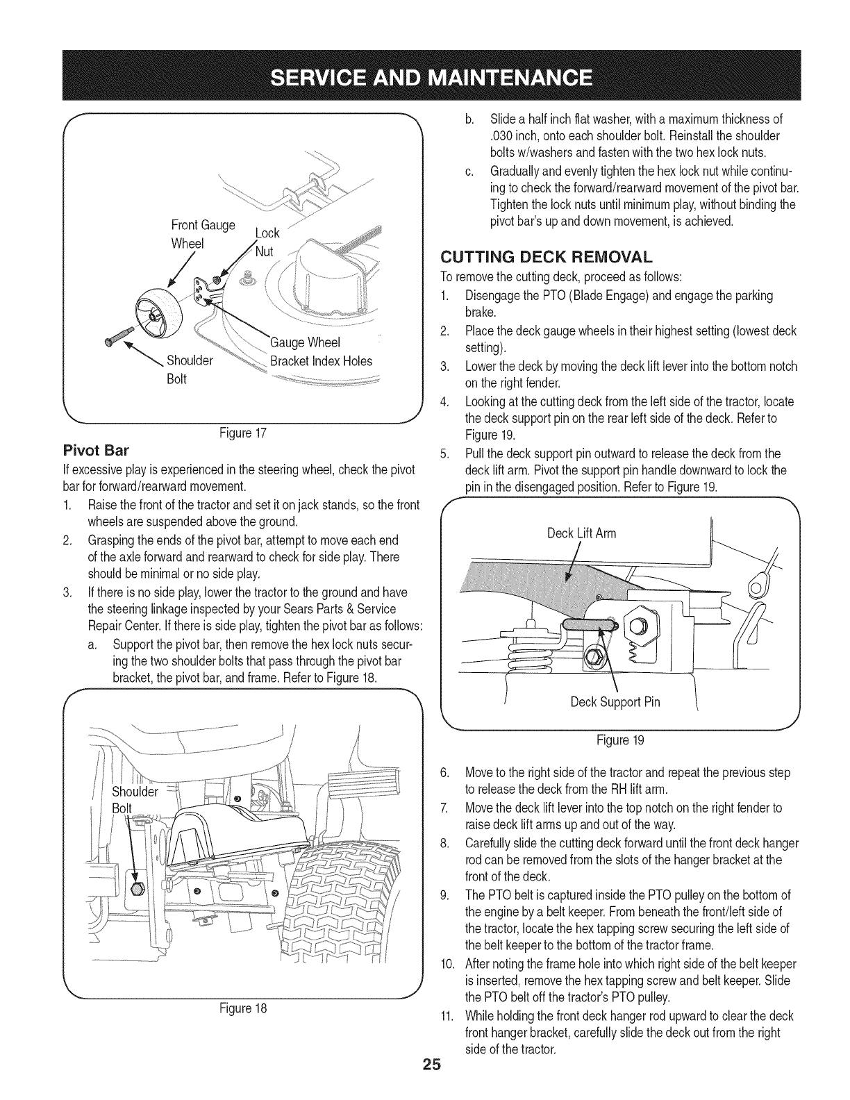
f
FrontGauge Lock ............
Wheel
Wheel
Shoulder BracketIndexHoles
Bolt
'_. j
Figure17
Pivot Bar
If excessiveplay isexperiencedin the steeringwheel,checkthe pivot
barfor forward/rearwardmovement.
1. Raisethe frontof the tractorand setit onjack stands,sothe front
wheelsaresuspendedabovethe ground.
2. Graspingtheends of the pivotbar,attemptto moveeachend
of the axleforwardand rearwardto checkfor side play.There
shouldbeminimalorno sideplay.
3. If thereis no sideplay,lowerthe tractorto the groundandhave
the steeringlinkageinspectedbyyour SearsParts& Service
RepairCenter.Ifthereis sideplay,tightenthe pivotbaras follows:
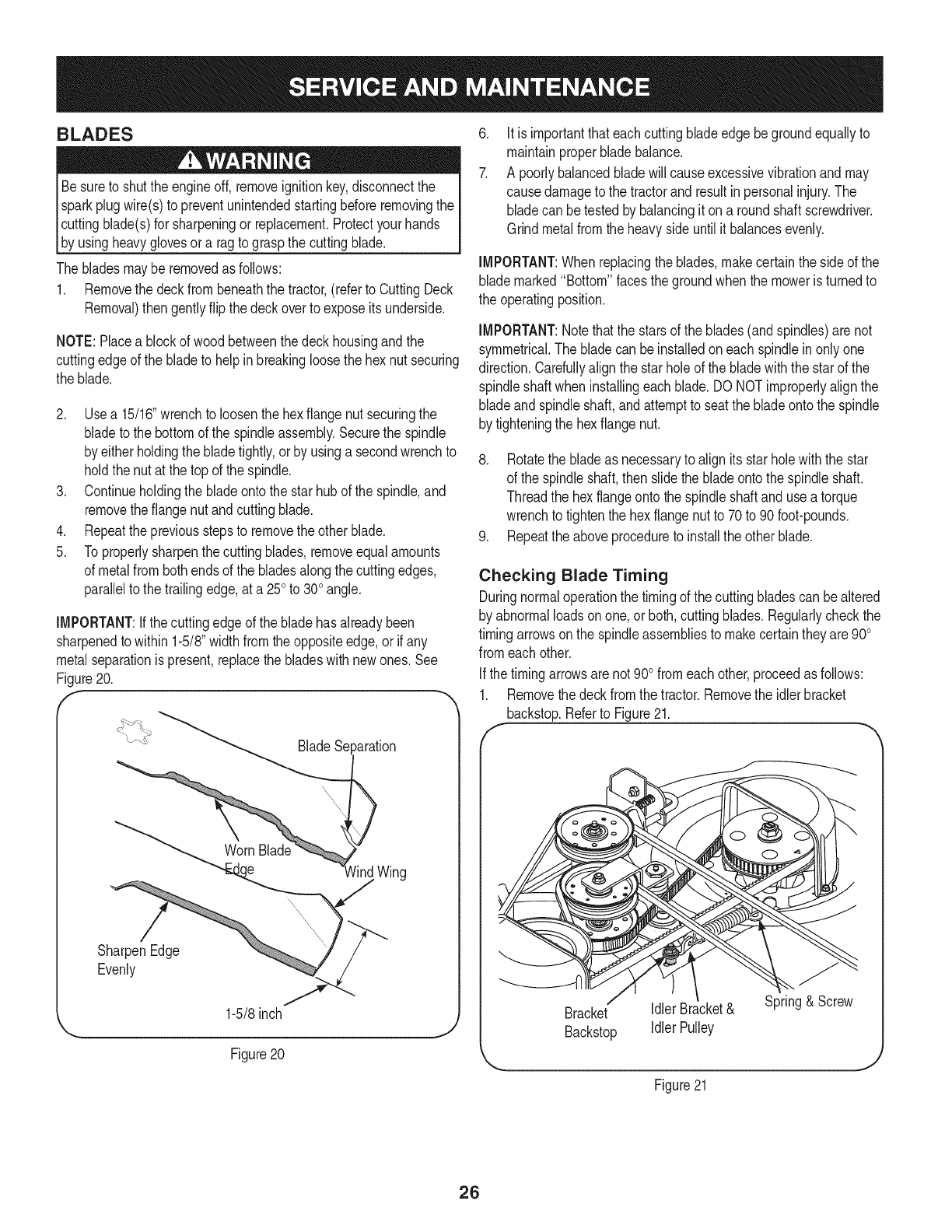
a. Supportthe pivotbar,thenremovethe hexlocknutssecur-
ingthe twoshoulderboltsthatpassthroughthe pivotbar
bracket,the pivotbar,andframe.Referto Figure18.
Figure18
b. Slidea half inchflatwasher,witha maximumthicknessof
.030inch,onto eachshoulderbolt.Reinstallthe shoulder
boltsw/washersandfastenwiththe twohexlock nuts.
c. Graduallyandevenlytightenthe hexlocknut whilecontinu-
ingto checktheforward/rearwardmovementof the pivotbar.
Tightenthe locknutsuntil minimumplay,withoutbindingthe
pivotbar'supanddown movement,is achieved.
CUTTING DECK REMOVAL
To removethe cuttingdeck,proceedas follows:
1. Disengagethe PTO(BladeEngage)andengagethe parking
brake.
2. Placethe deckgaugewheelsin theirhighestsetting(lowestdeck
setting).
3. Lowerthedeck bymovingthe decklift leverintothe bottomnotch
on the rightfender.
4. Lookingat thecuttingdeckfromthe leftside of the tractor,locate
the decksupportpinon the rear leftside of thedeck. Referto
Figure19.
5. Pullthe decksupportpinoutwardto releasethedeckfromthe
decklift arm.Pivotthe supportpin handledownwardto lockthe
pininthe disengagedposition.Referto Figure19.
DeckLiftArm
DeckSupportPin
25
Figure19
6. Moveto the rightsideof the tractorandrepeatthe previousstep
to releasethedeckfromthe RH lift arm.
7. Movethe decklift leverintothe top notchon the rightfenderto
raisedeck liftarmsupandout of the way.
8. Carefullyslidethe cuttingdeckforwarduntilthe frontdeckhanger
rodcan be removedfromthe slotsof the hangerbracketat the
frontof the deck.
9. The PTObelt is capturedinsidethe PTOpulleyonthe bottomof
the engineby a belt keeper.Frombeneaththe front/leftsideof
the tractor,locatethe hextappingscrewsecuringthe leftside of
the belt keeperto the bottomof thetractorframe.
10. Afternotingthe frameholeintowhichright sideof the belt keeper
is inserted,removethe hextappingscrewandbelt keeper.Slide
the PTObelt offthe tractor'sPTOpulley.
11. Whileholdingthe frontdeckhangerrodupwardto clearthe deck
fronthangerbracket,carefullyslidethe deckout fromthe right
sideof the tractor.
BLADES
Besureto shutthe engineoff, removeignitionkey,disconnectthe
sparkplugwire(s)to preventunintendedstartingbeforeremovingthe
cuttingblade(s)for sharpeningor replacement.Protectyourhands
b_ usng heavygovesor a ragto graspthecutt ng bade.
The bladesmayberemovedas follows:
1. Removethe deckfrombeneaththe tractor,(referto CuttingDeck
Removal)then gentlyflip the deckoverto exposeitsunderside.
NOTE:Placea blockof woodbetweenthedeck housingandthe
cuttingedgeof the bladeto helpin breakingloosethehex nut securing
the blade.
2. Usea 15/16"wrenchto loosenthehex flangenutsecuringthe
bladeto the bottomof the spindleassembly.Securethe spindle
by eitherholdingthe bladetightly,orby usinga secondwrenchto
holdthe nutat the top of the spindle.
3. Continueholdingthe bladeontothe starhubof the spindle,and
removethe flangenut andcuttingblade.
4. Repeatthepreviousstepsto removethe otherblade.
5. Toproperlysharpenthe cuttingblades,removeequalamounts
of metalfrombothends of the bladesalongthecuttingedges,
parallelto the trailingedge,at a 250to 300angle.
iMPORTANT:ifthecuttingedgeof the bladehasalreadybeen
sharpenedto within1-5/8"widthfromtheoppositeedge,or if any
metalseparationis present,replacethe bladeswith newones.See
Figure20.
f
_aration
)
lind Wing
SharpenEdge
Evenly
1-5/8inch
Figure 20
.
7.
Itis importantthateach cuttingbladeedgebegroundequallyto
maintainproperbladebalance.
A poorlybalancedbladewill causeexcessivevibrationand may
causedamageto the tractorand resultin personalinjury.The
bladecan betestedby balancingit ona roundshaftscrewdriver.
Grindmetalfromthe heavyside untilit balancesevenly.
iMPORTANT:When replacingthe blades,makecertainthe sideof the
blademarked"Bottom" facesthegroundwhenthe moweris turnedto
the operatingposition.
iMPORTANT:Notethatthe starsof the blades(andspindles)are not
symmetrical.The bladecan beinstalledoneach spindlein onlyone
direction.Carefullyalignthe starholeof thebladewiththe starof the
spindleshaftwheninstallingeachblade.DO NOTimproperlyalignthe
bladeandspindleshaft,andattemptto seatthe bladeontothe spindle
by tighteningthe hexflange nut.
8. Rotatethe bladeas necessaryto alignits starholewiththe star
of the spindleshaft,then slidethe bladeontothe spindleshaft.
Threadthe hexflangeontothe spindleshaft andusea torque
wrenchto tightenthe hex flangenutto 70to 90foot-pounds.
9. Repeatthe aboveprocedureto installthe other blade.
Checking Blade Timing
Duringnormaloperationthe timingof the cuttingbladescan bealtered
by abnormalloadsonone, orboth,cuttingblades.Regularlycheckthe
timingarrowsonthe spindleassembliesto makecertaintheyare900
fromeachother.
Ifthe timingarrowsarenot 900fromeachother,proceedas follows:
1. Removethe deckfromthe tractor.Removethe idlerbracket
backstop.Referto Figure21.
f
Bracket Idler Bracket& Spring& Screw
Backstop Idler Pulley
Figure21
26
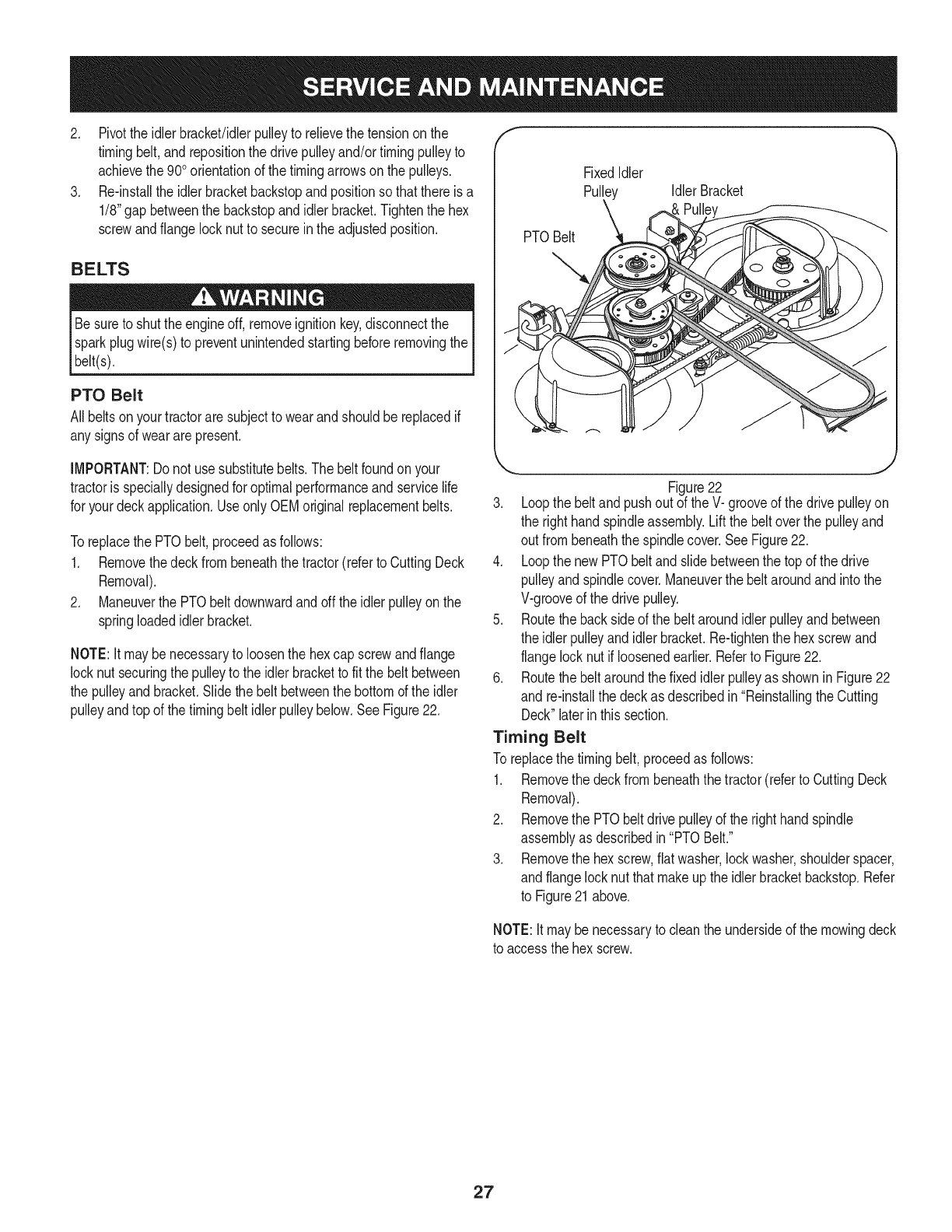
2. Pivotthe idlerbracket/idlerpulleyto relievethe tensiononthe
timingbelt,and repositionthe drivepulleyand/or timingpulleyto
achievethe 900orientationof the timingarrowsonthe pulleys.
3. Re-installthe idlerbracketbackstopandpositionso thatthereis a
1/8"gapbetweenthe backstopandidlerbracket.Tightenthe hex
screwandflange locknutto secureinthe adjustedposition.
BELTS
Besureto shutthe engineoff, removeignitionkey,disconnectthe
sparkplugwire(s)to preventunintendedstartingbeforeremovingthe
belt(s).
PTO Belt
Allbeltsonyour tractorare subjectto wearandshouldbe replacedif
anysignsof weararepresent.
f
PTOBelt
FixedIdler
Pulley Idler Bracket
IMPORTANT:Do not usesubstitutebelts.Thebelt foundonyour
tractoris speciallydesignedfor optimalperformanceandservicelife
for yourdeckapplication.Useonly OEMoriginalreplacementbelts.
Toreplacethe PTObelt,proceedas follows:
1. Removethedeckfrombeneaththe tractor(referto CuttingDeck
Removal).
2. Maneuverthe PTObeltdownwardandoffthe idlerpulleyonthe
springloadedidlerbracket.
NOTE:It maybe necessaryto loosenthe hexcap screwandflange
locknut securingthe pulleyto the idlerbracketto fitthe beltbetween
the pulleyand bracket.Slidethe beltbetweenthe bottomof the idler
pulleyandtop of the timingbeltidlerpulleybelow.SeeFigure22.
,,, j
Figure22
3. Loopthe beltand pushout of theV- grooveof the drivepulleyon
the right handspindleassembly.Liftthe belt overthe pulleyand
out frombeneaththe spindlecover.SeeFigure22.
4. Loopthe newPTObelt andslidebetweenthe topof the drive
pulleyandspindlecover.Maneuverthe beltaroundandintothe
V-grooveof the drivepulley.
5. Routethebacksideof the beltaroundidlerpulleyandbetween
the idlerpulleyandidlerbracket.Re-tightenthe hexscrewand
flangelock nutif loosenedearlier.Referto Figure22.
6. Routethebelt aroundthe fixedidlerpulleyas shownin Figure22
and re-installthe deckas describedin "Reinstallingthe Cutting
Deck"laterinthis section.
Timing Belt
To replacethe timingbelt,proceedas follows:
1. Removethe deckfrombeneaththe tractor(referto CuttingDeck
Removal).
2. Removethe PTObeltdrive pulleyof the righthandspindle
assemblyas describedin "PTOBelt."
3. Removethe hexscrew,flatwasher,lockwasher,shoulderspacer,
andflangelocknut thatmakeup the idlerbracketbackstop.Refer
to Figure21above.
NOTE:Itmaybenecessaryto cleanthe undersideof the mowingdeck
to accessthehex screw.
27
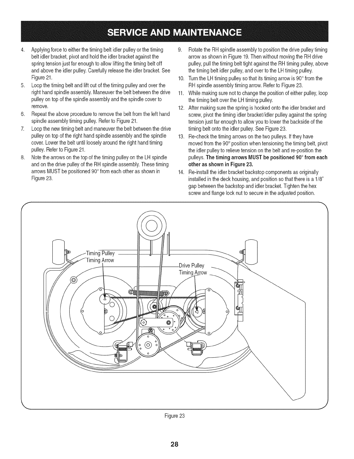
4. Applyingforceto eitherthetimingbelt idlerpulleyor thetiming
belt idlerbracket,pivotand holdtheidlerbracketagainstthe
springtensionjust farenoughto allowliftingthe timingbeltoff
andabovethe idlerpulley.Carefullyreleasethe idlerbracket.See
Figure21.
5. Loopthe timingbeltandlift out of the timingpulleyandoverthe
righthandspindleassembly.Maneuverthe belt betweenthe drive
pulleyontop of the spindleassemblyandthe spindlecoverto
remove.
6. Repeattheaboveprocedureto removethe beltfromthe left hand
spindleassemblytimingpulley.Referto Figure21.
7. Loopthe newtimingbeltand maneuverthe belt betweenthe drive
pulleyontop of the righthandspindleassemblyandthe spindle
cover.Lowerthe belt until looselyaroundthe right handtiming
pulley.Referto Figure21.
8. Notethe arrowson thetop of the timingpulleyonthe LHspindle
andonthe drivepulleyof the RHspindleassembly.Thesetiming
arrowsMUSTbe positioned90ofromeach otheras shownin
Figure23.
9. Rotatethe RHspindleassemblyto positionthedrive pulleytiming
arrowas shownin Figure19.Then withoutmovingthe RHdrive
pulley,pullthe timingbelt tightagainstthe RHtimingpulley,above
the timingbeltidlerpulley,andover to the LHtimingpulley.
10. Turnthe LHtimingpulleysothat itstimingarrowis 900fromthe
RHspindleassemblytimingarrow.Referto Figure23.
11. Whilemakingsure notto changethe positionof either pulley,loop
the timingbeltoverthe LH timingpulley.
12. Aftermakingsurethe springis hookedonto the idlerbracketand
screw,pivotthetimingidlerbracket!idlerpulleyagainstthe spring
tensionjustfar enoughto allowyouto lowerthe backsideof the
timingbeltonto theidlerpulley.SeeFigure23.
13. Re-checkthe timingarrowsonthe twopulleys.Iftheyhave
movedfromthe900positionwhentensioningthe timingbelt,pivot
the idlerpulleyto relievetensiononthe beltand re-positionthe
pulleys.Thetiming arrows MUSTbe positioned900from each
other as shownin Figure23.
14. Re-installthe idlerbracketbackstopcomponentsas originally
installedin thedeck housing,andpositionso thatthereis a 1/8"
gap betweenthe backstopandidler bracket.Tightenthe hex
screwandflangelocknut to securein theadjustedposition.
Pulley
Arrow
@
Pulley
TimingArrow
Figure23
28
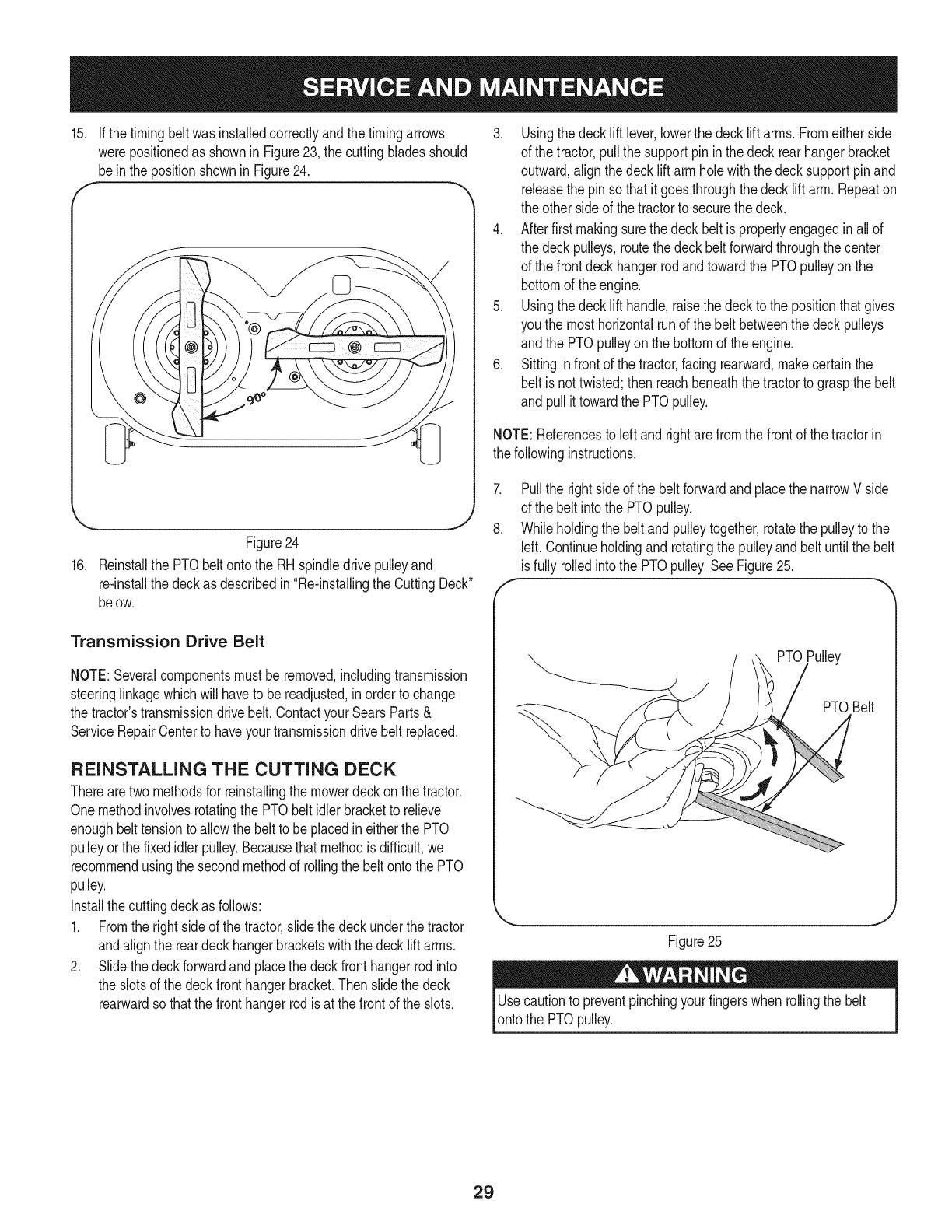
15. If thetimingbeltwasinstalledcorrectlyandthetimingarrows
werepositionedas shownin Figure23, the cuttingbladesshould
bein the positionshownin Figure24.
-.. J
Figure24
16. Reinstallthe PTObeltontothe RHspindledrivepulleyand
re-installthe deckas describedin"Re-installingthe CuttingDeck"
below.
Transmission Drive Belt
NOTE:Severalcomponentsmustbe removed,includingtransmission
steeringlinkagewhichwill haveto be readjusted,inorderto change
the tractor'stransmissiondrivebelt.ContactyourSearsParts&
ServiceRepairCenterto haveyourtransmissiondrive belt replaced.
REINSTALLING THE CUTTING DECK
Therearetwomethodsfor reinstallingthemowerdeckon thetractor.
Onemethodinvolvesrotatingthe PTObelt idlerbracketto relieve
enoughbelttensionto allowthe belt to beplacedin eitherthe PTO
pulleyor the fixedidlerpulley.Becausethat methodis difficult,we
recommendusingthe secondmethodof rollingthe beltonto the PTO
pulley.
Installthecuttingdeckas follows:
1. Fromthe rightside of the tractor,slide thedeckunderthetractor
andalignthe reardeckhangerbracketswith thedecklift arms.
2. Slidethedeckforwardandplacethe deckfronthangerrodinto
the slotsof the deckfronthangerbracket.Thenslidethe deck
rearwardso thatthefronthangerrodis at thefrontof the slots.
3. Usingthedecklift lever,lowerthe deck liftarms.Fromeitherside
of the tractor,pullthe supportpinin the deck rearhangerbracket
outward,alignthe deckliftarm holewiththe decksupportpinand
releasethe pinso thatit goesthroughthedeck liftarm.Repeaton
the otherside of thetractorto securethe deck.
4. Afterfirst makingsurethe deckbeltis properlyengagedin allof
the deckpulleys,routethe deckbeltforwardthroughthe center
of the frontdeckhangerrodandtowardthe PTOpulleyon the
bottomof the engine.
5. Usingthedecklift handle,raisethe deckto the positionthatgives
you the mosthorizontalrunof the belt betweenthe deckpulleys
andthe PTOpulleyonthe bottomof the engine.
6. Sittinginfrontof the tractor,facingrearward,makecertainthe
beltis not twisted;thenreachbeneaththe tractorto graspthe belt
and pullit towardthe PTOpulley.
NOTE:Referencesto leftand rightare fromthe frontof the tractorin
the followinginstructions.
7.
8.
Pullthe rightsideof the beltforwardand placethe narrowV side
of the belt intothe PTOpulley.
Whileholdingthe belt andpulleytogether,rotatethe pulleyto the
Idt. Continueholdingand rotatingthe pulleyandbelt untilthe belt
isfully rolledintothe PTOpulley.SeeFigure25.
PTOPulley
PTOBelt
J
Figure25
Usecautionto preventpinchingyourfingerswhen rollingthe belt
ontothe PTOpulley.
29
Neverstorelawntractorwithfuel intankindoorsor in poorly
ventilatedareaswherefuel fumesmayreachan openflame,spark,
or pilot lightas ona furnace,waterheater,clothesdryer,or gas
appliance.
PREPARING THE ENGINE
iMPORTANT:Fuelleftinthe fueltankduringwarmweatherdeterio-
ratesandwillcauseseriousstartingproblems.
Gasolineisa toxic substance.Disposeof gasolineproperly.Contact
your localauthoritiesfor approveddisposalmethods.
To preventgumdepositsfromforminginsidethe engine'scarburetor
andcausingpossiblemalfunctionof theengine,the fuelsystemmust
be eithercompletelyemptied,or the gasolinemustbetreatedwitha
stabilizerto preventdeterioration.
1. Ifusinga fuel stabilizer:
• Readthe productmanufacturer'sinstructionsandrecommenda-
tions.
• Addto clean,freshgasolinethe correctamountof stabilizerfor
the capacityof the fuel system.
• Fillthe fueltankwithtreatedfuel andrunthe enginefor 2-3
minutesto get stabilizedfuel intothe carburetor.
2. Ifemptyingthe fuel system:
• Donot drainfuelwhenthe engineis hot.Allowthe engine
adequatetimeto cool.Drainfuelinto anapprovedcontainer
outdoors,awayfromopenflame.
• Drainany largevolumeof fuel fromthetankby disconnectingthe
fuel linefrom the in-linefuelfilter nearthe engine.
Gasolineis extremelyflammableandcan beexplosiveundercertain
conditions.Draingasolinebeforestoringthe equipmentfor extended
periods.Drainfuelonly intoan approvedcontaineroutdoors,away
fromanopenflame.Allow engineto cool.Extinguishcigarettes,
cigars,pipes,andothersourcesof ignitionpriorto drainingfuel.
Storegasolinein anapprovedcontainerin safelocation.
• Reconnectthe fuel lineandrunthe engineuntil it startsto falter,
then usethe choketo keepthe enginerunninguntil allfuel inthe
carburetorhas beenexhausted.
• Againdisconnectthefuel lineanddrainany remaininggasoline
fromthe system.
3. Removethe sparkplugandpourone(1)ounceof engineoil
throughthe sparkplugholeintothe cylinder.Crankthe engine
severaltimesto distributethe oil. Replacethe sparkplug.
PREPARING THE LAWN TRACTOR
• Cleanandlubricatetractorthoroughlyas describedinthe lubrica-
tion instructions.
• Donot usea pressurewasheror gardenhoseto cleanyour unit.
Store mowerin a dry,cleanarea. Do notstorenextto corrosive
materials,suchas fertilizer.
30
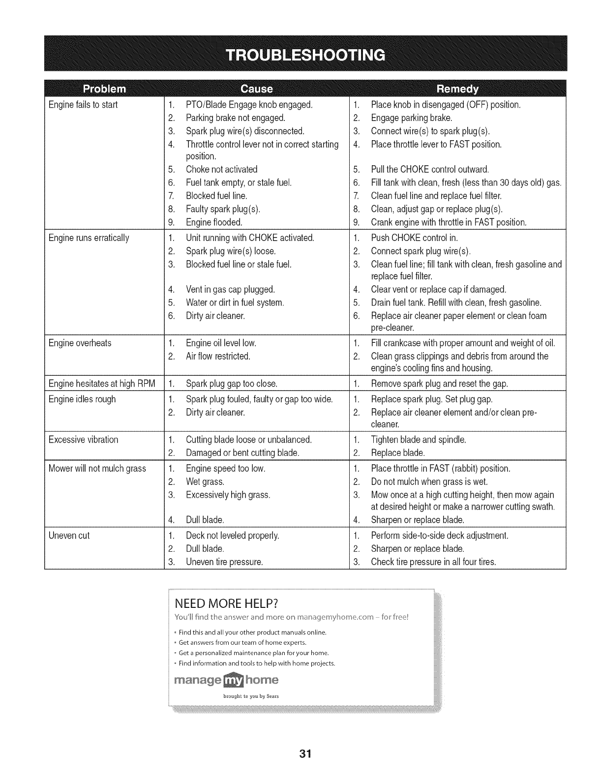
Enginefailsto start
Enginerunserratically
1. PTO/BladeEngageknobengaged.
2. Parkingbrakenotengaged.
3. Sparkplugwire(s)disconnected.
4. Throttlecontrollevernot incorrectstarting
position.
5. Chokenotactivated
6. Fueltankempty,or stalefuel.
7. Blockedfuel line.
8. Faultysparkplug(s).
9. Engineflooded.
1. Unitrunningwith CHOKEactivated.
2. Sparkplugwire(s)loose.
3. Blockedfuel lineor stalefuel.
4. Ventingas cap plugged.
5. Wateror dirt in fuel system.
6. Dirtyair cleaner.
Engineoverheats 1. Engineoil levellow. 1.
2. Airflowrestricted. 2.
Enginehesitatesat high RPM 1. Sparkpluggaptoo close. 1.
Engineidles rough 1. Sparkplugfouled,faultyor gaptoo wide. 1.
2. Dirtyair cleaner. 2.
Excessivevibration
Mowerwill not mulchgrass
Unevencut
1. Cuttingbladelooseor unbalanced.
2. Damagedorbent cuttingblade.
1. Enginespeedtoo low.
2. Wetgrass.
3. Excessivelyhighgrass.
4. Dullblade.
1. Decknot leveledproperly.
2. Dullblade.
3. Uneventire pressure.
1. Placeknobindisengaged(OFF)position.
2. Engageparkingbrake.
3. Connectwire(s)to sparkplug(s).
4. Placethrottleleverto FASTposition.
5. Pullthe CHOKEcontroloutward.
6. Filltankwithclean,fresh(lessthan 30daysold)gas.
7. Cleanfuel lineand replacefuelfilter.
8. Clean,adjustgapor replaceplug(s).
9. Crankenginewiththrottlein FASTposition.
1. PushCHOKEcontrolin.
2. Connectsparkplugwire(s).
3. Cleanfuel line; fill tankwithclean,freshgasolineand
replacefuel filter.
4. Clearventor replacecap if damaged.
5. Drainfueltank. Refillwithclean,freshgasoline.
6. Replaceair cleanerpaperelementor cleanfoam
pre-cleaner.
Fillcrankcasewithproperamountandweightof oil.
Cleangrassclippingsanddebrisfromaroundthe
engine'scoolingfinsandhousing.
Removesparkplugandresetthe gap.
Replacesparkplug.Set pluggap.
Replaceair cleanerelementand/orcleanpre-
cleaner.
1. Tightenbladeandspindle.
2. Replaceblade.
1. Placethrottlein FAST(rabbit)position.
2. Do notmulchwhen grassis wet.
3. Mowonceat a highcuttingheight,then mowagain
at desiredheightor makea narrowercuttingswath.
4. Sharpenor replaceblade.
1. Performside-to-sidedeckadjustment.
2. Sharpenor replaceblade.
3. Checktire pressureinall fourtires.
NEED MORE HELP?
Youll fkld t_e answe_ _"ct mo_e o_ maoage_nyl]o_ne co_n - br kee!
Find this and all your other product manuals online.
Get answers from our team of home experts.
,, Get a personalized maintenance plan for your home.
,, Find information and tools to help with home projects.
maoage _ home
b_*oug_t t_ _'ou by Sea_'s
31
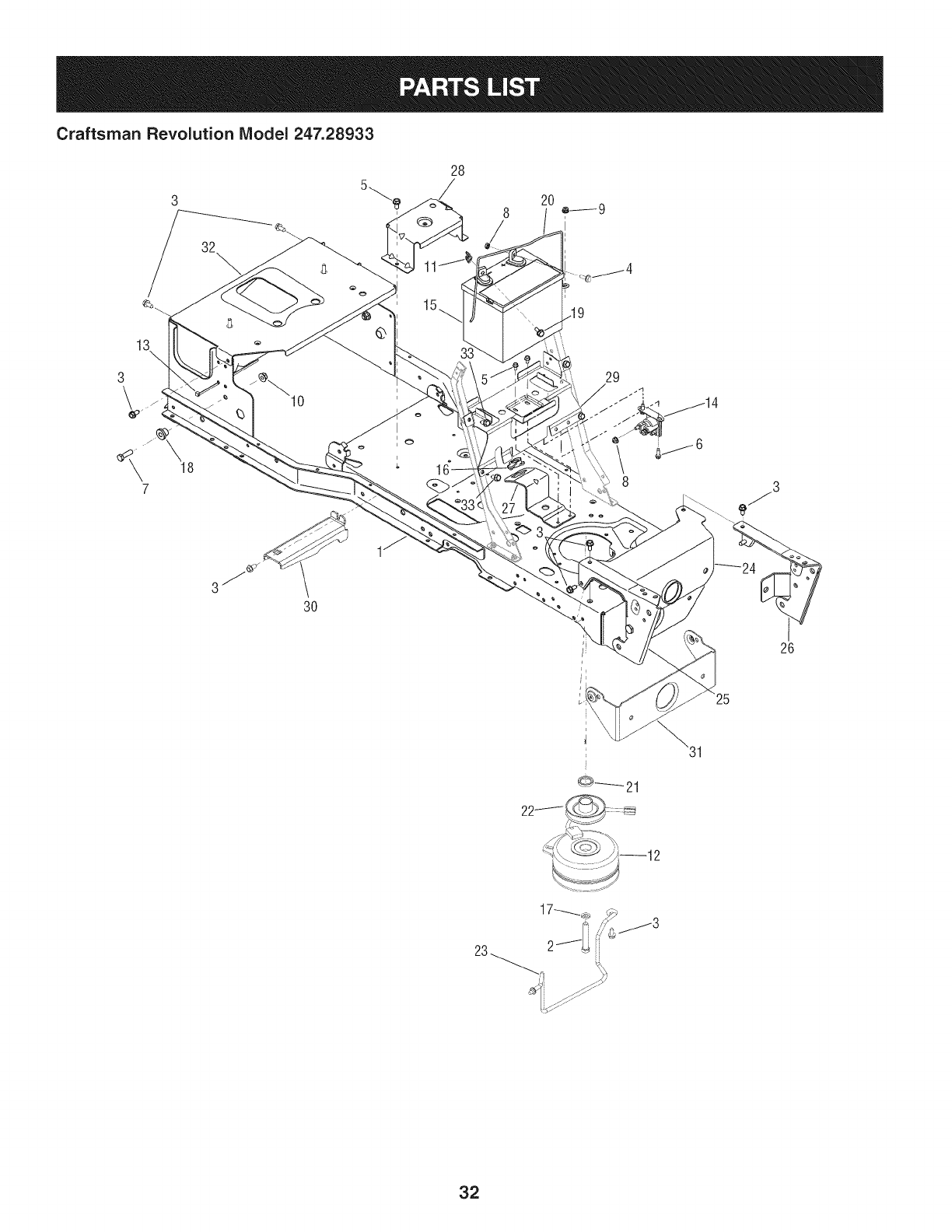
Craftsman Revolution Model 247.28933
28
3
\
32\
13 3:
19
29
7
3O
26
25
0------_21
23
32

Craftsman Revolution IViodel 247.28933
D = O O
683-04269-0637 FrameAssembly
2. 710-04377 Screw,HexCap Lock,7/16-20x 2.75
3. 710-04484 Screw,HexWash.,5/16-18x .75
4. 710-04666 Screw,HexFlangeHd., 1/4-20x .75
5. 710-0599 Screw,HexWash.,1/4-20x .5
6. 710-0642 Screw,HexWash.,1/4-20x .75
7. 710-3005 Screw,HexCap,3/8-16x 1.25Gr5
8. 712-0271 Nut, HexSeres,1/4-20
9. 712-04064 Nut, HexFlangeInsertLock,1/4-20
10. 712-04065 Nut, HexFlangeinsertLock,3/8-16
11. 712-3087 Nut,Wing,1/4-20
12. 917-04526 Clutch,ElectricPTO
13. 725-0157 CableTie
14. 725-04439 Solenoid,Start
15. 925-1707D Battery
16. 731-05659 Bushing,SteeringShaft
17. 936-0171 Washer,Lock,7/16
18. 738-04058 Spacer,Shoulder,.38x 1.0x .7
19. 738-1132 Screw,Shoulder,.25x.15:1/4-20
20. 747-04215-0637 Strap,Battery
21. 750-04763 Spacer,1.37x 1.00x .25
22. 756-04354 Pulley,Engine
23. 747-05056 Rod,BeltKeeper
24. 783-04806-0637 Bracket,PivotBar
25. 783-04844-0637 Bracket,PivotSupportRH
26. 783-04845-0637 Bracket,PivotSupportLH
27. 783-04868-0637 Bracket,SteeringSupport
28. 783-04910A-0637 Bracket,SupportFender
29. 783-05469-0637 Bracket,BatterySupport
30. 783-05617B-0637 Bracket,RunningBoardSupport- LH
783-06193-0637 Bracket,RunningBoardSupport- RH
31. 783-05760-0637 Bracket,PivotBarSupport
32. 783-05850-0637 Plate,SeatFrame
33. 710-04484 Screw,HexWash.,5/16-18x .75
33
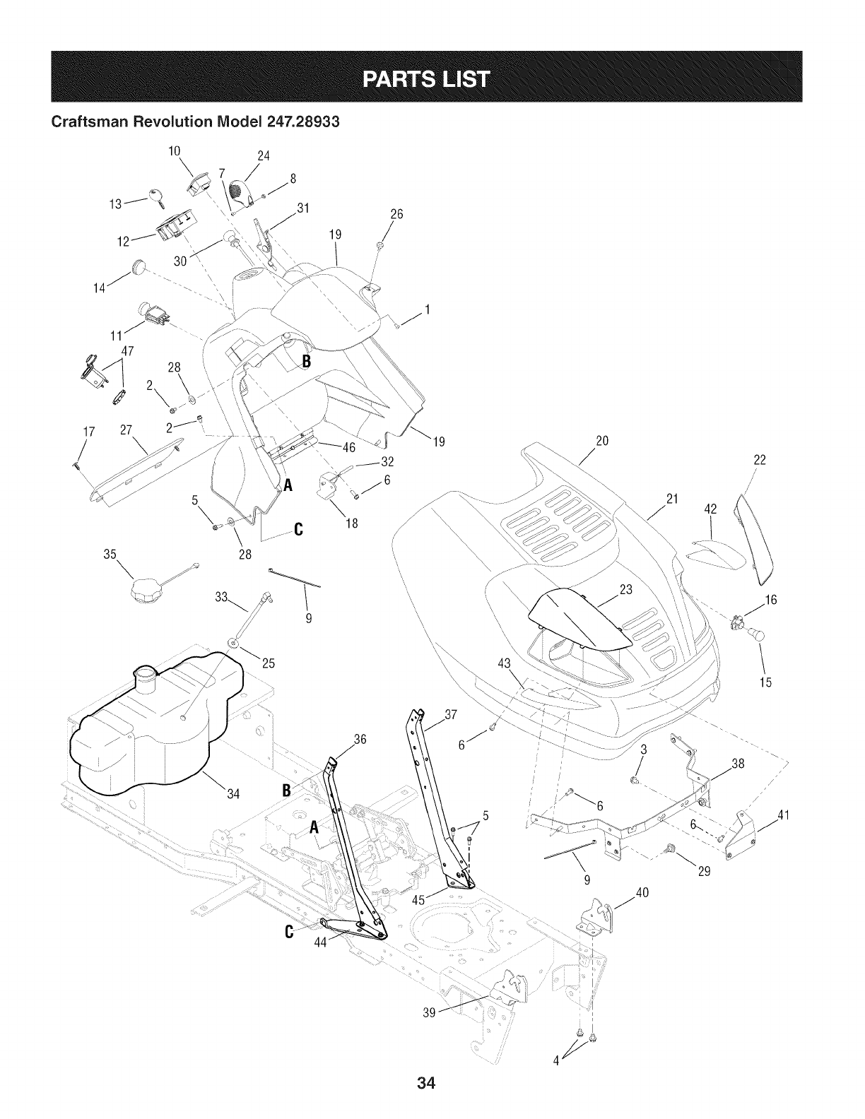
Craftsman Revolution IViodel 247.28933
17
/
10 24
\
\
35 28
9
19
\
18
\\
\\\,\\
2O
21 42
22
/
/
15
C
36
5
929
/
/41
34

Craftsman Revolution IViodel 247.28933
710-0192 Screw,TrussHd.Mach.,10-24x .375
2. 710-0599 Screw,HexWash,1/4-20x .5
3. 710-0604A Screw,HexWash,5/16-18x .625
4. 710-04484 Screw,HexWash,5/16-18x .75
5. 710-0642 Screw,HexWash,1/4-20x .75
6. 710-0895 Screw,HexWash,1/4-15x .75
7. 710-3217 Screw,TrussHd.Mach.,#8-32x .375
8. 712-0142 Nut,Hex,8-32
9. 725-0157 Tie, Cable
10. 925-04022B Meter,Indicator/ServiceMonitor
11. 925-04174 Switch,PTO
L
12. 925-04227B Switch,Ingition/Moduie
13. 925-1745A Key,Ignition,w/Plastic Cover
925-1744A Key,Ignition,w/o PlasticCover
14. 720-3025 Plug
15. 925-0963 Bulb,12VLight
16. 925-1649 Receptacle,Light
17. 726-3046 Clip,Ratchet
18. 731-04213 Lever,DashBrake
19. 731-05406 Panel,Dash
20. 731-06830 Hood
21. 731-05935 Plenum,Hood
22. 731-05525 Lens,HeadLightLH
23. 731-05526 Lens,HeadLightRH
24. 731-1857 Knob,ThrottleControl
25. 935-0149 Bushing,FuelTank
D = O e
735-0271A Bumper
27. 735-04076 Net,Storage
28. 936-0463 Washer,Flat,.25 x.63x.0515
29. 738-04091A Screw,Shoulder,.43x.29:TT5/16-18
30. 746-04132 Cable,ChokeControl
31. 746-1100 Cable,ThrottleControl
32. 747-1155 Rod,BrakeLockPivot
33. 751-10442 Fitting,FuelPickUp
34. 751-10692 Tank,Fuel
35. 751-10703 Cap,FuelTank
36. 783-04285F-0637 Support,Dash,R.H.
37. 783-04323F-0637 Support,Dash,L.H.
38. 683-04536 Bracket,HoodPivot
39. 783-04840-0637 Bracket,HoodPivotRH
40. 783-04841-0637 Bracket,HoodPivotLH
41. 783-05162-0637 Bracket,HoodSupport
42. 777X42426 Label,Reflector
43. 777X42427 Label,Reflector
44. 783-05140-0637 Brkt.,Strg.Support,RH
45. 783-04798-0637 Brkt.,Strg.Support,LH
46. 783-04799-0637 Brkt.,Support,UpperStrg.
47. 725-2003 12VPowerReceptacle
-- 925-04375A Harness,MainWire(IncludesFuse)
-- 925-1381 Fuse,20Amp
-- 937-04050 GreaseGunKit
35
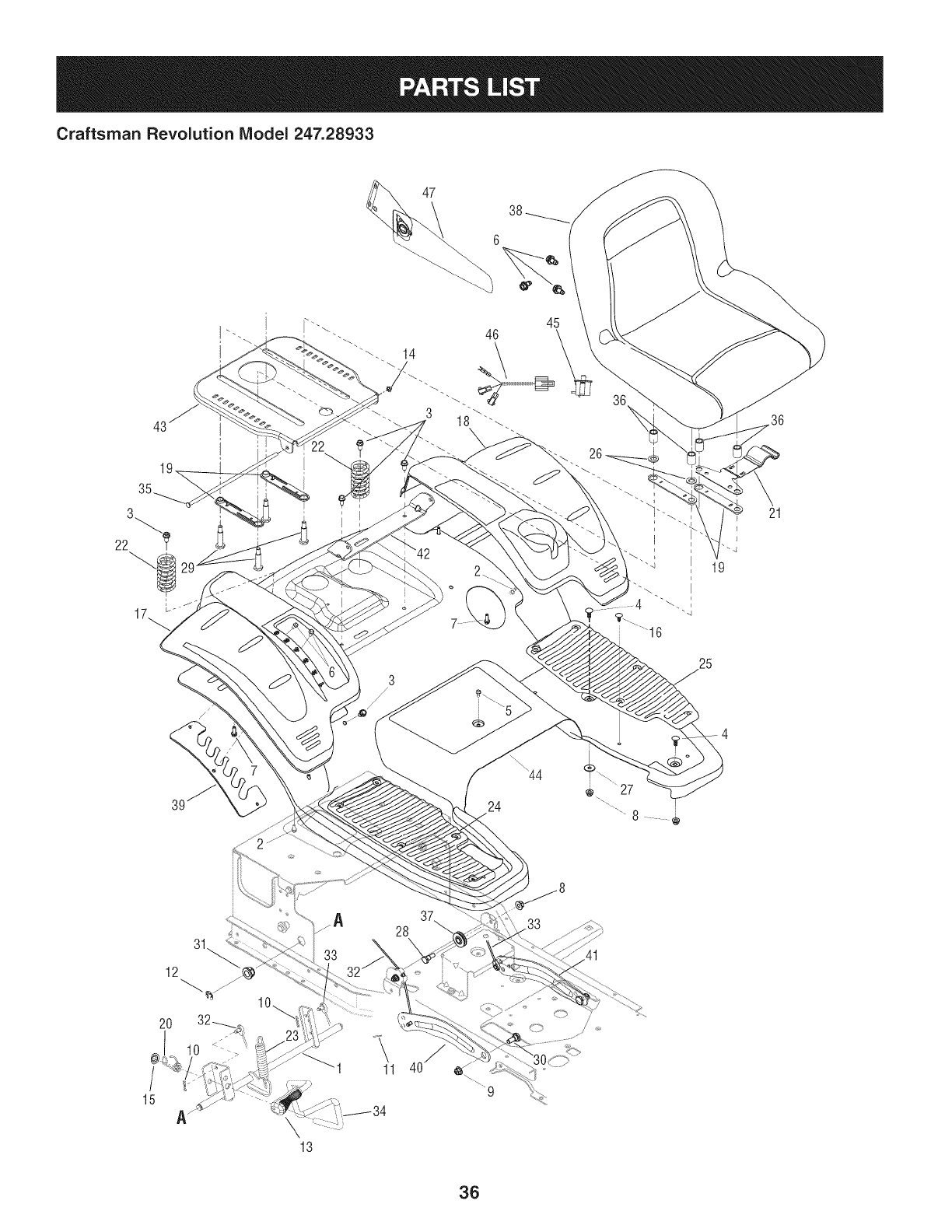
Craftsman Revolution IViodel 247.28933
45
/
24
19
25
21
15
12
11
28
36
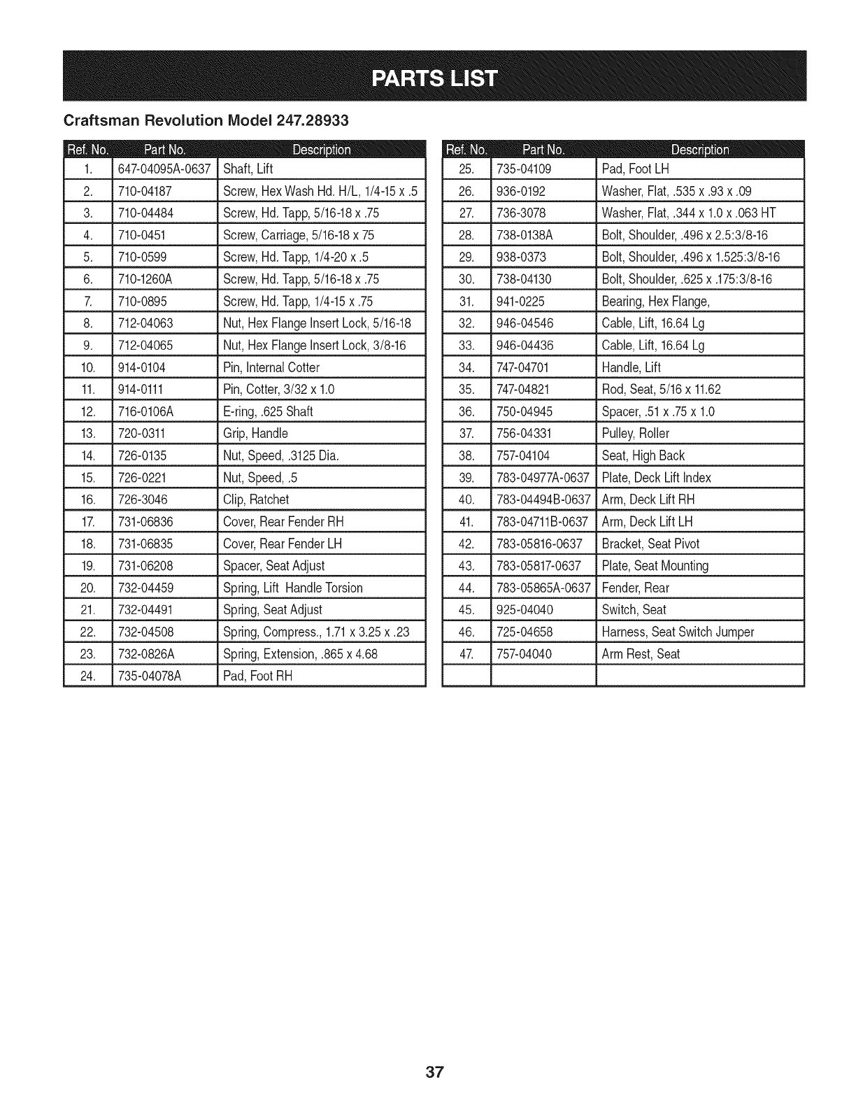
Craftsman Revolution IViodel 247.28933
|= o o
647-04095A-0637 Shaft, Lift
2. 710-04187 Screw,HexWashHd.H/L, 1/4-15x .5
3. 710-04484 Screw,Hd.Tapp,5/16-18x .75
4. 710-0451 Screw,Carriage,5/16-18x 75
5. 710-0599 Screw,Hd.Tapp,1/4-20x .5
6. 710-1260A Screw,Hd.Tapp,5/16-18x .75
7. 710-0895 Screw,Hd.Tapp,1/4-15x .75
8. _712-04063 _ Nut,HexFlangeinsertLock,5/16-18
9. 712-04065 Nut,HexFlangeinsertLock,3/8-16
10. 914-0104 Pin,InternalCotter
11. 914-0111 Pin,Cotter,3/32 x 1.0
12. 716-0106A E-ring,.625Shaft
13. 720-0311 Grip, Handle
14. 726-0135 Nut,Speed,.3125Dia.
15. 726-0221 Nut,Speed,.5
16. 726-3046 Clip,Ratchet
17. 731-06836 Cover,RearFenderRH
18. 731-06835 Cover,RearFenderLH
19. 731-06208 Spacer,SeatAdjust
20. 732-04459 Spring,Lift HandleTorsion
21. 732-04491 Spring,SeatAdjust
22. 732-04508 Spring,Compress.,1.71x 3.25x .23
23. 732-0826A Spring,Extension,.865x 4.68
24. 735-04078A Pad,FootRH
735-04109
26. 936-0192
27. 736-3078
28. 738o0138A
29. 938-0373
30. 738-04130
31. 941-0225
D = O O
Pad,FootLH
Washer,Fiat, .535x.93x.09
Washer,Fiat, .344x 1.0x .063 HT
Bolt,Shoulder,.496x 2.5:3/8-16
Bolt,Shoulder,.496x 1.525:3/8-16
Bolt,Shoulder,.625x.175:3/8-16
Bearing,HexFlange,
32. J 946-04546 J Cable,Lift, 16.64Lg
33. 946-04436 Cable,Lift, 16.64Lg
34. 747-04701 Handle,Lift
35. 747-04821 Rod,Seat,5/16x 11.62
36. 750-04945 Spacer,.51x.75x 1.0
37. 756-04331 Pulley,Roller
38. 757-04104 Seat,HighBack
39. 783-04977A-0637 Plate,DeckLift index
40. 783-04494B-0637 Arm,DeckLift RH
41. 783-04711B-0637 Arm,DeckLift LH
42. 783-05816-0637 Bracket,Seat Pivot
43. 783-05817-0637 Plate,SeatMounting
44. 783-05865A-0637 Fender,Rear
45. 925-04040 Switch,Seat
46. 725-04658 Harness,Seat SwitchJumper
47. 757-04040 Arm Rest,Seat
37
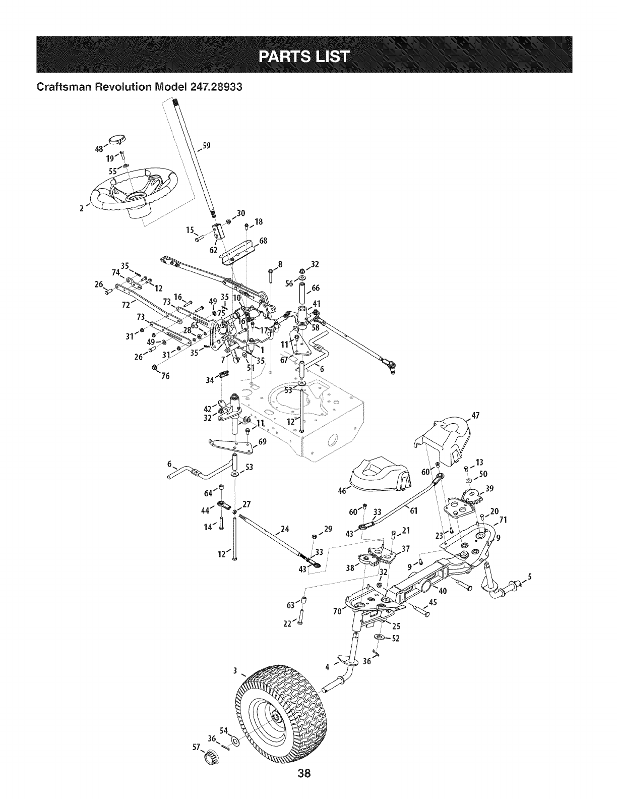
Craftsman Revolution IViodel247.28933
62
26
_..18
68
12"
/
63"_
22t_ 7
/?
47
38
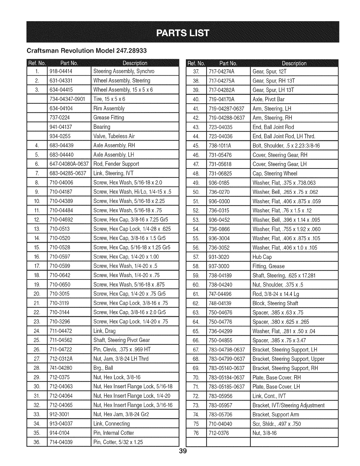
Craftsman Revolution Model 247.28933
|- 0 e
918-04414 SteeringAssembly,Synchro
2. 631-04331 WheelAssembly,Steering
3. 634-04415 WheelAssembly,15x 5 x 6
734-04347-0901 Tire, 15x 5 x 6
634-04104 RimAssembly
737-0224 GreaseFitting
941-04137 Bearing
934-0255 Valve,TubelessAir
4. 683-04439 Axle Assembly,RH
5. 683-04440 Axle Assembly,LH
6. J 647-04080A-0637 Rod,FenderSupport
7. 683-04285-0637 Link,Steering,IVT
8. 710-04006 Screw,HexWash,5/16-18x 2.0
9. 710-04187 Screw,HexWash,Hi/Lo, 1/4-15x .5
10. 710-04389 Screw,HexWash,5/16-18x 2.25
11. 710-04484 Screw,HexWash,5/16-18x .75
12. 710-04692 Screw,HexCap,3/8-16x 7.25Gr5
13. 710-0513 Screw,HexCapLock, 1/4-28x .625
14. _710-0520 _ Screw,HexCap,3/8-16x 1.5Gr5
15. 710-0528 Screw,HexCap,5/16-18x 1.25Gr5
16. 710-0597 Screw,HexCap,1/4-20x 1.00
17. 710-0599 Screw,HexWash,1/4-20x .5
18. 710-0642 Screw,HexWash,1/4-20x .75
19. 710-0650 Screw,HexWash,5/16-18x .875
20. 710-3015 Screw,HexCap,1/4-20x .75 Gr5
21. 710-3119 Screw,HexCapLock,3/8-16x .75
22. _710-3144 ,Screw,HexCap,3/8-16x 2.0 Gr5
23. 710-3296 Screw,HexCapLock, 1/4-20x .75
24. 711-04472 Link,Drag
25. ,711-04562 LShaft,SteeringPivotGear
26. 711-04722 Pin,Clevis,.375x.969HT
27. 712-0312A Nut,Jam,3/8-24 LHThrd
28. 741-04280 Brg.,Ball
29. 712-0375 Nut,HexLock,3/8-16
30. .712-04063 _ Nut,HexInsertFlangeLock,5/16-18
31. 712-04064 Nut,HexInsertFlangeLock,1/4-20
32. 712-04065 Nut,HexInsertFlangeLock,3/16-16
33. 912-3001 Nut,HexJam, 3/8-24Gr2
34. 913-04037 Link,Connecting
35. 914-0104 Pin,InternalCotter
36. 714-04039 Pin,Cotter,5/32 x 1.25
m = W O
717-04274A Gear,Spur, 12T
38. 717-04275A Gear,Spur,RH 13T
39. 717-04282A Gear,Spur,LH 13T
40. 719-04170A Axle,PivotBar
41. 719-04287-0637 Arm,Steering,LH
42. 719-04288-0637 Arm,Steering,RH
43. 723-04035 End,BallJointRod
44. 723-04036 End,BallJointRod,LHThrd.
45. 738-1011A Bolt,Shoulder,.5x 2.23:3/8-16
46. 731-05476 Cover,SteeringGear,RH
47. 731-05618 Cover,SteeringGear,LH
48. 731-06825 Cap,SteeringWheel
49. 936-0185 Washer,Fiat,.375x.738.063
50. 736-0270 Washer,Bell,.265x.75x.062
51. 936-0300 Washer,Fiat,.406x.875x.059
52. 736-0315 Washer,Fiat,.76x 1.5x .12
53. 936-0452 Washer,Bell,.396x 1.14x .095
54. 736-0866 Washer,Fiat,.755x 1.92x .060
55. 936-3004 Washer,Fiat,.406x.875x.105
56. 736-3052 Washer,Fiat,.406x 1.0x .105
57. 931-3020 HubCap
58. 937-3000 Fitting,Grease
59. 738-04189 Shaft,Steering,.625x 17.281
60. 738-04240 Nut,Shoulder,.375x.5
61. 747-04496 Rod,3/8-24x 14.4Lg
62. 748-04139 Block,SteeringShaft
63. 750-04676 Spacer,.385x.63 x.75
64. 750-04776 Spacer,.380x.625x.265
65. 736-04299 Washer,Fiat,.281x.50 x.04
66. 750-04855 Spacer,.385x.75x 3.47
67. 783-04798-0637 Bracket,SteeringSupport,LH
68. 783-04799-0637 Bracket,SteeringSupport,Upper
69. 783-05140-0637 Bracket,SteeringSupport,RH
70. 783-05184-0637 Plate,BaseCover,RH
71. 783-05185-0637 Plate,BaseCover,LH
72. 783-05956 Link,Cont.,IVT
73. 783-05957 Bracket,IVT/SteeringAdjustment
74. 783-05706 Bracket,SupportArm
75 710-04040 Scr,Shldr.,.497x.750
76 712-0376 Nut,3/8-16
39
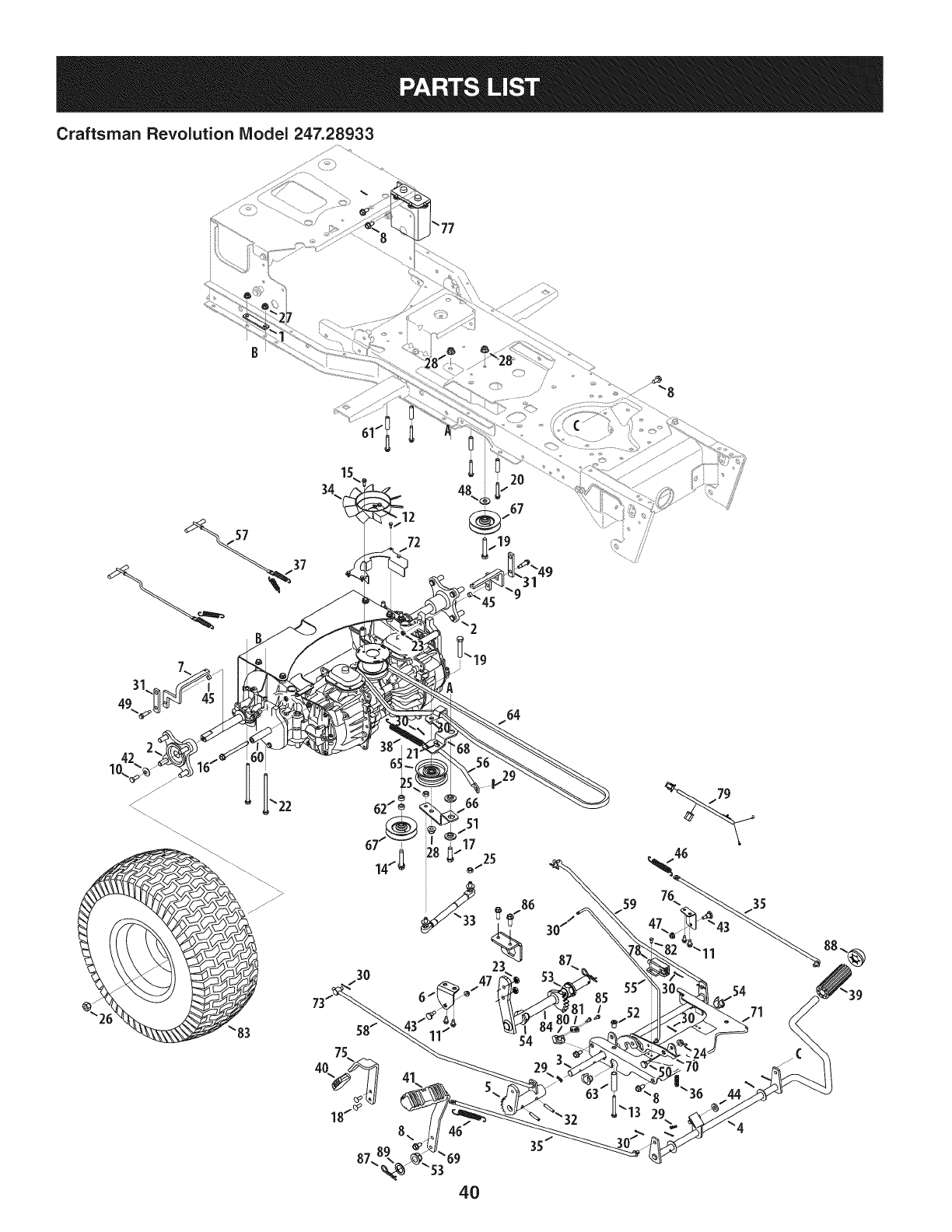
Craftsman Revolution IViodel 247.28933
3O
54
54
_53
4O
35
44
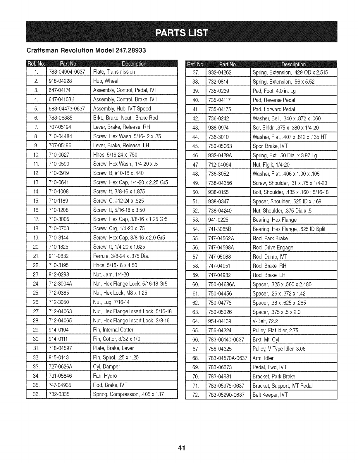
Craftsman Revolution IViodel 247.28933
783-04904-0637
2. 918-04228
3. 647-04174
4. 647-04103B
5. 683-04473-0637
6. 783-06385
707-05194
8. 710-04484
9. 707-05196
10. 710-0627
11. 710-0599
12. 710-0919
13. 710-0641
14. 710-1008
D = O O
Plate,Transmission
Hub,Wheel
Assembly,Control,Pedal,IVT
Assembly,Control,Brake,IVT
Assembly,Hub,IVTSpeed
Brkt.,Brake,Neut.,BrakeRod
Lever,Brake,Release,RH
Screw,HexWash,5/16-12x .75
Lever,Brake,Release,LH
Hhcs,5/16-24x .750
Screw,HexWash.,1/4-20x .5
Screw,B, #10-16x .440
Screw,HexCap,1/4-20x 2.25 Gr5
Screw,tt, 3/8-16x 1.875
710-1189 Screw,C,#12-24x.625
15.
16. 710-1208 Screw,tt, 5/16-18x 3.50
17. 710-3005 Screw,HexCap,3/8-16x 1.25Gr5
18. 710-0703 Screw,Crg,1/4-20x .75
19. 710-3144 Screw,HexCap,3/8-16x 2.0 Gr5
20. 710-1325 Screw,tt, 1/4-20x 1.625
21. 911-0832 Ferrule,3/8-24 x .375Dia.
22. 710-3195 Hhcs,5/16-18x 4.50
23. 912-0298
24. 712-3004A
25. 712-0365
26. 712-3050
2_ 712-04063
28. 712-04065
29. 914-0104
30. 914-0111
Nut,Jam, 1/4-20
Nut, HexFlangeLock,5/16-18Gr5
Nut, HexLock, M8x 1.25
Nut, Lug,7/16-14
Nut, HexFlangeInsertLock,5/16-18
Nut, HexFlangeInsertLock,3/8-16
Pin, InternalCotter
Pin,Cotter,3/32 x 1/0
31. 718-04597 Plate,Brake,Lever
32. 915-0143 Pin,Spirol,.25 x 1.25
33. 727-0626A Cyl, Damper
34. 731-05846 Fan,Hydro
35. 747-04935 Rod,Brake,IVT
36. 732-0335 Spring,Compression,.405x 1.17
m = _ 0
932-04262 Spring,Extension,.429OD x 2.515
38. 732-0814 Spring,Extension,.56 x 5.52
39. 735-0239 Pad,Foot,4.0 in. Lg
40. 735-04117 Pad,ReversePedal
41. 735-04175 Pad,ForwardPedal
42. 736-0242 Washer,Bell,.340x.872x.060
43. 938-0974 Scr,Shldr,.375x.380x 1/4-20
44. 736-3010 Washer,Flat,.407x.812x.135HT
45. 750-05063 Spcr,Brake,IVT
46. 932-0429A Spring,Ext, .50 Dia.x 3.97Lg.
47. 712-04064 Nut,FIglk,1/4-20
48. 736-3052 Washer,Flat,.406x 1.00x .105
49. 738-04356 Screw,Shoulder,.31x.75x 1/4-20
50. 938-0155 Bolt,Shoulder,.435x.160: 5/16-18
51. 938-0347 Spacer,Shoulder,.625IDx .169
52. 738-04240 Nut,Shoulder,.375Dia x .5
53. 941-0225 Bearing,HexFlange
54. 741-3065B Bearing,HexFlange,.625ID Split
55. 747-04562A Rod,ParkBrake
56. 747-04598A Rod,DriveEngage
57. 747-05088 Rod,Dump,IVT
58. 747-04951 Rod,Brake RH
59. 747-04932 Rod,Brake LH
60. 750-04686A Spacer,.325x.500x 2.480
61. 750-04456 Spacer,.26x.372x 1.42
62. 750-04776 Spacer,.38x.625x.265
63. 750-05026 Spacer,.375x.5 x 2.0
64. 954-04139 V-Belt,72.2
65. 756-04224 Pulley,FlatIdler,2.75
66. 783-06140-0637 Brkt,Mt, Cyl
67. 756-04325 Pulley,V TypeIdler,3.06
68. 783-04570A-0637 Arm,Idler
69. 783-06373 Pedal,Fwd,IVT
70. 783-04981 Bracket,ParkBrake
71. 783-05976-0637 Bracket,Support,IVTPedal
72. 783-05290-0637 BeltKeeper,IVT
41
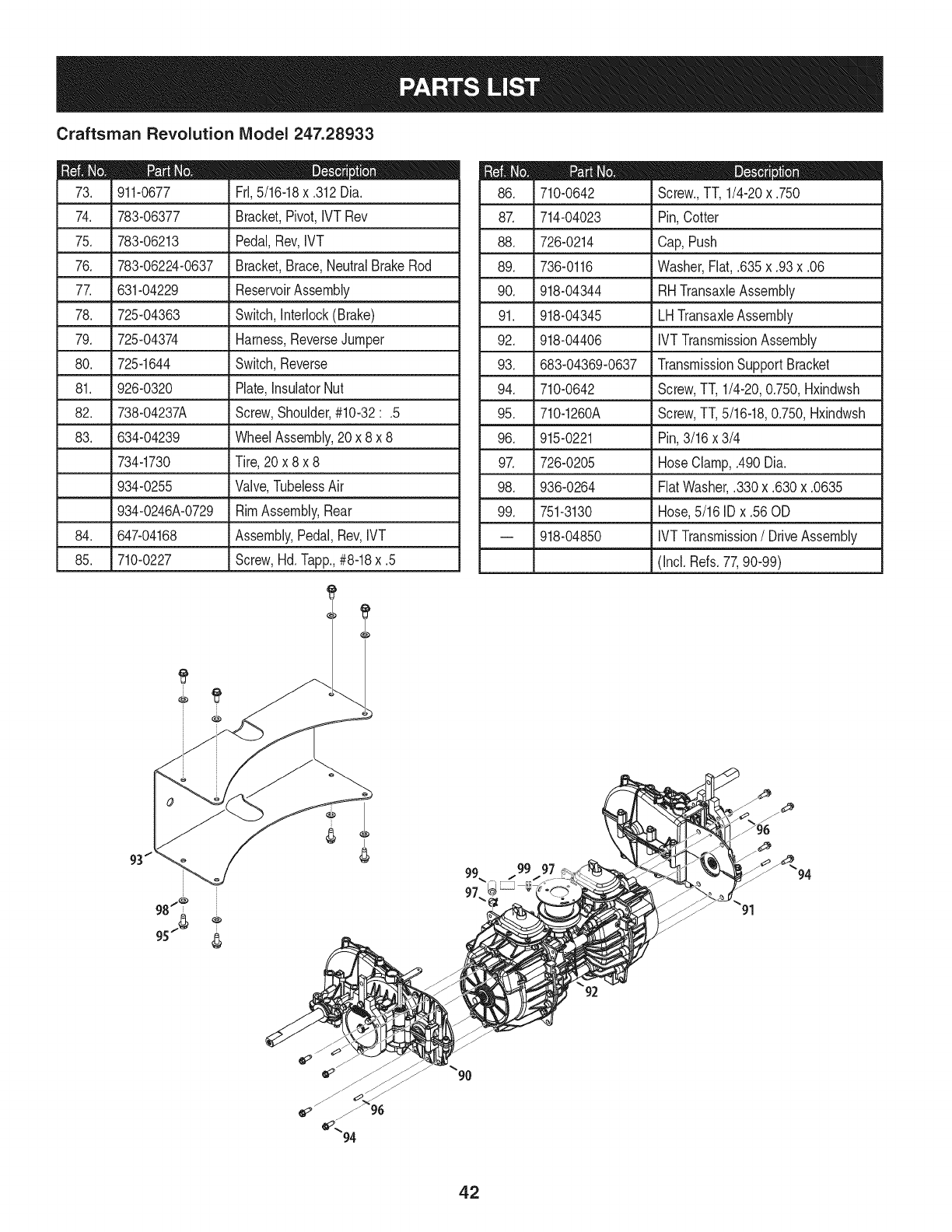
Craftsman Revolution IViodel 247.28933
D = O
911-0677 FrI,5/16-18x .312Dia.
74. 783-06377 Bracket,Pivot,IVT Rev
75. 783-06213 Pedal,Rev,IVT
76. 783-06224-0637 Bracket,Brace,NeutralBrakeRod
77. 631-04229 ReservoirAssembly
78. 725-04363 Switch,Interlock(Brake)
79. 725-04374 Harness,ReverseJumper
80. 725-1644 Switch,Reverse
81. 926-0320 Plate,InsulatorNut
82. 738-04237A Screw,Shoulder,#10-32:.5
83. 634-04239 WheelAssembly,20 x 8 x 8
734-1730 Tire,20 x 8 x 8
934-0255 Valve,TubelessAir
934-0246A-0729 RimAssembly,Rear
84. 647-04168 Assembly,Pedal,Rev,IVT
85. 710-0227 Screw,Hd.lapp., #8-18x .5
m = O
710-0642 Screw.,TT, 1/4-20x .750
87. 714-04023 Pin,Cotter
88. 726-0214 Cap,Push
89. 736-0116 Washer,Fiat,.635x.93x.06
90. 918-04344 RHTransaxleAssembly
91. 918-04345
92. 918-04406
93. 683-04369-0637
94. 710-0642
95. 710-1260A
LHTransaxleAssembly
IVTTransmissionAssembly
TransmissionSupportBracket
Screw,TT, 1/4-20,0.750,Hxindwsh
Screw,TT,5/16-18,0.750,Hxindwsh
96. 915-0221
9_ 726-0205
98. 936-0264
99. 751-3130
-- 918-04850
Pin,3/16 x 3/4
HoseClamp,.490Dia.
FiatWasher,.330x.630x.0635
Hose,5/16 IDx .56 OD
IVTTransmission/DriveAssembly
(Incl. Refs.77,90-99)
96
42
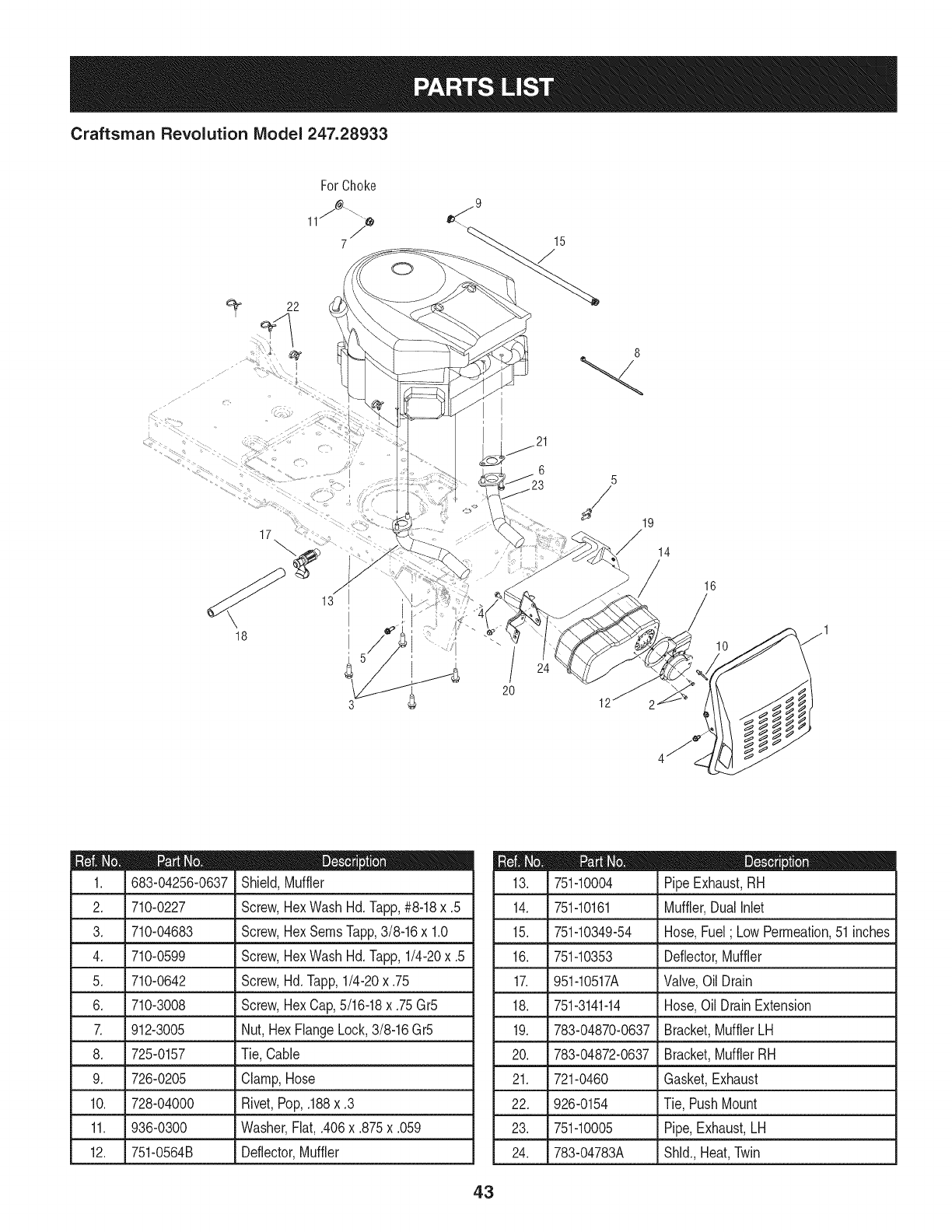
Craftsman Revolution Model 247.28933
22
0
15
I
17 :
18
5//
20
8
14
16
m = O O
683-04256-0637 Shield,Muffler
2. 710-0227 Screw,HexWashHd.Tapp,#8-18x .5
3. 710-04683 Screw,HexSeresTapp,3/8-16x 1.0
4. 710-0599 Screw,HexWashHd.lapp, 1/4-20x .5
5. 710-0642 Screw,Hd.lapp, 1/4-20x .75
6. 710-3008 Screw,HexCap,5/16-18x .75Gr5
7. 912-3005 Nut, HexFlangeLock,3/8-16Gr5
8. 725-0157 Tie,Cable
9. 726-0205 Clamp,Hose
10. 728-04000 Rivet,Pop,.188x.3
11. J936-0300 . Washer,Fiat, .406x.875 x.059
12. 751-0564B Deflector,Muffler
D = O
751-10004 PipeExhaust,RH
14. 751-10161 Muffler,DualNet
15. 751-10349-54 Hose,Fuel; LowPermeation,51inches
16. 751-10353 Deflector,Muffler
17. 951-10517A Valve,OilDrain
18. 751-3141-14 Hose,Oil DrainExtension
19. 783-04870-0637 Bracket,MufflerLH
20. 783-04872-0637 Bracket,MufflerRH
21. 721-0460 Gasket,Exhaust
22. 926-0154 Tie, PushMount
23. 751-10005 Pipe,Exhaust,LH
24. 783-04783A Shld.,Heat,Twin
43
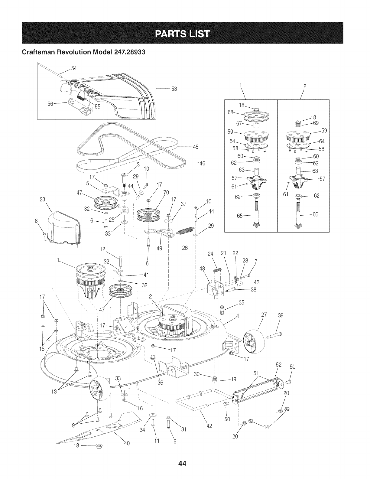
Craftsman Revolution Model 247.28933
23\
8\
17
®
21 22
1 2
\/
18_
60 _D
62/_
<_.y_----60
_--62
_63
7_ 57
61 _62
66
27 39
15
31
6
5O
42
51
20
52 5O
/
20
44
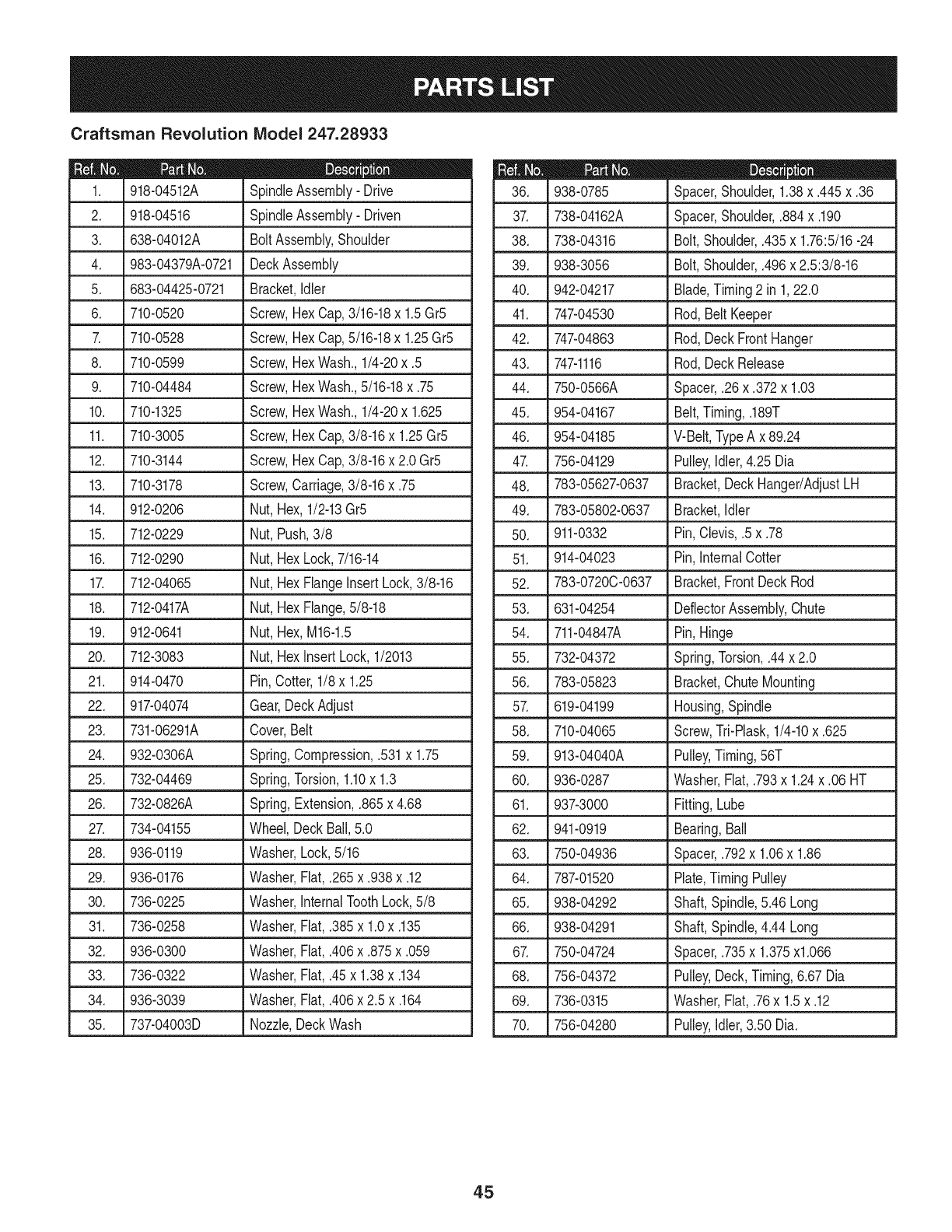
Craftsman Revolution IViodel 247.28933
D = _
918-04512A SpindleAssembly- Drive
2. 918-04516 SpindleAssembly- Driven
3. 638-04012A BoltAssembly,Shoulder
4. 983-04379A-0721 DeckAssembly
5. 683-04425-0721 Bracket,Idler
6. 710-0520 Screw,HexCap,3/16-18x 1.5Gr5
7. 710-0528 Screw,HexCap,5/16-18x 1.25Gr5
8. 710-0599 Screw,HexWash.,1/4-20x .5
9. 710-04484 Screw,HexWash.,5/16-18x .75
10. 710-1325 Screw,HexWash.,1/4-20x 1.625
11. 710-3005 Screw,HexCap,3/8-16x 1.25Gr5
12. 710-3144 Screw,HexCap,3/8-16x 2.0Gr5
13. 710-3178 Screw,Carriage,3/8-16x .75
14. 912-0206 Nut,Hex,1/2-13Gr5
15. 712-0229 Nut,Push,3/8
16. 712-0290 Nut,HexLock,7/16-14
17. 712-04065 Nut,HexFlangeInsert Lock,3/8-16
18. 712-0417A Nut,HexFlange,5/8-18
19. 912-0641 Nut,Hex,M16-1.5
20. 712-3083 Nut,HexInsertLock,1/2013
21. 914-0470 Pin,Cotter,1/8x 1.25
22. 917-04074 Gear,DeckAdjust
23. 731-06291A Cover,Belt
24. 932-0306A Spring,Compression,.531x 1.75
25. 732-04469 Spring,Torsion,1.10x 1.3
26. 732-0826A Spring,Extension,.865x 4.68
27. 734-04155 Wheel,Deck Ball,5.0
28. 936-0119 Washer,Lock,5/16
29. 936-0176 Washer,Fiat,.265x.938x.12
30. 736-0225 Washer,InternalToothLock,5/8
31. 736-0258 Washer,Fiat,.385x 1.0x .135
32. 936-0300 Washer,Fiat,.406x.875x.059
33. 736-0322 Washer,Fiat,.45x 1.38x .134
34. 936-3039 Washer,Fiat,.406x 2.5 x .164
35. 737-04003D Nozzle,DeckWash
m = O
938-0785 Spacer,Shoulder,1.38x .445x.36
37. 738-04162A Spacer,Shoulder,.884x.190
38. 738-04316 Bolt,Shoulder,.435x 1.76:5/16-24
39. 938-3056 Bolt,Shoulder,.496x 2.5:3/8-16
40. 942-04217 Blade,Timing2 in 1,22.0
41. 747-04530 Rod,BeltKeeper
42. 747-04863 Rod,DeckFrontHanger
43. 747-1116 Rod,DeckRelease
44. 750-0566A Spacer,.26 x.372x 1.03
45. 954-04167 Belt,Timing,.189T
46. 954-04185 V-Belt,TypeA x 89.24
47. 756-04129 Pulley,Idler,4.25 Dia
48. 783-05627-0637 Bracket,DeckHanger/AdjustLH
49. 783-05802-0637 Bracket,Idler
50. 911-0332 Pin,Clevis,.5 x.78
51. 914-04023 Pin,InternalCotter
52. 783-0720C-0637 Bracket,FrontDeckRod
53. 631-04254 DeflectorAssembly,Chute
54. 711-04847A Pin,Hinge
55. 732-04372 Spring,Torsion,.44x 2.0
56. 783-05823 Bracket,ChuteMounting
57. 619-04199 Housing,Spindle
Screw,Tri-Plask,1/4-10x .625
Pulley,Timing,56T
Washer,Fiat, .793x 1.24x .06 HT
Fitting,Lube
Bearing,Ball
Spacer,.792x 1.06x 1.86
Plate,TimingPulley
Shaft,Spindle,5.46Long
Shaft,Spindle,4.44Long
Spacer,.735x 1.375xl.066
Pulley,Deck,Timing,6.67Dia
Washer,Fiat, .76x 1.5x .12
Pulley,Idler,3.50 Dia.
58. 710-04065
59. 913-04040A
60. 936-0287
61. 937-3000
62. 941-0919
63. 750-04936
64. 787-01520
65. 938-04292
66. 938-04291
67. 750-04724
68. 756-04372
69. 736-0315
70. 756-04280
45
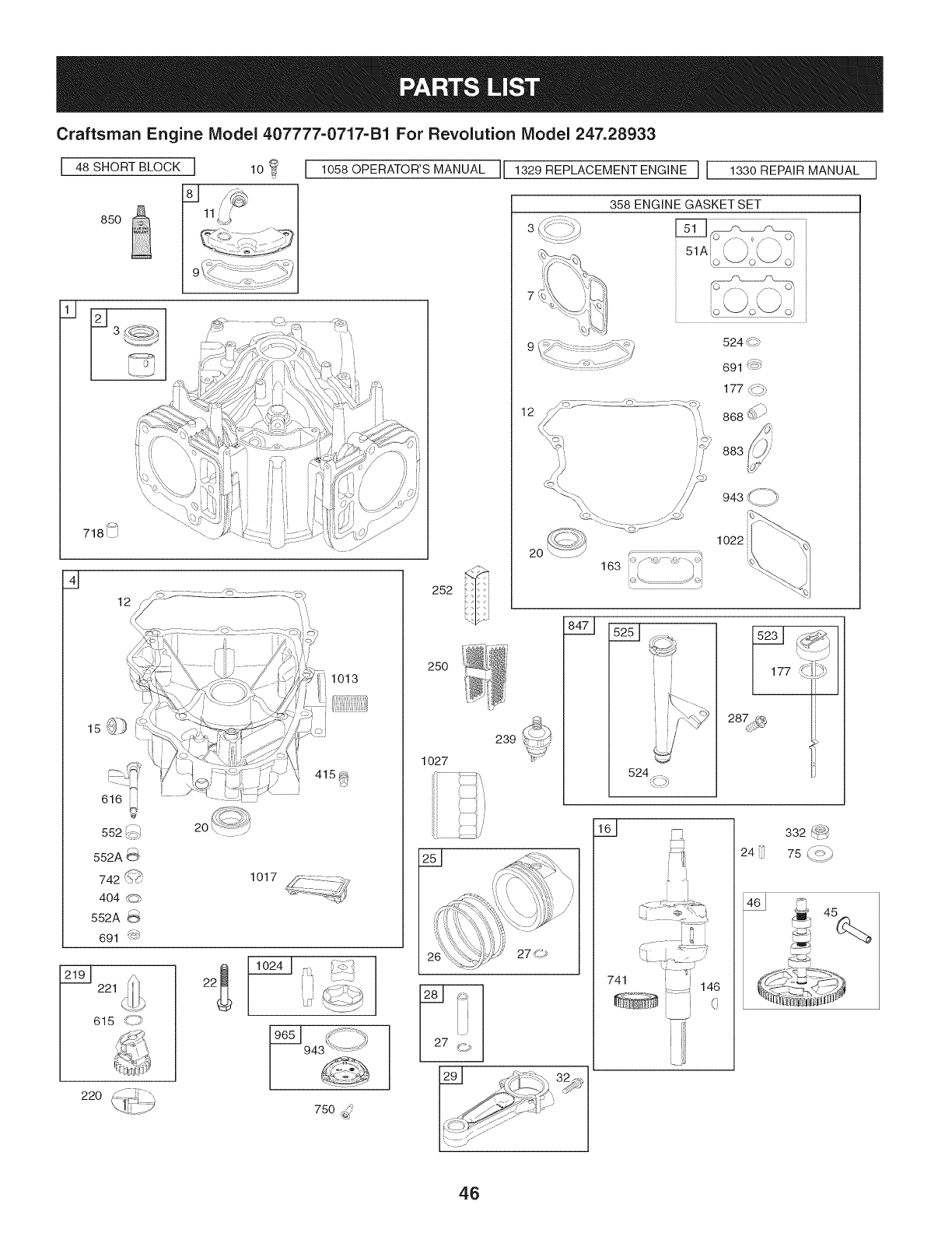
Craftsman Engine Model 407777=0717=B1 For Revolution Model 247.28933
I 48 SHORT BLOCK I
q
850 11L4
_ ...... i ¸
| ......
1058 OPERATOR'S MANUAL
616 i,
552 _,
552A
742 S(_
404
r--,
552A
691 s_
221
615 _=_
1013
i
i
1017 _Z_-_...... _._
7-
t_
7i
252
25O
1O27
2
220 (_))
1 ]
I[ 1329 REPLACEMENT ENGINE ] 1330 REPAIR MANUAL
iL
2O C= 7:2_::::o ."3s
163 i'_/_ ..... \_"_i
943 \: j
1022
239
251 _
524 ,((::p)
F:::_[
"i •_•i"_
741 l i
::: ::::: 146
i (
24
332 f_@
/_-_
75 y=i
D- 45
750 :,_ I_ _/Z_ I
46
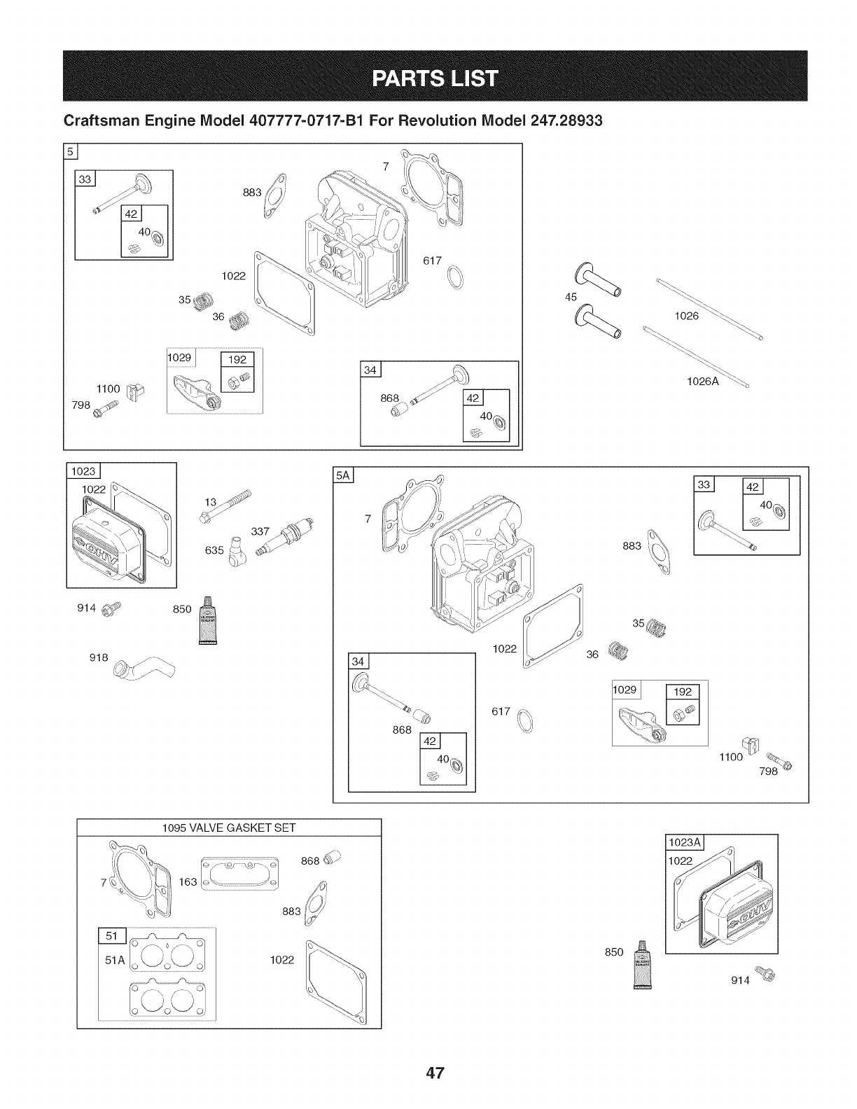
Craftsman Engine IViodel 407777-0717-B1 For Revolution IViodel 247.28933
883
1022
617
1026 _
"_
1026A ""_.'%
914 _ 850
918
635
337
868
1022
617
36
883
®
1022 85O
914 _@
47
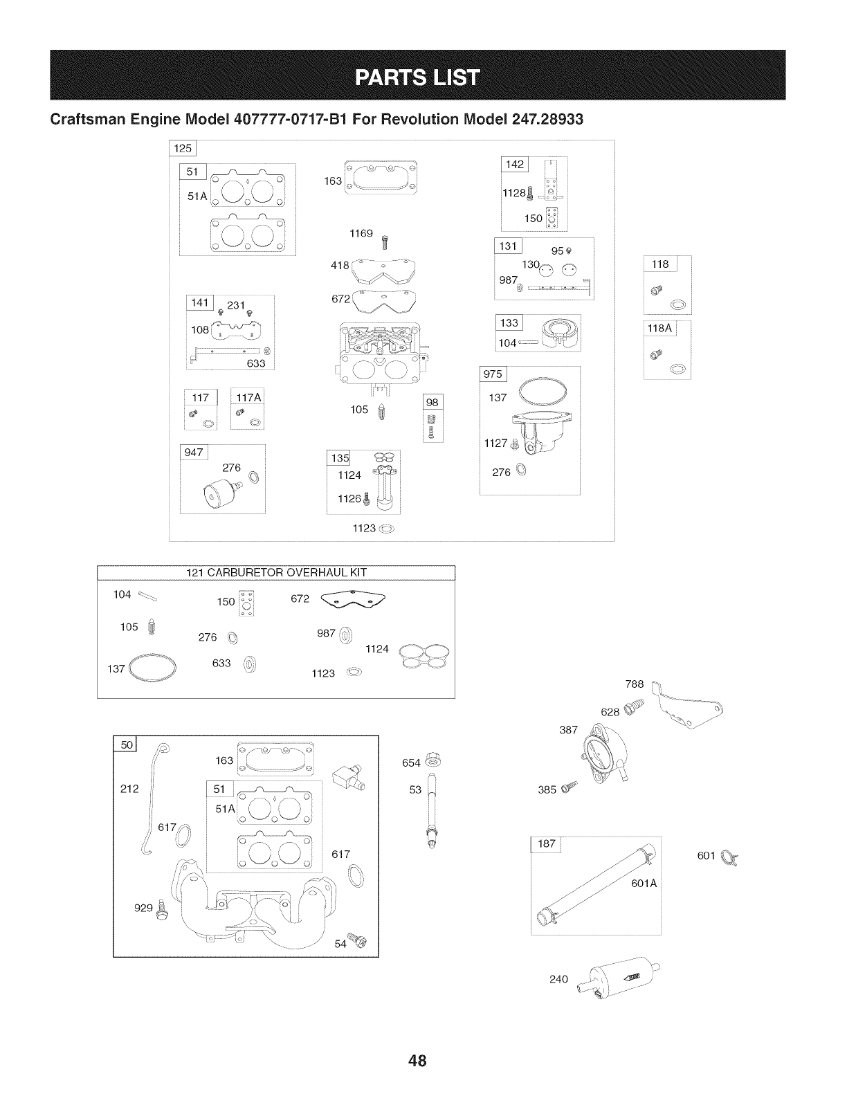
Craftsman Engine Model407777-0717=B1For Revolution Model 247.28933
108 _- _J_'_<"
\_ / \? i
633
163,£ /_._}
y
1169
418 <_ _ .... ,_...
672 \ _' )
_1128_ '_:
15o_,S
987@
©i ©
276
lOS
1124
1126_
1123 _._
118A
J
137
212
929_
121 CARBURETOR OVERHAUL KIT
150 _ 672
o£j
276 _ 987 _h
\,5_' 1124
633 1123 _-_
_)/.o/ '.,% -\ _4
163
\_ J
°'" o\Jot, jd
617
s-%
654 <_-*_
53 ::bl
387
385 ¢_
601 _,%<
24O
48
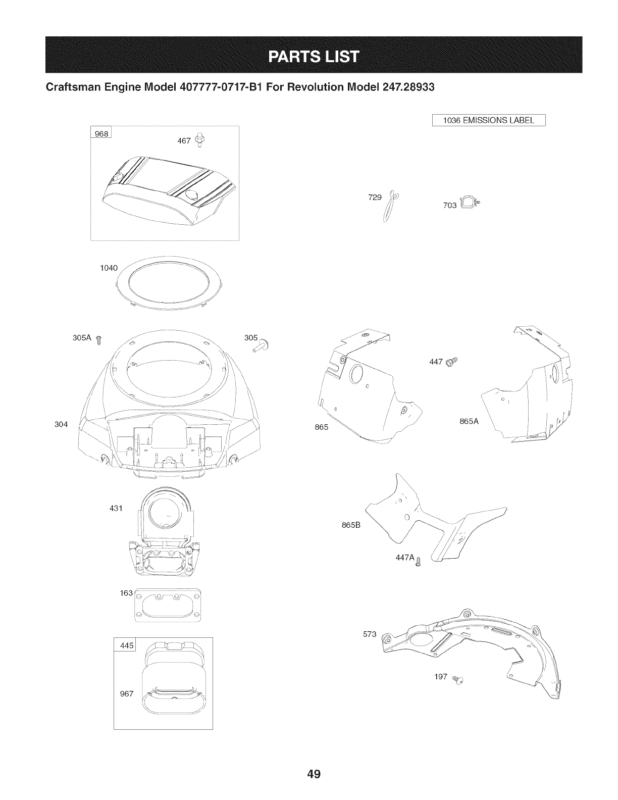
Craftsman Engine IViodel 407777=0717-B1 For Revolution IViodel 247.28933
467 _.>'
U
1036 EMISSIONS LABEL
729 _,d 4_
703 k_.:::,J___
304
305A
_- .............. -. -.
431 i
I865B 0
447A_
447 (_
/
/
/
/
865A ',,
967
573
49
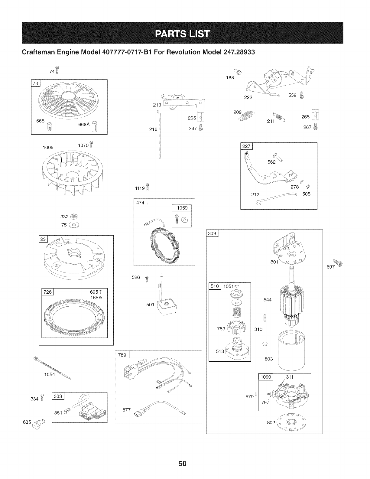
Craftsman Engine IViodel 407777-0717-B1 For Revolution IViodel 247.28933
@
74
188
668
1005
332 _<-_P_
)
213 _.#,j
265 J
216 267
H
1119U
474
526
5Ol_ _.._
789
877 >_' "_._
222 559 ]oJ
@
265 ii_i
267_
562 _
278
212 ......::s- : : :q
::::::::::::::::::::
5O5
801
_1051<"
783
513
544
310
803
311
579 !_
5O

Craftsman Engine IViodel 407777=0717=B1 For Revolution IViodel 247.28933
795118 CylinderAssembly
2 499585 Kit-Bushing/Seal(MagnetoSide)
3. 391086s Seal-Oil(MagnetoSide)
4 796230 Sump-Engine
5 796231 Head-Cylinder(Cylinder#1)
5A 796232 Head-Cylinder(Cylinder#2)
7.+ 693997 Gasket-CylinderHead
8 792185 BreatherAssembly
9 690937 Gasket-Breather
10 697551 Screw(BreatherAssembly)
11 792184 Tube-Breather
12. 697227 Gasket-Crankcase
13 793988 Screw(CylinderHead)
15 690946 Plug-OilDrain
16 796540 Crankshaft
20, 795387 Seal-Oil(PTOSide)
22 694966 Screw(CrankcaseCover/Sump)
23 691053 Flywheel
24 222698s Key-Flywheel
25 793647 PistonAssembly(Standard)
793648 PistonAssembly(.020"Oversize)
26 791787 RingSet(Standard)
791792 RingSet(.020"Oversize)
27 690975 Lock-PistonPin
28 696581 Pin-Piston
29 796209 Rod-Connecting
32 690976 Screw(ConnectingRod)
33 697576 Valve-Exhaust
34 792200 Valve-Intake
35 694865 Spring-Valve(Intake)
36 694865 Spring-Valve(Exhaust)
40 690964 Retainer-Valve
42 499586 Keeper-Valve
45 690977 Tappet-Valve
46 792555 Camshaft
48 698172 Short Block
50 695241 Manifold-Intake
510.+ 795123 Gasket-intake
D = O 0
690950 Gasket-intake
53 690951 Stud(Carburetor)
54 699816 Screw(IntakeManifold)
73 494439 Screen-Rotating
74 698425 Screw(RotatingScreen)
75 691056 Washer(Flywheel)
95 690718 Screw(ThrottleValve)
98 0 699721 Kit-IdleSpeed
1040 694918 Pin-FloatHinge
1050 698537 Valve-FloatNeedle
108 699723 Valve-Choke
117 792296 Jet-Main(Standard)(LeftJet)
117A 842627 Jet-Main(Standard)(RightJet)
118 699457 Jet-Main(HighAltitude)(LeftJet)
118A 699733 Jet-Main(HighAltitude)(RightJet)
121 792455 Kit-CarburetorOverhaul
125 792295 Carburetor
130 690993 Valve-Throttle
131 499805 Kit-ThrottleShaft
133 699724 Float-Carburetor
135 699729 Tube-FuelTransfer
1370 690994 Gasket-FloatBowl
141 699722 Kit-ChokeShaft
142 699726 Nozzle-Carburetor
146 690979 Key-Timing
150 690995 Gasket-Nozzle
163 691001 Gasket-AirCleaner
165 693148 Nut(RingGear)
187 791766 Line-Fuel(CutTo RequiredLength)
188 697551 Screw(ControlBracket)
192 690083 Adjuster-RockerArm
197 697820 Screw(BackPlate)
209 796224 Spring-Governor(Yellow/Black)
211 691019 Spring-GovernedIdle(Orange)
212 695238 Link-Throttle
213 691021 Bracket-ChokeControl
216 691022 Link-Choke
219 793338 Gear-Governor
• IncludedinEngineGasketSet, KeyNumber358.
0 Includedin CarburetorOverhaulKit,KeyNumber121.
+ IncludedinValveGasketSet,KeyNumber1095.
51

Craftsman Engine IViodel 407777=0717=B1 For Revolution IViodel 247.28933
690412 Washer(GovernorGear)
221 841026 Cup-Governor
222 796630 Bracket-Control
227 796223 Lever-GovernorControl
231 690718 Screw(ChokeValve)
239 792028 Switch-OilPressure
240 695666 Filter-Fuel
250 690957 Retainer-Breather
252 794389 Collector-Oil
265 691024 Clamp-Casing
267 695314 Screw(CasingClamp)
276 695410 Washer-Sealing
278 792651 Washer(GovernorControlLever)
287 697551 Screw(DipstickTube)
304 796678 Housing-Blower
305 691005 Screw(BlowerHousing)
305A 790690 Screw(BlowerHousingto IntakeElbow)
306 794953 Shield-Cylinder
309 497595 Motor-Starter
310 690323 Screw(StarterMotor)
311 497608 BrushSet
332 691059 Nut(Flywheel)
333 691060 Armature-Magneto
334 691061 Screw(MagnetoArmature)
337 491055s Plug-Spark
358 694012 GasketSet-Engine
385 697551 Screw(Fuel Pump)
387 808656 Pump-Fuel
404 690442 Washer(GovernorCrank)
415 690283 Plug(CrankcaseCover/Sump)
418 690999 Plate-Carburetor
431 792297 Elbow-Intake
445 792105 Filter-AirCleanerCartridge
447 691003 Screw(Air GuideCover)(Short)
447A 697551 Screw(Air GuideCover)(Long)
467 790697 Knob-AirCleaner
474 696457 Alternator
_= " O O
691188 Regulator
505 691029 Nut(GovernorControlLever)
510 696541 Drive-Starter
513 692024 Clutch-Drive
523 1691036 J D!pst!ck
524 691032
525 691037
526 691129
544 692034
552 690552
552A 690553
559 695314
562 690311
573
579
601
Seal-DipstickTube
Tube-Dipstick
•Screw(Regulator)
Armature-Starter
Bushing-GovernorCrank
Bushing-GovernorCrank
Screw(RemoteChoke)
Bolt (GovernorControlLever)
790444 Plate-Back
691029 Nut(StarterCable)
691038 Hose-Clamp(Black)
601A 791850 Hose-Clamp(Green)
615 698290 Retainer-GovernorShaft
616 691045 Crank-Governor
617 697891 SeaI-ORing(intakeManifold)(Red)
628 697551 Screw(FuelPumpBracket)
633 690998 Seal-Choke/ThrottleShaft
635 66538s Boot-SparkPlug
654 690958 Nut(Carburetor)
668 691500 Spacer(RotatingScreen)
668A 691215 Spacer(RotatingScreen)
672 690234 Gasket-CarburetorPlate
691 790574 Seal-GovernorShaft
695 693149 Screw(RingGear)
697 690372 Screw(DriveCap)
703 691010 Clip
718 690959 Pin-Locating(Cylinder)
726 499612 Gear-Ring
729 694123 Clip-Wire
741 690980 Gear-Timing
742 690328 Retainer-ERing
750 796208 Screw(Oil PumpCover)
• includedin EngineGasketSet,KeyNumber358.
O IncludedinCarburetorOverhaulKit,KeyNumber121.
+ IncludedinValveGasketSet,KeyNumber1095.
52

Craftsman Engine IViodel 407777=0717=B1 For Revolution IViodel 247.28933
D = O
695708 Gear-Pinion
788 793145 Bracket-FuelPump
789 698330 Harness-Wiring
797 693167 Nut(BrushRetainer)
798 697890 Screw(RockerArm)
801 691283 Cap-Drive
802 691286 Cap-End
803 Housing-Starter(Servicedby497595
StarterMotorOnly,Reference309)
842 691031 Seal-ORing(DipstickTube)
847 499602 Dipstick/TubeAssembly
850 100106 Sealant-Liquid(LiquidSealantis inter
changeablewiththe RockerCover
Gasketand BreatherGasket)
851 493880s Terminal-SparkPlug
865 691012 Cover-AirGuide(Cylinder#1)
865A 796541 Cover-AirGuide(Cylinder#2)
865B 792286 Cover-AirGuide(Valley)
868o+ 690968 Seal-Valve
877 790544 Wire/Connector-Alternator
883° 690970 Gasket-Exhaust
914 691127 Screw(RockerCover)
918 793147 Hose-Vacuum
929 695239 Screw(ChokeControlBracket)
943 796222 Seal-ORing(Oil PumpCover)
947 841546 Solenoid-Fuel
965 796221 Cover-OilPump
967 792303 Filter-PreCleaner
968 795120 Cover-AirCleaner
975 793592 Bowl-Float
987 691000 Seal-ThrottleShaft
_= O O
791236 Fan-Flywheel
1013 690954 Nipple-OilFilter
1017 796214 Screen-OilPump
1022.+ 690971 Gasket-RockerCover
1023 793146 Cover-Rocker(Cylinder#1)
1023A 499600 Cover-Rocker(Cylinder#2)
1024 796220 Pump-Oil
1026 690981 Rod-Push(Steel)
690982 Rod-Push(Aluminum)
1027 795890 Filter-Oil
1029 690972 Arm-Rocker
1036 Label-Emissions(Availablefroma Briggs
& StrattonAuthorizedDealer)
1040 791237 Plate-Trim
1051 691265 Ring-Retaining(StarterMotor)
1054 280275 Tie-Cable
1058 277103 Operator'sManual
1059 698516 Kit-Screw/Washer(Alternator)
1070 791680 Screw(FlywheelFan)
1090 691293 Retainer-Brush
1095 694013 GasketSet-Valve
1100 791959 Pivot-RockerArm
1119 691183 Screw(Alternator)
1123 841653 Seal-ORing(SolenoidRetainer)
1124 690988 Seal-ORing(FuelTransferTube)
1126 690991 Screw(FuelTransferTube)
1127 695407 Screw(FloatBowl)
1128 690990 Screw(CarburetorNozzle)
1169 690990 Screw(CarburetorCoverPlate)
1329 44L7770037 ReplacementEngine
1330 273521 RepairManual
IncludedinEngineGasketSet, KeyNumber358.
0 Includedin CarburetorOverhaulKit,KeyNumber121.
+ IncludedinValveGasketSet,KeyNumber1095.
53

MTD CONSUMER GROUP INC (MTD), the California Air Resources Board (CARB)
and the United States Environment Protection Agency (U. S. EPA)
Emission Control System Warranty Statement
(Owner's Defect Warranty Rights and Obligations)
EMISSIONCONTROLSYSTEMCOVERAGEIS APPLICABLETOCERTIFIEDENGINESPURCHASEDINCALIFORNIAIN2005ANDTHERE-
AFTER,WHICHARE USEDINCALIFORNIA,ANDTO CERTIFIEDMODELYEAR2005ANDLATERENGINESWHICHARE PURCHASEDAND
USEDELSEWHEREINTHEUNITEDSTATES.
Californiaandelsewherein the UnitedStatesEmissionControlDefectsWarrantyCoverage
The CaliforniaAir ResourcesBoard(CARB),U.S. EPAandMTDarepleasedto explaintheemissionscontrolsystemwarrantyonyour modelyear
2006andlatersmalloff-roadengine.In California,new smalloff-roadenginesmustbe designed,builtand equippedto meettheStatesanti-smog
standards.Elsewhereinthe UnitedStates,newnon-road,spark-ignitionenginescertifiedfor model2005and later,mustmeetsimilarstandardsset
forthby the U. S. EPA.MTDmustwarrantythe emissioncontrolsystemonyourenginefor the periodof timelistedbelow,providedtherehasbeen
noabuse,neglector impropermaintenanceof your smalloff-roadengine.
Youremissioncontrolsystemmayincludepartssuchas the carburetor,fuel-injectionsystem,the ignitionsystem,andcatalyticconverter,fuel
tanks,fuel lines,fuel caps,valves,canisters,filters,vaporhoses,clamps,connectors,andotherassociatedemission-relatedcomponents.
Wherea warrantableconditionexists,MTDwill repairyoursmalloff-roadengineat nocost to yourincludingdiagnosis,partsand labor.
MANUFACTURER'S WARRANTY COVERAGE:
Thisemissionscontrolsystemis warrantedfor twoyears.If anyemission-relatedpart onyourengineis defective,the part will berepairedor
replacedby MTD.
OWNER'S WARRANTY RESPONSIBILITIES:
As the smalloff-roadengineowner,youare responsibleforthe performanceof the requiredmaintenancelistedinyour Owner'sManual.MTD
recommendsthatyou retainall yourreceiptscoveringmaintenanceson yoursmalloff-roadengine,but MTDcan not denywarrantysolelyfor the
lackof receiptsor for yourfailureto ensurethe performanceto allscheduledmaintenance.
As the smalloff-roadengineowner,youshouldhoweverbeawarethat MTDmaydenyyour warrantycoverageif yoursmalloff-roadengineorpart
hasfaileddue toabuse,neglect,impropermaintenanceor unapprovedmodifications.
Youare responsiblefor presentingyour smalloff-roadengineto an AuthorizedMTDServiceDealeras soonas a problemexists.Thewarranted
repairsshouldbe completedin a reasonableamountof time,notto exceed30 days.
If youhaveanyquestionsregardingyourwarrantyrightsand responsibilities,you shouldcontacta MTDServiceRepresentativeat 1-800-800-7310
andaddressis MTDCONSUMERGROUP,RO.Box361131,ClevelandOH,44136-0019.
DEFECTS WARRANTY REQUIREMENTS FOR 1995 AND LATER SMALL OFF-ROAD ENGINES:
Thissectionappliesto 1995andlater smalloff-roadengines.The warrantyperiodbeginsonthe datethe engineor equipmentis deliveredto an
ultimatepurchaser.
(a) GeneralEmissionsWarrantyCoverage
MTDmustwarrantto the ultimatepurchaserandeachsubsequentpurchaserthatthe engineis:
(1)Designed,built,andequippedsoas to conformwithallapplicableregulationsadoptedby the AirResourcesBoardpursuantto itsauthorityin
Chapters1and2,Part5, Division26of the HealthandSafetyCode;and
(2) Freefromdefectsin materialsandworkmanshipthatcausethe failureof a warrantedpart to be identicalin all materialrespectsto the partas
describedin theenginemanufacturer'sapplicationfor certificationfora periodof twoyears.
(b)The warrantyonemissions-relatedpartswill be interpretedas follows:
(1)Anywarrantedpart thatis not scheduledfor replacementas requiredmaintenanceinthe writteninstructionsrequiredby Subsection(c)
mustbewarrantedfor the warrantyperioddefinedinSubsection(a)(2). Ifany suchpartfailsduringthe periodof warrantycoverage,it mustbe
repairedor replacedby MTDaccordingto Subsection(4)below.Anysuchpart repairedor replacedunderthewarrantymustbewarrantedfor
the remainingwarrantyperiod.
(2)Any warrantedpartthat is scheduledonlyfor regularinspectioninthe writteninstructionsrequiredby Subsection(c) mustbewarrantedfor
thewarrantyperioddefinedin Subsection(a)(2).A statementinsuchwritteninstructionsto the effectof"repairor replaceas necessary"will
not reducethe periodof warrantycoverage.Anysuchpart repairedor replacedunderwarrantymustbe warrantedforthe remainingwarranty
period.
(3) Anywarrantedpartthat whichis scheduledfor replacementas requiredmaintenancein the writteninstructionsrequiredby Subsection(c)
mustbewarrantedfor the periodof timepriorto the first scheduledreplacementpointforthat part.Ifthe part failspriorto thefirst scheduled
replacement,the part mustbe repairedor replacedby MTDaccordingto Subsection(4) below.Any suchpart repairedor replacedunder
warrantymustbewarrantedfor the remainderof the periodpriorto the first scheduledreplacementpointfor the part.
(4)Repairorreplacementofanywarrantedpartunderthewarrantyprovisionsofthisarticlemustbeperformedatnochargetotheownerata
warrantystation.
(5)NotwithstandingtheprovisionsofSubsection(4)above,warrantyservicesorrepairsmustbeprovidedatallMTDdistributioncentersthat
arefranchisedtoservicethesubjectengines.
(6)Theownermustnotbechargedfordiagnosticlaborthatleadstothedeterminationthatawarrantedpartisinfactdefective,providedthat
suchdiagnosticworkisperformedatawarrantystation.
(7)Theenginemanufacturerisliablefordamagestootherenginecomponentsproximatelycausedbyafailureunderwarrantyofanywarranted
part.
(8)Throughouttheengine'swarrantyperioddefinedinSubsection(a)(2),MTDwillmaintainasupplyofwarrantedpartssufficienttomeetthe
expecteddemandforsuchparts.
(9)Anyreplacementpartmaybeusedintheperformanceofanywarrantymaintenanceorrepairsandmustbeprovidedwithoutchargetothe
owner.SuchusewillnotreducethewarrantyobligationsofMTD.
(10)Add-onormodifiedpartsthatarenotexemptedbytheAirResourcesBoardmaynotbeused.Theuseofanynon-exemptedadd-onor
modifiedpartsshallbegroundsfordisallowingawarrantyclaimmadeinaccordancewiththisarticle.Theenginemanufacturershallnotbe
liableunderthisarticletowarrantfailuresofwarrantedpartscausedbytheuseofnon-exemptedadd-onormodifiedpart.
(c) MTDwill includea copyof the followingemissionwarrantypartslistwitheach newengine,usingthoseportionsof the listapplicableto the
e__&gine.
(1)FuelMeteringSystem
• Coldstart enrichmentsystem(soft choke)
,,Carburetorandinternalparts
• Fuel Pump
• FuelTank
(2)Air InductionSystem
• Aircleaner
• Intakemanifold
(3) IgnitionSystem
• Sparkplug(s)
• MagnetoIgnitionSystem
(4)ExhaustSystem
Catalyticconverter
• SAI (Reedvalve)
(5) MiscellaneousItemsUsedin AboveSystem
Vacuum,temperature,position,timesensitivevalvesand switches
Connectorsandassemblies
(6) Evaporativecontrol
• Fuel Hosecertifiedfor ARBevaporativeemissionof 2006.
• Fuel HoseClamps
Tetheredfuel cap
Carboncanister
Vaporlines
GD0C-100174Rev.B
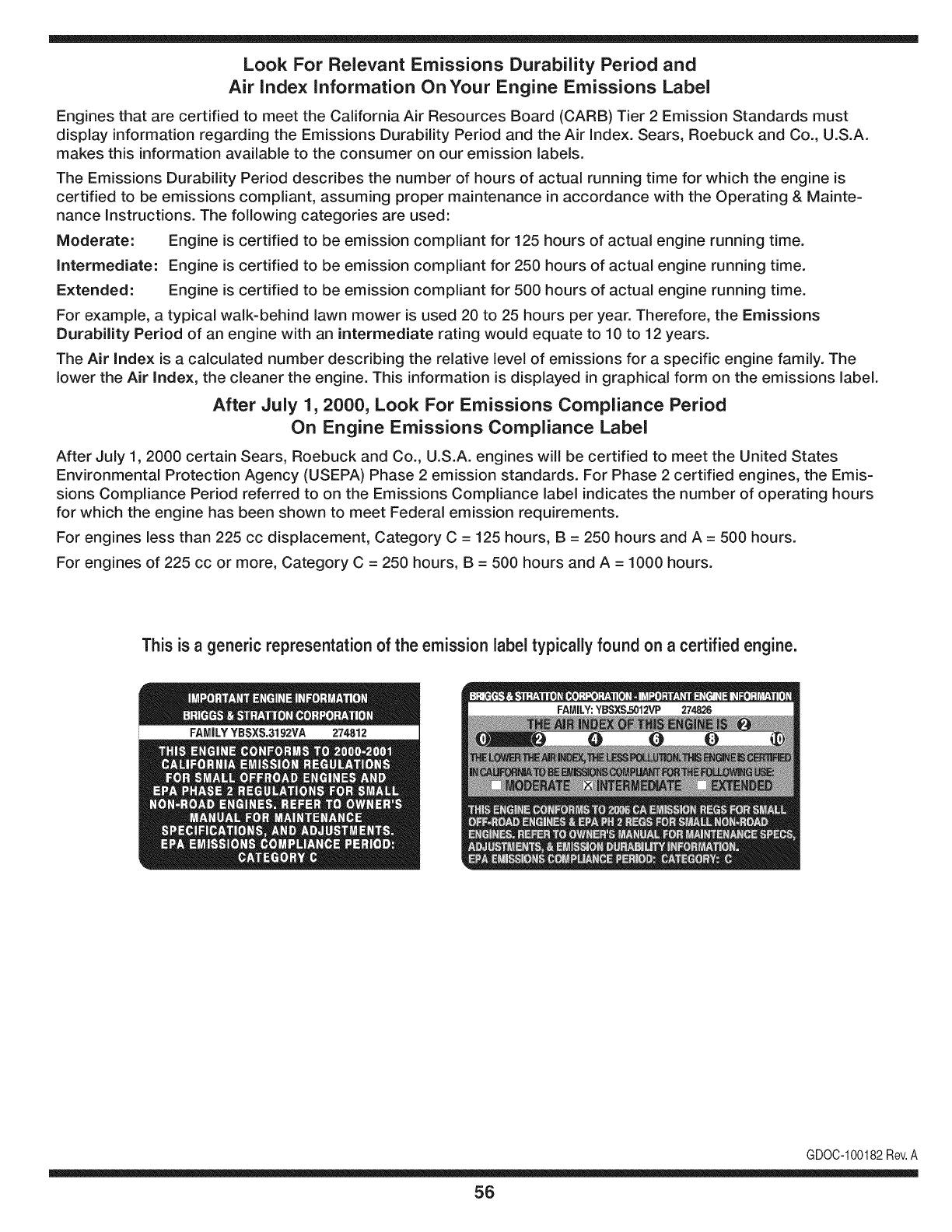
Look For Relevant Emissions Durability Period and
Air index information On Your Engine Emissions Label
Engines that are certified to meet the California Air Resources Board (CARB) Tier 2 Emission Standards must
display information regarding the Emissions Durability Period and the Air Index. Sears, Roebuck and Co., U.S.A.
makes this information available to the consumer on our emission labels.
The Emissions Durability Period describes the number of hours of actual running time for which the engine is
certified to be emissions compliant, assuming proper maintenance in accordance with the Operating & Mainte-
nance Instructions. The following categories are used:
Moderate: Engine is certified to be emission compliant for 125 hours of actual engine running time.
Intermediate: Engine is certified to be emission compliant for 250 hours of actual engine running time.
Extended: Engine is certified to be emission compliant for 500 hours of actual engine running time.
For example, a typical walk-behind lawn mower is used 20 to 25 hours per year. Therefore, the Emissions
Durability Period of an engine with an intermediate rating would equate to 10 to 12 years.
The Air Index is a calculated number describing the relative level of emissions for a specific engine family. The
lower the Air Index, the cleaner the engine. This information is displayed in graphical form on the emissions label.
After July 1,2000, Look For Emissions Compliance Period
On Engine Emissions Compliance Label
After July 1, 2000 certain Sears, Roebuck and Co., U.S.A. engines will be certified to meet the United States
Environmental Protection Agency (USEPA) Phase 2 emission standards. For Phase 2 certified engines, the Emis-
sions Compliance Period referred to on the Emissions Compliance label indicates the number of operating hours
for which the engine has been shown to meet Federal emission requirements.
For engines less than 225 cc displacement, Category C = 125 hours, B = 250 hours and A = 500 hours.
For engines of 225 cc or more, Category C = 250 hours, B = 500 hours and A = 1000 hours.
This is ageneric representation of the emission label typically found on a certified engine.
FAMILYYBSXS.3192VA 274812
GDOC-100182Rev.A
56
Congratulationson makinga smart purchase.YournewCraftsman®
productis designedandmanufacturedfor yearsof dependableopera-
tion.But likeall products,it mayrequirerepairfromtimeto time.That's
whenhavinga RepairProtectionAgreementcan saveyoumoneyand
aggravation.
Here'swhatthe RepairProtectionAgreement*includes:
* Expert service byour 10,000professionalrepairspecialists
* Unlimited service and no charge for partsand laboronall
coveredrepairs
* Product replacement upto $1500ifyourcoveredproductcan'tbe
fixed
*Discountof 10%from regularpriceof serviceand relatedinstalled
partsnotcoveredby theagreement;also,10%off regularpriceof
preventivemaintenancecheck
* Fast help by phone- we call itRapidResolution- phonesupport
froma Searsrepresentative.Thinkof usas a "talkingowner's
manual."
Once youpurchasethe Agreement,a simplephonecall isall thatit
takesfor youto scheduleservice.Youcan call anytimedayor night,or
schedulea serviceappointmentonline.
The RepairProtectionAgreementisa risk-freepurchase.Ifyou cancel
for any reasonduringthe productwarrantyperiod,wewill providea full
refund.Or,a proratedrefundanytimeafterthe productwarrantyperiod
expires.Purchaseyour RepairProtectionAgreementtoday!
Some limitations and exclusionsapply. For prices and additional
informationin the U.S.A.call 1-800-827-8855.
*Coverage inCanadavaries on some items.For full details call
Sears Canada at 1-800-381-8665.
Sears Installation Service
ForSearsprofessionalinstallationof homeappliances,garagedoor
openers,waterheaters,andothermajorhomeitems,inthe U.S.A.or
Canadacall 1-800-4-MY-HOME®.
57
Declaraci6n de garantia ............................ Pagina 58
Practicas operaci6n seguras ..................... Pagina 59
Montaje ...................................................... Pagina 65
Piezas de repuesto estandar y archivos adjuntos ..
................................................................... Pagina 10
Operaci6n .................................................. Pagina 66
Servicio y Mantenimiento .......................... Pagina 74
Almacenamiento fuera de temporada ....... Pagina 87
Soluci6n de problemas .............................. Pagina 88
Acuerdo de protecci6n para reparaciones .... Pagina 93
Etiquetas de seguridad .............................. Pagina 9
Lista de piezas ........................................... Pagina 32
NOmero de servicio ................................... Cubierta
Posterior
Craftsman de Garantia integro
Cuandose operadoy rnantienendeacuerdocontodaslas instruccionessurninistradas,si no fungiblescualquierpartede esteequipode
equitaci6nfalladebidoa undefectode materialo rnanodeobradentrodedos a_osa partirde la fechao la cornpra,Ilarne1-800-659-5917para
organizarde forrnagratuitaen lacasade reparaci6n.
El marcoy el ejedelanteroser_reparadosin cargopor unperiododecincoa_osa partirde la fechade cornpraen casodedefectosdematerial
o rnanodeobra.
TodoIo anteriorla coberturade la garanfiase aplicaa s61o90 diasa parfir dela fechade cornprasi el equipoestAsiemprea caballoufilizado
paraprop6sitoscornercialesode alquiler.
Entodosloscasos,si la reparaci6nresultairnposible,elequipode equitaci6nserAsustituidodeforrnagratuitacon el rnisrnornodeloo uno
equivalente.
La bateriase sustituyedeforrnagratuitadurante90dias a partirde lafechadecornpraencasode defectosde materialo rnanodeobra
(nuestraspruebasdernuestranquenova a celebrarun cargo).
Esta garantia cubre_nicamente defectos de material y mano de obra.Sears no pagar_pot:
• FungiNesquese gastadoduranteel usonormal,incluyendoperonolirnitadoalas hojas,bujias,lirnpiezadeair& correas,filtrosy aceite.
• Norrnade serviciosde rnantenirniento,carnbiosde aceite,o sintonice-ups.
• Tire lasustituci6no reparaci6ndepinchazoscausadosporobjetosdesdeel exterior,comoporejemploclavos,espinas,los tocones,o de
vidrio.
• Carnbiode neurn&ticoso ruedasde sustituci6no reparaci6ncornoconsecuenciadedesgastenormal,accidentes,o rnalfuncionarnientoo
rnantenirniento.
• Reparacionesquesean necesariasacausadelos abusosdeloperador,incluyendoperonolirnitadoa losdaSoscausadospor rernolcar
objetosrn&sall&dela capacidadde rnontarel equipo,afectana losobjetosquedoblarel marcoo elcig(Je_al,oel excesode velocidaddel
motor.
• Reparacionesquesean necesariasacausadela negligenciadel operador,incluyendoperonolirnitadoa, el_ctricosy rnec&nicosde los
da_oscausadospor elalrnacenarnientoinadecuado,faltade utilizaci6nde lacategoriaapropiaday lacantidaddeaceitedemotor,el
fracasopararnantenerla cubiertaclarade losdesechosinflarnables,o el fracasopararnantenerla equitaci6nequipode acuerdoalas
instruccionesquefiguranen elmanualdeloperador.
• Motor(sisternadecombustible),la lirnpiezao reparacionescausadasporcombustibledeterrninadopuedanestarcontarninadoso oxidado
(rancio).Engeneral,el combustibledebeserutilizadodentrode los 30dias siguientesa su fechadecornpra.
• Normaldesgastey deteriorodelos acabadosexteriores,o la etiquetadel productode reernplazo.
Estagaranfias61otendrAvalidezrnientrasel productose utiliceen los EstadosUnidos.
Estagaranfialeotorgaderechoslegalesespedficos,peroustedpodriagozarde otrosderechosen raz6nde su lugarde residencia.
Sears, Roebuck and Co., Hoffman Estates, IL 60179
Aceitedel motor: SAE30
Combustible: Gasolinasin plorno
Bujia: Champion®RC12YC
Motor: Briggs& StrattonPlatinoV-Twin
NSmerode modelo ..........................................................
N_merode serie ..............................................................
Fechade compra .............................................................
RegistrearribaelnQrnerodel rnodelo,elnQrnerode seriey lafecha
decornpra
©SearsBrands,LLC 58
Lapresenciadeeste sirnboloindicaque setratade instrucciones
irnportantesde seguridadquese debenrespetarparaevitar
ponerenpeligrosu seguridadpersonaly/o materialy lade otras
personas.Leay siga todaslas instruccionesdeestemanualantes
de poneren funcionarnientoestarn_.quina.Si no respetaestas
instruccionespodriaprovocarlesionespersonales.Cuandoveaeste
sirnbolo,ipresteatenci6na la advertencia!
PROPOSICION 65 DE CALIFORNIA
Elescapedel motordeesteproducto,algunosde suscornponentes
y algunoscornponentesdelvehiculocontieneno liberansustancias
quirnicasqueelestadodeCaliforniaconsideraque puedenproducir
c_.ncer,defectosde nacirnientouotrosproblernasreproductivos.
Losbornesdela bateriay los accesoriosdines contienenplornoy
cornpuestosde plorno,sustanciasquirnicasque seg_nIo estableci-
do pot el Estadode Californiacausanc_.ncery da_osenel sisterna
reproductivo.Ldveselas manos despu_sde estaren contacto
con estoscomponentes.
Estarn_.quinarueconstruidaparaseroperadadeacuerdocon
las reglasde seguridadcontenidasenestemanual.AI igualque
concualquiertipo deequipornotorizado,undescuidoo error por
partedeloperadorpuedeproducirlesionesgraves.Estarn_.quina
es capazde arnputarrnanosy piesy dearrojarobjetoscon gran
fuerza.Deno respetarlas instruccionesde seguridadsiguientesse
puedenproducirlesionesgraveso larnuerte.
Su responsabilidad--Restrinja el usode estarn_.quina
rnotorizadaalas personasque lean,cornprendany respetenlas
advertenciase instruccionesqueaparecenen estemanualyen la
rn_.quina.
iGI.IARI)E ESTASINSTRUCCIONES!
FUNCIONAIVIIENTO GENERAL
•Lea,entienday curnplatodaslas instruccionesincluidasen
la rn_.quinayen los rnanualesantesdernontarlay utilizarla.
Guardeestemanualenun lugarseguroparaconsultasfuturasy
peri6dicas,asi cornoparasolicitarrepuestos.
•Farniliaricesecontodoslos controlesy con el usoadecuado
delos rnisrnos.Sepac6rnodetenerlarn_.quinay desactivarlos
controlesr_.pidarnente.
• No perrnitanuncaque los ni_osrnenoresde 14a_osutilicen
estarn_.quina.Los ni_osde 14a_osen adelantedebenleery
entenderlas instruccionesde operaci6ny norrnasdeseguridad
contenidaseneste manual,y en la rn_.quinay debenser
entrenadosy supervisadospor unadulto.
• Nuncaperrnitaquelos adultosoperenestarn_.quinasin recibir
antesla instrucci6napropiada.
• Paraayudaraevitarel contactocon las cuchillaso unalesi6npor
algQnobjetoquesea arrojado,rnantengaa los observadores,a
los ayudantes,ni_osy rnascotasalejadosal rnenos25 metrosde
la rn_.quinarnientrasest,.en funcionarniento.Detengala rn_.quina
si alguienentraen lazona.
• Inspeccionerninuciosarnenteel Areadondeutilizar_,el equipo.
Retiretodaslas piedras,palos,cables,huesos,juguetesy otros
objetosextra_osquepodrianser recogidosy arrojadospor la
acci6nde las cuchillas.Losobjetosarrojadospor larn_.quina
puedenproducirlesionesgraves.
• Planifiqueel patr6ndecortedelc_spedque hade seguirpara
evitarla descargade materialhacialoscarninos,las veredas,los
observadores,etc.Eviteadern_.sdescargarmaterialcontralas
paredesy obstruccionesquepodrianprovocarqueel material
descargadorebotecontrael operador.
• Paraprotegerselos ojos utilicesiernpreanteojoso antiparras
deseguridadrnientrasoperalarn_.quinao rnientraslaajusta
o repara.Losobjetosarrojadosque rebotanpuedenproducir
lesionesocularesgraves.
• Utilicezapatosde trabajoresistentes,desuelafuerte,asi corno
pantalonesy carnisasajustados.Las prendassueltaso las
alhajaspuedenquedaratrapadasenlas piezasrnovibles.Nunca
operela rn_.quinadescalzoo con sandalias.
• Est_atentoa lacortadoray a la direcci6nde la descargade
losaditarnentosy noapuntea nadie.Nuncaoperelacortadora
de c_spedsin queest_nen su lugarapropiadolacubiertade
descargao elcolectorde recortesdecesped.
• Nopongalasrnanoso lospies cercade las piezasrotatoriaso
debajode la plataforrnadecorte. Elcontactocon las cuchillas
puedeproducirla arnputaci6ndernanosy pies.
• Unacubiertade descargafaltanteo da_adapuedeprovocarel
contactocon lacuchillao lesionespot objetosarrojados.
• Detengala(s)cuchilla(s)cuandoatraviesesenderos,sendaso
carninosde gravay cuandonoest_cortandoel cesped.
• Vigileel tr_.nsitovehicularcuandoest_operandocercadeo en
crucesde carninos.Estarn_.quinanodebeutilizarseen lavia
pQblica.
• Noopereestarn_.quinabajolosefectosdelalcoholode drogas.
• Corteel cespedsolarnentecon luzdediao conunabuenaluz
artificial.
• Nuncatransportepasajeros.
• Desenganchela(s)cuchilla(s)antesdecolocarlarnarchaatr_.s.
Retrocedalentarnente.Siernpremirehaciaabajoy haciaatr_.santes
y rnientrasretrocede,paraevitaraccidentes.
• Reduzcala velocidadantesdedarlavuelta.Operelarn_.quina
suavernente.Evitelaoperaci6nerr_.ticay la velocidadexcesiva.
• Desenganchela(s)cuchilla(s),coloqueelfrenodeestaciona-
rniento,detengaelmotory esperehastaquela(s)cuchilla(s)se
detenga(n)porcornpletoantesderetirarelcolectordec_sped,
vaciarlos recortes,destaparelcanal,retirarrestosde cespedo
desechos,o hacercualquierajuste.
59
• Nuncadejelarn_.quinaen funcionarnientosinvigilancia.Apague
siernprelascuchillas,coloqueelfrenodernano,detengaelmotory
retirela Ilaveantesdebajarsedelvehiculo.
• Tengasurnocuidadoalcargaro descargarlarn_.quinaen un
rernolqueocarni6n.Estaunidadnodebeconducirseenascensoo
descensoderarnpas,porquepodrialadearsey provocarlesiones
personalesgraves.Enlas rarnpaslarn_.quinasedebeernpujar
rnanualrnenteparacargarlao descargarlacorrectarnente.
• Elsilenciadory el motorse calientany puedencausarquernaduras.
Nolos toque.
• Reviseel espaciolibrepot encirnade lacabezaantesdeconducir
bajolas rarnasbajasde_.rboles,cables,cerrarnientosde puertas,
etc.enloscualeseloperadorpodriaatorarseo serernpujadofuera
dela rn_.quina,Ioquepodriaresultaren lesionesgraves.
• Desenganchetodoslosernbraguesdelos accesoriosy presione
totalrnenteel pedaldelfrenoantesdeintentararrancarel motor.
• Larn_.quinaest,.diseSadaparacortarc_spedresidencialnormal,
conunaalturanomayora 10".Nointentecortarcespeddernasiado
crecido,seco(porej.,pastura)nipilasdehojassecas.Elc_sped
y las hojassecaspuedenentrarencontactoconel escapedel
motory/o acurnularseenla plataforrnade lacortadoradecesped,
convirti_ndoseen unpeligrodeincendio
• Utilicesolarnenteaccesoriosy aditarnentosaprobadosparaesta
rn_.quinapot elfabricantedelarnisrna.Lea,cornprenday siga
todaslasinstruccionesproporcionadasconlosaccesorioso
aditarnentosaprobados.Paraobtenerunalistadelosaccesorios
aprobadosy losarchivosadjuntos,Ilarne1-800-659-5917.
• Losdatosestadsticosrnuestranquelosoperadoresde60 aSos
y rnayoresseven involucradosenunaltoporcentajedelesiones
relacionadascontractorescortacesped.Estosoperadoresdeben
evaluarsu capacidadparaoperarel tractorcortac_spedenforrna
suficienternenteseguraparaprotegersea ellosrnisrnosy alos
dern_.scontralesionesgraves.
Si se presentansituacionesqueno est_.nprevistasen este
manualsea cuidadosoy use el sentidocornQn.Contacto1-800-
659-5917parainforrnaci6ny asistencia.
FUNCIONAiVlIENTO EN PENDIENTES
Las pendientesson unfactorirnportanterelacionadoconaccidentes
porderrapey vuelcosquepuedenproducirlesionesgravese incluso
la rnuerte.Laoperaci6nen pendientesrequieremayorprecauci6n.
Si nopuederetrocederen la pendienteo si no se sienteseguro,no
realiceningunaoperaci6ndecorte.
Parasu seguridad,use el indicadordependientesquese incluye
cornopartede estemanualpararnedirla pendienteantesdeoperarla
rn_.quinaenunazonainclinada.Sila pendientees mayorde 15grados
segQnel rnedidor,noopereestarn_.quinaenese sector,puespodria
causarlesionesgraves.
HagaIo siguiente:
•Podehaciaarribay abajodelas pendientes,nodeforrnatrans-
versal.Tengacuidadocuandocarnbiededirecci6nal operaren
pendiente.
• Est_atentoa loshoyos,surcos,baches,rocas,uotrosobjetos
ocultos.Elterrenodesniveladopuedevoltearla rn_.quina.Elcesped
altopuedeocultarobst_.culos.
Vayaa bajavelocidad.ElijaunavelocidadIosuficienternentebaja,
de rnodoquenotengaquedetenerseohacercarnbiosrnientras
est,.sobrela pendiente.Losneurn_.ticospodrianperdertracci6n
sobrelaspendientesaQncuandolosfrenosfuncionaranapro-
piadarnente.Siernprernantengalarn_.quinaen carnbiornientras
desciendelaspendientes,parapoderfrenarconel motor.
• Sigalas recornendacionesdelfabricanteparalos pesoso contra-
pesosdelas ruedas,pararnejorarlaestabilidaddelarn_.quina.
Pararecornendaciones,Ilarneal 1-800-659-5917.
• Tengaespecialcuidadocon loscolectoresdecespeduotros
aditarnentos.Losrnisrnospuedenrnodificarlaestabilidaddela
rn_.quina.
• Hagaquetodoslos rnovirnientosen laspendientesseanlentosy
graduales.Nocarnbierepentinarnentelavelocidadnila direcci6n.
Unfrenadoo carnbiodevelocidadrepentinospuedencausarque
el frentede larn_.quinase levantey d_unavolteretahaciaatr_.s,Io
quepodriaproducirlesionesgraves.
• Evitearrancaro detenerseenunapendiente.Silosneurn_.ticos
pierdenlatracci6n,desenganchelascuchillasy descienda
lentarnentela pendiente.
No hagaIo siguiente:
•Nogiresobrelas pendientesarnenosqueseanecesario.Sies
posible,girelentarnentey gradualrnenteduranteeldescenso.
• Nocorteelc_spedcercade pozos,hundirnientosoterraplenes.La
cortadoradec_spedpuedevolcarserepentinarnentesiunade las
ruedasest,.sobreelhordede unacantilado,zanjao siunhordese
desrnorona.
• Nointenteestabilizarlarn_.quinaponiendoelpieenel suelo.
• Noutiliceuncolectordecespeden pendientesernpinadas.
• Nopodeelcespedh_rnedo.Unarnenortracci6npodriacausar
derrapes.
• Noparadescender.Elexcesodevelocidadpuedehacerqueel
operadorpierdaelcontroldela rn_.quina,ocasionandolesiones
graveseinclusolarnuerte.
• Norernolquecargaspesadasdetr_.sdelosaditarnentos(carritode
basuracargado,podadoraderodillos,etc)en pendientesrnayores
de5grados.Cuandosedesplazapendienteabajo,el pesoadicional
tiendeaernpujareltractory puedehacerquese pierdaelcontrol
delrnisrno(porejernplo,eltractorsepuedeacelerar,se reducela
capacidadparafrenary rnaniobrar,losaccesoriospuedenplegarse
cornouncortaplurnasy hacerqueeltractorvuelque).
NINOS
Puedenocurriraccidentestr_.gicossi el operadornoest,.atentoa la
presenciade niSos.PotIo general,los niSosse sientenatraidospor
estetipo de rn_.quinasy su funcionarniento.Noentiendenlos riesgos
ni los peligros.Nuncaasurnaquelos niSosperrnanecer_.nen el rnisrno
lugardondelosvio pot Qltirnavez.
• Mantengaa losniSosfueradel_.readetrabajoy bajoestricta
vigilanciadeunadultoresponsableadern_.sdelpropiooperador.
Est_alertay apaguela rn_.quinasiunniSoingresaal_.rea.
• Antesy rnientrasest,.retrocediendo,mirehaciaatr_.sy cuidequeno
hayaniSos.
NuncatransporteniSos,aQnconlacuchillaapagada.Podriancaerse
y resultarseverarnenteheridoso interferirconlaoperaci6nsegurade
la rn_.quina.
Tengaextrernaprecauci6ncuandoseaproxirneaesquinasciegas,
portales,arbustos,_.rbolesuotrosobjetosquepuedanirnpedirlever
a unniSoquesecruceenel recorridode larn_.quina.
6O
• Paraevitaraccidentesaloperarenrnarchaatr_.s,siernpredesengan-
chelascuchillasantesdecolocarrnarchaatr_.s.Siest,.instalado,
el"ModoPrecaucidnMarchaAtr_.s"(hojasdeoperarlarn_.quina,
rnientrasquelospaseosala inversa)nodebeutilizarsecuandohay
ni_osuotraspersonaspresentes.
• Mantengaa losni_osalejadosdelosrnotoresenrnarchao calientes.
Puedensufrirquernadurasconunsilenciadorcaliente.
• RetirelaIlavecuandodejelarn_.quinasinvigilancia,evitequeuna
personasinautorizaci6nlarnaneje.
No perrnitanuncaque los ni_osrnenoresde 14a_osutilicenesta
rn_.quina.Losni_osde 14a_osen adelantedebenleery entenderlas
instruccionesdeoperaci6ny norrnasde seguridadcontenidaseneste
manual,yen la rn_.quinay debenserentrenadosy supervisadospor
unadulto.
REIVIOLQUE
• Rernolque_nicarnenteconunarn_.quinaquecuenteconun
enganchediseSadopararernolcar.Noacopleequiporernolcado
exceptoenelpuntodeenganche.
• SigalasrecornendacionesdelfabricanteenIoquerespectaalos
lirnitesdepesodelosequiposa rernolcary alrernolqueenpendien-
tes.Pararecornendaciones,Ilarneal 1-800-659-5917.
• Nuncaperrnitala presenciade niSosuotraspersonasdentroosobre
losequiposrernolcados.
• Enlaspendientes,elpesodelequiporernolcadopuedecausar
p_rdidadetraccidny perdidadecontrolde larn_.quina.
• Siernpreuseextralaprecauci6nrernolcandoconunarn_.quina
capazdehacervueltasapretadas(p.ejpaseo"devueltacero"-enel
cortacesped).Hagaarnpliasvueltasparaevitaralgato-knifing.
• Despl_.ceselentarnentey dejedistanciaadicionalparafrenado.
• Noparadescender.
SERVIClO
Manejo seguro de la gasolina
Paraevitarlesionespersonaleso daSosrnaterialessea surnarnente
cuidadosoal rnanipularla gasolina.Lagasolinaes surnarnente
infiarnabley susvaporespuedencausarexplosiones.Se puede
lesionargravernentesi derrarnagasolinasobreustedo sobrela ropa,
ya que_stase puedeincendiar.L_.vesela piely c_.rnbiesede ropade
inrnediato.
• Utilices61olos recipientesparagasolinaautorizados.
• NuncaIlenelos recipientesenel interiorde unvehiculoo carnidn
o cajade rernolquecon recubrirnientopl_.stico.Coloquesiernpre
los recipientesenel piso y lejosdel vehiculoantesde realizarla
carga.
• Cuandoseafactible,retireel equipoa gasolinadel carni6no
rernolquey II_neloen elsuelo.Siestonoes posible,Ileneel
equipoen unrernolqueconun contenedorport_.til,envezde
hacerlocon unaboquilladispensadoradegasolina.
• Mantengala boquillade Ilenadoencontactoconel hordedel
dep6sitode combustibleocon la aberturadel recipienteen todo
rnornento,hastaterrninarlacarga.No utiliceundispositivode
boquilladeapertura/cierre.
• Apaguetodosloscigarrillos,cigarros,pipasy otrasfuentesde
cornbustidn.
• Nuncacarguecombustibleenla rn_.quinaenun espaciocerrado.
• Nuncasaquela tapadel combustibleniagreguecombustible
rnientrasel motorest,.calienteo enrnarcha.Dejequeel motor
seenfrie porIornenosdos rninutosantesde volvera cargar
combustible.
• NuncaIleneen excesoel dep6sitode combustible.Lleneel
tanquenorn_.sde 1/2pulgadapordebajode labasedel cuello
del tap6ndecarga,paradejarespacioparalaexpansi6ndel
combustible.
• Vuelvaa colocarlatapa dela gasolinay ajQstelabien.
• Lirnpieel combustiblequese hayaderrarnadosobreel motory el
equipo.Trasladelarn_.quinaa otrazona.Espere5 rninutosantes
de encenderelmotor.
• Parareducirel riesgode incendio,rnantengala rn_.quinalirnpia
de pasto,hojasy deacurnulacidndeotros residuos.Lirnpielos
derrarnesdeaceiteo combustibley saquetodoslos residuos
ernbebidosde combustible.
• Nuncaguardelarn_.quinao el recipientedecombustibleen un
espaciocerradodondehayafuego,chispaso luz piloto,corno
porejernplodecalentadoresdeagua,calefactoresde arnbientes,
hornos,secadoresde ropau otrosaparatosa gas.
• Dejequelarn_.quinase enfriecincorninutospor Iornenosantes
de guardarla.
Servicio general
•Nuncaenciendael motoren espacioscerradosoen unazona
con pocaventilacidn.Elescapedel motorcontienernondxidode
carbono,ungas inodoroy letal.
• Antesdelirnpiar,repararo inspeccionarla rn_.quina,cornpruebe
que la(s)cuchilla(s)y todaslas partesenrnovirnientose hayan
detenido.Desconecteel cablede la bujfay p6ngalohaciendo
rnasacontrael motorparaevitarquese enciendaaccidental-
rnente.
• Reviseperi6dicarnenteparaasegurarsequelas cuchillasse
detenganporcornpletoenaproxirnadarnentecinco(5) segundos
despu_sdeaccionarel controldedesenganchede la(s)
cuchilla(s).Si las cuchillasnose detienendentrodeeste lapso
de tiernpo,su unidaddeber_,ser reparadaporsu distribuidorde
servicioautorizadoMTD.
• Reviseconfrecuenciaelfuncionarnientodelsisternadefrenos
ya queest,.sujetoa desgasteporla operaci6nnormal.Ajustey
efectQernantenirnientosegQnse requiera.
61
• Reviselos pernosdemontajedela(s) cuchilla(s)y del motora
intervalosfrecuentesparaverificarqueest_nbienapretados.
Adem_.s,inspeccionevisualmentela(s) cuchilla(s)en buscade
daSos(porejemplo,desgasteexcesivo,abolladuras,rajaduras,
etc.). Reemplacela(s)cuchilla(s)Qnicamentecon lascuchillas
defabricantesde equiposoriginales(O.E.M.)listadasen este
manual.Elusode piezasquenocumplencon las especifi-
cacionesdelequipooriginalpodriatenercomoresultadoun
rendimientoincorrectoy adem_.sponeren riesgola seguridad.
• Lascuchillasdelas podadorassonmuyafiladas.Envuelvala
cuchillao utiliceguantesy extremelasprecaucionescuando
efectQemantenimiento.
Mantengatodoslos pernos,tuercasy tornillosbienajustados
paraasegurarsede quela m_.quinase encuentraen condiciones
segurasde operaci6n.
• Nuncaaltereel sistemade enclavamientode seguridadni
otrosmecanismosde seguridad.Controleperi6dicamenteque
funcionencorrectamente.
Despu_sdegolpearcon algQnobjetoextraSo,detengael motor,
desconecteelcablede la bujfay conecteel motora masa.
Inspeccioneminuciosamentela m_.quinaparaver si est,.daSada.
Repareel daSoantesdearrancary ufilizarla m_.quina.
Nuncatratedehacerajusteso reparacionesa lam&quina
mientrasel motorest&enmarcha.
• Loscomponentesdel colectordec_spedy la cubiertade
descarga,estansujetosa desgastey daSosque podriandejar
expuestaspartesen movimientoo permifirque searrojenobjetos.
Paraprotegersuseguridad,verifiquefrecuentementetodoslos
componentesy reempl_.celosinmediatamentes61ocon piezasde
los fabricantesdel equipooriginal,listadosen estemanual.Eluso
de piezasque nocumplencon las especificacionesdel equipo
originalpodriatenercomoresultadoun rendimientoincorrectoy
adem_.sponeren riesgola seguridad.
• Nocambielaconfiguraci6ndel reguladordel motorni Ioopere
a sobrevelocidad.El reguladordel motorcontrolala velocidad
m_.ximaseguradefuncionamientodel motor.
• Mantengao reemplacelasefiquetasde seguridade instrucciones
segQnseanecesario.
Respetelas normasreferentesa ladisposici6ncorrectay las
reglamentacionessobregasolina,aceite,etc. paraprotegerel
medicambiente.
• SegQnla Comisi6ndeSeguridadde Productosparael Consu-
midorde los EstadosUnidos(CPSC)y laAgenciade Protecci6n
Ambientalde los EstadosUnidos(EPA),esteproductotieneuna
vida Qtilmediade siete(7)aSos,6 270horasdefuncionamiento.
AIfinalizarla vidaOtilmedia,adquieraunam_.quinanuevao haga
inspeccionaranualmente_staSearsporunou otrodistribuidorde
serviciosparacerciorarsedequetodoslos sistemasmec_.nicos
y de seguridadfuncionancorrectamentey no tienenexcesivo
desgaste.Si noIo hace,puedenproducirseaccidentes,lesiones
o muerte.
NO MODIFIQUE EL MOTOR
Paraevitarlesionesgraveso lamuerte,nomodifiqueel motorbajo
ningunacircunstancia.Si cambialaconfiguraci6ndel reguladordel
motorel motorpuededescontrolarsey operara velocidadesinsegu-
ras.Nuncacambielaconfiguraci6ndef_.bricadel reguladordel motor.
AVlSO REFERIDO AEMISIONES
Losmotoresqueest_.ncertificadosy cumplencon las regulaciones
de emisionesfederalesEPAy de CaliforniaparaSORE(Equipos
peque_ostodoterreno)est_.ncertificadosparaoperarcongasolina
comQnsin plomoy puedenincluirlos siguientessistemasde control
de emisiones:Modificaci6nde motor(EM) y catalizadorde tresvias
(TWO)siest_.nequipadosde esa manera.
GUARDACHISPAS
EstamAquinaest,.equipadacon unmotorde combusti6ninternay
nodebeser utilizadaen o cercade unterrenoagrestecubiertopor
bosque,malezaso hierbaexceptosi el sistemade escapedelmotor
est,.equipadocon unamortiguadordechispasquecumplacon las
leyeslocaleso estatalescorrespondientes,encasode haberlas.
Si se utilizaunamortiguadorde chispasel operadorIo debemantener
en condicionesde usoadecuadas.Enel Estadode Californialas
medidasanteriormentemencionadassonexigidasporIcy (Arficulo
4442del C6digode RecursosPOblicosde California).Esposible
queexistanleyessimilaresenotrosestados.Lasleyesfederalesse
aplicanenterritoriosfederales.
Puedeconseguirelamortiguadordechispasparael silenciadora
travesdesu distribuidorautorizadode motoreso poni_ndoseen
contactoconel centrode servicioSears.
62
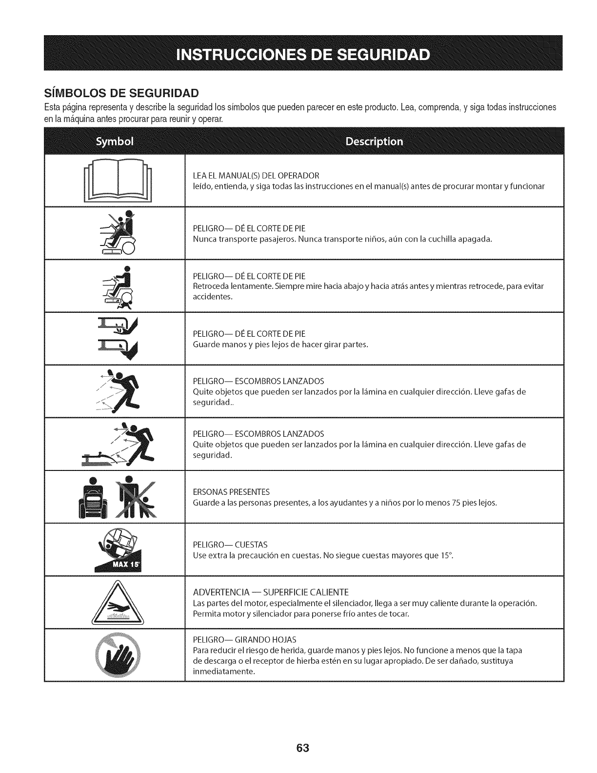
SilVlBOLOS DE SEGURIDAD
Estap&ginarepresentay describelaseguridadlos simbolosquepuedenpareceren esteproducto.Lea,comprenda,y sigatodasinstrucciones
enla m_quinaantesprocurarparareuniry operar.
0
J
AL
LEA EL MANUAL(S) DEL OPERADOR
leido, entienda, y siga todas las instrucciones en el manual(s) antes de procurar montar y funcionar
PELIGRO-- DE EL CORTE DE PIE
Nunca transporte pasajeros. Nunca transporte ni_os, aun con la cuchilla apagada.
PELIGRO-- DE EL CORTE DE PIE
Retroceda lentamente. Siempre mire hacia abajo y hacia atr_is antes y mientras retrocede, para evitar
accidentes.
PELIGRO-- DE EL CORTE DE PIE
Guarde manos y pies lejos de hacer girar partes.
PELIGRO-- ESCOMBROS LANZADOS
Quite objetos que pueden ser lanzados por la I_imina en cualquier direcci6n. Lleve gafas de
seguridad..
PELIGRO-- ESCOMBROS LANZADOS
Quite objetos que pueden ser lanzados por la I_imina en cualquier direcci6n. Lleve gafas de
seguridad.
ERSONAS PRESENTES
Guarde alas personas presentes, a los ayudantes y a ni_os por Io menos 75 pies lejos.
PELIGRO-- CUESTAS
Use extra la precauci6n en cuestas. No siegue cuestas mayores que 15°.
ADVERTENCIA-- SUPERFICIECALIENTE
Las partes del motor, especialmente el silenciador, Ilega a set muy caliente durante la operaci6n.
Permita motor y silenciador para ponerse frio antes de tocar.
PELIGRO-- GIRANDO HOJAS
Para reducir el riesgo de herida, guarde manos y pies lejos. No funcione a menos que la tapa
de descarga o el receptor de hierba est_n en su lugar apropiado. De ser dahado, sustituya
inmediatamente.
63
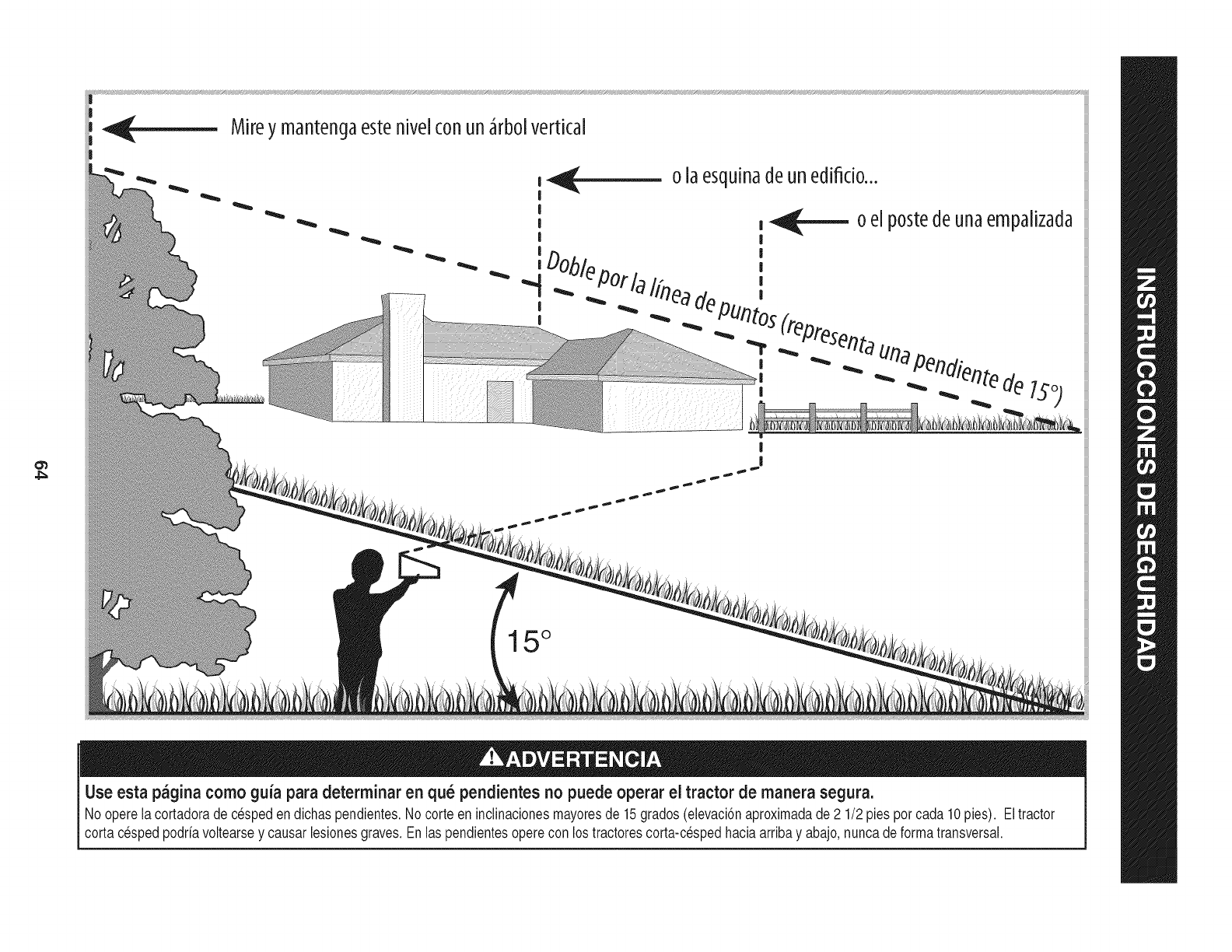
Mireymantenc3aestehive[conun_rbo[vertical
|
...|
15°
Use esta pagina como guia para determinar en qu_ pendientes no puede operar el tractor de manera segura.
No operelacortadoradec_speden dichaspendientes.No corteen inclinacionesmayoresde 15grados(elevaciSnaproximadade2 1/2pies porcada 10pies). Eltractor
cortac_spedpodrfavoltearsey causarlesionesgraves.Enlas pendientesoperecon lostractorescorta-cespedhaciaarribay abajo,nuncadeformatransversal.
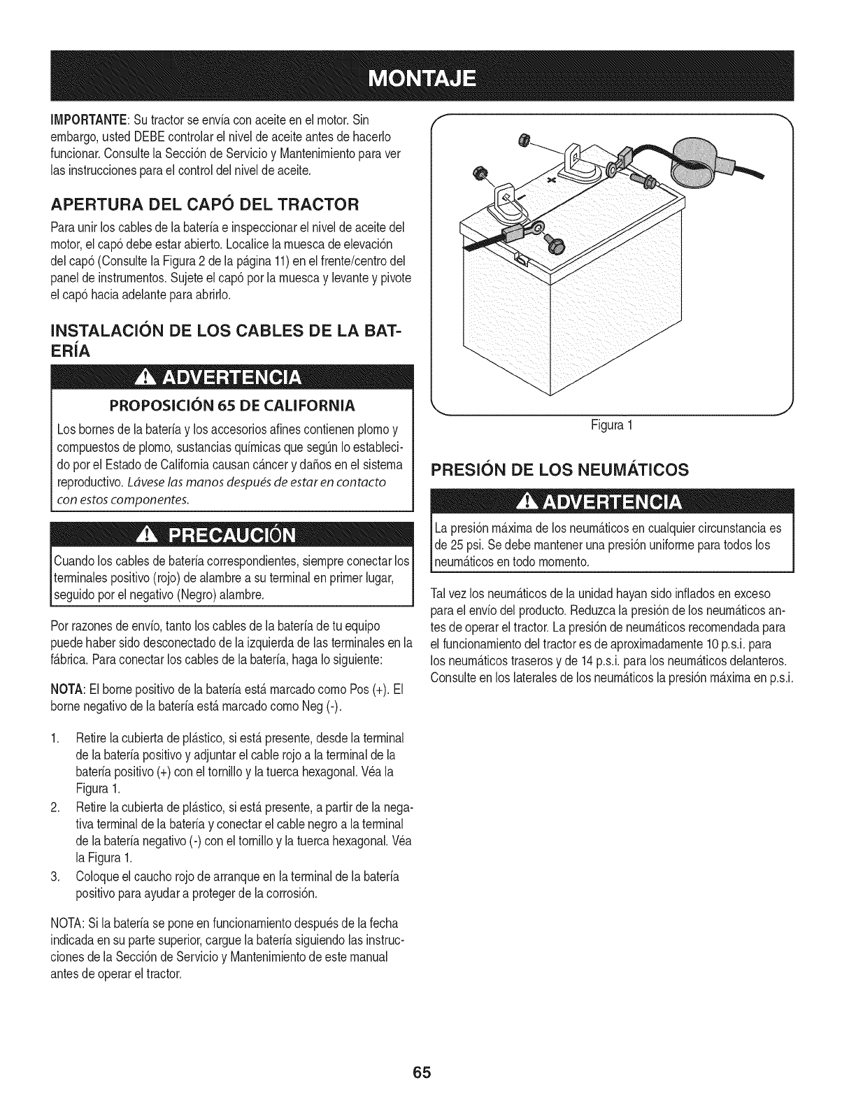
IMPORTANTE:Sutractorseenviaconaceiteenelmotor.Sin
embargo,ustedDEBEcontrolarelniveldeaceiteantesdehacerlo
fundonar.ConsultelaSecci6ndeServMoyMantenirnientoparaver
lasinstrucdonesparaelcontroldelniveldeaceite.
APERTURA DEL CAPO DEL TRACTOR
Paraunir loscablesde la bateriae inspeccionarel niveldeaceitedel
motor,el cap6debeestarabierto,Localicela rnuescadeelevad6n
delcap6 (ConsultelaFigura2 dela p_.gina11)enel frente/centrodel
panelde instrurnentos.Sujeteel cap6por larnuescay levantey pivote
elcap5 haciaadelanteparaabrNo,
INSTALACIC)N DE LOS CABLES DE LA BAT-
ER{A
PROPOSK:I()N 65 DE CALIFORNIA
Losbornesdela bateriay losaccesoriosafinescontienenplornoy
cornpuestosde plorno,sustanciasquirnicasqueseg0nIoestaNeci-
do porel EstadodeCaliforniacausanc_.ncery daSosenel sisterna
reproductivo.Ldveselas manos despu_sde estaren contacto
con estoscomponentes.
f
Figura1
PRESlC)N DE LOS NEUMATICOS
Cuandoloscablesdebateriacorrespondientes,siernpreconectarlos
terrninalespositivo(rojo)dealarnbrea su terminalenprimerlugar,
segudo pore negatvo (Negro)a arnbre. 1
Porrazonesde envio,tantoloscablesde labateriadetu equipo
puedehabersidodesconectadode laizquierdade lasterrninalesenla
f_.brica.Paraconectarlos cablesde la bateria,hagaIo siguiente:
NOTA:Elbornepositivodela bateriaest,. rnarcadocornoPos(+). El
bornenegativodela bateriaest,. rnarcadocornoNeg(-).
LapresiSnmaximade los neurn_.ticosen cualquiercircunstanciaes
de 25psi.SedebernantenerunapresiSnuniforrneparatodoslos
neurn_.ticosentodo rnornento.
Talvezlos neurn_.ticosdela unidadhayansidoinfiadosenexceso
parael enviodel producto.Reduzcala presiSnde losneurn_.ticosan-
tesde operarel tractor.LapresiSnde neurn_.ticosrecornendadapara
el funcionarnientodel tractores de aproximadarnente10p.s.i,para
los neurn_.ticostraserosy de 14p.s.i,paralos neurn_.ticosdelanteros.
Consulteen los lateralesde losneurn_.ticosla presiSnmaximaen p.s.i.
1. Retirela cubiertadepl_.stico,si est,.presente,desdelaterminal
de labater[apositivoy adjuntarel cable rojoa la terminalde la
bateriapositivo(+)con eltornilloy latuercahexagonal.Wa la
Figura1.
2. Retirela cubiertadepl_.stico,si est,.presente,a partirdela nega-
tivaterminaldela bateriay conectarel cablenegroa laterminal
de labaterianegativo(-) con eltornilloy latuercahexagonal.Wa
la Figura1.
3. Coloqueel cauchorojodearranqueen la terminalde la bateria
positivoparaayudara protegerde lacorrosiSn.
NOTA:Sila bateriase poneen funcionarnientodespu_sdela fecha
indicadaen su partesuperior,carguela bateriasiguiendolasinstruc-
cionesde la SecciSnde Servicioy Mantenirnientode estemanual
antesde operareltractor.
65
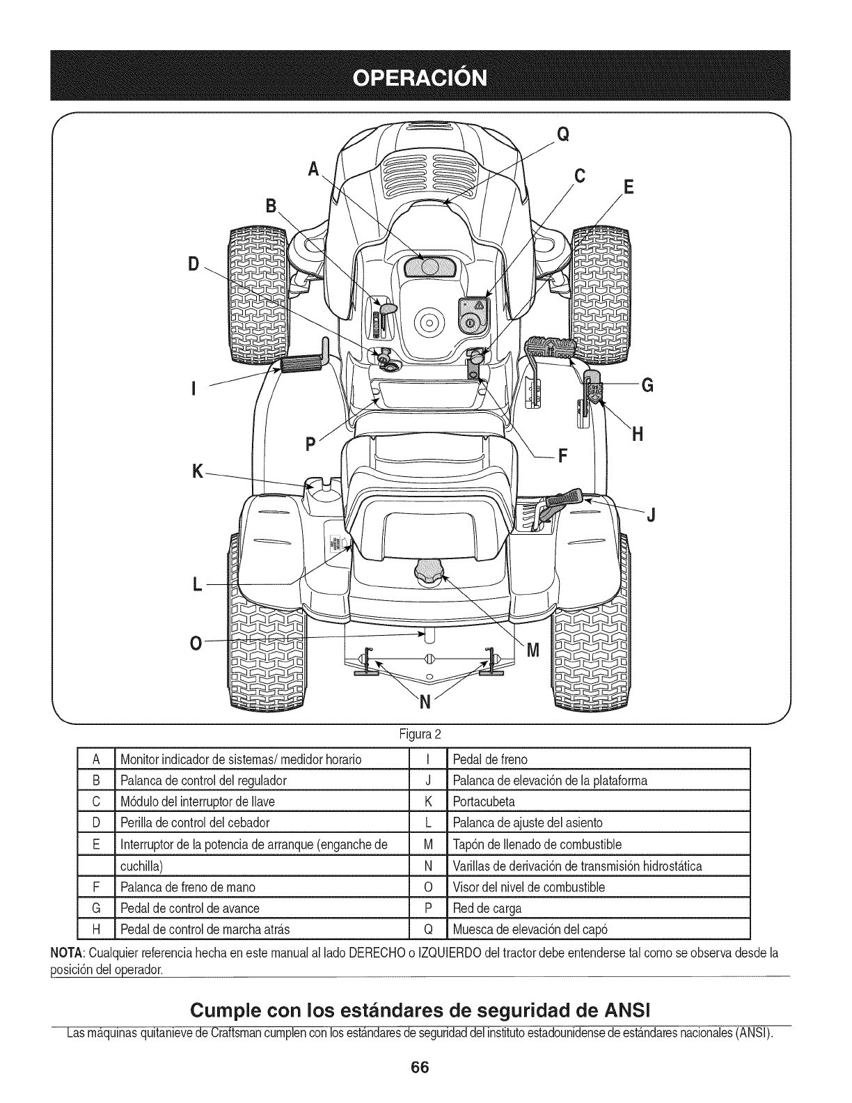
Q
A.. CE
D
P
L
Figura2
A Monitorindicadorde sistemas/medidorhorario I
B Palancade controldel regulador J
C M6dulodelinterruptordeIlave K
D Perillade controldelcebador L
E Interruptorde la potenciade arranque(enganchede M
cuchilla) N
F Palancade frenodemano 0
G Pedalde controlde avance P
H Pedalde controlde marchaatr_.s Q
Pedaldefreno
Palancadeelevaci6nde la plataforma
Portacubeta
Palancadeajustedel asiento
Tap6ndeIlenadode combustible
Varillasdederivaci6nde transmisi6nhidrost_.tica
Visordelnivelde combustible
Redde carga
Muescadeelevaci6ndel cap6
NOTA:Cualquierreferenciahechaenestemanualal lado DERECHOo IZQUIERDOdeltractordebeentendersetal comoseobservadesdela
posici6ndeloperador.
Cumple con los estandares de seguridad de ANSI
Lasm_,qulnasquitanievedeCraftsmancumplenconlosest_.ndaresdeseguridaddelinstitutoestadounidensedeest_.ndaresnacionales(ANSI).
66
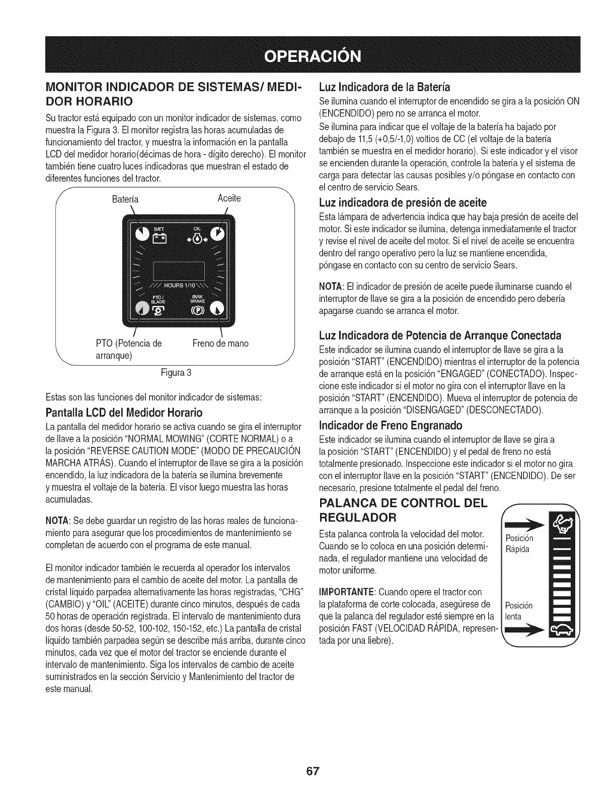
MONITOR INDICADOR DE SISTEMAS/MEDI-
DOR HORARIO
SutractorestAequipadocon unmonitorindicadorde sistemas,como
muestrala Figura3. Elmonitorregistralas horasacumuladasde
funcionamientodeltractor,y muestrala informacbnen la pantalla
LCDdel medidorhorario(d_cimasde hora- digito derecho).Elmonitor
tambi_ntienecuatrolucesindicadorasque muestranel estadode
diferentesfuncionesdeltractor.
/'_ Baterfa Aceite
PTO(Potenciade Frenode mano
arranque) j
Figura3
Estasson lasfuncionesdel monitorindicadorde sistemas:
Pantalla LCD del Medidor Horatio
La pantalladelmedidorhorariose activacuandosegirael interruptor
deIlavea la posici6n"NORMALMOWING"(CORTENORMAL)o a
la posici6n"REVERSECAUTIONMODE"(MODODE PRECAUCION
MARCHAATRAS).Cuandoelinterruptorde Ilavesegiraa laposici6n
encendido,laluz indicadoradela bateriase iluminabrevemente
y muestrael voltajede labateria.Elvisorluegomuestralas horas
acumuladas.
NOTA:Sedebeguardarunregistrodelas horasrealesdefunciona-
mientoparaasegurarque los procedimientosdemantenimientose
compietande acuerdocon el programade estemanual.
Elmonitorindicadortambi_nle recuerdaaloperadorlos intervalos
demantenimientoparael cambiodeaceitedelmotor.Lapantallade
cristalliquidoparpadeaalternativamentelas horasregistradas,"CHG"
(CAMBIO)y "OIL."(ACEITE)durantecincominutos,despu_sdecada
50horasde operaci6nregistrada.Elintervalode mantenimientodura
dos horas(desde50-52, 100-102,150-152,etc.) Lapantaiiade cristal
liquidotambi_nparpadeasegOnse describem_.sarriba,durantecinco
minutos,cadavezqueel motordeltractorse enciendeduranteel
intervaIode mantenimiento.Sigalos intervalosdecambiode aceite
suministradosen la secci6nServicioy Mantenimientodeltractorde
estemanual.
Luz Indicadorade la Bateria
Seiluminacuandoel interruptordeencendidose giraa la posici6nON
(ENCENDIDO)peronose arrancael motor.
Seiluminaparaindicarque elvoltajede la bateriaha bajadopor
debajode 11,5(+0,5/-1,0)voltiosde CO(elvoltajedela bateria
tambi_nse muestraenel medidorhorario).Sieste indicadory elvisor
seenciendendurantela operaci6n,controlelabaterfay el sistemade
carga paradetectarlas causasposibiesy/o p6ngaseen contactocon
el centrode servicioSears.
Luz indicadorade presi6n de aceite
EstaIAmparade advertenciaindicaquehay bajapresi6ndeaceitedel
motor.Siesteindicadorse iiumina,detengainmediatamenteeltractor
y reviseel niveldeaceitedel motor.Si el nivelde aceitese encuentra
dentrodel rangooperativoperola luzse mantieneencendida,
p6ngaseen contactocon su centrode servicioSears.
NOTA:El indicadordepresi6nde aceitepuedeiluminarsecuandoel
interruptorde Ilavesegira ala posici6ndeencendidoperodeberia
apagarsecuandosearrancael motor.
Luz Indicadorade Potenciade Arranque Conectada
Esteindicadorse iluminacuandoel interruptorde Ilavese giraa la
posici6n"START"(ENCENDIDO)mientrasel interruptorde la potencia
de arranqueest,.en la posici6n"ENGAGED"(CONECTADO).Inspec-
cloneesteindicadorsi elmotornogiracon el interruptorIlaveen la
posici6n"START"(ENCENDIDO).Muevael interruptordepotenciade
arranquea laposici6n"DISENGAGED"(DESCONECTADO).
Indicadorde Freno Engranado
Esteindicadorse iluminacuandoel interruptorde Ilavese giraa
laposici6n"START"(ENCENDIDO)y el pedalde frenonoest,.
totalmentepresionado.Inspeccioneesteindicadorsi el motornogira
con el interruptorIlaveen la posici6n"START"(ENCENDIDO).De ser
necesario,presionetotalmenteel pedaldelfreno.
PALANCA DE CONTROL DEL
REGULADOR
Estapaiancacontrolala velocidaddel motor.
Cuandose IocoIocaenunaposici6ndetermi-
nada,el reguiadormantieneunaveiocidadde
motoruniforme.
IMPORTANTE:Cuandoopereel tractorcon
laplataformade cortecoIocada,asegOresede
que lapalancadel reguiadorest_siempreen la
posici6nFAST(VELOCIDADR_,PIDA,represen-
tada porunaliebre).
67
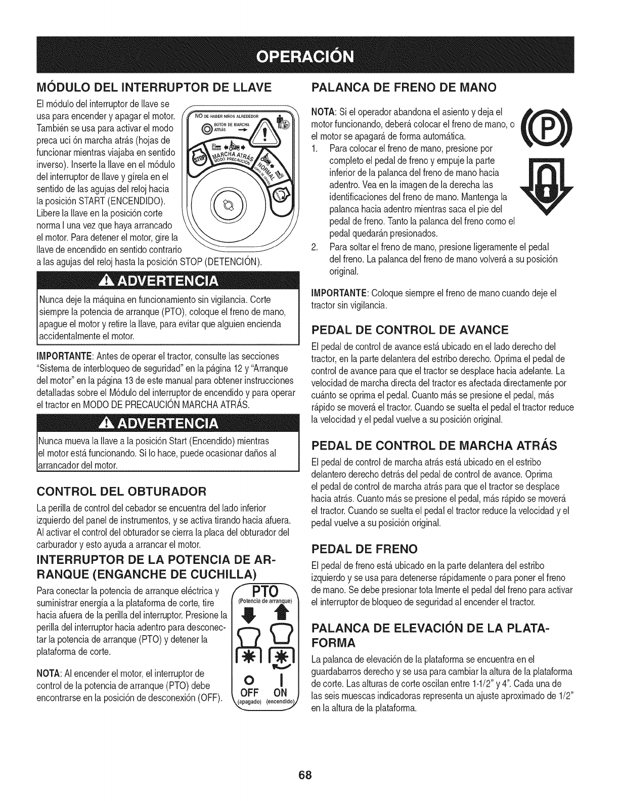
iVl6DULO DEL INTERRUPTOR DE LLAVE
El m6dulodelinterruptordeNavese l-
usa paraencendery apagarel motor. PN%-o........,...........
Tambi_nse usaparaactivarel modo @A,,A_
precauci 6n marchaatr&s(hojasde
funcionarmientrasviajabaensentido
inverso).Insertela Naveen el m6dulo
delinterruptorde Navey gfrelaen el
sentidode lasagujasdel relojhacia
la posici6nSTART(ENCENDIDO).
Liberela Naveenla posici6ncorte
normaI unavezque hayaarrancado
el motor.Paradetenerel motor,girela
Navedeencendidoensentidocontrario
alas agujasdel relojhastala posici6nSTOP(DETENCION).
Nuncadejela m&quinaen funcionamientosin vigilancia.Corte
siemprela potenciadearranque(PTO),coloqueel frenode mano,
apagueel motory retirela Nave,paraevitarquealguienencienda
accidentalmenteel motor.
IMPORTANTE:Antesde operarel tractor,consultelas secciones
"Sistemade interbloqueode seguridad"en la pagina12y "Arranque
delmotor"en la p&gina13de estemanualparaobtenerinstrucciones
detaNadassobreel M6dulodelinterruptorde encendidoy paraoperar
eltractoren MODODE PRECAUCIONMARCHAATRAS.
NuncamuevalaNavea la posici6nStart(Encendido)mientras
el motorest&funcionando.Si Io hace,puedeocasionardaSosal
arrancadordelmotor.
CONTROL DEL OBTURADOR
La perilladecontroldel cebadorse encuentradelladoinferior
izquierdodelpanelde instrumentos,y se activatirandohaciaafuera.
AIactivarel controldelobturadorse cierrala placadelobturadordel
carburadory estoayudaa arrancarel motor.
INTERRUPTOR DE LA POTENCIA DE AR-
RANQUE (ENGANCHE DE CUCHILLA)
Paraconectarlapotenciadearranqueel_ctricay /I PTO
suministrarenergfaa laplataformade corte,tire
haciaafueradela perilladel interruptor.Presionela
perilladel interruptorhaciaadentroparadesconec-
tar la potenciade arranque(PTO)y detenerla
plataformade corte.
NOTA:AI encenderel motor,el interruptorde
controlde lapotenciadearranque(PTO)debe
encontrarseenla posici6ndedesconexi6n(OFF).
(_ia de at _)
oi
OFF ON
4,_°_°d°/(°°°°°_V
PALANCA DE FRENO DE iVlANO
NOTA:Si eloperadorabandonael asientoy dejael _,_,
motorfuncionando,deber_,coiocarel frenode mano,o tL /
el motorse apagar_,deformaautom_.tica.
1. Paracolocarel frenodemano,presionepor
completoel pedalde frenoy empujeia parte
inferiordeia palancadel frenode manohacia
adentro.Veaen la imagendela derechaias
identificacionesdei frenode mano.Mantengala
palancahaciaadentromientrassacael piedel
pedaldefreno.Tantola palancadelfreno comoel
pedalquedar_.npresionados.
2. Parasoitarel frenode mano,presioneligeramenteel pedal
del freno.La palancadelfrenode manovolver_,a su posici6n
original.
IMPORTANTE:Coioquesiempreelfrenode manocuandodejeel
tractorsin vigilancia.
PEDAL DE CONTROL DE AVANCE
Elpedalde controlde avanceest&ubicadoenel ladoderechodel
tractor,en lapartedelanteradelestriboderecho.Optimael pedalde
controlde avanceparaqueel tractorse desplacehaciaadelante.La
velocidaddemarchadirectadeltractores afectadadirectamentepor
cu_ntoseoprimael pedal.Cuantom_sse presioneel pedal,m_s
r&pidose mover&el tractor.Cuandose sueltael pedalel tractorreduce
la velocidady el pedalvuelvea suposici6noriginal.
PEDAL DE CONTROL DE iVlARCHA ATRAS
Elpedalde controlde marchaatr&sest,.ubicadoen elestribo
delanteroderechodetr&sdel pedalde controldeavance.Oprima
el pedaldecontrolde marchaatr&sparaqueel tractorsedesplace
haciaatr&s.Cuantom&sse presioneei pedal,m&sr_.pidose mover&
el tractor.Cuandose sueltael pedalel tractorreducelavelocidady el
pedalvuelvea su posici6noriginal.
PEDAL DEFRENO
Elpedalde frenoest&ubicadoen la partedelanteradel estribo
izquierdoy seusa paradetenerser&pidamenteo paraponerel freno
de mano.SedebepresionartotaImenteel pedaldelfrenoparaactivar
el interruptordebloqueode seguridadal encendereltractor.
PALANCA DE ELEVACION DE LA PLATA-
FORiViA
Lapalancade elevaci6ndela plataformase encuentraen el
guardabarrosderechoy seusa paracambiarlaalturade la plataforma
de corte.Lasalturasde corteoscilanentre 1-1/2"y 4".Cadaunade
las seismuescasindicadorasrepresentaunajusteaproximadode 1/2"
en laalturade la plataforma.
68
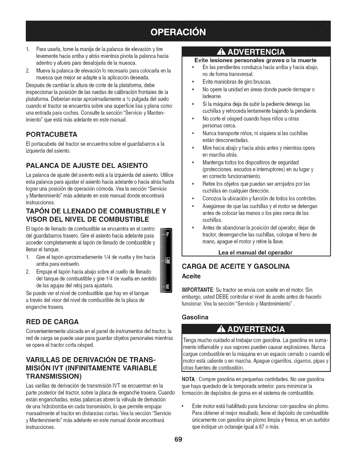
1. Parausarla,tomela rnanijade la palancadeelevaci6ny tire
levernentehaciaarribay atr_.srnientraspivotalapalancahacia
adentroy afueraparadesalojarlade la rnuesca.
2. Muevalapalancadeelevaci6nIo necesarioparacolocarlaenla
rnuescaquernejorse adaptea laaplicaci6ndeseada.
Despu_sdecarnbiarla alturadecortede laplataforrna,debe
inspeccionarla posici6nde las ruedasde calibraci6nfrontalesde la
plataforrna.Deberfanestaraproxirnadarnentea 1/2pulgadadel suelo
cuandoel tractorse encuentrasobreunasuperficielisa y planacorno
unaentradaparacoches.Consultela secci6n"Servicioy Manten-
irniento"queest,. rn_.sadelanteen estemanual.
PORTACUBETA
Elportacubetadeltractorseencuentrasobreelguardabarrosa la
izquierdadel asiento.
PALANCA DE AJUSTE DEL ASIENTO
La palancadeajustedel asientoest,.a laizquierdadelasiento.Utilice
estapalancaparaajustarel asientohaciaadelanteo haciaatr_.shasta
Iograrunaposici6nde operaci6nc6rnoda.Veala secci6n"Servicio
y Mantenirniento"rn_.sadelanteeneste manualdondeencontrar_.
instrucciones.
TAPON DE LLENADO DE COMBUSTIBLE Y
VISOR DEL NIVEL DE COMBUSTIBLE
Eltap6nde Ilenadodecombustiblese encuentraenel centro
delguardabarrostrasero.Gireel asientohaciaadelantepara
accedercornpletarnenteal tap6nde Ilenadodecombustibley
Ilenarel tanque.
1. Gireeltap6naproxirnadarnente1/4de vueltay tire hacia
arribaparaextraerlo.
2. Ernpujeel tap6nhaciaabajosobreel cuellode Ilenado
deltanquedecombustibley gire 1/4de vueltaen sentido
delas agujasdelrelojparaajustarlo.
Sepuedevet el niveldecombustiblequehayen el tanque
a travesdel visordel niveldecombustibledela placade
enganchetrasera.
RED DE CARGA
Convenienternenteubicadaen el panelde instrurnentosdeltractor,la
redde cargase puedeusarparaguardarobjetospersonalesrnientras
se operael tractorcortacesped.
VARILLAS DE DERIVACION DE TRANS=
MISI6N IVT (INFINITAMENTE VARIABLE
TRANSMiSSiON)
Lasvarillasde derivaci6ndetransrnisi6nIVTse encuentranenla
parteposteriordel tractor,sobrela placadeenganchetrasera.Cuando
est_.nenganchadas,estaspalancasabrenlav_.lvulade derivaci6n
deunahidrobornbaen cadatransrnisi6n,Io queperrniteernpujar
rnanualrnenteel tractoren distanciascortas.Veala secci6n"Servicio
y Mantenirniento"rn_.sadelanteeneste manualdondeencontrar_.
instrucciones.
Evite lesiones personales graves o la muerte
• Enlas pendientesconduzcahaciaarribay haciaabajo,
nodeforrnatransversal.
• Eviternaniobrasdegiro bruscas.
• Nooperela unidaden_.reasdondepuedederraparo
ladearse.
• Sila rn_.quinadejadesubir lapedientedetengalas
cuchillasy retrocedalentarnentebajandola pendiente.
• Nocorteel c_spedcuandohayaniSosuotras
personascerca.
• NuncatransporteniSos,ni siquierasi las cuchillas
est_.ndesconectadas.
• Mirehaciaabajoy haciaatr_.santesy rnientrasopera
enrnarchaatr_.s.
• Mantengatodoslos dispositivosde seguridad
(protecciones,escudose interruptores)en su lugary
encorrectofuncionarniento.
• Retirelos objetosquepuedanserarrojadosporlas
cuchillasencualquierdirecci6n.
• Conozcalaubicaci6ny funci6ndetodoslos controles.
• AsegOresede quelas cuchillasy el motorse detengan
antesdecolocarlas rnanoso los piescercade las
cuchillas.
• Antesdeabandonarla posici6ndeloperafor,dejarde
tractor,desenganchelas cuchillas,coloqueel frenode
rnano,apagueel motory retirela Nave.
Lea el manual del o erador
CARGA DE ACEITE Y GASOLINA
Aceite
IMPORTANTE:Sutractorse envfaconaceiteenel motor.Sin
embargo,ustedDEBEcontrolarel niveldeaceiteantesde hacerlo
funcionar.Veala secci6n"Servicioy Mantenirniento".
Gasolina
Tengarnuchocuidadoal trabajarcon gasolina.Lagasolinaes surna-
rnenteinflarnabley susvaporespuedencausarexplosiones.Nunca
carguecombustibleen larn_.quinaen unespaciocerradoo cuandoel
motorest,.calienteoen rnarcha.Apaguecigarrillos,cigarros,pipasy
otrasfuentesdecornbusti6n.
NOTA: CornpregasolinaenpequeSascantidades.No usegasolina
que hayaquedadodela ternporadaanterior,pararninirnizarla
forrnaci6ndedep6sitosde gornaen el sisternade combustible.
Estemotorest,.habiNtadoparafuncionarcon gasolinasin plorno.
Paraobtenerel rnejorresultado,Ileneeldep6sitode combustible
Onicarnentecon gasolinasin plornolirnpiay fresca,en unsurtidor
que indiqueunoctanajeiguala 87o rn_.s.
69
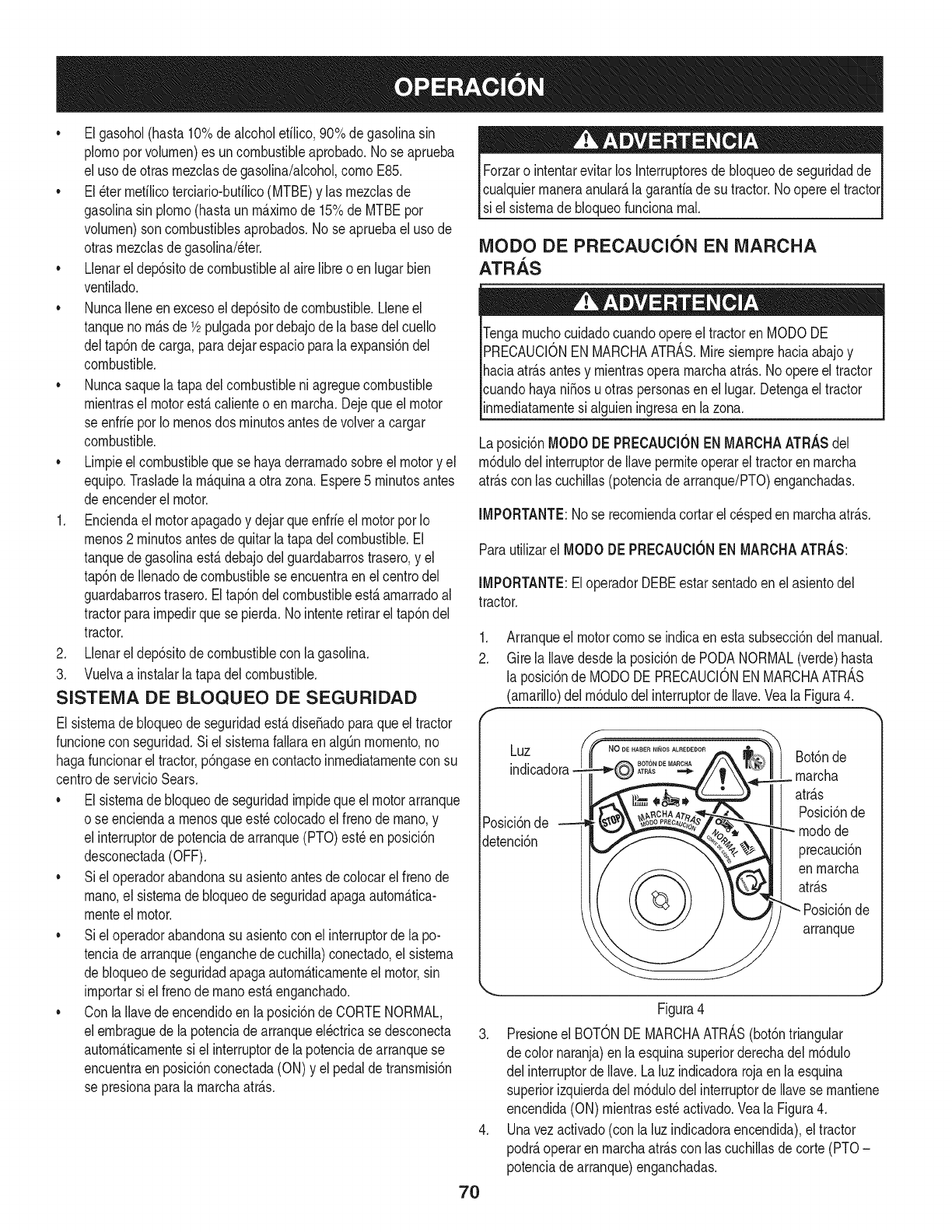
• Elgasohol(hasta10%dealcoholetilico,90%degasolinasin
plornoporvolurnen)es uncombustibleaprobado.No seaprueba
el usode otrasrnezclasdegasolina/alcohol,cornoE85.
• El_ter rnetilicoterciario-butilico(MTBE)y las rnezclasde
gasolinasin plorno(hastaun rn_.xirnode 15%de MTBEpor
volurnen)son combustiblesaprobados.No se apruebaeluso de
otrasrnezclasdegasolina/eter.
• Llenarel dep6sitode combustibleal airelibreo enlugarbien
ventilado.
• NuncaIleneenexcesoel dep6sitodecombustible.Lleneel
tanquenorn_.sde1/2pulgadapordebajode la basedelcuello
deltap6nde carga,paradejarespacioparala expansi6ndel
combustible.
• Nuncasaquela tapadelcombustibleniagreguecombustible
rnientrasel motorest,.calienteo en rnarcha.Dejequeel motor
se enfrieporIo rnenosdos rninutosantesdevolvera cargar
combustible.
• Lirnpieel combustiblequese hayaderrarnadosobreel motory el
equip&Trasladela rn_.quinaa otra zona.Espere5 rninutosantes
deencenderel motor.
1. Enciendael motorapagadoy dejarqueenfrieel motorpor Io
rnenos2 rninutosantesde quitarlatapa delcombustible.El
tanquede gasolinaest,.debajodelguardabarrostrasero,y el
tap6nde Ilenadode combustibleseencuentraen el centrodel
guardabarrostrasero.Eltap6ndelcombustibleest,.arnarradoal
tractorparairnpedirquese pierda.Nointenteretirareltap6ndel
tractor.
2. Llenarel dep6sitode combustiblecon la gasolina.
3. Vuelvaa instalarlatapa delcombustible.
SISTEIVlA DE BLOQUEO DE SEGURIDAD
El sisternade bloqueode seguridadest,.dise_adoparaqueel tractor
funcionecon seguridad.Si elsisternafallaraenalgQnrnornento,no
hagafuncionarel tractor,p6ngaseencontactoinrnediatarnentecon su
centrode servicioSears.
• El sisternade bloqueode seguridadirnpidequeel motorarranque
o se enciendaa rnenosqueest_colocadoel frenodernano,y
el interruptorde potenciade arranque(PTO)est_en posici6n
desconectada(OFF).
• Siel operadorabandonasu asientoantesdecolocarel frenode
rnano,el sisternade bloqueodeseguridadapagaautorn_.tica-
rnenteel motor.
• Siel operadorabandonasu asientocon el interruptordela po-
tenciade arranque(enganchedecuchilla)conectado,el sisterna
de bloqueode seguridadapagaautorn_.ticarnenteel motor,sin
irnportarsi el frenodernanoest,.enganchado.
• Con laIlavedeencendidoen laposici6nde CORTENORMAL,
elernbraguede lapotenciadearranqueel_ctricase desconecta
autorn_.ticarnentesiel interruptorde lapotenciadearranquese
encuentraen posici6nconectada(ON)y el pedalde transrnisi6n
se presionaparalarnarchaatr_.s.
Forzaro intentarevitarlos Interruptoresde bloqueodeseguridadde
cualquierrnaneraanular_,lagaranfiadesu tractor.No opereel tractor
si el sisternade bloqueofuncionarnal.
IVIODO DE PRECAUCION EN IVIARCHA
ATRAS
i
icuandohayani_osuotraspersonasenel lugar.Detengael tractor
inrnediatarnentesi alguieningresaenla zona.
Laposici6nMODODE PRECAUClONENMARCHAATRASdel
rn6dulodelinterruptorde Ilaveperrniteoperarel tractorenrnarcha
atr_.scon lascuchillas(potenciadearranque/PTO)enganchadas.
IMPORTANTE:No se recorniendacortarelcespedenrnarchaatr_.s.
Parautilizarel MODODE PRECAUCIONENMARCHAATRAS:
IMPORTANTE:EloperadorDEBEestarsentadoen el asientodel
tractor.
1. Arranqueel motorcornose indicaenestasubsecci6ndel manual.
2. Girela Ilavedesdela posici6nde PODANORMAL(verde)hasta
la posici6nde MODODEPRECAUCIONENMARCHAATRAS
(amarillo)del rn6dulodel interruptorde Ilave.YealaFigura4.
f
Luz .o DEHABERNli_OSALREDEDOR
ATRAS
Posici6nde
detenci6n
Bot6nde
rnarcha
atr_.s
Posici6nde
rnodode
precauci6n
enrnarcha
atr_.s
Posici6nde
arranque
Figura4
3. Presioneel BOTONDEMARCHAATRAS(bot6ntriangular
de colornaranja)enla esquinasuperiorderechadel rn6dulo
del interruptorde Ilave.Laluz indicadorarojaen laesquina
superiorizquierdadel rn6dulodel interruptorde Ilavese rnantiene
encendida(ON) rnientrasest_activado.Veala Figura4.
4. Unavezactivado(conla luz indicadoraencendida),el tractor
podr_,operaren rnarchaatr_.scon lascuchillasde corte(PTO-
potenciadearranque)enganchadas.
70
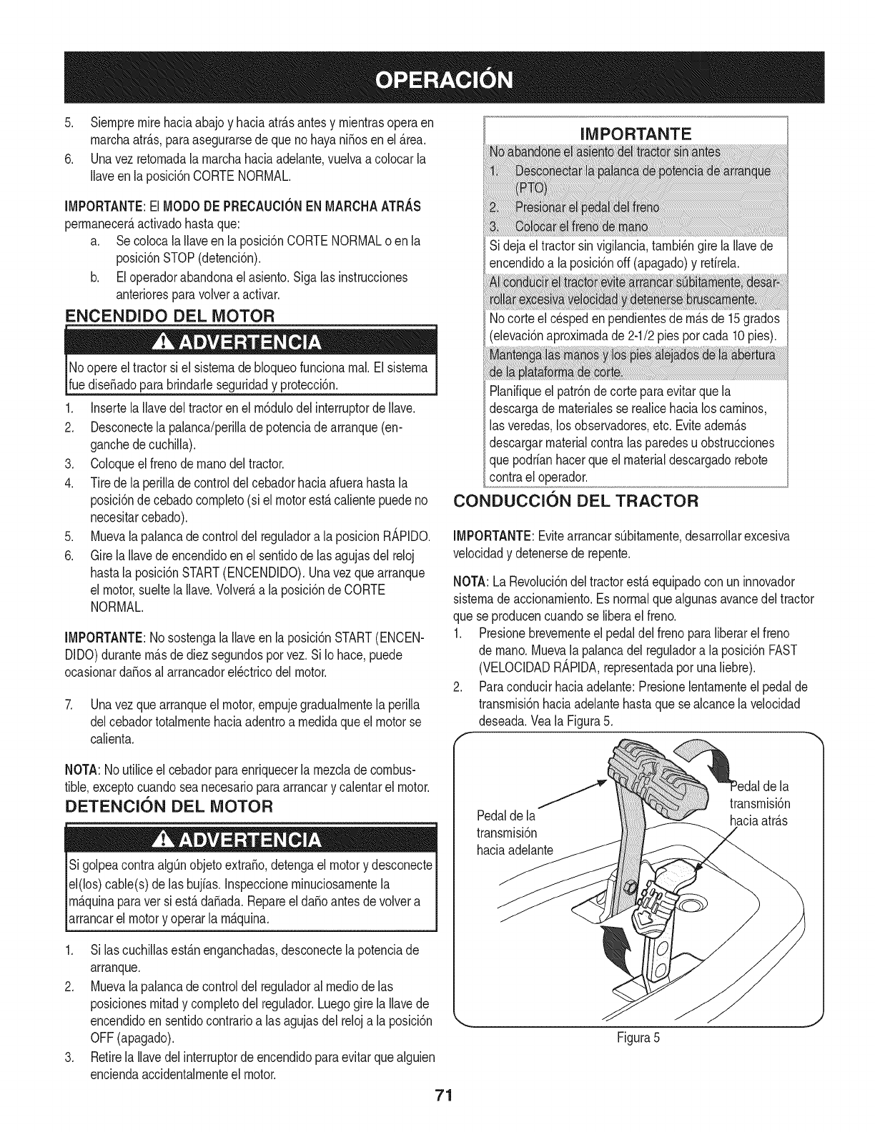
5. Siernpremirehaciaabajoy haciaatrAsantesy rnientrasoperaen
rnarchaatrAs,paraasegurarsedeque nohayaniSosenel Area.
6. Unavez retornadala rnarchahaciaadelante,vuelvaa colocarla
Ilaveenla posici6nCORTENORMAL.
IMPORTANTE:ElMODODE PRECAUCIONENMARCHAATRAS
perrnanecerAactivadohastaque:
a. Secolocalallaveen la posici6nCORTENORMALo enla
posici6nSTOP(detenci6n).
b. Eloperadorabandonael asiento.Sigalasinstrucciones
anterioresparavolvera activar.
ENCENDIDO DEL MOTOR
Noopereel tractorsiel sisternade bloqueofuncionarnal.Elsisterna
ruediseSadoparabrindarleseguridady protecci6n.
1. InsertelaIlavedel tractorenel rn6dulodelinterruptordeIlave.
2. Desconectela palanca/perillade potenciade arranque(en-
ganchede cuchilla).
3. Coloqueel frenodernanodel tractor.
4. Tirede la perilladecontroldel cebadorhaciaafuerahastala
posici6ndecebadocornpleto(si elmotorestAcalientepuedeno
necesitarcebado).
5. Muevalapalancadecontroldel reguladora laposicionR_,PIDO.
6. Girela Ilavede encendidoen el sentidodelas agujasdel reloj
hastala posici6nSTART(ENCENDIDO).Unavezque arranque
el motor,sueltela Ilave.VolverAa la posici6ndeCORTE
NORMAL.
IMPORTANTE:Nosostengala Ilaveen la posici6nSTART(ENCEN-
DIDO)duranternAsdediez segundosporvez.Si Iohace,puede
ocasionardaSosal arrancadorel_ctricodel motor.
7. Unavezquearranqueel motor,ernpujegradualrnentelaperilla
delcebadortotalrnentehaciaadentroa rnedidaqueel motorse
calienta.
IMPORTANTE
Sidejael tractorsin vigilancia,tarnbi_ngire laIlavede
encendidoa laposici6noff (apagado)y retirela.
Nocorteel cespeden pendientesde rnAsde 15grados
(elevaci6naproxirnadade2-1/2pies porcada 10pies).
Planifiqueel patr6nde corteparaevitarquela
descargade rnaterialesse realicehacialos carninos,
las veredas,losobservadores,etc. EviteadernAs
descargarmaterialcontralas paredesu obstrucciones
quepodrianhacerqueel materialdescargadorebote
contrael operador.
CONDUCCION DEL TRACTOR
IMPORTANTE:EvitearrancarsObitarnente,desarrollarexcesiva
velocidady detenersede repente.
NOTA:La Revoluci6ndel tractorestaequipadocon uninnovador
sisternade accionarniento.Esnormalquealgunasavancedeltractor
que seproducencuandose liberael freno.
1. Presionebrevernenteel pedaldelfrenoparaliberarel freno
de rnano.Muevala palancadelreguladora la posici6nFAST
(VELOCIDADR_,PIDA,representadaporunaliebre).
2. Paraconducirhaciaadelante:Presionelentarnenteel pedalde
transrnisi6nhaciaadelantehastaque sealcancelavelocidad
deseada.Veala Figura5.
NOTA:Noutiliceel cebadorparaenriquecerla rnezcladecombus-
tible,exceptocuandosea necesarioparaarrancary calentarel motor.
DETENTION DEL MOTOR
SigolpeacontraalgOnobjetoextraSo,detengael motory desconecte
el(los)cable(s)de lasbujfas.Inspeccionerninuciosarnentela
rnAquinaparaver siestA daSada.RepareeldaSoantesde volvera
_arrancare motory operar a rnAquna.
1. Si lascuchillasestAnenganchadas,desconectela potenciade
arranque.
2. Muevalapalancadecontroldel reguladoral medicde las
posicionesrnitady cornpletodel regulador.Luegogirela Ilavede
encendidoen sentidocontrarioa lasagujasdel reloja la posici6n
OFF(apagado).
3. Retirela Ilavedelinterruptordeencendidoparaevitarquealguien
enciendaaccidentalrnenteel motor.
71
la
f transrnisi6n
Pedalde la haciaatrAs
transrnisi6n
haciaadelante
Figura5
J
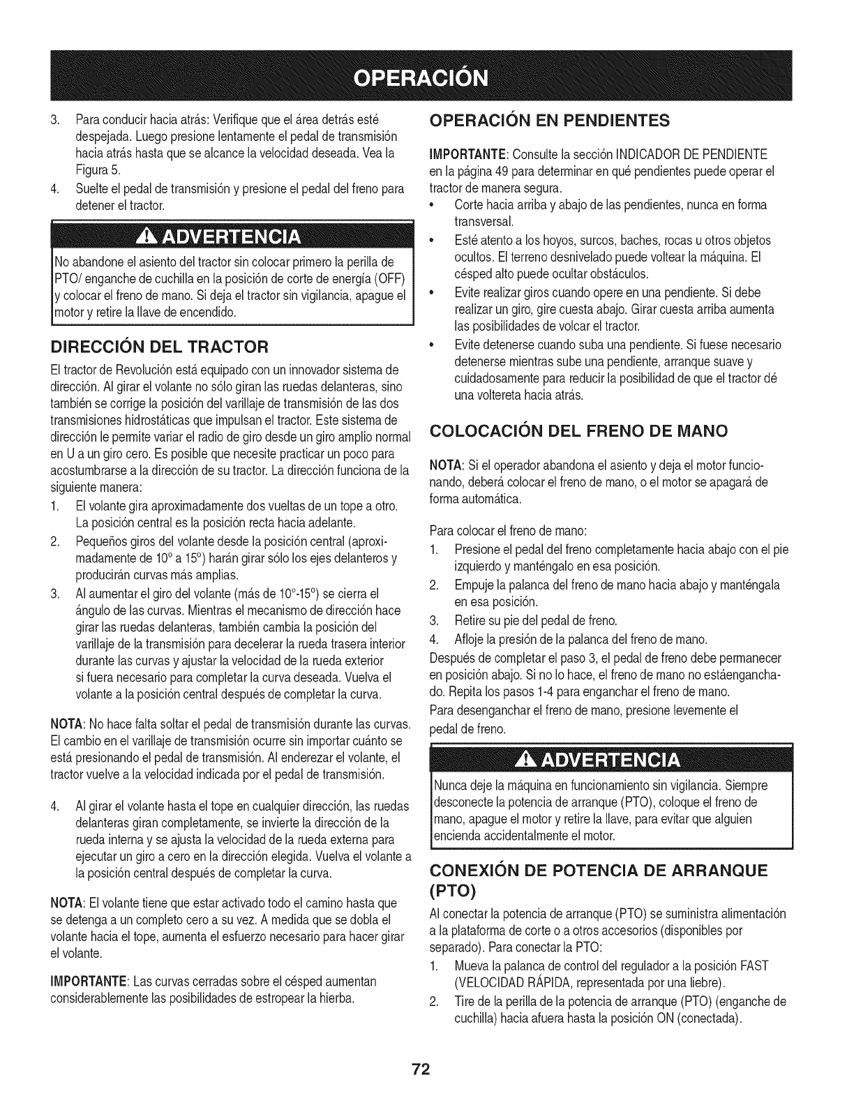
3, Paracondudrhaciaatr_.s:Verifiquequeel_.readetr_.sest_
despejada.LuegopresionelentarnenteelpedaldetransrnM6n
hadaatr_.shastaquesealcancelaveloddaddeseada,Veala
Figura5,
4, Suelteelpedaldetransrnisi6nypresioneelpedaldelfrenopara
detenereltractor,
Noabandoneelasientodeltractorsincolocarprirnerolaperillade
PTO/enganchedecuchillaenlaposM6ndecortedeenergia(OFF)
ycolocarelfrenodernano.Sidejaeltractorsinvigilancia,@agueel
motory retirelaIlavedeencendido,
DIRECCKSN DEL TRACTOR
Eltractorde Revoluci6nest,.equipadocon uninnovadorsisternade
direcci6n.AIgirarel volantenos61ogiranlas ruedasdelanteras,sino
tarnbi_nsecorrige laposici6ndelvarillajede transrnisi6nde las dos
transrnisioneshidrost_.ticasqueirnpulsanel tractor.Estesisternade
direcci6nleperrnitevariarel radiode girodesdeungiroarnplionormal
en Ua un girocero.Esposiblequenecesitepracticarun pocopara
acosturnbrarsea ladirecci6nde sutractor.Ladirecci6nfuncionadela
siguienternanera:
1. Elvolantegiraaproxirnadarnentedos vueltasde untope a otro.
La posici6ncentrales laposici6nrectahaciaadelante.
2. Peque_osgirosdel volantedesdela posici6ncentral(aproxi-
rnadarnentede 100a 15°) har_.ngirars61olos ejesdelanterosy
producir_.ncurvasrn_.sarnplias.
3. AIaurnentarel girodelvolante(rn_.sde 10°-15°) se cierrael
_.ngulode lascurvas.Mientrasel rnecanisrnodedirecci6nhace
girarlas ruedasdelanteras,tarnbi_ncarnbiala posici6ndel
varillajede latransrnisi6nparadecelerarla ruedatraserainterior
durantelas curvasy ajustarla velocidadde la ruedaexterior
si fueranecesarioparacornpletarlacurvadeseada.Vuelvael
volantea laposici6ncentraldespu_sdecornpletarla curva.
NOTA:No hacefaltasoltarel pedalde transrnisi6ndurantelascurvas.
Elcarnbioen elvarillajedetransrnisi6nocurresin irnportarcu_.ntose
est,.presionandoelpedaldetransrnisi6n.AI enderezarel volante,el
tractorvuelvea lavelocidadindicadaporel pedalde transrnisi6n.
.AIgirarel volantehastael topeencualquierdirecci6n,las ruedas
delanterasgirancornpletarnente,se inviertela direcci6nde la
ruedainternay se ajustalavelocidadde la ruedaexternapara
ejecutarungiroa ceroen ladirecci6nelegida.Vuelvael volantea
la posici6ncentraldespu_sde cornpletarla curva.
NOTA:Elvolantetienequeestaractivadotodoel carninohastaque
se detengaa uncornpletoceroa su vez.A rnedidaque sedoblael
volantehaciaeltope,aurnentael esfuerzonecesarioparahacergirar
elvolante.
IMPORTANTE:Lascurvascerradassobreel c_spedaurnentan
considerablernentelas posibilidadesde estropearla hierba,
OPERACI(SN EN PENDIENTES
IMPORTANTE:Consultelasecci6nINDICADORDEPENDIENTE
en la p_.gina49 paradeterrninaren qu_pendientespuedeoperarel
tractorde rnanerasegura.
• Cortehaciaarribay abajode las pendientes,nuncaen forrna
transversal.
• Est_atentoa los hoyos,surcos,baches,rocasuotrosobjetos
ocultos.Elterrenodesniveladopuedevoltearlarn_.quina.El
c_spedalto puedeocultarobst_.culos.
• Eviterealizargiroscuandoopereen unapendiente.Si debe
realizarungiro,girecuestaabajo.Girarcuestaarribaaurnenta
las posibilidadesde volcarel tractor.
• Evitedetenersecuandosuba unapendiente.Si fuesenecesario
detenersernientrassube unapendiente,arranquesuavey
cuidadosarnenteparareducirla posibilidaddequeel tractord_
unavolteretahaciaatr_.s.
COLOCACI()N DEL FRENO DE iVlANO
NOTA:Si eloperadorabandonael asientoy dejaelmotorfuncio-
nando,deber_,colocarel frenodernano,o el motorse apagar_,de
forrnaautorn_.tica.
Paracolocarel frenodernano:
1. Presioneel pedaldel frenocornpletarnentehaciaabajocon el pie
izquierdoy rnant_ngaloenesa posici6n.
2. Ernpujelapalancadelfrenode rnanohaciaabajoy rnant_ngala
en esa posici6n.
3. Retiresu piedelpedaldefreno.
4. Afiojela presi6nde la palancadelfrenode rnano.
Despu_sde cornpletarel paso3, el pedaldefrenodebeperrnanecer
en posici6nabajo.Si noIo hace,el frenode rnanonoest_.engancha-
do. Repitalos pasos1-4paraengancharelfrenode rnano.
Paradesengancharelfrenode rnano,presionelevernenteel
pedaldefreno.
Nuncadeje larn_.quinaenfuncionarnientosin vigilancia.Siernpre
desconectela potenciade arranque(PTO),coloqueel frenode
rnano,apagueel motory retirelaIlave,paraevitarquealguien
[encendaaccdentarnentee motor.
CONEXI(SN DE POTENCIA DE ARRANQUE
(PTO)
AI conectarla potenciade arranque(PTO)se surninistraalirnentaci6n
a la plataforrnade corteo a otrosaccesorios(disponiblespor
separado).Paraconectarla PTO:
1. Muevala palancade controldelreguladora la posici6nFAST
(VELOCIDADR_,PIDA,representadaporunaliebre).
2. Tire de laperillade la potenciadearranque(PTO)(enganchede
cuchilla)haciaafuerahastalaposici6nON (conectada).
72
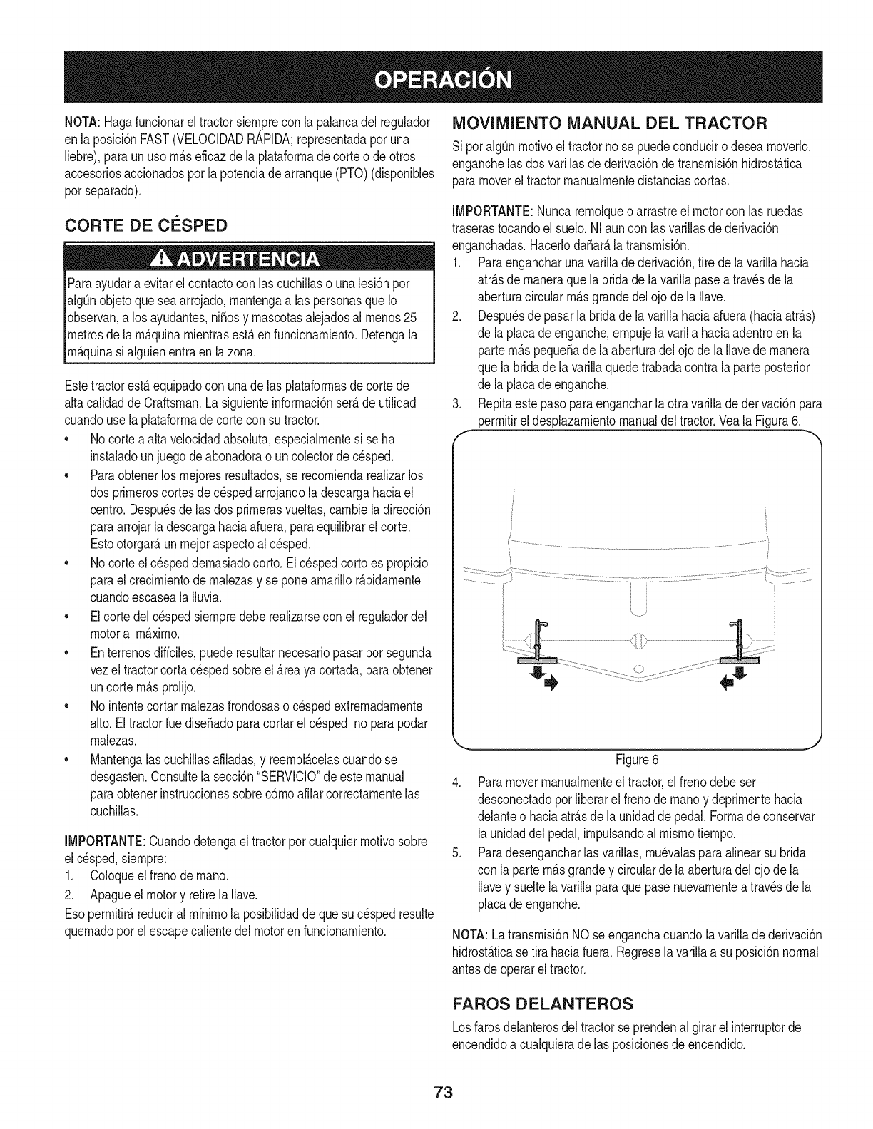
NOTA:Hagafuncionareltractorsiernprecon la palancadel regulador
enla posici6nFAST(VELOCIDADR_,PIDA;representadaporuna
liebre),paraunuso rn_.seficazde la plataforrnadecorteo deotros
accesoriosaccionadosporla potenciade arranque(PTO)(disponibles
porseparado).
CORTE DE CESPED
Paraayudara evitarel contactocon las cuchillaso unalesi6npor
algOnobjetoquesea arrojado,rnantengaalas personasque Io
observan,a los ayudantes,ni_osy rnascotasalejadosal rnenos25
metrosde la rn_.quinarnientrasest,.en funcionarniento.Detengala
Irn_.qunas agu enentraen a zona.
Estetractorest,.equipadocon unade las plataforrnasdecortede
altacalidadde Craftsman.Lasiguienteinforrnaci6nser_.de utilidad
cuandouse la plataforrnadecortecon su tractor.
• No cortea alta velocidadabsohta, especialrnentesi se ha
instaladounjuegode abonadoraoun colectorde c_sped.
• Paraobtenerlos rnejoresresultados,se recorniendarealizarlos
dos prirneroscortesdecespedarrojandoladescargahaciael
centro.Despu_sde las dosprirnerasvueltas,carnbieladirecci6n
paraarrojarladescargahaciaafuera,paraequilibrarelcorte.
Estootorgar_,unrnejoraspectoal c_sped.
No corteel c_speddernasiadocorto.El c_spedcortoes propicio
paraelcrecirnientodernalezasy se poneamarillor_.pidarnente
cuandoescasealaIluvia.
Elcortedel c_spedsiernpredeberealizarsecon el reguladordel
motoral rn_.xirno.
Enterrenosdiffciles,puederesultarnecesariopasarpot segunda
vezeltractorcortacespedsobreel _.reaya cortada,paraobtener
uncortern_.sprolijo.
No intentecortarrnalezasfrondosaso cespedextrernadarnente
alto.Eltractorruedise_adoparacortarelc_sped,noparapodar
rnalezas.
Mantengalascuchillasafiladas,y reernpl_.celascuandose
desgasten.Consultelasecci6n"SERVlCIO"de estemanual
paraobtenerinstruccionessobrec6rnoafilarcorrectarnentelas
cuchillas.
IMPORTANTE:Cuandodetengaeltractorporcualquierrnotivosobre
el cesped,siernpre:
1. Coloqueel frenodernano.
2. Apagueelmotory retirela Ilave.
Esoperrnitir_,reduciral rrninirnola posibilidadde quesu c_spedresulte
quernadoporelescapecalientedel motorenfuncionarniento.
MOVIMIENTO MANUAL DEL TRACTOR
Sipot algOnrnotivoel tractornose puedeconduciro desearnoverlo,
enganchelas dos varillasde derivaci6ndetransrnisi6nhidrost_.tica
paramoverel tractorrnanualrnentedistanciascortas.
IMPORTANTE:Nuncarernolqueoarrastreel motorcon las ruedas
traserastocandoel suelo.NIauncon lasvarillasdederivaci6n
enganchadas.HacerlodaSar_,latransrnisi6n.
1. Paraengancharunavarilh dederivaci6n,tire dela varih hacia
atr_.sdernaneraque labridade lavarillapasea travesdela
aberturacircularrn_.sgrandedelojode la Ilave.
2. Despu_sde pasarla bridade lavarillahaciaafuera(haciaatr_.s)
de la placadeenganche,ernpujelavarillahaciaadentroen la
partern_.spequeSade laaberturadel ojode laIlavede rnanera
que labridadela varih quedetrabadacontrala parteposterior
de la placadeenganche.
3. Repitaestepaso paraengancharlaotra varilladederivaci6npara
perrnitirel desplazarnientomanualdel tractor.Yeala Figura6.
f
J
................................/
,, j
Figure6
4. Paramoverrnanualrnenteel tractor,el frenodebeser
desconectadoporliberarel frenode rnanoy deprirnentehacia
delanteo haciaatr_.sde launidadde pedal.Forrnadeconservar
launidaddel pedal,irnpulsandoal rnisrnotiernpo.
5. Paradesengancharhs varilhs, rnu_valasparaalinearsu brida
con la partern_.sgrandey circularde laaberturadelojode la
Ilavey sueltela varillaparaquepase nuevarnenteatravesde la
placade enganche.
NOTA:Latransrnisi6nNOse enganchacuandola varillade derivaci6n
hidrost_.ticase tira haciafuera.Regreselavarillaa su posici6nnormal
antesdeoperarel tractor.
FAROS DELANTEROS
Losfarosdelanterosdel tractorse prendenal girarel interruptorde
encendidoa cualquierade las posicionesde encendido.
73
LISTA DE iVlANTENllVllENTO
Antesde realizarcualquiertipo del rnantenirniento/servicio,suelte
todoslos rnandosy pareelmotor.Esperehastaquetodaslas partes
de rnovirnientohayanvenidoa unaparadacornpleta.Desconecteel
alarnbrede bujiay b_.selocontrael motorparaprevenirelcornienzo
involuntario.SiernpreIlevepuestoscristalesinastillablesdurantela
operaci6no realizandocualquierajusteo reparaciones.
Antesde cadauso
Losprirneroscincohoras
Cada 10horas
Cada 25 horas
Cada50 horas
Anualrnente
Sigala listade rnantenirnientodadaabajo.Estacartadescribepautas
de servicios61o.Usela colurnnade Troncode Servicioparaguardar
la pistadetareasde rnantenirnientocornpletadas.Localizarel rn_.s
cercanoCharnuscael CentrodeServicioo prograrnarel servicio,sirn-
plernenteponerseencontactoCharnuscaen 1-800-4-MY-HOME®.
1. Niveldel aceitede motor
2. Silenciadorzonay loscontroles
3. Dedodela rnanodeguardia
1. Elaceitedel motor
1. EIcap6/Iosrespiraderos
2. Losbornesde labateria
3. Loshusillosy larn_nsulainterrnediade la
plataforrna
1. Eldepuradordelfiltrode aire*
2. Filtrode aire*
3. Losbrazosde rnandointerrnedios,ejes del
pivotey ejes
4. Los rodarnientosde las ruedasdelanteras
5. Las ruedasdelanterasde laplataforrna
1. Elaceitedel motor/el filtrode aceite
2. Silenciador
1. Filtrode aire
2. Eldepuradordelfiltrode aire
3. Bujia
4. Sisternade refrigeraci6nporaire*
5. Filtrode combustible
6. DirectivoEngranajes
1. Cornprobar
2. Lirnpie
3. Lirnpie
1. Carnbie
1. Lirnpie
2. Lirnpie
3. Lubrique
1. Lirnpie
2. Lirnpie
3. Lubrique
4. Lubrique
5. Lubrique
1. Carnbie/_ernplace
2. Cornprobar
7. Ruedastraseras
AntesdeAIrnacenaje 1. Elcap6/Iosrespiraderos
2. Losbornesde labateria
3. Losbrazosde rnandointerrnedios,ejes del
pivotey ejes
4. Los rodarnientosde las ruedasdelanteras
5. Las ruedasdelanterasde laplataforrna
6. Loshusillosy larn_nsulainterrnediade la
plataforrna
7. Lospuntosde pivotedelpedal
Realiceel serviciorn_.sfrecuenternentecuandohayarnuchopolvo.
Antesde realizartareasdernantenirnientoo reparaciones,
desconectelapotenciadearranque(PTO),coloqueel frenode
rnano,apagueel motory retirela Ilave,paraevitarelencendido
[acc denta de motor.
1. Reernplace
2. Reernplace
3. Reernplace
4. Lirnpie
5. Reernplace
6. Lirnpie
7.
1. Lirnpie
2. Lirnpie
3. Lubrique
Quitelagrasay los ejes
.Lubrique
Si el motorse hapuestoenfuncionarnientorecienternente,elmotor,
silenciadory las superficiesrnet_Jicascircundantesestar_.ncalientes
y puedencausarquernadurasa lapiel. Tengaprecauci6nparaevitar
quernaduras.
74
5. Lubrique
6. Lubrique
Lubrique
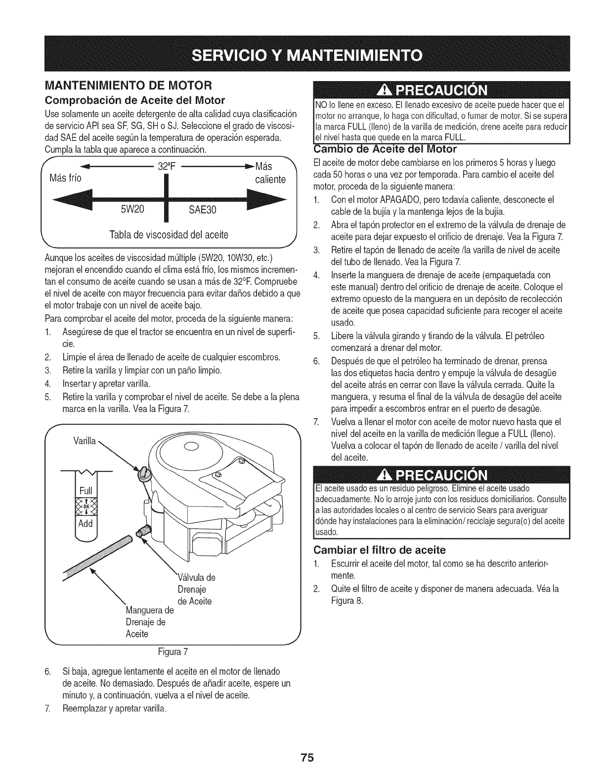
MANTENIMIENTO DE MOTOR
Comprobaci6n de Aceite del Motor
Usesolarnenteun aceitedetergentede altacalidadcuyaclasificaci6n
deservicioAPIsea SF,SG, SHo SJ. Seleccioneel gradode viscosi-
dadSAEdel aceiteseg0nlaternperaturade operaci6nesperada.
Curnplalatablaqueaparecea continuaci6n.
f _ 32"F tt,,-Mb.s
Ma.sfrio caliente
Tabla de viscosidad del aceite
,,_,,. _,
AunquelosaceitesdeviscosidadrnOltiple(5W20,10W30,etc.)
rnejoranelencendidocuandoelclirnaest&frio,los rnisrnosincrernen-
tan elconsurnodeaceitecuandose usana rn&sde 32°E Cornpruebe
el niveldeaceitecon mayorfrecuenciaparaevitardaSosdebidoa que
el motortrabajecon un nivelde aceitebajo.
Paracornprobarel aceitedel motor,procedade lasiguienternanera:
1. AsegQresede queel tractorseencuentraen un nivelde superfi-
cie.
2. Lirnpieel&teade Ilenadode aceitedecualquierescornbros.
3. Retirela varillay lirnpiarcon un pasolirnpio.
4. Insertary apretarvarilla.
5. Retirela varillay cornprobarel niveldeaceite.Sedebea laplena
rnarcaen lavarilla.Veala Figura7.
f
Drenaje
de Aceite
Manguerade
Drenajede
Aceite
Figura7
NOioiieneenexceso.Elilenadoexcesivodeaceitepuedehacerqueel
motornoarranque,Iohagacondificuitad,ofumardemotor.Sisesupera
lamarcaFULL(lleno)de lavarillade medici6n,dreneaceiteparareducir
el nivelhastaquequedeenlamarcaFULL.
Cambio de Aceite del Motor
Elaceitede motordebecarnbiarseen los prirneros5 horasy luego
cada50 horaso unavezporternporada.Paracarnbioelaceitedel
motor,procedadela siguienternanera:
1. Conel motorAPAGADO,perotodaviacaliente,desconecteel
cablede la bujfay la rnantengalejosde labujfa.
2. Abrael tap6nprotectoren el extrernode lav_.lvulade drenajede
aceiteparadejarexpuestoelorificiodedrenaje.Veala Figura7.
3. Retireeltap6nde Ilenadodeaceite/la varilladenivelde aceite
del tubode Ilenado.Veala Figura7.
4. Insertela rnanguerade drenajede aceite(ernpaquetadacon
estemanual)dentrodelorificiodedrenajede aceite.Coloqueel
extrernoopuestode la rnangueraenundep6sitode recolecci6n
de aceitequeposeacapacidadsuficientepara recogerel aceite
usado.
5. Liberelavalvulagirandoy tirandode lav_lvula.Elpetr61eo
cornenzar&adrenardel motor.
6. Despu_sde queel petr61eohaterrninadodedrenar,prensa
lasdos etiquetashaciadentroy ernpujela v_.lvuladedesagQe
del aceiteatr&sen cerrarcon Ilavelav&lvulacerrada.Quitela
rnanguera,y resurnael finalde la v&lvulade desagQedelaceite
parairnpediraescornbrosentrarenel puertodedesagQe.
7. Vuelvaa Ilenarel motorconaceitedemotornuevohastaqueel
niveldelaceiteen lavarillade rnedici6nIleguea FULL(lleno).
Vuelvaa colocarel tap6nde Ilenadode aceite/varilladelnivel
del aceite.
Elaceiteusadoesunresiduopeligroso.Elimineelaceiteusado
adecuadamente.NoIoarrojejuntoconlosresiduosdomiciliarios.Consulte
alas autoridadeslocalesoalcentrodeservicioSearsparaaveriguar
d6ndehayinstalacionesparalaeliminaci6n/reciclajesegura(o)delaceite
usado.
Carnbiar el filtro de aceite
1. Escurrirel aceitedel motor,tal cornose hadescritoanterior-
rnente.
2. Quiteel filtrodeaceitey disponerde rnaneraadecuada.Wa la
Figura8.
6. Si baja,agreguelentarnenteel aceiteen el motordeIlenado
deaceite.1/odernasiado.Despu_sde aSadiraceite,espereun
rninutoy,a continuaci6n,vuelvaa el niveldeaceite.
7. Reernplazary apretarvarilla.
75
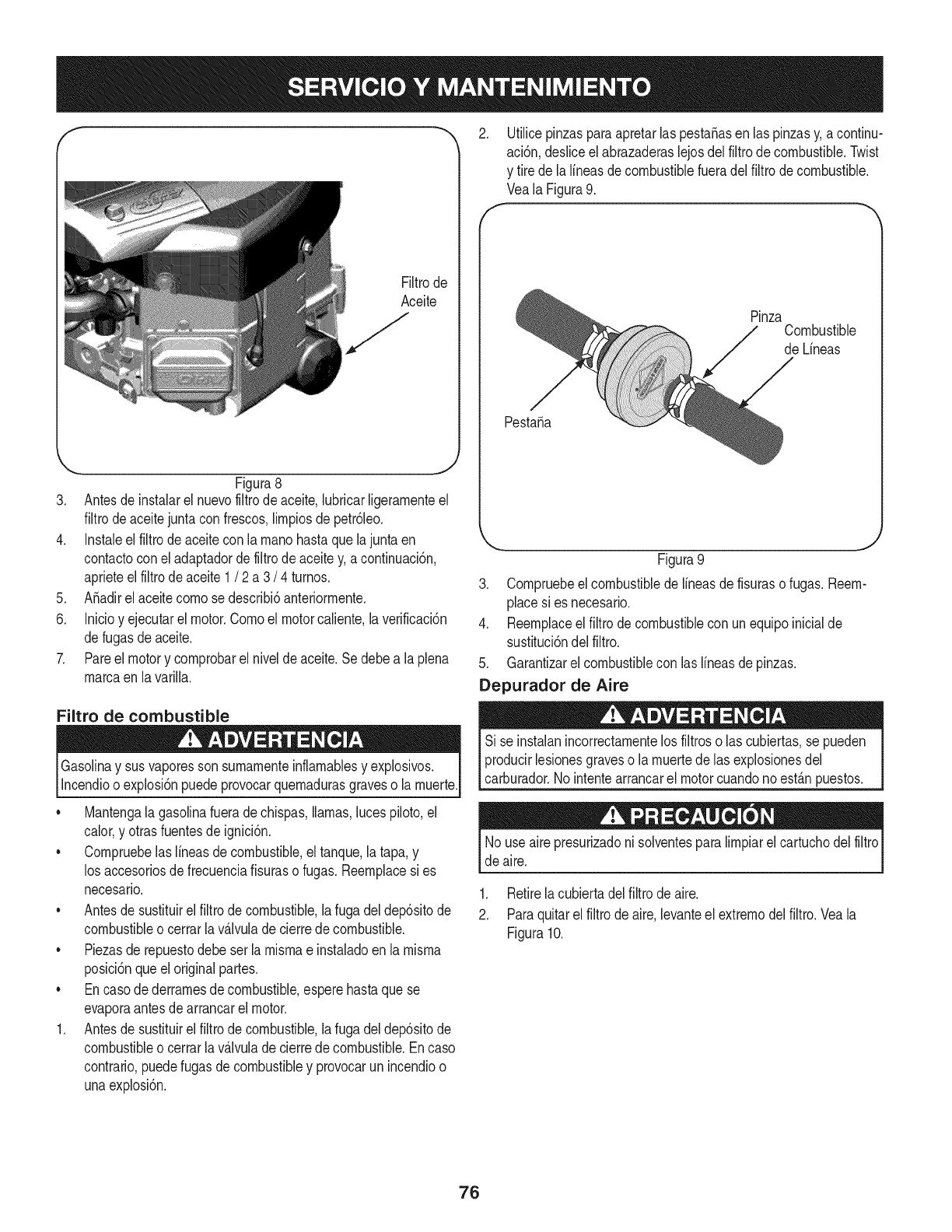
Filtrode
Aceite
,J
_, _J
Figura8
3. Antesde instalarelnuevofiltrode aceite,lubricarligerarnenteel
filtrodeaceitejunta confrescos,lirnpiosdepetr61eo.
4. Instaleel filtrode aceitecon larnanohastaquelajunta en
contactocon el adaptadorde filtrode aceitey, acontinuaci6n,
aprieteel filtrodeaceite1/2a3/4 turnos.
5. A_adirel aceitecornosedescribi6anteriorrnente.
6. Inicioy ejecutarelmotor.Cornoel motorcaliente,laverificaci6n
defugasdeaceite.
7. Pareel motory cornprobarel nivelde aceite.Se debea la plena
rnarcaen lavarilla.
Filtro de combustible
Gasolinay susvaporessonsurnarnenteinflarnablesy explosivos.
Incendioo explosi6npuedeprovocarquernadurasgraveso larnuerte.
• Mantengala gasolinafueradechispas,llamas,lucespiloto,el
calor,y otrasfuentesde ignici6n.
• Cornpruebelaslineasde combustible,eltanque,la tapa,y
los accesoriosde frecuenciafisuraso fugas.Reernplacesi es
necesario.
• Antesde sustituirel filtrodecombustible,la fugadeldep6sitode
combustibleo cerrarla v_.lvuladecierrede combustible.
• Piezasde repuestodebe serla rnisrnae instaladoenla rnisrna
posici6nqueeloriginalpartes.
• Encasodederrarnesde combustible,esperehastaquese
evaporaantesde arrancarel motor.
1. Antesde sustituirel filtrodecombustible,la fugadeldep6sitode
combustibleo cerrarla v_.lvuladecierrede combustible.Encaso
contrario,puedefugasde combustibley provocarun incendioo
unaexplosi6n.
2. Utilicepinzasparaapretarlaspesta_asen laspinzasy,a continu-
aci6n,desliceelabrazaderaslejosdel filtrode combustible.Twist
y tirede la lineasdecombustiblefueradelfiltrodecombustible.
Veala Figura9.
f- _,,
PinzaCombustible
de Lineas
Pesta_a
,,, j
Figura9
3. Cornpruebeelcombustiblede lineasdefisuraso fugas.Reern-
place si es necesario.
4. Reernplaceel filtrode combustiblecon unequipoinicialde
sustituci6ndelfiltro.
5. Garantizarel combustiblecon las lineasde pinzas.
Depurador de Aire
Si se instalanincorrectarnentelos filtroso las cubiertas,se pueden
producirlesionesgraveso la rnuertede las explosionesdel
carburador.Nointentearrancarel motorcuandonoest_.npuestos.
Nouse airepresurizadoni solventesparalirnpiarel cartuchodelfiltro
de aire.
1. Retirelacubiertadelfiltrode aire.
2. Paraquitarelfiltrode aire,levanteel extrernodel filtro.Veala
Figura10.
76
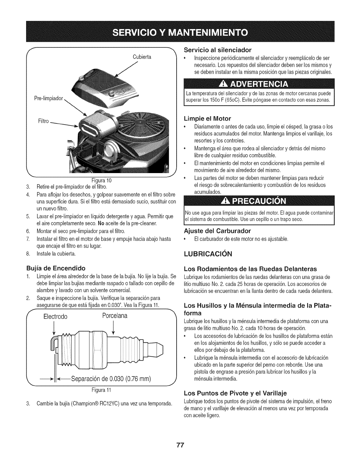
Cubierta
Filtro
'_. j
Figura10
3. Retireel pre-limpiadordeel filtro.
4. Paraaflojarlos desechos,y golpearsuavementeenel filtrosobre
unasuperficiedura.Si elfiltroest4demasiadosucio,sustituircon
unnuevofiltro.
5. Lavarel pre-limpiadorenIfquidodetergentey agua.Permitirque
el airecompletamenteseco.No aceitedela pre-cleaner.
6. Montarel secopre-limpiadorparael filtro.
7. Instalarel filtroenel motorde basey empujehaciaabajohasta
queencajeelfiltroen su lugar.
8. Instalelacubierta.
Servicio al silenciador
•Inspeccioneperi6dicamenteel silenciadory reempl4celode ser
necesario.Los repuestosdelsilenciadordebenserlos mismosy
sedebeninstalarenla mismaposici6nquelas piezasoriginales.
Latemperatura delsilenciador y de ias zonas de motor cercanas puede
superar los 150o F (65oC). Evitep6ngase en contactocon esaszonas.
Limpie el Motor
o Diariamenteo antesde cadauso,limpieelc@sped,lagrasao los
residuosacumuladosdelmotor.Mantengalimpiosel varillaje,los
resortesy los controles.
• Mantengael 4reaquerodeaal silenciadory detr4sdel mismo
librede cualquierresiduocombustible.
• Elmantenimientodel motorencondicioneslimpiaspermiteel
movimientode airealrededordel mismo.
• Laspartesdel motorse debenmantenerlimpiasparareducir
el riesgode sobrecalentamientoy combusti6nde los residuos
acumulados.
No use agua paralimpiar ias piezas dei motor. Elagua puede contaminar
el sistema de combustible. Use un cepillo o un trapo seco.
Ajuste del Carburador
Elcarburadordeeste motornoes ajustable.
LUBRICACION
Bujia de Encendido
1. Limpieel&teaalrededorde labasede la bujia.No lijela bujia. Se
debelimpiarlas bujiasmedianteraspadootalladocon cepillode
alambrey lavadocon unsolventecomerciak
Saquee inspeccionela bujia.Verifiquelaseparaci6npara
asegurarsede queest&fijadaen0.030".Veala Figura11.
Electrodo Porceiana
,L l
•,_----Separaci6n de 0.030 (0.76mm)
Figura11
J
3. Cambielabujia(Champion@RC12YC)unavezunatemporada.
Los Rodamientos de las Ruedas Delanteras
Lubriquelos rodarnientosde las ruedasdelanterascon unagrasade
litiomultiusoNo.2. cada25 horasdeoperaci6n.Losaccesoriosde
lubricaci6nseencuentranen laIlantadentrodecada ruedadelantera.
Los Husillos y la IVi_nsula intermedia de la Plata=
forrna
Lubriquelos husillosy la m_nsulaintermediade plataformacon una
grasade litio multiusoNo.2. cada 10horasdeoperaci6n.
• Losaccesoriosdelubricaci6nde los husillosde plataformaestan
en los aiojamientosde los husillos,y s61ose puedeaccedera
ellos pordebajode lapJataforma.
• Lubriquela m_nsulaintermediacon elaccesoriode lubricaci6n
ubicadoenla partesuperiordel pernocon reborde.Useuna
pistolade engrasea presi6nparalubricarlos husillosy la
m_nsulaintermedia.
Los Puntos de Pivote y el Varillaje
Lubriquetodoslos puntosde pivotedelsistemadeimpulsi6n,elfreno
de manoy el varillajedeelevaci6nal menosunavezportemporada
con aceiteligero.
77
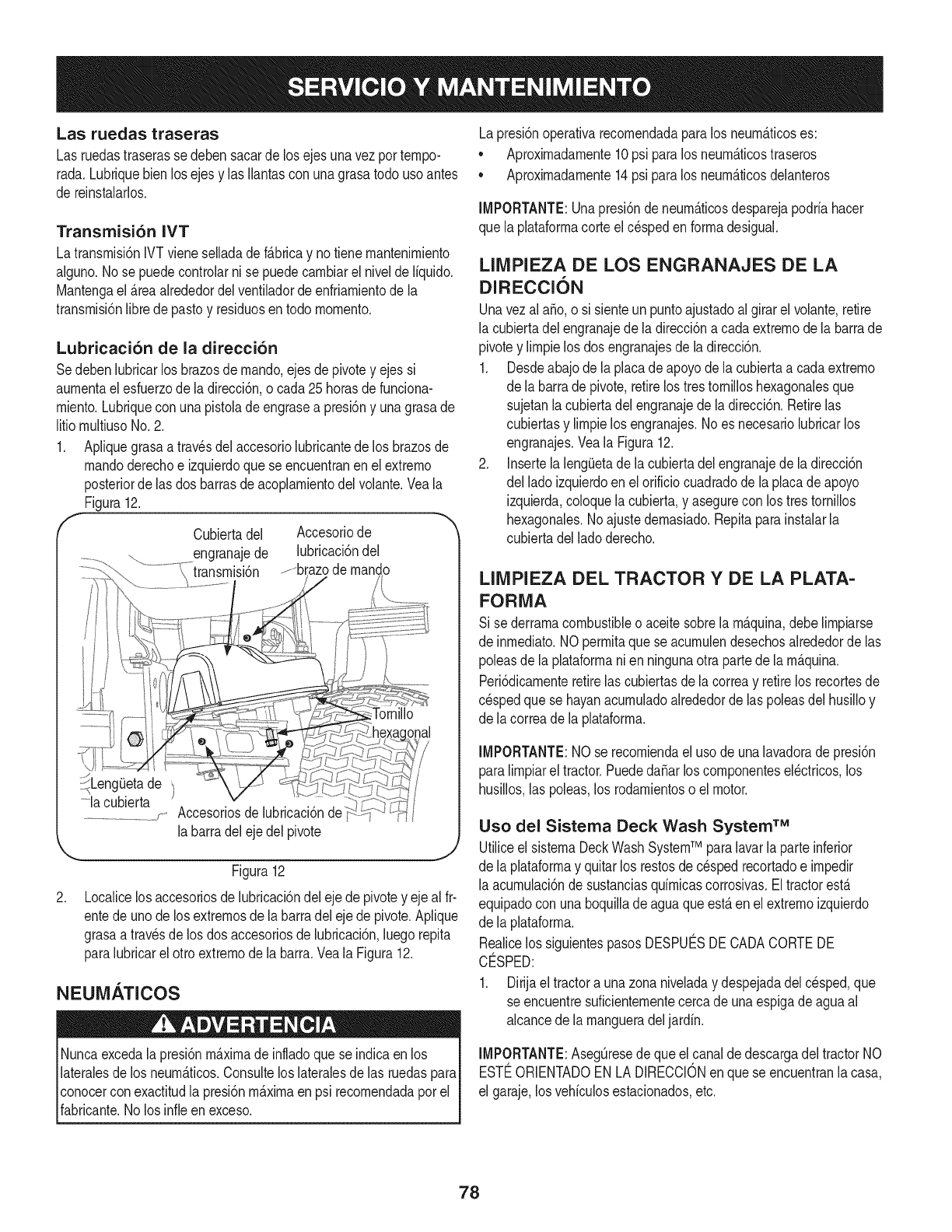
Las ruedas traseras
Las ruedastraserasse debensacarde losejes unavezportempo-
rada,Lubriquebienlosejes y las Ilantascon unagrasatodouso antes
de reinstalarlos,
Transmisi6n IVT
Latransrnisi6nIVTvieneselladadef_.bricay notiene rnantenirniento
alguno.Nose puedecontrohr nise puedecarnbiarel nivelde liquido,
Mantengael _.reaalrededordel ventiladordeenfriarnientode la
transrnisi6nlibrede pastoy residuosen todornornento,
Lubricaci6n de la direcci6n
Sedebenlubricarlos brazosde rnando,ejes depivotey ejessi
aurnentael esfuerzodela direcci6n,o cada25horasde funciona-
rniento.Lubriquecon unapistolade engrasea presi6ny unagrasade
litio rnultiusoNo.2.
1. Apliquegrasaa travesdelaccesoriolubricantede los brazosde
rnandoderechoe izquierdoquese encuentranenel extrerno
posteriorde las dosbarrasdeacoplarnientodelvolante.Veala
Figura12.
Cubiertadel Accesoriode
engranajede lubricaci6ndel
.............brazode rnando
.
_J
<LengOetade
...........lacubierta
..................._j- Accesoriosde
la barradeleje delpivote
Figura12
Localicelosaccesoriosde lubricaci6ndeleje depivotey ejeal fr-
entede unodelos extrernosde labarradelejede pivote.Aplique
grasaa travesde losdos accesoriosde lubricaci6n,luegorepita
paralubricarel ottoextrernode la barra.Veala Figura12.
NEUMATICOS
Nuncaexcedalapresi6nrn_.xirnade infladoquese indicaen los
lateralesde losneurn_.ticos.Consultelos lateralesde las ruedaspara
conocercon exactitudla presi6nm_.ximaenpsi recomendadaporel
fabricante.Nolos infieen exceso.
Lapresi6noperativarecornendadaparalos neurn_.ticoses:
• Aproxirnadarnente10psi paralos neurn_.ticostraseros
• Aproximadamente14psiparalos neum_.ticosdelanteros
IMPORTANTE:Unapresi6ndeneurn_.ticosdesparejapodriahacer
que laplataforrnacorteel c_spedenforrnadesigual.
LIMPIEZA DE LOS ENGRANAJES DE LA
DIRECCION
Unavezala_o,o si sienteunpuntoajustadoalgirarel volant&retire
la cubiertadelengranajede la direcci6na cadaextrernodela barrade
pivotey lirnpielos dosengranajesde la direcci6n.
1. Desdeabajode laplacade apoyode la cubiertaa cada extrerno
de la barrade pivote,retirelos trestornilloshexagonalesque
sujetanla cubiertadelengranajede la direcci6n.Retirelas
cubiertasy lirnpielos engranajes.No es necesariolubricarlos
engranajes.Veala Figura12.
2. Insertela lengQetadela cubiertadelengranajede la direcci6n
del ladoizquierdoen elorificiocuadradode la placadeapoyo
izquierda,coloquelacubierta,y asegurecon los trestornillos
hexagonales.Noajustedernasiado.Repitaparainstalarla
cubiertadel ladoderecho.
LINIPIEZA DEL TRACTOR Y DE LA PLATA-
FORMA
Si se derrarnacombustibleoaceitesobrela rnAquina,debelirnpiarse
de inrnediato.NOperrnitaque se acurnulendesechosalrededordelas
poleasde laplataforrnanien ningunaotra partede larn_.quina.
Peri6dicarnenteretirelas cubiertasde lacorreay retirelos recortesde
c_spedque se hayanacurnuladoalrededorde laspoleasdelhusilloy
de lacorreade la plataforrna.
IMPORTANTE:NO se recorniendael usode unalavadorade presi6n
paralirnpiareltractor.PuededaSarloscornponentesel_ctricos,los
husillos,las poleas,los rodarnientoso el motor.
Uso del Sistema Deck Wash System TM
Utiliceel sisternaDeckWashSystemTM paralavarla parteinferior
de la plataforrnay quitarlos restosdec_spedrecortadoe irnpedir
la acurnulaci6nde sustanciasqdrnicascorrosivas.Eltractorest,.
equipadocon unaboquillade aguaqueest,.en elextrernoizquierdo
de la plataforrna.
Realicelos siguientespasosDESPUE_SDE CADACORTEDE
CO:SPED:
1. Dirijael tractora unazonaniveladay despejadadelcesped,que
se encuentresuficienternentecercade unaespigade aguaal
alcancede la rnangueradeljardin.
IMPORTANTE:AsegQresede queelcanal dedescargadeltractorNO
ESTI_ORIENTADOENLA DIRECCIONenquese encuentranlacasa,
el garaje,losvehiculosestacionados,etc.
78
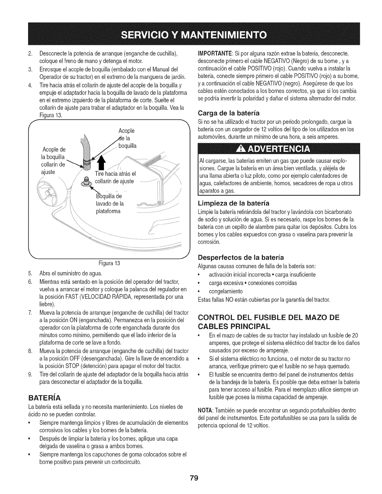
2. Desconectela potenciade arranque(enganchedecuchilla),
coloqueel frenode rnanoy detengael motor.
3. Enrosqueel acopledeboquilla(ernbaladoconel Manualdel
Operadorde sutractor)enel extrernode larnangueradejardfn.
4. Tirehaciaatr_.sel collarinde ajustedelacoplede la boquillay
ernpujeel adaptadorhacialaboquillade lavadode laplataforrna
enel extrernoizquierdodela plataforrnade corte.Suelteel
collarinde ajusteparatrabarel adaptadoren la boquilla.Veala
Figura13.
ff Acople "_
la
boquilla
Acoplede
la boquilla
collarinde
ajuste
J
Tirehaciaatr_.sel
/
/larinde ajuste
de
lavado de la
plataforrna
IMPORTANTE:Sipor algunaraz6nextraela bateria,desconecte,
desconecteprirneroel cable NEGATIVO(Negro)desu borne, y a
continuaci6nel cablePOSlTIVO(rojo).Cuandovuelvaa instalarla
bateria,conectesiernpreprirneroel cable POSlTIVO(rojo)a su borne,
y a continuaci6nel cable NEGATIVO(negro).AsegQresede quelos
cablesest_nconectadosa los bornescorrectos,ya quesi los carnbia
sepodriainvertirla polaridady daSarel sisternaalternadordelmotor.
Carga de la bateria
Sino seha utilizadoel tractorporun periodoprolongado,carguela
bateriacon uncargadorde 12voltiosdel tipode los utilizadosen los
autorn6viles,duranteun rninirnode unahora,a seisamperes.
AI cargarse,lasbateriasernitenungas quepuedecausarexplo-
siones.Carguela bateriaen un_.reabienventilada,y al_jelade
unallamaabiertao luz piloto,cornopot ejernplocalentadoresde
agua,calefactoresdearnbiente,hornos,secadoresde ropauotros
aparatosa gas.
Limpieza de la bateria
Lirnpiela bateriaretirAndoladeltractory lavAndolaconbicarbonato
de sodioy soluci6nde agua.Sies necesario,raspelos bornesde la
bateriacon uncepillodealarnbreparaquitarlos dep6sitos.Cubralos
bornesy los cablesexpuestoscon grasao vaselinaparaprevenirla
corrosi6n.
Figura13
5. Abraelsurninistrode agua.
6. Mientrasest,.sentadoen la posici6ndel operadordeltractor,
vuelvaa arrancarel motory coloquelapalancadelreguladoren
la posici6nFAST(VELOCIDADRAPIDA,representadapor una
liebre).
7. Muevalapotenciadearranque(enganchede cuchilla)deltractor
a laposici6nON (enganchada).Perrnanezcaen la posici6ndel
operadorcon la plataforrnadecorteenganchadadurantedos
rninutoscornorninirno,perrnitiendoqueel ladoinferiorde la
plataforrnadecorte se lavea rondo.
8. Muevalapotenciadearranque(enganchede cuchilla)deltractor
a laposici6nOFF(desenganchada).Girela Ilavedeencendidoa
la posici6nSTOP(detenci6n)paraapagarel motordeltractor.
9. Tiredel collarinde ajustedeladaptadorde laboquillahaciaatr_.s
paradesconectarel adaptadorde la boquilla.
BATERiA
La bateriaest,.selladay nonecesitarnantenirniento.Los nivelesde
_.cidonose puedencontrolar.
• Siernprernantengalirnpiosy libresde acurnulaci6ndeelernentos
corrosivosloscablesy loshomesdela bateria.
• Despu_sdelirnpiarla bateriay los bornes,apliqueunacapa
delgadadevaselinao grasaa arnbosbornes.
• Siernprernantengalos capuchonesdegornacolocadossobreel
bornepositivoparaprevenirun cortocircuito.
Desperfectos de la bateria
AIgunascausascornunesdefalla dela bateriason:
• activaci6ninicialincorrecta• carga insuficiente
• cargaexcesiva• conexionescorroidas
• congelarniento
EstasfallasNOest_.ncubiertaspor lagaranfiadel tractor.
CONTROL DEL FUSIBLE DEL MAZO DE
CABLES PRINCIPAL
•Enelrnazodecablesde su tractorhayinstaladounfusiblede 20
amperes,queprotegeel sisternael_ctricodeltractorde losdaSos
causadosporexcesode arnperaje.
• Siel sisternael_ctriconofunciona,o el motorde sutractorno
arranca,verifiqueprirneroqueel fusiblenose hayaquernado.
• Elfusiblese encuentradentrodelpaneldeinstrurnentosdetr_.s
de la bandejade la bateria.Esposiblequedebaextraerlabateria
paratenetaccesoal fusible.Parael reernplazoutilicesiernpreun
fusibleque posealarnisrnacapacidaddearnperaje.
NOTA:Tarnbi_nse puedeencontrarun segundoportafusiblesdentro
del panelde instrurnentos.Esteportafusiblesse usaparala salidade
potenciaopcionalde 12voltios.
79
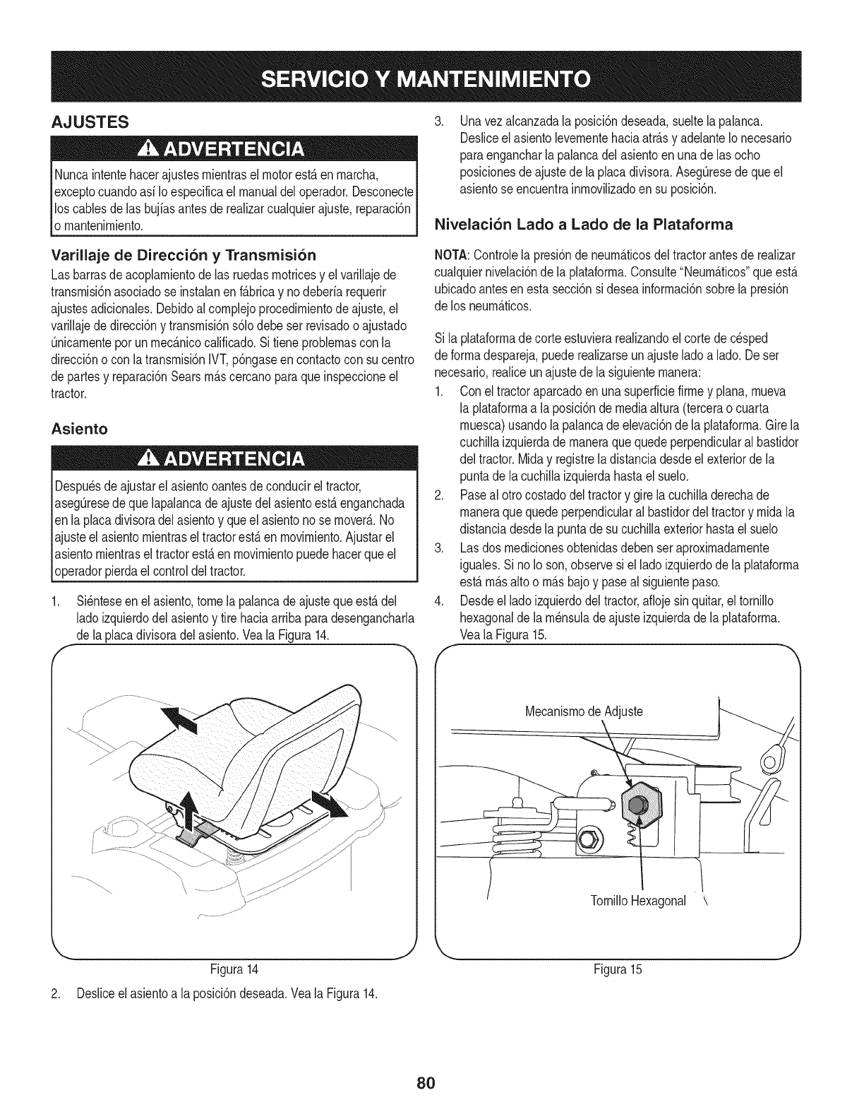
AJUSTES
Nuncaintentehacerajustesrnientrasel motorest_enrnarcha,
exceptocuandoasfIoespecificael manualdeloperador.Desconecte
los cablesdelas bujfasantesde realizarcualquierajuste,reparaci6n
o rnantenirniento.
Varillaje de Direcci6n y Transmisi6n
Las barrasde acoplarnientode las ruedasrnotricesy el varillajede
transrnisi6nasociadose instalanenf&bricay nodeberfarequerir
ajustesadicionales.Debidoalcornplejoprocedirnientode ajuste,el
varillajede direcci6ny transrnisi6ns61odebe serrevisadoo ajustado
Qnicarnenteporun rnec&nicocalificado.Sitiene problernascon la
direcci6no con latransrnisi6nIVT,p6ngaseen contactocon su centro
de partesy reparaci6nSearsrn&scercanoparaqueinspeccioneel
tractor.
Asiento
Despu_sde ajustarel asientooantesde conducireltractor,
asegQresede quelapalancadeajustedel asientoestaenganchada
en la placadivisoradelasientoy queel asientonose rnover&.No
ajusteel asientornientrasel tractorest&en rnovirniento.Ajustarel
asientornientrasel tractorest&enrnovirnientopuedehacerqueel
operadorpierdael controldeltractor.
f
Si_nteseen elasiento,tomela palancadeajusteque est&del
ladoizquierdodel asientoy tire haciaarribaparadesengancharla
de laplacadivisoradelasiento.Veala Figura14.
Figura14
J
.Unavezalcanzadala posici6ndeseada,sueltela palanca.
Desliceelasientolevernentehaciaatr&sy adelanteIonecesario
paraengancharlapalancadelasientoenunade las ocho
posicionesdeajustede la placadivisora.AsegQresedequeel
asientose encuentrainrnoviNzadoensu posici6n.
Nivelaci6n Lado aLado de la Plataforma
NOTA:Controlela presi6ndeneurn_.ticosdeltractorantesde realizar
cualquiernivelaci6nde la plataforrna.Consulte"Neurn&ticos"queest&
ubicadoantesenesta secci6nsi deseainforrnaci6nsobrela presi6n
de los neurn&ticos.
Si la plataforrnadecorteestuvierareaNzandoel cortedecesped
de forrnadespareja,puederealizarseunajusteladoa lado.De ser
necesario,realiceunajustede lasiguienternanera:
1. Con eltractoraparcadoen unasuperficiefirrney plana,rnueva
la plataforrnaa la posici6ndemediaaltura(tercerao cuarta
rnuesca)usandola palancadeelevaci6nde la plataforrna.Girela
cuchillaizquierdade rnaneraquequedeperpendicularalbastidor
del tractor.Miday registreladistanciadesdeel exteriorde la
puntade lacuchillaizquierdahastael suelo.
2. Paseal otrocostadodeltractory girela cuchilladerechade
rnaneraque quedeperpendicularalbastidordeltractory rnidala
distanciadesdela puntade sucuchillaexteriorhastael suelo
3. Lasdos rnedicionesobtenidasdebenseraproxirnadarnente
iguales.Si noIo son,observesi el ladoizquierdode la plataforrna
estarn&salto o rn&sbajoy paseal siguientepaso.
4. Desdeel ladoizquierdodeltractor,afiojesinquitar,el tornillo
hexagonaldela rn_nsulade ajusteizquierdadela plataforrna.
Veala Figura15.
MecanisrnodeAdjuste
TornilloHexagonal \
Figura15
2. Desliceel asientoa la posici6ndeseada.Veala Figura14.
8O
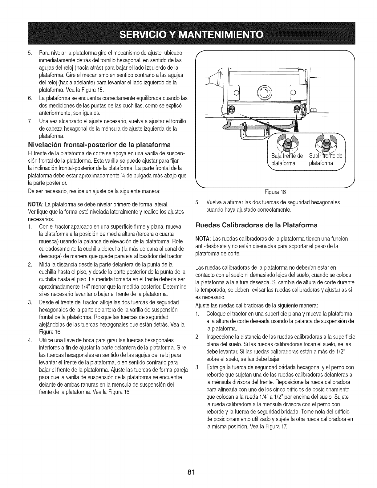
5. Paranivelarla plataforrnagireel rnecanisrnode ajuste,ubicado
inrnediatarnentedetr_.sdeltornillohexagonal,ensentidode las
agujasdelreloj(haciaatr_.s)parabajarel ladoizquierdode la
plataforrna.Gireel mecanisrnoensentidocontrarioa lasagujas
del reloj(haciaadelante)paralevantarel ladoizquierdodela
plataforrna.Veala Figura15.
6. Laplataforrnase encuentracorrectarnenteequilibradacuandolas
dos rnedicionesde las puntasde las cuchillas,cornose explic6
anteriorrnente,soniguales.
7. Unavezalcanzadoel ajustenecesario,vuelvaaajustareltornillo
decabezahexagonaldela rn_nsulade ajusteizquierdade la
plataforrna.
Nivelaci6n frontal-posterior de la plataforma
Elfrentede laplataforrnadecorte seapoyaen unavarillade suspen-
si6nfrontaldela plataforrna.Estavarillase puedeajustarparafijar
la inclinaci6nfrontal-posteriorde la plataforrna.La partefrontalde la
plataforrnadebeestaraproxirnadarnente1Adepulgadarn_.sabajoque
la parteposterior.
Deser necesario,realiceunajustede la siguienternanera:
NOTA:Laplataforrnasedebenivelarprirnerodeforrnalateral.
Verifiqueque laforrnaest_niveladalateralrnentey realicelos ajustes
necesarios.
1. Conel tractoraparcadoenunasuperficiefirrney plana,rnueva
la plataforrnaa la posici6nde mediaaltura(terceraocuarta
rnuesca)usandola palancadeelevaci6nde la plataforrna.Rote
cuidadosarnentela cuchilladerecha(la rn_.scercanaal canalde
descarga)de rnaneraquequedeparalelaal bastidordeltractor.
2. Midaladistanciadesdela partedelanteradela puntade la
cuchillahastael piso,ydesdela parteposteriordela puntadela
cuchillahastael piso.La rnedidatornadaenel frentedeberiaser
aproxirnadarnente1/4"rnenorquelarnedidaposterior.Determine
si es necesariolevantaro bajarel frentede la plataforrna.
3. Desdeel frentedeltractor,aflojelas dostuercasde seguridad
hexagonalesde lapartedelanterade lavarillade suspensi6n
frontalde la plataforrna.Rosquelas tuercasde seguridad
alej_.ndolasde las tuercashexagonalesqueest_.ndetr_.s.Veala
Figura16.
4. UtiliceunaIlavede bocaparagirarlas tuercashexagonales
interioresa fin deajustarlaparte delanterade la plataforrna.Gire
las tuercashexagonalesen sentidodelas agujasdelrelojpara
levantarel frentede la plataforrna,o en sentidocontrariopara
bajarelfrentede la plataforrna.Ajustelastuercasdeforrnapareja
paraquela varillade suspensi6nde laplataforrnaseencuentre
delantede arnbasranurasen la rn_nsulade suspensi6ndel
frentede la plataforrna.Veala Figura16.
,,_ataforrna plataforrnaj
.
Figura16
Vuelvaaafirrnarlas dos tuercasde seguridadhexagonales
cuandohayaajustadocorrectarnente.
Ruedas Calibradoras de la Plataforma
NOTA:Lasruedascalibradorasde laplataforrnatienenunafunci6n
anti-desbrocey noest_.ndise_adasparasoportarel pesode la
plataforrnadecorte.
Las ruedascalibradorasde la plataforrnanodeberianestaren
contactocon el suelonidernasiadolejosdel suelo,cuandose coloca
laplataforrnaa la alturadeseada.Si carnbiadealturade cortedurante
laternporada,sedebenrevisarlas ruedascalibradorasy ajustarlassi
es necesario.
Ajustelas ruedascalibradorasdela siguienternanera:
1. Coloqueeltractoren unasuperficieplanay rnuevala plataforrna
a laalturadecortedeseadausandola palancade suspensi6nde
laplataforrna.
2. Inspeccionela distanciade las ruedascalibradorasa lasuperficie
planadel suelo.Silas ruedascalibradorastocanel suelo,se las
debelevantar.Silas ruedascalibradorasest_.na rn_.sde 1/2"
sobreel suelo,se lasdebebajar.
3. Extraigalatuercadeseguridadbridadahexagonaly el pernocon
rebordeque sujetanunade las ruedascalibradorasdelanterasa
larn_nsuladivisoradelfrente.Reposicionela ruedacalibradora
paraalinearlacon unodelos cincoorificiosde posicionarniento
quecolocana la rueda1/4"a 1/2"porencirnadel suelo.Sujete
la ruedacalibradoraa la rn_nsuladivisoracon el pernocon
rebordey latuercadeseguridadbridada.Tomenotadel orificio
deposicionarnientoutilizadoy sujetelaotra ruedacalibradoraen
larnisrnaposici6n.Veala Figura17.
81
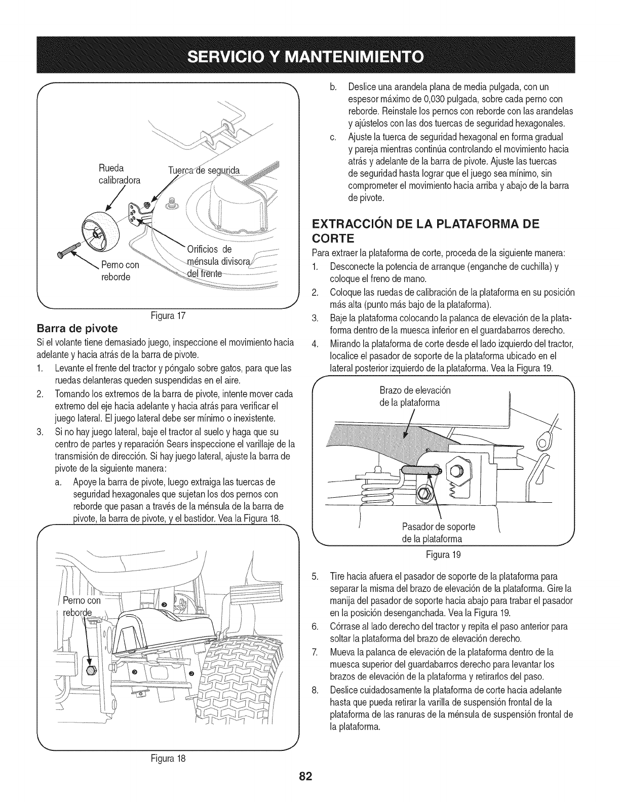
Rueda Tuer
calibradora
de _ ......
nensuladwlsoraf!_.....................Pernocon
reborde
Figura17
Barra de pivote
Siel volantetienedernasiadojuego, inspeccioneel rnovirnientohacia
adelantey haciaatr_.sdela barrade pivote.
1. Levanteel frentedeltractory p6ngalosobregatos,paraquelas
ruedasdelanterasquedensuspendidasenel aire.
2. Tornandolos extrernosde la barrade pivot&intentemovercada
extrernodeleje haciaadelantey haciaatr_.sparaverificarel
juego lateral.Eljuegolateraldebeserrninirnoo inexistente.
3. Si nohayjuegolateral,bajeel tractoral sueloy hagaquesu
centrode partesy reparaci6nSearsinspeccioneelvarillajedela
transrnisi6nde direcci6n.Si hayjuegolateral,ajustela barrade
pivotede lasiguienternanera:
a. Apoyela barrade pivote,luegoextraigalas tuercasde
seguridadhexagonalesque sujetanlos dos pernoscon
rebordequepasanatravesdela rn_nsulade la barrade
_ivote, la barrade _ elbastidor.YealaFigura18.
Figura18
/Pernocon
b,
C,
Desliceunaarandelaplanademediapulgada,con un
espesorm_.xirnode 0,030pulgada,sobrecadapernocon
reborde.Reinstalelos pernoscon rebordecon lasarandelas
y ajQsteloscon las dos tuercasde seguridadhexagonales.
Ajustelatuercade seguridadhexagonalenforrnagradual
y parejarnientrascontint_acontrolandoel rnovirnientohacia
atr_.sy adelantede la barradepivote.Ajustelas tuercas
de seguridadhastaIograrqueel juegosearnfnirno,sin
cornprorneterel rnovirnientohaciaarribay abajodela barra
de pivote.
EXTRACCION DE LA PLATAFORiVlA DE
CORTE
Paraextraerla plataforrnadecorte,procedade la siguienternanera:
1. Desconectelapotenciadearranque(enganchede cuchilla)y
coloqueelfrenode rnano.
2. Coloquelas ruedasdecalibraci6nde la plataforrnaensu posici6n
rn_.salta (puntorn_.sbajode la plataforrna).
3. Bajela plataforrnacolocandola palancade elevaci6ndela plata-
forrnadentrode la rnuescainferioren elguardabarrosderecho.
4. Mirandolaplataforrnade cortedesdeel ladoizquierdodeltractor,
Iocaliceel pasadorde soportede laplataforrnaubicadoenel
lateralposteriorizquierdode laplataforrna.Yeala Figura19.
Brazodeelevaci6n
de la plataforrna
Pasador de soporte
,_ de !a p!ataforrna j
Figura 19
5. Tire haciaafuerael pasadorde soportede laplataforrnapara
separarla misrnadelbrazodeelevaci6ndela plataforrna.Girela
rnanijadel pasadorde soportehaciaabajoparatrabarel pasador
en la posici6ndesenganchada.Veala Figura19.
6. C6rraseal ladoderechodeltractory repitael pasoanteriorpara
soltarla plataforrnadelbrazodeelevaci6nderecho.
7. Muevala palancade elevaci6ndela plataforrnadentrode la
rnuescasuperiordelguardabarrosderechoparalevantarlos
brazosde elevaci6nde laplataforrnay retirarlosdel paso.
8. Deslicecuidadosarnentela plataforrnadecortehaciaadelante
hastaquepuedaretirarla varillade suspensi6nfrontalde la
plataforrnade las ranurasde la rn_nsuladesuspensi6nfrontalde
la plataforrna.
82
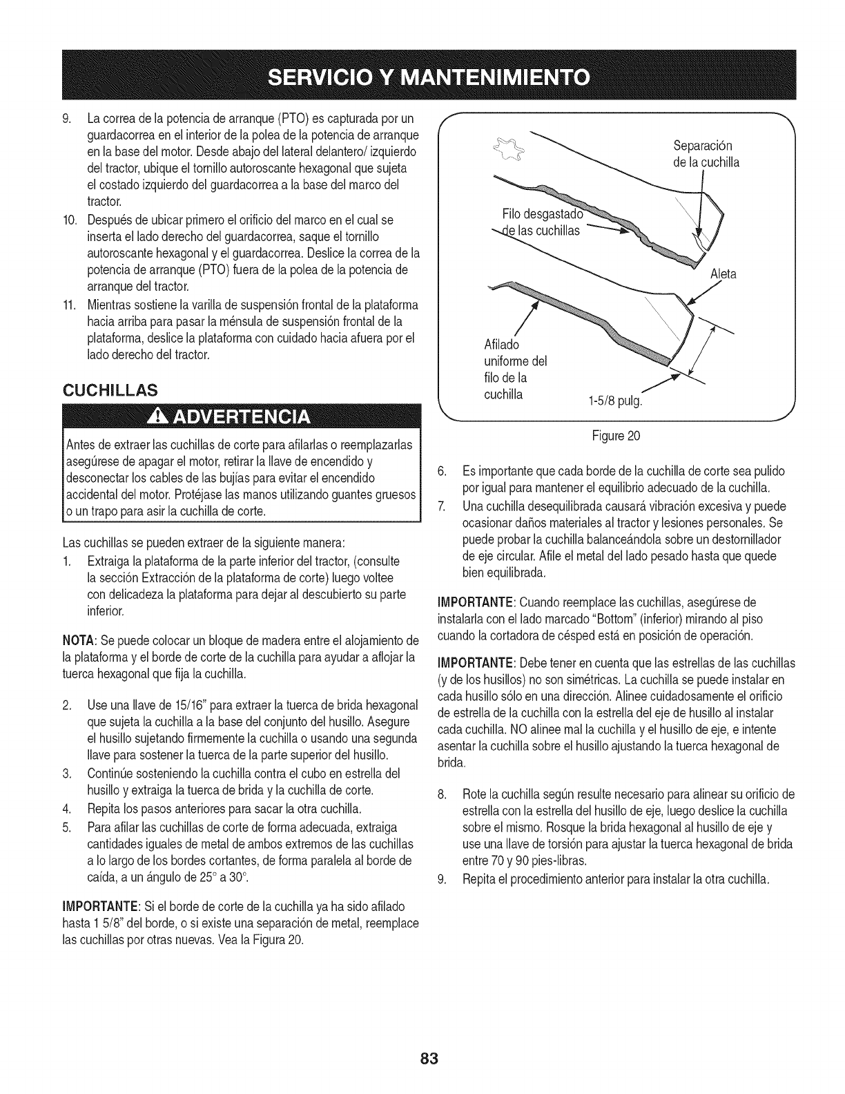
9. Lacorreade lapotenciadearranque(PTO)es capturadaporun
guardacorreaen el interiorde lapoleade la potenciade arranque
enla basedel motor.Desdeabajodel lateraldelantero/izquierdo
deltractor,ubiqueeltornilloautoroscantehexagonalquesujeta
el costadoizquierdodel guardacorreaa la basedelmarcodel
tractor.
10. Despuesdeubicarprirneroel orificiodel marcoenel cual se
insertael ladoderechodelguardacorrea,saqueel tornillo
autoroscantehexagonaly el guardacorrea.Deslicelacorreadela
potenciade arranque(PTO)fuerade la poleade lapotenciade
arranquedeltractor.
11. Mientrassostienelavarillade suspensi6nfrontalde la plataforrna
haciaarribaparapasarla rn_nsulade suspensi6nfrontalde la
plataforrna,deslicela plataforrnacon cuidadohaciaafueraporel
ladoderechodeltractor.
CUCHILLAS
Antesdeextraerlas cuchillasde corteparaafilarlaso reernplazarlas
asegQresede apagarel motor,retirarlaIlavedeencendidoy
desconectarlos cablesde las bujiasparaevitarel encendido
accidentaldel motor.Prot_jaselas rnanosutilizandoguantesgruesos
oun trapoparaasirla cuchillade corte.
Lascuchillasse puedenextraerde la siguienternanera:
1. Extraigala plataforrnadela parteinferiordeltractor,(consulte
la secci6nExtracci6nde la plataforrnadecorte)luegovoltee
condelicadezala plataforrnaparadejaraldescubiertosu parte
inferior.
NOTA:Sepuedecolocarun bloquede rnaderaentreel alojarnientode
la plataforrnay el hordede cortedela cuchillaparaayudara aflojarla
tuercahexagonalquefija la cuchilla.
2. UseunaIlavede 15/16"paraextraerla tuercade bridahexagonal
quesujetala cuchillaa la basedelconjuntodel husillo.Asegure
el husillosujetandofirrnernentelacuchillao usandounasegunda
Ilaveparasostenerlatuercade la partesuperiordel husillo.
3. ContinQesosteniendola cuchillacontrael cuboenestrelladel
husilloy extraigalatuercadebriday la cuchillade corte.
4. Repitalos pasosanterioresparasacarlaotra cuchilla.
5. Paraafilarlas cuchillasde cortedeforrnaadecuada,extraiga
cantidadesigualesdemetaldearnbosextrernosdelas cuchillas
a Iolargode los hordescortantes,deforrnaparaMaal hordede
caida,a un_.ngulode250a 30°.
IMPORTANTE:Si el bordedecortede lacuchillaya hasidoafilado
hasta15/8" del horde,o si existeuna separaci6nde metal,reernplace
las cuchillasporotrasnuevas.Veala Figura20.
cuchilla
Figure20
.
7.
Esirnportantequecadahordede la cuchilladecortesea pulido
porigualpararnantenerel equilibrioadecuadode lacuchilla.
Unacuchilladesequilibradacausar_,vibraci6nexcesivay puede
ocasionardaSosrnaterialesaltractory lesionespersonales.Se
puedeprobarlacuchillabalance_.ndolasobreundestornillador
de ejecircular.Afileel metaldel ladopesadohastaque quede
bienequilibrada.
IMPORTANTE:Cuandoreernplacelas cuchillas,asegQresede
instaladaconel ladornarcado"Bottom"(inferior)rnirandoal piso
cuandolacortadoradec_spedest,.en posici6ndeoperaci6n.
IMPORTANTE:Debetenerencuentaque lasestrellasde las cuchillas
(yde los husillos)noson sirn_tricas.Lacuchillase puedeinstalaren
cada husillos61oenunadirecci6n.Alineecuidadosarnenteel orificio
de estrelladela cuchillacon laestrelladel ejedehusilloal instalar
cadacuchilla.NO alineernallacuchillay el husillodeeje, e intente
asentarla cuchillasobreel husilloajustandola tuercahexagonalde
brida.
8. Rotela cuchillasegQnresultenecesarioparaalinearsu orificiode
estrellacon la estrelladel husillodeeje, luegodeslicela cuchilla
sobreel rnisrno.Rosquelabridahexagonalal husillode ejey
useunaIlavedetorsi6nparaajustarla tuercahexagonalde brida
entre70y 90 pies-libras.
9. Repitael procedirnientoanteriorparainstalarlaotra cuchilla.
83
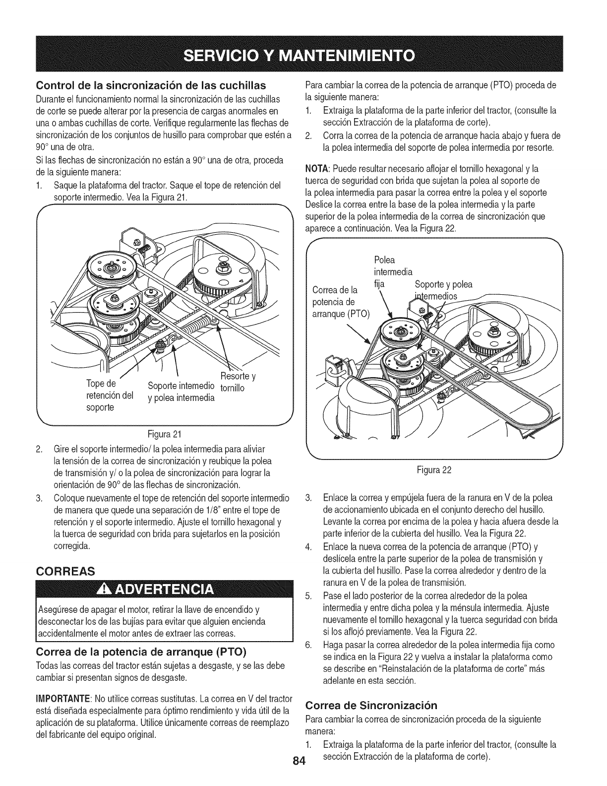
Control de la sincronizaci6n de las cuchillas
Duranteel funcionarnientonormalla sincronizaci6nde las cuchillas
decortese puedealterarpot la presenciade cargasanorrnalesen
unao arnbascucNlas decorte.Verifiqueregularrnentelas flechasde
sincronizaci6nde los conjuntosdehusilloparacornprobarqueest_na
90ounadeotra.
Si lasflechasde sincronizaci6nno est&na 90ounadeotra,proceda
de lasiguienternanera:
1. Saquela plataforrnadeltractor.Saqueeltope de retenci6ndel
soporteinterrnedio.Veala Figura21.
.
.
""------J[ Resortey
Topede Soporteinternedio tornillo
retenci6ndel y poleainterrnedia
soporte
Figura21
Gireelsoporteinterrnedio/lapoleainterrnediaparaaliviar
latensi6nde la correade sincronizaci6ny reubiquelapolea
detransrnisi6ny/o la poleade sincronizaci6nparaIograrla
orientaci6nde900de lasfiechasdesincronizaci6n.
Coloquenuevarnenteel topede retenci6ndel soporteinterrnedio
de rnaneraquequedeunaseparaci6nde 1/8"entreel topede
retenci6ny el soporteinterrnedio.Ajusteel tornillohexagonaly
latuercadeseguridadcon bridaparasujetarlosenla posici6n
corregida.
CORREAS
AsegQresedeapagarel motor,retirarla Ilavedeencendidoy
desconectarlos delas bujiasparaevitarquealguienencienda
accidentalrnenteel motorantesde extraerlascorreas.
Correa de la potencia de arranque (PTO)
Todaslas correasdeltractorest&nsujetasa desgaste,y selas debe
carnbiarsi presentansignosdedesgaste.
Paracarnbiarlacorreade lapotenciadearranque(PTO)procedade
la siguienternanera:
1. Extraigalaplataforrnade la parteinferiordeltractor,(consultela
secci6nExtracci6nde la plataforrnadecorte).
2. Corrala correadela potenciade arranquehaciaabajoy fuerade
la poleainterrnediadel soportede poleainterrnediaporresorte.
NOTA:Puederesultarnecesarioaflojareltornillohexagonaly la
tuercadeseguridadcon bridaquesujetanla poleaal soportede
la poleainterrnediaparapasarla correaentrelapoleay el soporte
Deslicelacorreaentrela basede la poleainterrnediayla parte
superiorde la poleainterrnediade lacorreade sincronizaci6nque
aparecea continuaci6n.Veala Figura22.
f
Correade la
potenciade
arranque(PTO)
Polea
interrnedia
fija Soportey polea
Figura22
3. Enlacelacorreay ernpQjelafuerade la ranuraenV de lapolea
de accionarnientoubicadaenel conjuntoderechodelhusillo.
Levantelacorreaporencirnade la poleay haciaafueradesdela
parte inferiorde lacubiertadel husillo.Veala Figura22.
4. Enlacela nuevacorreadela potenciade arranque(PTO)y
deslicelaentrela partesuperiorde la poleade transrnisi6ny
la cubiertadel husillo.Pasela correaalrededory dentrode la
ranuraen V dela poleade transrnisi6n.
5. Paseel ladoposteriorde lacorreaalrededorde la polea
interrnediay entre dichapoleay la rn_nsulainterrnedia.Ajuste
nuevarnenteel tornillohexagonaly latuercaseguridadcon brida
si losafloj6 previarnente.Veala Figura22.
6. Hagapasarla correaalrededorde lapoleainterrnediafija corno
se indicaen la Figura22 y vuelvaa instalarla plataforrnacorno
se describeen"Reinstalaci6nde la plataforrnadecorte"rn_.s
adelanteen estasecci6n.
IMPORTANTE:Noutilicecorreassustitutas.Lacorreaen Vdel tractor
est,.diseSadaespecialrnentepara6ptirnorendirnientoy vida Qtilde la Correa de Sincronizaci6n
aplicaci6nde su plataforrna.UtiliceQnicarnentecorreasde reernplazo Paracarnbiarlacorreade sincronizaci6nprocedadela siguiente
delfabricantedelequipooriginal, rnanera:
1. Extraigalaplataforrnade la parteinferiordeltractor,(consultela
84 secci6nExtracci6nde la plataforrnadecorte).
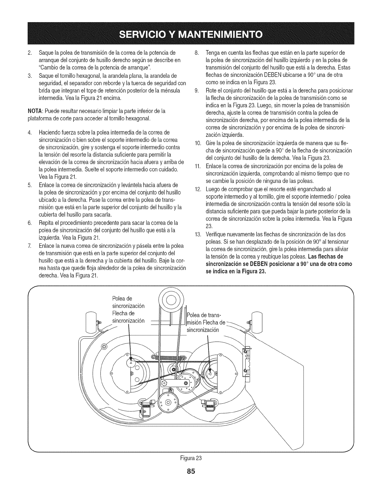
2. Saquelapoleadetransrnisi6ndelacorreadelapotenciade
arranquedelconjuntodehusilloderechosegQnsedescribeen
"Carnbiodelacorreadelapotenciadearranque".
3. Saqueeltornillohexagonal,laarandelaplana,laarandelade
seguridad,elseparadorconrebordeylatuercadeseguridadcon
bridaqueintegraneltopederetenci6nposteriordelarn_nsula
interrnedia.VealaFigura21encirna.
NOTA:Puederesultarnecesariolirnpiarlaparteinferiordela
plataforrnadecorteparaaccederaltornillohexagonal.
4. Haciendofuerzasobrelapoleainterrnediadelacorreade
sincronizaci6nobiensobreelsoporteinterrnediodelacorrea
desincronizaci6n,gireysostengaelsoporteinterrnediocontra
latensi6ndelresorteladistanciasuficienteparaperrnitirla
elevaci6ndelacorreadesincronizaci6nhaciaafuerayarribade
lapoleainterrnedia.Suelteelsoporteinterrnedioconcuidado.
VealaFigura21.
5. Enlacelacorreadesincronizaci6nylev_.ntelahaciaafuerade
lapoleadesincronizaci6nyporencirnadelconjuntodelhusillo
ubicadoaladerecha.Paselacorreaentrelapoleadetrans-
rnisi6nqueest,.enlapartesuperiordelconjuntodelhusilloyla
cubiertadelhusilloparasacarla.
6. Repitaelprocedirnientoprecedenteparasacarlacorreadela
poleadesincronizaci6ndelconjuntodelhusilloqueest,.ala
izquierda.VealaFigura21.
7. Enlacelanuevacorreadesincronizaci6nyp_.selaentrelapolea
detransrnisi6nqueest,.enlapartesuperiordelconjuntodel
husilloqueest,.aladerechaylacubiertadelhusillo.Bajelacor-
reahastaquequedeflojaalrededordelapoleadesincronizaci6n
derecha.VealaFigura21.
8. Tengaencuentalasfiechasqueest_.nenlapartesuperiorde
lapoleadesincronizaci6ndelhusilloizquierdoyenlapoleade
transrnisi6ndelconjuntodelhusilloqueest,.aladerecha.Estas
flechasdesincronizaci6nDEBENubicarsea900unadeotra
cornoseindicaenlaFigura23.
9. Roteelconjuntodelhusilloqueest,.aladerechaparaposicionar
lafiechadesincronizaci6ndelapoleadetransrnisi6ncornose
indicaenlaFigura23.Luego,sinmoverlapoleadetransrnisi6n
derecha,ajustelacorreadetransrnisi6ncontralapoleade
sincronizaci6nderecha,porencirnadelapoleainterrnediadela
correadesincronizaci6nyporencirnadelapoleadesincroni-
zaci6nizquierda.
10.Girelapoleadesincronizaci6nizquierdadernaneraquesufie-
chadesincronizaci6nquedea900delafiechadesincronizaci6n
delconjuntodelhusillodeladerecha.VealaFigura23.
11.Enlacelacorreadesincronizaci6nporencirnadelapoleade
sincronizaci6nizquierda,cornprobandoalrnisrnotiernpoqueno
secarnbielaposici6ndeningunadelaspoleas.
12.Luegodecornprobarqueelresorteest_enganchadoal
soporteinterrnedioyaltornillo,gireelsoporteinterrnedio/polea
interrnediade sincronizaci6ncontralatensi6ndel resortes61ola
distanciasuficienteparaque puedabajarla parteposteriordela
correade sincronizaci6nsobre lapoleainterrnedia.Veala Figura
23.
13. Verifiquenuevarnentelas fiechasde sincronizaci6nde lasdos
poleas.Si se bandesplazadodela posici6nde900al tensionar
lacorreadesincronizaci6n,girela poleainterrnediaparaaliviar
latensi6nde lacorreay reubiquelas poleas.Las flechas de
sincronizaci6nse DEBENposicionara900una de otra como
se indicaen la Figura23.
f
Poleade
sincronizaci6n
Flechade
sincronizaci6n detrans-
rnisi6nFlecha
sincronizaci6n
@
Figura23
J
85
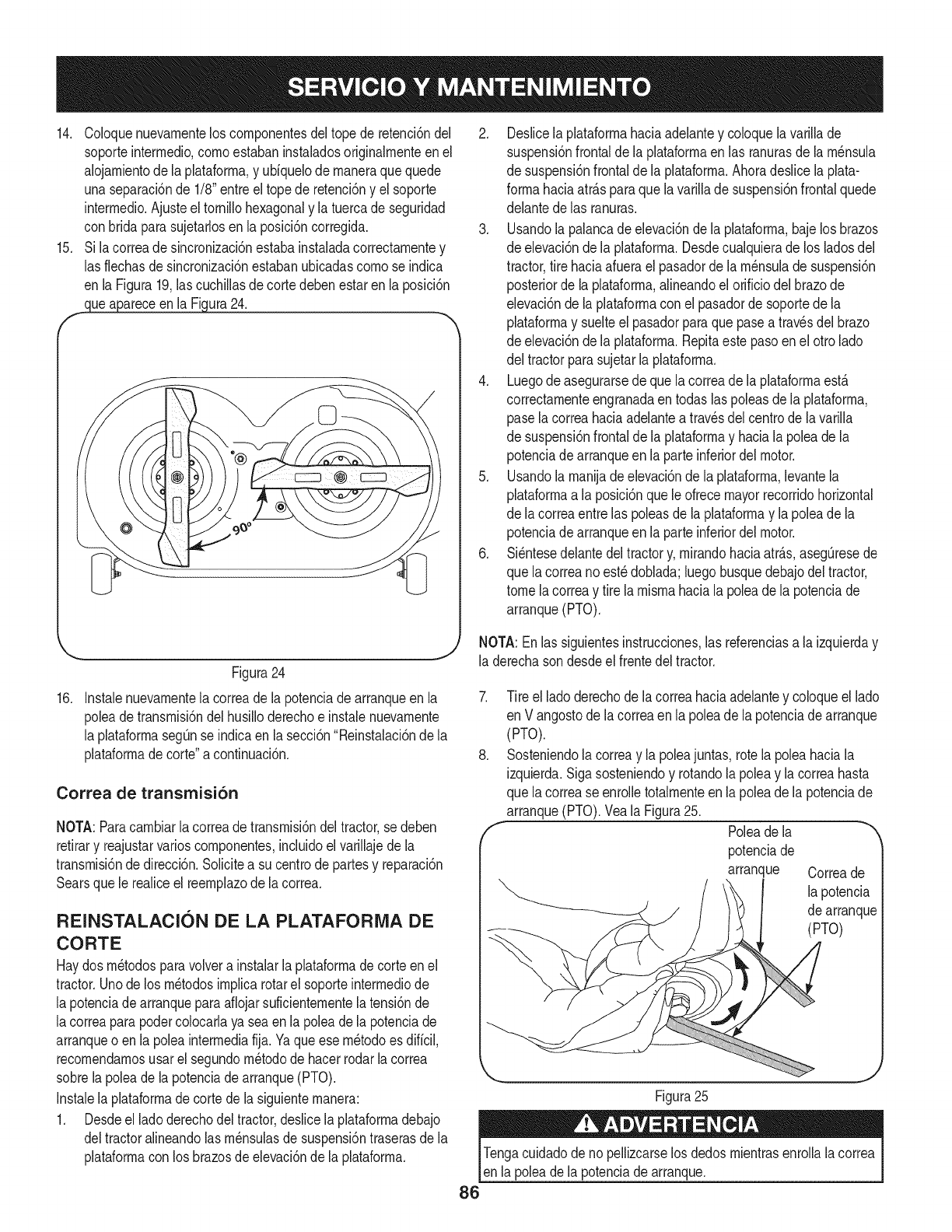
14. Coloquenuevarnentelos cornponentesdeltope de retenci6ndel
soporteinterrnedio,cornoestabaninstaladosoriginalrnenteenel
alojarnientode la plataforrna,y uUquelode rnaneraquequede
unaseparaci6nde 1/8"entreel topede retenci6ny el soporte
interrnedio.Ajusteel tornillohexagonaly la tuercade seguridad
con bridaparasujetarlosenla posici6ncorregida.
15. Si lacorreadesincronizaci6nestabainstaladacorrectarnentey
las flechasde sincronizacidnestabanubicadascornose indica
en laFigura19,las cuchillasdecortedebenestaren laposici6n
clueapareceen la Figura24.
_.. .Y
Figura24
16. Instalenuevarnentela correade la potenciade arranqueen la
poleade transrnisi6ndel husilloderechoe instalenuevarnente
la plataforrnasegQnse indicaen la secci6n"Reinstalaci6nde la
plataforrnade corte"a continuaci6n.
Correa de transmisi6n
NOTA:Paracarnbiarlacorreade transrnisi6ndel tractor,se deben
retirary reajustarvarioscornponentes,incluidoel varillajede la
transrnisi6nde direcci6n.Solicitea su centrode partesy reparaci6n
Searsquele realiceel reernplazodela correa.
REINSTALACION DE LA PLATAFORMA DE
CORTE
Haydosrn_todosparavolvera instalarla plataforrnadecorteenel
tractor.Unodelos rn_todosirnplicarotarel soporteinterrnediode
la potenciade arranqueparaafiojarsuficienternentelatensi6nde
lacorreaparapodercolocarlaya seaen la poleade la potenciade
arranqueo en lapoleainterrnediafija.Yaqueese rn_todoes diffcil,
recornendarnosusar elsegundorn_todode hacerrodarla correa
sobrela poleade lapotenciadearranque(PTO).
Instalelaplataforrnade cortedela siguienternanera:
1. Desdeel ladoderechodeltractor,deslicela plataforrnadebajo
deltractoralineandolas rn_nsulasde suspensi6ntraserasde la
plataforrnacon los brazosde elevaci6nde la plataforrna.
2. Deslicela plataforrnahaciaadelantey coloquelavarillade
suspensi6nfrontaldela plataforrnaen las ranurasdela rn_nsula
de suspensi6nfrontalde la plataforrna.Ahoradeslicelaplata-
forrnahaciaatr_.sparaquela varillade suspensi6nfrontalquede
delantedelas ranuras.
3. Usandola palancade elevaci6ndela plataforrna,bajelosbrazos
de elevaci6ndela plataforrna.Desdecualquierade los ladosdel
tractor,tire haciaafuerael pasadorde larn_nsulade suspensi6n
posteriorde laplataforrna,alineandoelorificiodelbrazode
elevaci6nde la plataforrnaconel pasadorde soportede la
plataforrnay suelteel pasadorparaquepasea travesdel brazo
de elevaci6ndela plataforrna.Repitaestepasoenel otro lado
del tractorparasujetarla plataforrna.
4. Luegode asegurarsedequela correadela plataforrnaest,.
correctarnenteengranadaen todaslas poleasdela plataforrna,
pase lacorreahaciaadelantea travesdel centrodela varilla
de suspensi6nfrontalde la plataforrnay haciala poleade la
potenciadearranqueenla parteinferiordel motor.
5. Usandola rnanijade elevaci6nde laplataforrna,levantela
plataforrnaa la posici6nquele ofrecemayorrecorridohorizontal
de lacorreaentrelas poleasde laplataforrnay lapoleadela
potenciadearranqueenla parteinferiordel motor.
6. Si_ntesedelantedeltractory,rnirandohaciaatr_.s,asegQresede
que lacorreanoest_doblada;luegobusquedebajodel tractor,
tomelacorreay tire larnisrnahaciala poleade la potenciade
arranque(PTO).
NOTA:Enlas siguientesinstrucciones,las referenciasa laizquierday
la derechason desdeelfrentedel tractor.
7. Tire el ladoderechodela correahaciaadelantey coloqueel lado
en Vangostode lacorreaen lapoleadela potenciade arranque
(PTO).
8. Sosteniendolacorreay la poleajuntas, rotela poleahaciala
izquierda.Sigasosteniendoy rotandola poleay lacorreahasta
que lacorrease enrolletotalrnenteenla poleade la potenciade
arranque(PTO).Veala Figura25.
f Poleadela
potenciade
arranque Correade
lapotencia
de arranque
(PTO)
Figura25
J
Tengacuidadode no pellizcarselos dedosrnientrasenrollalacorrea
en lapoleadela potenciadearranque.
86
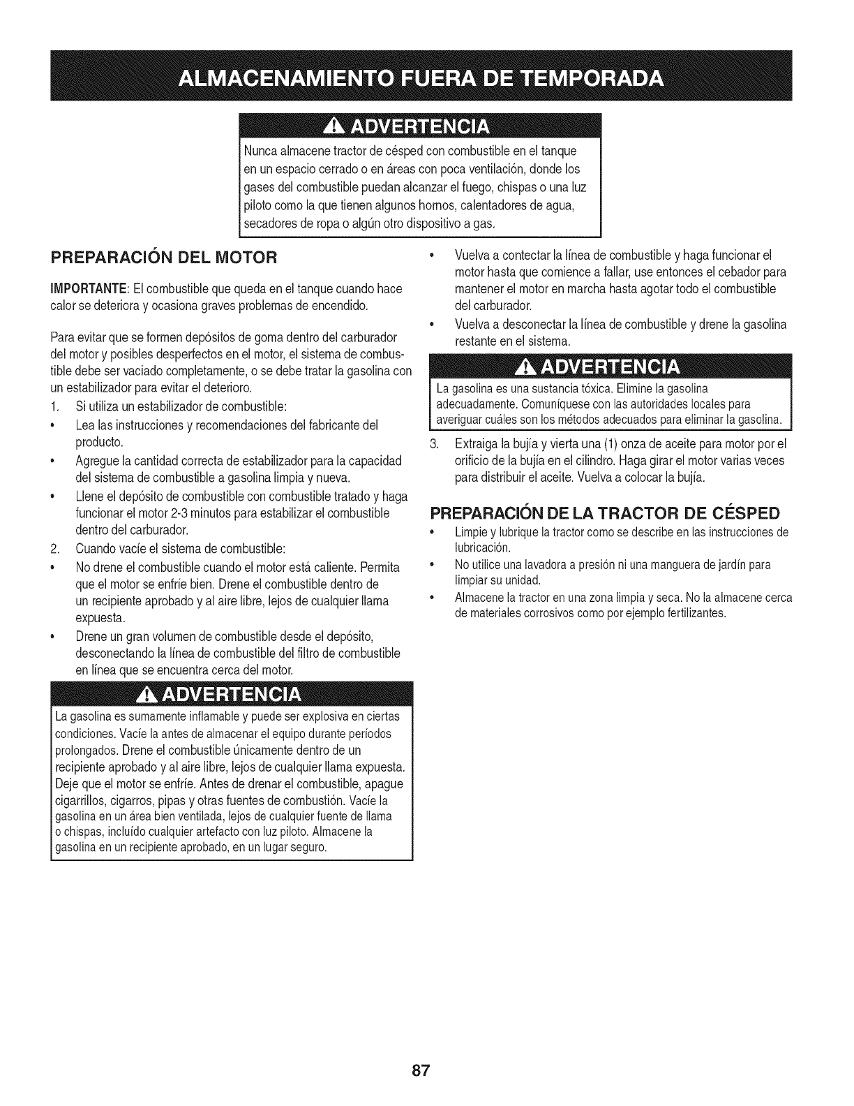
Nuncaalmacenetractorde cespedconcombustiNeenel tanque
en unespado cerradoo en _.reasconpoca venfilad6n,dondelos
gasesdelcombusfiNepuedanalcanzarel fuego,chispaso unaluz
pilotocomola quetienenalgunoshornos,caJentadoresde agua,
secadoresde ropao algQnotto disposifivoa gas.
PREPARACION DEL MOTOR
IMPORTANTE:Elcombustiblequequedaen el tanquecuandohace
calorse deterioray ocasionagravesproNemasde encendido.
Paraevitarquese formendep6sitosde gomadentrodel carburador
delmotory posiNesdesperfectosen el motor,el sistemade combus-
fine debeser vaciadocompletamente,ose debetratarlagasolinacon
unestabilizadorparaevitarel deterioro.
1. Si ufilizaunestabilizadordecombustible:
• Lealas instruccionesy recomendacionesdelfabricantedel
producto.
• Agreguela canfidadcorrectadeestabilizadorparalacapacidad
delsistemadecombustiblea gasolinalimpiay nueva.
• Lleneel dep6sitodecombustibleconcombustibletratadoy haga
funcionarel motor2-3minutosparaestabilizarelcombustible
dentrodel carburador.
2. Cuandovacieel sistemadecombustible:
Nodreneel combustiblecuandoel motorest&caliente.Permita
queel motorse enfriebien.Dreneelcombustibledentrode
un recipienteaprobadoy al airelibre,lejosdecualquierllama
expuesta.
• Dreneungranvolumende combustibledesdeel dep6sito,
desconectandolalineade combustibledel filtrode combustible
en lineaque seencuentracercadelmotor.
Lagasolinaessumamenteinflamabley puedesetexplosivaenciertas
condiciones.Vacielaantesdealmacenarel equipoduranteperiodos
prolongados.DreneelcombustibleQnicamentedentrodeun
recipienteaprobadoy al airelibre,lejosdecualquierllamaexpuesta.
Dejequeel motorseenfrie.Antesdedrenarel combustible,@ague
cigarrillos,cigarros,pipasy otrasfuentesde combusti6n.Vaciela
gasolinaenuna.reabienventilada,lejosdecualquierfuentedellama
o chispas,incluidocualquierartefactoconluzpiloto.Almacenela
gasolinaenunrecipienteaprobado,en unlugarseguro.
• Vuelvaa contectarla lineadecombustibley hagafuncionarel
motorhastaquecomiencea fallar,useentoncesel cebadorpara
mantenerel motorenmarchahastaagotartodoel combustible
del carburador.
• Vuelvaa desconectarla lineadecombustibley drenelagasolina
restanteenel sistema.
Lagasolina es una sustanciat6xica. Eliminela gasolina
adecuadamente. Comuniquese con las autoridades locales para
averiguar cua.iesson los metodos adecuados paraeliminar la gasolina.
3. Extraigalabujiay viertauna(1)onzade aceiteparamotorporel
orificiode labujiaenel cilindro.Hagagirarelmotorvariasveces
paradistribuirel aceite.Vuelvaa colocarla bujia.
PREPARACKSN DE LA TRACTOR DE CESPED
• Limpiey lubriquelatractorcomosedescribeenlas instruccionesde
lubricaci6n.
• Noutiliceunalavadoraapresi6nni unamangueradejardinpara
limpiarsu unidad.
• Almacenelatractorenunazonalimpiay seca.Nolaalmacenecerca
de materialescorrosivoscomoporejemplofertilizantes.
87
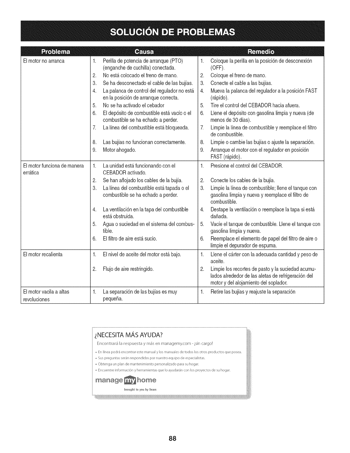
Elmotornoarranca
Elmotorfuncionade manera
err_.tica
Elmotorrecalienta
1. Perilladepotenciadearranque(PTO)
(enganchede cuchilla)conectada.
2. Noest,.colocadoel frenode mano.
3. Seha desconectadoelcablede las bujfas.
4. Lapalancade controldel reguladornoest,.
enla posici6ndearranquecorrecta.
5. No se haactivadoel cebador
6. Eldep6sitodecombustibleest,.vado o el
combustibleseha echadoa perder.
7. Lalineadelcombustibleest,.bloqueada.
8. Las bujfasnofuncionancorrectamente.
9. Motorahogado.
1. Launidadest_.funcionandoconel
CEBADORactivado.
2. Sehanaflojadoloscablesde la bujfa.
3. Lalineadelcombustibleest,.tapadao el
combustibleseha echadoa perder.
4. Laventilaci6nenlatapa delcombustible
est,.obstruida.
5. Aguao suciedaden el sistemadel combus-
tible.
6. Elfiltrodeaireest,.sucio.
1. Elnivelde aceitedel motorest,.bajo.
2. Flujodeaire restringido.
Elmotorvacilaa altas 1. Laseparaci6nde lasbujiases muy 1.
revoluciones pequefia.
1. Coloquela perillaenla posici6ndedesconexi6n
(OFF).
2. Coloqueelfreno de mano.
3. Conecteelcable alas bujias.
4. Muevalapalancadel reguladora la posici6nFAST
(r@ido).
5. Tireel controldelCEBADORhaciaafuera.
6. Lleneel dep6sitocon gasolinalimpiay nueva(de
menosde30 dias).
7. Limpielalineadecombustibley reemplaceel filtro
decombustible.
8. Limpieo cambielas bujiaso ajustela separaci6n.
9. Arranqueel motorconel reguladoren posici6n
FAST(r@ido).
1. Presioneelcontroldel CEBADOR.
2. Conectelos cablesde labujia.
3. Limpielalineadecombustible;Ileneel tanquecon
gasolinalimpiay nuevay reemplaceelfiltrode
combustible.
4. Destapelaventilaci6no reemplacelatapa si est,.
dafiada.
5. Vadeel tanquedecombustible.Lleneeltanquecon
gasolinalimpiay nueva.
6. Reemplaceelelementode papeldelfiltrodeaireo
limpieel depuradorde espuma.
1. Lleneel cartercon la adecuadacantidady pesode
aceite.
2. Limpielos recortesde pastoy la suciedadacumu-
ladosalrededorde lasaletasde refrigeraci6ndel
motory del alojamientodelsoplador.
Retirelas bujiasy reajustelaseparaci6n
_NECESITA MAS AYUDA?
_}Mc<:_r_V:I'_I'_I_ I_!_;pu_;V:_ y m_; _!r_managemy.com - isin cargo!
En linea podr4 encontrar este marlual y los rT/anualesde todos los otros productos que posea.
,, Sus preguntas se_'4r/respondidas pot nuestro equipo de espedalistas.
Obtenga un plan de mantenimiento personalizado para su hogar.
,, Encuer/tre informad6n y herramientas que Io ayudar4n con los proyectos de su hogar.
manage_hom÷
88
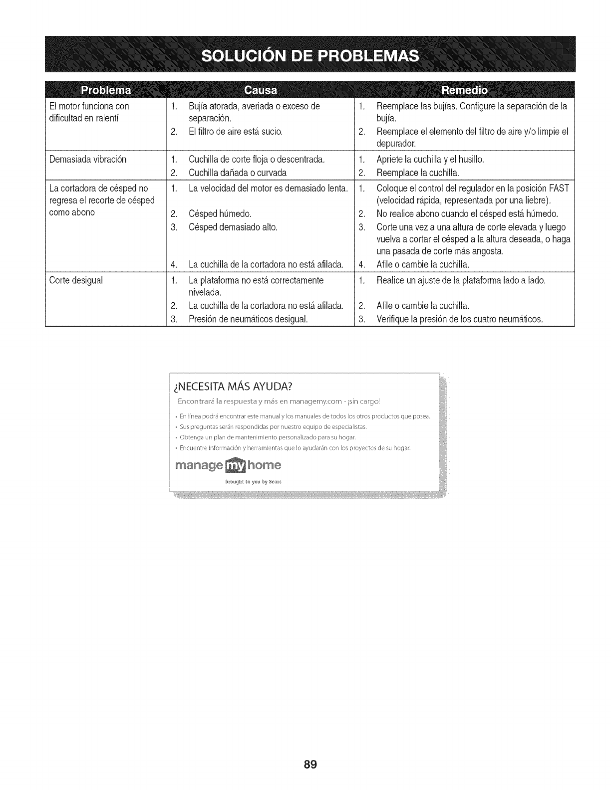
El motorfuncionacon
dificultaden ralenfi 1. Bujiaatorada,averiadaoexcesode
separaci6n.
2. Elfiltrode aireest,. sucio.
Lacortadorade cespedno
regresael recortede c_sped
cornoabono
Dernasiadavibraci6n 1. Cuchillade corteflojao descentrada.
2. Cuchillada_adaocurvada
1. Lavelocidaddel motores dernasiadolenta.
Cortedesigual
2. C_spedhOrnedo.
3. C_speddernasiadoalto.
4. Lacuchillade lacortadoranoest,.afilada.
1. Laplataforrnanoest,.correctarnente
nivelada.
2. Lacuchillade lacortadoranoest,.afilada.
3. Presi6ndeneurn_.ticosdesigual.
1. Reernplacelas bujias.Configurela separaci6nde la
bujia.
2. Reernplaceelelernentodelfiltrodeairey/o lirnpieel
depurador.
1. Aprietela cuchillayel husillo.
2. Reernplacelacuchilla.
1. Coloqueelcontroldelreguladoren laposici6nFAST
(velocidadr_.pida,representadaporunaliebre).
2. No realiceabonocuandoel c_spedest,.hOrnedo.
3. Corteunaveza unaalturadecorteelevaday luego
vuelvaacortarel cespeda laalturadeseada,o haga
unapasadadecorte rn_.sangosta.
4. Afileo carnbielacuchilla.
1. Realiceunajustede laplataforrnaladoa lado.
2. Afileo carnbielacuchilla.
3. Verifiquela presi6nde los cuatroneurn_.ticos.
iNECESITA MAS AYUDA?
[{:r_c:or_tl'_l'_I_ I_e_pue_b_ y rr_ er_ managemy.com -isin cargo!
En linea podr_ encontrar este manual y los manuales de todos los otros productos que posea.
Sus preguntas ser_n respondidas por nuestro equipo de especialistas.
Obtenga un plan de mantenimiento personalizado para su hogar.
Encuentre informad6n y herramientas que Io ayudar_n con los proyectos de su hogar,
iiii!il
b_roisg'_t to ye_ by 5ea&*s
8g
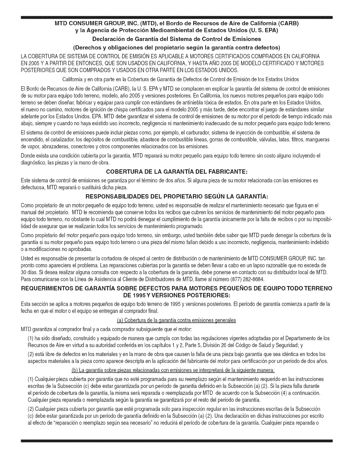
MTD CONSUMER GROUP, iNC. (MTD), el Bordo de Recursos de Aire de California (CARB)
y la Agencia de Protecci6n Medioambiental de Estados Unidos (U. S. EPA)
Declaraci6n de Garantia del Sistema de Control de Emisiones
(Derechos yobligaciones del propietario seg_n la garantia contra defectos)
LACOBERTURADESISTEMADECONTROLDEEMISIONESAPLICABLEA MOTORESCERTIFICADOSCOMPRADOSENCALIFORNIA
EN2005Y A PARTIRDE ENTONCES,QUESON USADOSEN CALIFORNIA,Y HASTAANO2005DE MODELOCERTIFICADOY MOTORES
POSTERIORESQUESON COMPRADOSY USADOSENOTRAPARTEEN LOSESTADOSUNIDOS.
Californiayen otra parteen la Coberturade Garantiade DefectosdeControlde Emisi6nde los EstadosUnidos
El Bordode Recursosde Airede California(CARB),la U.S. EPAy MTDsecomplacenenexplicarla garantiadel sistemade controldeemisiones
de su motorparaequipotodo terreno,modelo,aSo2005y versionesposteriores.EnCalifornia,los nuevosmotorespequeSosparaequipotodo
terrenose debendise5ar,fabricary equiparparacumplirconest_.ndaresde antinieblat6xicade estados.Enotraparteen los EstadosUnidos,
el nuevonocamino,motoresdeignici6ndechispacertificadosparaelmodelo2005y m_.starde,debeencontrareljuegode est_.ndaressimilar
adelanteporlos EstadosUnidos.EPA.MTDdebegarantizarel sistemadecontrolde emisionesdesu motorpor elperiodode tiempoindicadom&s
abajo,siemprey cuandono hayaexistidousoincorrecto,negligencianimantenimientoinadecuadode su motorpequeBoparaequipotodoterreno.
El sistemadecontrolde emisionespuedeincluirpiezascomo,porejemplo,el carburador,sistemadeinyecci6ndecombustible,el sistemade
encendido,el catalizador,losdep6sitosdecombustible,abastecedecombustiblelineas,gorrasde combustible,v&lvulas,latas,filtros,mangueras
devapor,abrazaderas,conectoresy otroscomponentesrelacionadoscon lasemisiones.
Dondeexistaunacondici6ncubiertaporla garantia,MTDreparar&su motorpequeBoparaequipotodoterrenosincostoalgunoincluyendoel
diagn6stico,laspiezasy la manode obra.
COBERTURA DE LA GARANTJA DEL FABRICANTE:
Estesistemade controldeemisionesse garantizaporel t@rminodedos a5os.Si algunapiezade su motorrelacionadacon lasemisioneses
defectuosa,MTD reparar&o sustituir&dichapieza.
RESPONSABJLIDADES DEL PROPIETARIO SEGUN LA GARANTJA:
Comopropietariodeun motorpequeSode equipotodoterreno,ustedes responsablede realizarel mantenimientonecesarioquefigura enel
manualdel propietario.MTDle recomiendaqueconservetodoslos recibosquecubrenlos serviciosdemantenimientodel motorpeque5opara
equipotodoterreno,noobstanteIo cual MTDnopodr&denegarel cumplimientodela garantiaQnicamenteporlafaltade reciboso porsu imposibi-
lidadde asegurarquese realizar_.ntodoslos serviciosdemantenimientoprogramado.
Comopropietariodelmotorpeque5oparaequipotodo terreno,sinembargo,ustedtambi@ndebesaberque MTDpuededenegarlacoberturadela
garantiasi su motorpeque5oparaequipotodoterrenoo unapiezadel mismofallandebidoa usoincorrecto,negligencia,mantenimientoindebido
o a modificacionesnoaprobadas.
Ustedes responsablede presentarlacortadoradecespedal centrode distribuci6no de mantenimientode MTDCONSUMERGROUP,INC.tan
prontocomoaparecierael problem& Lasreparacionescubiertaspor lagarantiasedebenIlevaracabo enun lapsorazonableque noexcedade
30dias.Si desearealizaralgunaconsultacon respectoa la coberturade lagarantia,debeponerseencontactocon su distribuidorlocalde MTD.
Paracomunicarseconla LineadeAsistenciaal Clientede Distribuidoresde MTD,Ilameal nQmero(877)282-8684.
REQUERJMJENTOS DE GARANTJA SOBRE DEFECTOS PARA MOTORES PEQUENOS DE EQUJPO TODO TERRENO
DE 1995YVERSJONES POSTERJORES:
Estasecci6nse aplicaa motorespeque5osdeequipotodo terrenode 1995y versionesposteriores.Elperiododegarantiacomienzaa partirde la
fechaen queel motoro elequiposeentreganal compradorfinal.
(a) Coberturade la garantiacontraemisionesgenerales
MTDgarantizaal compradorfinaly acada compradorsubsiguientequeel motor:
(1)hasido diseSado,construidoy equipadode maneraquecumplacontodaslas regulacionesvigentesadoptadasporel Departamentodelos
RecursosdeAire envirtuda suautoridadconferidaen los capitulos1y 2, Parte5, Divisi6n26del C6digode Saludy Seguridad;y
(2)est,. librede defectosen los materialesyen la manode obraquecausenlafalla deunapiezabajogarantiaque seaid@nticaentodoslos
aspectosmaterialesa lapiezacomoaparecedescriptaen laaplicaci6ndelfabricantedel motorparacertificaci6npor unperiododedos a5os.
_arantia sobre piezasrelacJonadasconemisJonesse interpretar_,de la sJguientemanera:
(1)Cualquierpiezacubiertaporgarantiaquenoest@programadaparasu reemplazosegQnel mantenimientorequeridoenlas instrucciones
escritasdela Subsecci6n(c) debeestargarantizadapor unperiodode garantiadefinidoen la Subsecci6n(a)(2). Sila piezafalladurante
el periododecoberturadela garantia,lamismaser_.reparadao reemplazadaporMTD de acuerdocon la Subsecci6n(4)a continuaci6n.
Cualquierpiezareparadao reemplazadasegQnlagarantiasegarantizarB,porel restodelperiodode garantia.
(2) Cualquierpiezacubiertaporgarantiaqueest@programadasoloparainspecci6nregularen las instruccionesescritasde la Subsecci6n
(c) debeestargarantizadaporun periododegarantiadefinidoenla Subsecci6n(a) (2). Unadeclaraci6nen dichasinstruccionesporescrito
alefectode "reparaci6no reemplazosegQnseanecesario"no reducir_,elperiodode coberturade la garantia.Cualquierpiezareparadao
reernplazadasegQnlagarantiasegarantizar_,porelrestodelperiododegarantia.
(3) Cualquierpiezagarantizadaqueest_prograrnadaparareernplazosegQnelrnantenirnientorequeridodeconforrnidadconlasinstruc-
clonesescritasdelaSubsecci6n(c)segarantizaporelperiododetiernpoanterioralaprirnerafechadereernplazoprograrnadaparaesa
pieza.Silapiezafallaantesdelprimerreernplazoprogramatic,larnisrnaser_.reparadaoreernplazadaporMTDdeacuerdoconlaSubsecci6n
(4)acontinuaci6n.Cualquierpiezareparadaoreernplazadabajogaranfiasegarantizar_,porelrestodelperiodoanterioralprimerreernplazo
programaticpuntualparaesapieza.
(4)Lareparaci6noelreernplazodecualquierpiezagarantizadadeconforrnidadconlasdisposicionesdelagaranfiaqueaquiseestipulase
deberealizarenuncentrodegaranfiasincostoalgunoparaelpropietario.
(5)SinperjuiciodelasdisposicionesdelaSubsecci6n(4)anterior,losserviciosoreparacionescubiertosporlagaranfiadebensersurnin-
istradosportodosloscentrosdedistribuci6ndeMTDquetenganlafranquiciapararealizarreparacionesyrnantenirnientoalosrnotoresen
cuesti6n.
(6)ElpropietarionodebeafrontarningQncargoparatrabajosdediagn6sticoqueIlevenalaconclusi6ndequeunapiezabajogaranfiapresenta
efectivarnentedefectos,siernpreycuandodichodiagn6sticoseaIlevadoacaboenuncentrocubiertoporlagarantia.
(7)Elfabricantedelmotoresresponsableporda_oscausadosaotroscornponentesdernotoresderivadosdelafallabajogaranfiadecualquier
piezagarantizada.
(8)DurantetodoelperiododegaranfiadelmotordefinidoenlaSubsecci6n(a)(2),MTDrnantendr_,unsurninistrodepiezascubiertaspor
garantiasuficienteparasatisfacerladernandaesperadaparatalespiezas.
(9)Cualquierpiezadereernplazosepodr_,usarparaelcurnplirnientodelrnantenirnientooreparacionesbajogaranfia,ysesurninistrar_,sin
cargoalpropietario.Dichousonoreducir_,lasobligacionesdegarantiadeMTD.
(10)Nosepodr_.nusarpiezasadicionalesnirnodificadasquenoest_nexentasdeacuerdoconelDepartarnentodelosRecursosdelAire(Air
ResourcesBoard).Elusodepiezasadicionalesornodificadasnoexentasser_.causasuficienteparaanularunreclarnobajogaranfiarealizado
deacuerdoconestearticulo.Elfabricantedelmotornotendr_,responsabilidad,enconforrnidadconestearticulo,degarantizarfallasdepiezas
garantizadasquefuerencausadasporelusodeunapiezanoexentaadicionalornodificada.
.(c)MTDincluir_,unacopiade lasiguientelistade piezasbajogarantiacontraernisionescon cadanuevomotor,utilizandolas partesde la lista
a_plicablesal motor.
(1)Sisternadernedici6ndecombustible
• Sisternade rnejoraparainicioenfrio (cebadosuave)
• Carburadory cornponentesinternos
• Bornbade combustible
• Dep6sitodecombustible
(2) Sisternadeinducci6ndeaire
• Filtrode aire
• Colectordeentrada
(3) Sisternadeencendido
• Bujia(s)
• Sisternadeencendidopor magneto
(4)Sisternadeescape
• Catalizador
• SAI (v_Jvulade Ca_a)
(5) Cornponentesvariosutilizadosen el sisternaanterior
• V_Jvulase interruptoresde vado, ternperatura,posici6nsensiblesal tiernpo
• Conectoresy rnontajes
(6)Controlde Evaporative
• Manguerade CombustiblecertificadaparaARB evaporativeernisi6nde 2006.
• Abrazaderasde Manguerade Combustible
• Gorrade combustibleatada
• Latade carb6n
• Lineasdevapor
GD0C-100174Rev.B
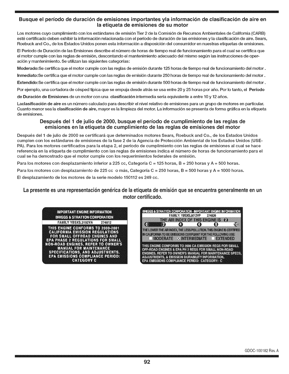
Busque el periodo de duraci6n de emisiones importantes yla informaci6n de clasificaci6n de aire en
la etiqueta de emisiones de su motor
Los motores cuyo cumpiimiento con los estAndares de emisi6n Tier 2 de la Comisi6n de Recursos Ambientales de California (CARB)
est6 certificado deben exhibir la informaci6n relacionada con el perJodo de duraci6n de las emisiones y la clasificaci6n de aire. Sears,
Roebuck and Co., de los Estados Unidos ponen esta informaci6n a disposici6n deJconsumidor en nuestras etiquetas de emisiones.
El Periodo de Duraci6n de las Emisiones describe el nQmero de horas de tiempo real de funcionamiento para el cual se certifica que
el motor cumple con las reglas de emisi6n, descontando el mantenimiento adecuado deJ mismo segQn las instrucciones de oper-
aci6n y mantenimiento. Se utilizan las siguientes categorias:
Moderado:Se certifica que el motor cumpie con las reglas de emisi6n durante 125 horas de tiempo real de funcionamiento deJmotor.
Inmediato:Se certifica que el motor cumple con las reglas de emisi6n durante 250 horas de tiempo real de funcionamiento deJ motor.
Extendido:Se certifica que el motor cumple con las reglas de emisi6n durante 500 horas de tiempo real de funcionamiento deJmotor.
Por ejemplo, una cortadora de c6sped tJpica que se empuja desde atrAs se usa entre 20 y 25 horas por afio. Por Io tanto, el Periodo
de Duraci6n de Emisiones de un motor con una clasificaci6n intermedia seria equivalente a entre 10 y 12 afios.
Laciasificaci6n de aJre es un nQmero calculado para describir eJnivel reiativo de emisiones para un grupo de motores en particular.
Cuanto menor sea Jaclasificaci6n de aire, mayor es JaJimpieza deJmotor. La informaci6n se presenta de forma gr&fica en Jaetiqueta
de emisiones.
Despu_s del 1 de julio de 2000, busque el periodo de cumplimiento de las reglas de
emisiones en la etiqueta de cumplimiento de las reglas de emisiones del motor
Despu_s deJ 1 de julio de 2000 se certificar_, que determinados motores Sears, Roebuck and Co., de los Estados Unidos
cumpien con los estAndares de emisiones de la fase 2 de la Agencia de Protecci6n Ambiental de los Estados Unidos (USE-
PA). Para los motores certificados para la etapa 2, el periodo de cumpiimiento con las reglas de emisiones al cual se hace
referencia en la etiqueta de cumpiimiento con las reglas de emisiones indica el nQmero de horas de funcionamiento para el
cuaJ se ha demostrado que el motor cumpie con los requerimientos federales de emisi6n.
Para los motores con desplazamiento inferior a 225 cc, Categoria C = 125 horas, B = 250 horas y A = 500 horas.
Para los motores con desplazamiento de 225 cc o mAs, Categoria C = 250 horas, B = 500 horas y A = 1000 horas.
El despiazamiento de los motores de la serie modelo 150112 es 249 cc.
La presente es una representaci6n gen_rica de la etiqueta de emisi6n que se encuentra generaimente en un
motor certificado.
FAMILYYBSXS.3192VA 274812
GDOC-100182Rev.A
92
Felicitacionesporhaberrealizadounaadquisici6ninteligente.El
productoCraftsman®quehaadquiridoest&diseSadoy fabricado
parabrindarmuchosaSosdefuncionamientoconfiable.Perocomo
todoslosproductosa vecespuederequerirde reparaciones.Esen
ese momentocuandoel disponerde unAcuerdode protecci6npara
reparacionesle puedeahorrardineroy problemas.
Acontinuaci6nsedetallanlos puntosincluidosen elAcuerdo:
•Servicio experto prestadopornuestros10,000especialistasen
reparacionesprofesionales
•Servicio ilimitadosincargoparalaspiezasy la manodeobraen
todaslas reparacionescubiertas
•Reemplazodel productohasta1500d61aressi no es posible
repararelproductocubierto
• Descuentode 10%del precionormaldel servicioy delas piezas
relacionadascon el mismoquenoest_ncubiertasporel acuerdo;
adem&s,10%del precionormalde laverificaci6nde manten-
imientopreventivo
• Ayudar_pidapot tel_fono -Io IlamarnosResoluci6nR_pida-el
apoyotelef6nicode unChamuscaal representante.Pienseen
nosotroscomoel manual"de undue_ohablador."
Unavezadquiridoel Acuerdo,puedeprogramarelserviciocon
tan s61orealizarunaIlamadatelef6nica.PuedeIlamarencualquier
momentodeldia o dela nocheo programarun servicioen linea.
ElAcuerdode Protecci6nde Reparaci6nes unacomprasin riesgo.
Si ustedanulaporalgunaraz6nduranteel periodode garanfiade
producto,proporcionaremosun reembolsoIleno.O, un reembolso
prorrateadoen cualquiermomentodespu_sdelperiodode garantia
de productoexpira,iAdquieraboysu acuerdode protecci6npara
reparaciones!
Se aplican determinadas limitacionesy exclusiones.Paraobtener
informaci6nadicionaly preciosen los Estados UnidosIlameal
1-800-827-6655.
El*Coverageen Canad_variaen algunosarticulos.Paradetalles
Ilenosla IlamadaChamuscaCanad_en 1-800-361-6665.
Servicio de instalaci6nde Sears
Si deseasolicitarla instalaci6nprofesionalde Searsde aparatos
dom_sticos,dispositivosparaabrirportones,calentadoresde agua
y otrosarficulosdom_sticosimportantes,en los EstadosUnidoso
Canad_Ilameal 1-800-4-MY-HOME®.
93

94

95

Your Home
For expert troubleshooting and home solutions advice:
www.managemyhome.com
For repair - in your home - of all major brand appliances,
lawn and garden equipment, or heating and cooling systems,
no matter who made it, no matter who sold it!
For the replacement parts, accessories and
owner's manuals that you need to do-it-yourself.
For Sears professional installation of home appliances
and items like garage door openers and water heaters.
1-800-4-MY-HOME ®(1-800-469-4663)
Call anytime, day or night (U.S.A. and Canada)
www.sears.com www.sears.ca
Our Home
For repair of carry-in items like vacuums, lawn equipment,
and electronics, call anytime for the location of your nearest
Sears Parts & Repair Service Center
1-800-488-1222 (U.S.A.) 1-800-469-4663 (Canada)
www.sears.com www.sears.ca
To purchase a protection agreement on a product serviced by Sears:
1-800-827-6655 (U.S.A.) 1-800-361-6665 (Canada)
Para pedir servicio de reparaci6n
a domicilio, y para ordenar piezas:
1-888-SU-HOGAR ®
(1-888-784-6427)
Au Canada pour service en fran£ais:
1-800-LE-FOYER M°
(1-800-533-6937)
www.sears.ca
® Registered Trademark /TMTrademark /SM Service Mark of Sears Brands, LLC
SM
® Marca Registrada /TMMarca de F&brica /Marca de Servicio de Sears Brands, LLC
MCMarque de commerce /MDMarque depos6e de Sears Brands, LLC © Sears Brands, LLC
