MTD 19A70004 User Manual TWIN REAR BAGGER Manuals And Guides 1203448L
User Manual: MTD 19A70004 19A70004 MTD TWIN REAR BAGGER - Manuals and Guides View the owners manual for your MTD TWIN REAR BAGGER #19A70004. Home:Lawn & Garden Parts:MTD Parts:MTD TWIN REAR BAGGER Manual
Open the PDF directly: View PDF ![]() .
.
Page Count: 20

L
Twin Rear Bagger- Model 19AT0004OEM
MTD LLC, P.O. BOX 361131 CLEVELAND, OHiO 44136-0019
PrintedIn USA FormNo.769-04697C
(March24,2010)
ToTheOwner
ThankYou
Thank you for purchasing a bagging attachment manufactured
by MTD LLC. It was carefully engineered to provide excellent
performance when properly operated and maintained.
Please read this entire manual prior to operating the equipment.
It instructs you how to safely and easily set up, operate and
maintain this attachment. Please be sure that you, and any
other persons who will operate the machine, carefully follow the
recommended safety practices at all times. Failure to do so could
result in personal injury or property damage.
All information in this manual is relative to the most recent
product information available at the time of printing. Review this
manual frequently to familiarize yourself with the attachment,
its features and operation. Please be aware that this Operator's
Manual may cover a range of product specifications for various
models. Characteristics and features discussed and/or illustrated
in this manual may not be applicable to all models. MTD LLC
reserves the right to change product specifications, designs and
equipment without notice and without incurring obligation.
1
If you have any problems or questions concerning this
attachment, phone your local authorized MTD service dealer
or contact us directly. MTD's Customer Support telephone
numbers, website address and mailing address can be found on
this page. We want to ensure your complete satisfaction at all
times.
Throughout this manual, all references to right and left side of the
machine are observed from the operating position
Tableof Contents
Safe Operation Practices ........................................ 3
Carton Contents &Hardware Packs ...................... 6
Assembly &Installation .......................................... 8
Operation ................................................................ 16
Parts List .................................................................. 18
Warranty .................................................. Back Cover
Record Product information
Before setting up and operating your new equipment, please
locate the model plate on the equipment and record the
information in the provided area to the right. You can locate the
model plate by looking at the topside of the bagger cover. This
information will be necessary, should you seek technical support
via our web site, Customer Support Department, or with a local
authorized service dealer.
MODEL NUMBER
DDDDDDDDDDD
SERIAL NUMBER
D[3D[3D[3D[3D[3D
CustomerSupport
Please do NOT return the machine to the retailer or dealer without first contacting our Customer Support Department.
If you have difficulty assembling this product or have any questions regarding the controls, operation, or maintenance of
this machine, you can seek help from the experts. Choose from the options below:
0 Visit us on the web at www.mtdproducts.com
0 Call a Customer Support Representative at (800) 800-7310 or (330) 220-4683
0 Write us at MTD LLC •RO. Box 361131 •Cleveland, OH •44136-0019

ImportantSafeOperationPractices 2
WARNING! This symbol points out important safety instructions which, if not followed,
could endanger the personal safety and/or property of yourself and others. Read and follow
all instructions in this manual before attempting to operate this machine. Failure to comply
with these instructions may result in personal injury.
When you see this symbol. HEED ITS WARNING!
DANGERI This attachment was built to be used according to the safe operation practices in
this manual. Carelessness or error on the part of the operator can result in serious injury.
Mowers are capable of amputating hands and feet and throwing objects. Failure to observe
the following safety instructions as well as the instructions provided with your mower, could
result in serious injury or death.
General Operation
1. Read, understand, and follow all instructions on your
equipment and in their manuals before attempting to
assemble and operate. Keep this manual in a safe place for
future and regular reference and for ordering replacement
parts.
2. To help avoid blade contact or a thrown object injury, keep
bystanders, helpers, children and pets at least 75 feet from
the mower while it is in operation. Stop machine if anyone
enters the area.
3. Thoroughly inspect the area where the equipment is to be
used. Remove all stones, sticks, wire, bones, toys, and other
foreign objects which could be picked up and thrown by
the blade(s). Thrown objects can cause serious personal
injury.
4. Always wear safety glasses or safety goggles during
operation and while performing an adjustment or repair
to protect your eyes. Thrown objects which ricochet can
cause serious injury to the eyes.
5. Do not operate the mower without the discharge cover
or entire grass catcher in its proper place. A missing
or damaged discharge cover or grass bag attachment
component may result in thrown objects or blade contact
injuries.
6. Do not put hands or feet near rotating parts or under the
cutting deck. Contact with the blade(s) can amputate
hands and feet.
7. Shut off mower's engine and wait for blades to come to
a complete stop before unclogging mower's discharge
opening or bagger parts.
8. Slow down before turning. Operate the machine smoothly.
Avoid erratic operation and excessive speed. Be aware
that a grass catcher attachment can affect the handling
characteristics of your mower.
9. Disengage blade(s), set parking brake, stop engine and wait
until the blade(s) come to a complete stop before opening
bagger attachment's top cover, removing grass catcher,
emptying grass, unclogging chute, removing any grass or
debris, or making any adjustments.
10. Never leave a running machine unattended. Always turn
off blade(s), place transmission in neutral, set parking
brake, stop engine and remove key before dismounting.
11. Your machine is designed to cut normal residential grass of
a height no more than 10". Do not attempt to mow through
unusually tall, dry grass (e.g., pasture) or piles of dry leaves.
Dry grass or leaves may contact the engine exhaust and/
or build up on the mower deck presenting a potential fire
hazard.
12. If situations occur which are not covered in this manual, use
care and good judgment. Contact your customer service
representative for assistance.
SlopeOperation
Slopes are a major factor related to loss of control and tip-over
accidents which can result in severe injury or death. Attachments
can also affect the stability of the machine. All slopes require
extra caution.
For your safety, use the slope gauge included as part of this
manual to estimate the angle of slopes before operating this
machine on a sloped or hilly area. If the slope is greater than 10
degrees as shown on the slope gauge, do not operate the mower
with the grass bag attachment installed on that area or serious
injury could result.
Do:
1. Mow up and down slopes, not across. Exercise extreme
caution when changing direction on slopes.
2. Watch for holes, ruts, bumps, rocks, or other hidden
objects. Uneven terrain could overturn the machine. Tall
grass can hide obstacles.
3. Useslowspeed.Choosealowenoughspeedsettingso
thatyouwillnothavetostoporshiftwhileontheslope.
Tiresmaylosetractiononslopeseventhoughthebrakes
arefunctioningproperly.Alwayskeepmachineingear
whengoingdownslopestotakeadvantageofengine
brakingaction.
4. Followthemanufacturer'srecommendationsforwheel
weightsorcounterweightstoimprovestability.
5. Keepallmovementontheslopesslowandgradual.Do
notmakesuddenchangesinspeedordirection.Rapid
engagementorbrakingcouldcausethefrontofthe
machinetoliftandrapidlyflipoverbackwardswhichcould
causeseriousinjury.
6. Avoidstartingorstoppingonaslope.Iftireslosetraction,
disengagetheblade(s)andproceedslowlystraightdown
theslope.
D0 Not:
1. Do not turn on slopes unless necessary; then, turn slowly
and gradually downhill, if possible.
2. Do not mow near drop-offs, ditches or embankments. The
mower could suddenly turn over if a wheel is over the edge
of a cliff, ditch, or if an edge caves in.
3. Do not try to stabilize the machine by putting your foot on
the ground.
4. Do not use a grass catcher on steep slopes.
5. Do not mow on wet grass. Reduced traction could cause
sliding.
GeneralService
1. Before cleaning, repairing, or inspecting, make certain the
blade(s) and all moving parts have stopped. Disconnect the
spark plug wire and ground against the engine to prevent
unintended starting.
2. Keep all nuts, bolts, and screws tight to be sure the
equipment is in safe working condition.
3. Never tamper with your mower's safety interlock system
or other safety devices. Check their proper operation
regularly.
4. Never attempt to make adjustments or repairs while the
mower's engine is running.
5. Grass catcher components and the discharge cover are
subject to wear and damage which could expose moving
parts or allow objects to be thrown. For safety protection,
frequently check components and replace immediately
with original equipment manufacturer's (O.E.M.) parts only,
listed in this manual. Use of parts which do not meet the
original equipment specifications may lead to improper
performance and compromise safety!
6. Maintain or replace safety and instruction labels, as
necessary.
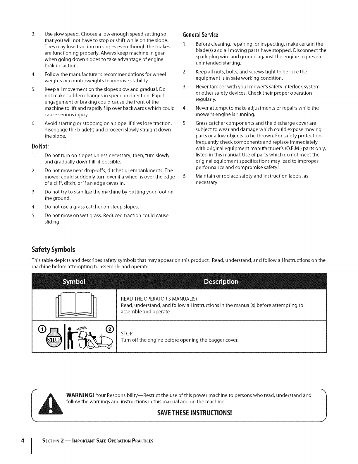
Safety Symbols
This table depicts and describes safety symbols that may appear on this product. Read, understand, and follow all instructions on the
machine before attempting to assemble and operate.
READ THE OPERATOR'S MANUAL(S)
Read, understand, and follow all instructions in the manual(s) before attempting to
assemble and operate
STOP
Turn offthe engine before opening the bagger cover.
I l_ll WARNING! Your Responsibility--Restrict the use of this power machine to persons who read, understand and
%
follow the warnings and instructions in this manual and on the machine.
SAVETHESEINSTRUCTIONS!
4 I SECTION 2 -- IMPORTANT SAFE OPERATION PRACTICES
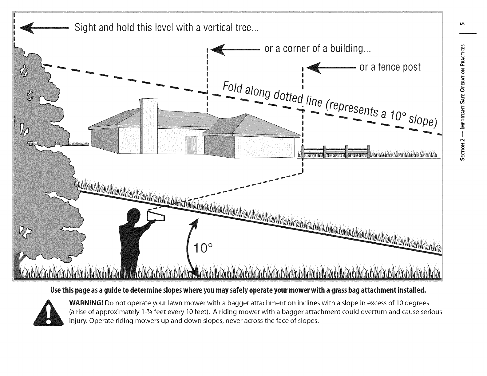
Sight andholdthis level with a vertical tree...
!
|
|
|
|
|
|
|
or a corner of a building...
_ or a fence post
|
,
d along d " '
Otted_.._iine_(represents
,a 10oslope)
|
I
|
10 °
I-
v
Z
0
0
!--
Z
Q.
i
¢N
Z
£
In
Usethis page asaguide to determine slopeswhere you may safely operate your mower with a grassbag attachment installed.
WARNING! Do not operate your lawn mower with a bagger attachment on inclines with a slope in excess of 10 degrees
(a rise of approximately 1-3,4feet every 10 feet). A riding mower with a bagger attachment could overturn and cause serious
injury. Operate riding mowers up and down slopes, never across the face of slopes.
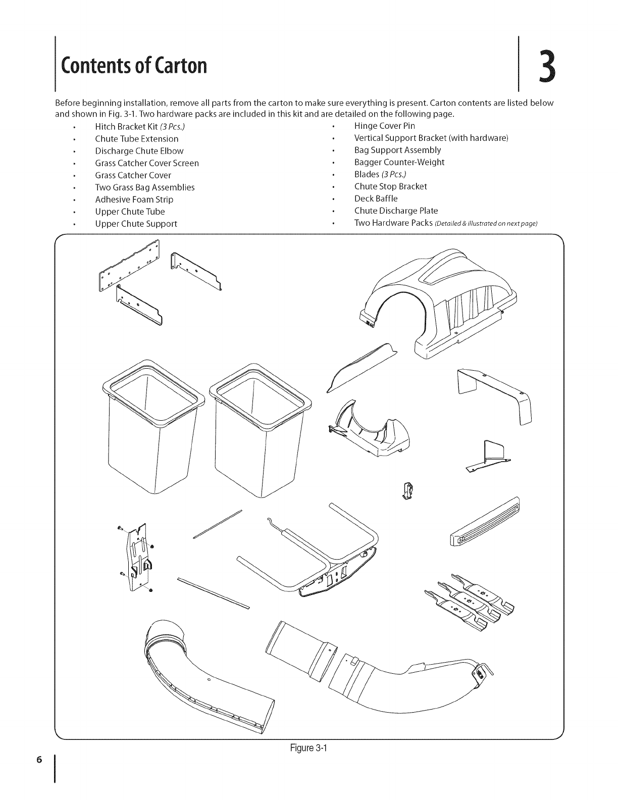
Contentsof Carton 3
Before beginning installation, remove all parts from the carton to make sure everything is present. Carton contents are listed below
and shown in Fig. 3-1. Two hardware packs are included in this kit and are detailed on the following page.
Hitch Bracket Kit (3 Pcs.)
Chute Tube Extension
Discharge Chute Elbow
Grass Catcher Cover Screen
Grass Catcher Cover
Two Grass Bag Assemblies
Adhesive Foam Strip
Upper Chute Tube
Upper Chute Support
Hinge Cover Pin
Vertical Support Bracket (with hardware)
Bag Support Assembly
Bagger Counter-Weight
Blades (3 Pcs.)
Chute Stop Bracket
Deck Baffle
Chute Discharge Plate
Two Hardware Packs (Detailed&illustratedon nextpage)
6IFigure3-1
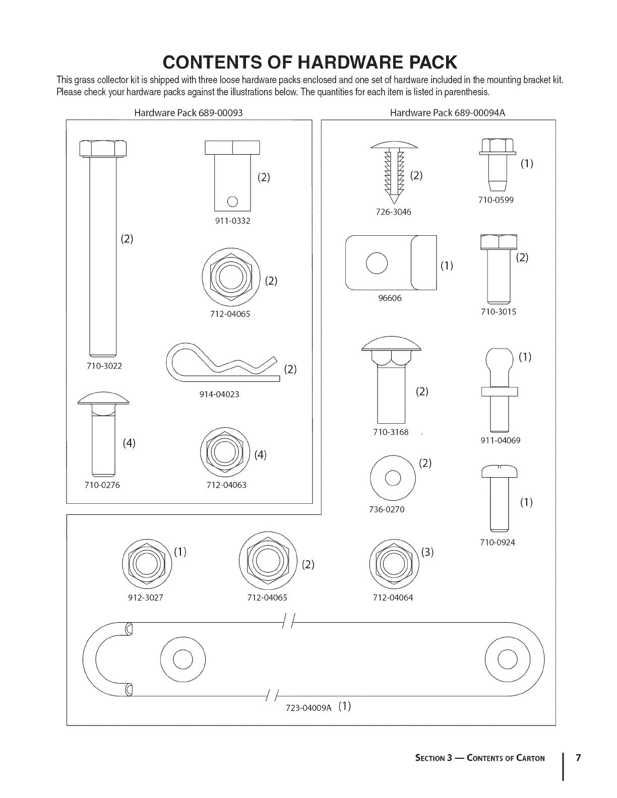
CONTENTS OF HARDWARE PACK
Thisgrasscollectorkit is shippedwiththree loosehardwarepacksenclosedandonesetof hardwareincludedinthe mountingbracketkit.
Pleasecheckyourhardwarepacksagainsttheillustrationsbelow.Thequantitiesfor eachitemis listedinparenthesis.
Hardware Pack 689-00093 Hardware Pack 689-00094A
2)
710-3022
_](4)
710-0276
I t I
O I 2)
911-0332
(2)
712-04065
914-04023
(4/
712-04063
(2)
(1)
(2)
710-0599
726-3046
96606
(1)
[_(2)
710-3015
E_(1 )
(2)
710-3.168
911-04069
912-3027
(1)
(2)
712-04065
(2)
736-0270 (I)
//
//
723-04009A (1)
(3)
712-o4o64
710-0924
SECTION3-- CONTENTS OF CARTON 7
Assembly& installation 3
NOTE: References to left, right, front and rear of the tractor are
from the operator's position, unless otherwise stated.
Before assembly, place the tractor on a firm, level surface,
disengage the PTO, stop the tractor engine and set the
parking brake.
For convenience, pivot the seat forward and leave it in
that position until the grass collector is fully mounted and
assembled.
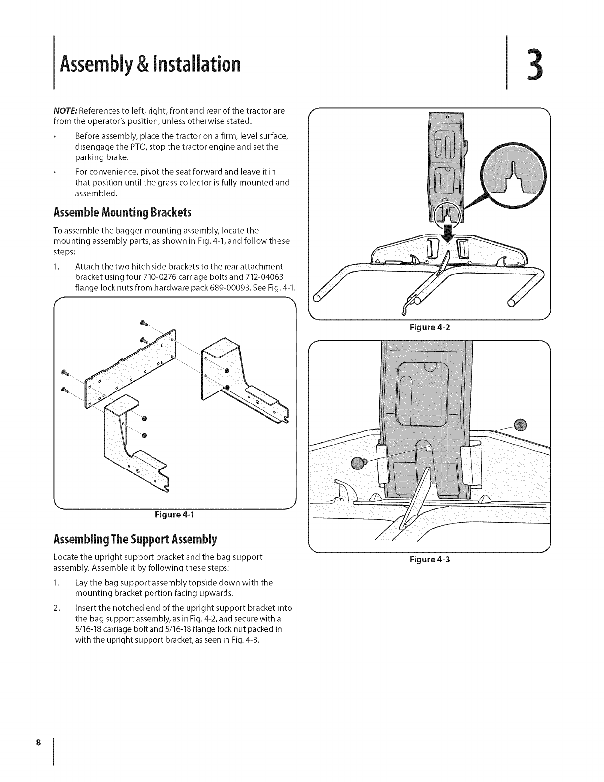
AssembleMounting 8rackets
To assemble the bagger mounting assembly, locate the
mounting assembly parts, as shown in Fig. 4-1, and follow these
steps:
1. Attach the two hitch side brackets to the rear attachment
bracket using four 710-0276 carriage bolts and 712-04063
flange lock nuts from hardware pack 689-00093. See Fig. 4-1.
Figure 4-1
AssemblingTheSupport Assembly
Locate the upright support bracket and the bag support
assembly. Assemble it by following these steps:
1. Lay the bag support assembly topside down with the
mounting bracket portion facing upwards.
2. Insert the notched end of the upright support bracket into
the bag support assembly, as in Fig. 4-2, and secure with a
5/16-18 carriage bolt and 5/16-18 flange lock nut packed in
with the upright support bracket, as seen in Fig. 4-3.
F
Figure 4=2
Figure 4=3
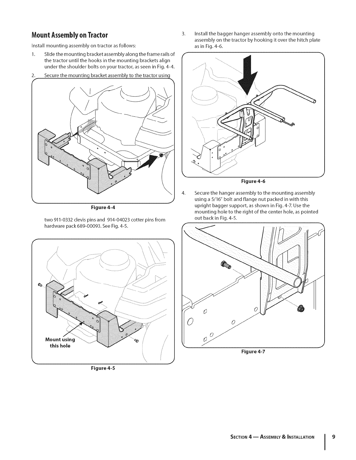
MountAssemblyonTractor
Install mounting assembly on tractor as follows:
1. Slide the mounting bracket assembly along the frame rails of
the tractor until the hooks in the mounting brackets align
under the shoulder bolts on your tractor, as seen in Fig. 4-4.
2. Secure the mounting bracket assembly to the tractor usin(
Figure 4-4
two 911-0332 clevis pins and 914-04023 cotter pins from
hardware pack 689-00093. See Fig. 4-5.
3_
4_
Install the bagger hanger assembly onto the mounting
assembly on the tractor by hooking it over the hitch plate
as in Fig. 4-6.
Figure 4-6
Secure the hanger assembly to the mounting assembly
using a 5/16" bolt and flange nut packed in with this
upright bagger support, as shown in Fig. 4-7. Use the
mounting hole to the right of the center hole, as pointed
out back in Fig. 4-5.
Mount using
this hole
Figure 4-5
/
Figure 4-7
SECTION 4 -- ASSEMBLY& INSTALLATION 9
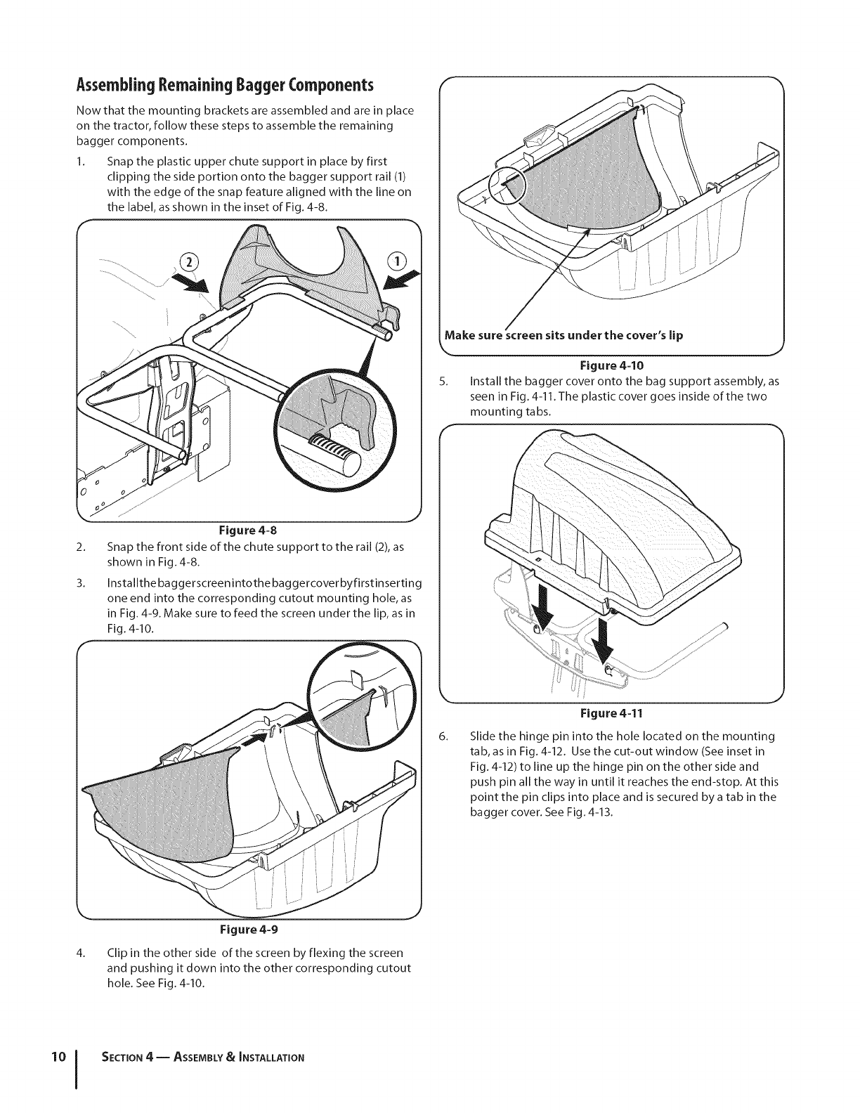
AssemblingRemainingBaggerComponents
Now that the mounting brackets are assembled and are in place
on the tractor, follow these steps to assemble the remaining
bagger components.
1. Snap the plastic upper chute support in place by first
clipping the side portion onto the bagger support rail (1)
with the edge of the snap feature aligned with the line on
the label, as shown in the inset of Fig. 4-8.
f
Make sure screen sits under the cover's lip
k
Figure 4=10
5. Install the bagger cover onto the bag support assembly, as
seen in Fig. 4-11. The plastic cover goes inside of the two
mounting tabs.
2_
3.
Figure 4=8
Snap the front side of the chute support to the rail (2), as
shown in Fig. 4-8.
Installthe baggerscreenintothe baggercoverbyfirstinserting
one end into the corresponding cutout mounting hole, as
in Fig. 4-9. Make sure to feed the screen under the lip, as in
Fig. 4-10.
Figure 4=11
6_ Slide the hinge pin into the hole located on the mounting
tab, as in Fig. 4-12. Use the cut-out window (See inset in
Fig. 4-12) to line up the hinge pin on the other side and
push pin all the way in until it reaches the end-stop. At this
point the pin clips into place and is secured by a tab in the
bagger cover. See Fig. 4-13.
4_
Figure 4-9
Clip in the other side of the screen by flexing the screen
and pushing it down into the other corresponding cutout
hole. See Fig. 4-10.
SECTION 4 -- ASSEMBLY&INSTALLATION
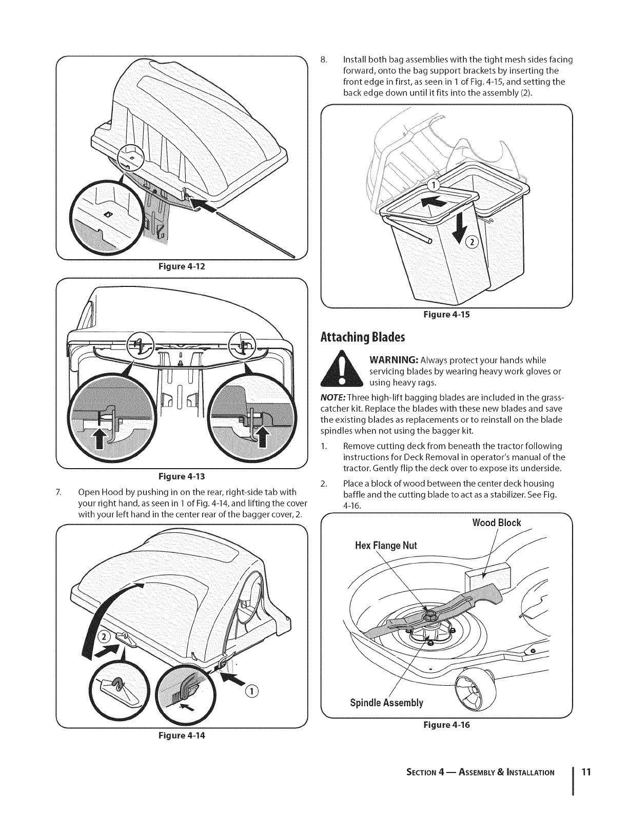
8. Install both bag assemblies with the tight mesh sides facing
forward, onto the bag support brackets by inserting the
front edge in first, as seen in 1 of Fig.4-15, and setting the
back edge down until it fits into the assembly (2).
Figure 4-12
nJ
Figure 4=13
7. Open Hood by pushing in on the rear, right-side tab with
your right hand, as seen in 1 of Fig. 4-14, and lifting the cover
with your left hand in the center rear of the bagger cover, 2.
Figure 4=14
Figure 4=15
AttachingBlades
d_lk WARNING: Always protect your hands while
servicing blades by wearing heavy work gloves or
using heavy rags.
NOTE:Three high-lift bagging blades are included in the grass-
catcher kit. Replace the blades with these new blades and save
the existing blades as replacements or to reinstall on the blade
spindles when not using the bagger kit.
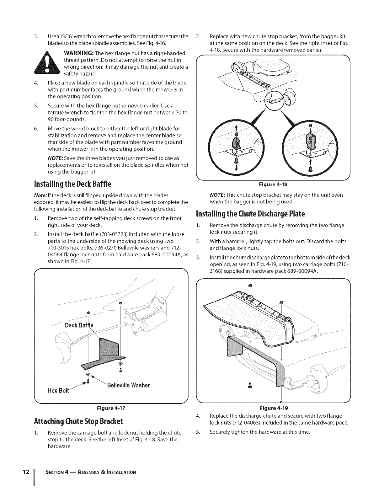
1. Remove cutting deck from beneath the tractor following
instructions for Deck Removal in operator's manual of the
tractor. Gently flip the deck over to expose its underside.
2. Place a block of wood between the center deck housing
baffle and the cutting blade to act as a stabilizer. See Fig.
4-16.
f- -,_
Wood Block
HexRange Nut
SpindleAssembly
Figure 4=16
SECTION 4 -- ASSEMBLY&INSTALLATION 11
3_ Usea 15/16"wrenchto removethe hexfla nge nutthatsecuresthe
blades to the blade spindle assemblies. See Fig. 4-16.
i_ WARNING: The hex flange nut has a right-handed
thread pattern. Do not attempt to force the nut in
wrong direction; it may damage the nut and create a
safety hazard.
4. Placea new blade on each spindle so that side of the blade
with part number faces the ground when the mower is in
the operating position.
5. Secure with the hex flange nut removed earlier. Usea
torque wrench to tighten the hex flange nut between 70 to
90 foot-pounds.
6. Move the wood block to either the left or right blade for
stabilization and remove and replace the center blade so
that side of the blade with part number faces the ground
when the mower is in the operating position.
NOTE:Save the three blades you just removed to use as
replacements or to reinstall on the blade spindles when not
using the bagger kit.
Installingthe DeckBaffle
Note: If the deck isstill flipped upside down with the blades
exposed, it may be easiest to flip the deck back over to complete the
following installation of the deck baffle and chute stop bracket.
1. Remove two of the self-tapping deck screws on the front
right side of your deck.
2. Install the deck baffle (703-05783) included with the loose
parts to the underside of the mowing deck using two
710-3015 hex bolts, 736-0270 Belleville washers and 712-
04064 flange lock nuts from hardware pack 689-00094A, as
shown in Fig. 4-17.
F
2_
F
Replace with new chute stop bracket, from the bagger kit,
at the same position on the deck. Seethe right Inset of Fig.
4-18. Secure with the hardware removed earlier.
Figure 448
NOTE:This chute stop bracket may stay on the unit even
when the bagger is not being used.
Installing the ChuteDischargePlate
1. Remove the discharge chute by removing the two flange
lock nuts securing it.
2. With a hammer, lightly tap the bolts out. Discard the bolts
and flange lock nuts.
3. Installthechutedischarge piatetothe bottom sideofthedeck
opening, as seen in Fig. 4-19, using two carriage bolts (710-
3168) supplied in hardware pack 689-00094A.
f
....................Deck Baffle
I
Hex Bolt "_ Belleville Washer
Figure 447
AttachingChuteStopBracket
1. Remove the carriage bolt and lock nut holding the chute
stop to the deck. Seethe left Inset of Fig.4-18. Savethe
hardware.
Figure 4=19
4. Replace the discharge chute and secure with two flange
lock nuts (712-04065) included in the same hardware pack.
5. Securely tighten the hardware at this time.
12 I SECTION 4 -- ASSEMBLY& INSTALLATION
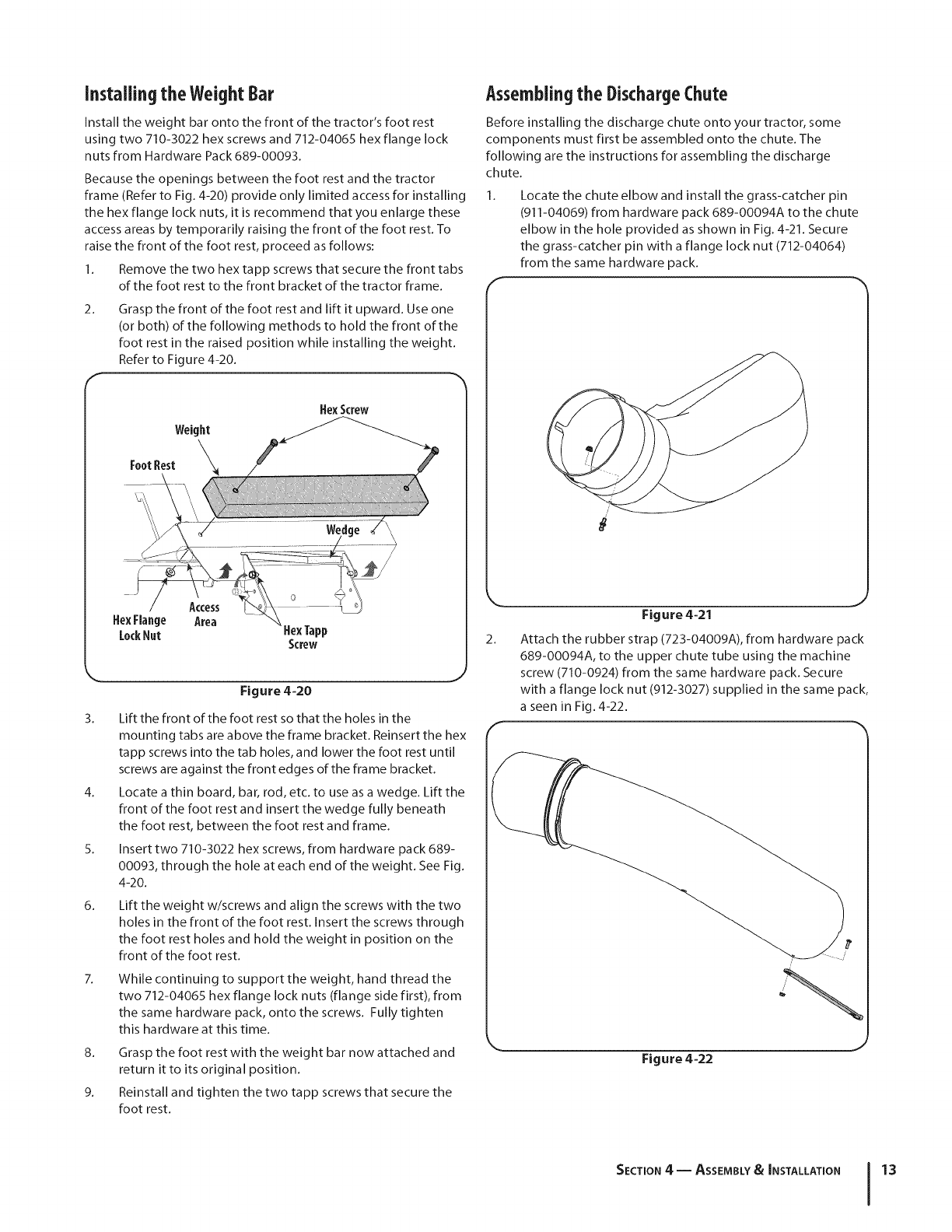
Installingthe WeightBar
Install the weight bar onto the front of the tractor's foot rest
using two 710-3022 hex screws and 712-04065 hex flange lock
nuts from Hardware Pack 689-00093.
Because the openings between the foot rest and the tractor
frame (Refer to Fig. 4-20) provide only limited access for installing
the hex flange lock nuts, it is recommend that you enlarge these
access areas by temporarily raising the front of the foot rest. To
raise the front of the foot rest, proceed as follows:
1. Remove the two hex tapp screws that secure the front tabs
of the foot rest to the front bracket of the tractor frame.
2. Grasp the front of the foot rest and lift it upward. Use one
(or both) of the following methods to hold the front of the
foot rest in the raised position while installing the weight.
Refer to Figure 4-20.
HexScrew
3.
4.
5.
6.
Access
Area
Figure 4=20
Lift the front of the foot rest so that the holes in the
mounting tabs are above the frame bracket. Reinsert the hex
tapp screws into the tab holes, and lower the foot rest until
screws are against the front edges of the frame bracket.
Locate a thin board, bar, rod, etc. to use as a wedge. Lift the
front of the foot rest and insert the wedge fully beneath
the foot rest, between the foot rest and frame.
Insert two 710-3022 hex screws, from hardware pack 689-
00093, through the hole at each end of the weight. See Fig.
4-20.
Lift the weight w/screws and align the screws with the two
holes in the front of the foot rest. Insert the screws through
the foot rest holes and hold the weight in position on the
front of the foot rest.
While continuing to support the weight, hand thread the
two 712-04065 hex flange lock nuts (flange side first), from
the same hardware pack, onto the screws. Fully tighten
this hardware at this time.
8. Grasp the foot rest with the weight bar now attached and
return it to its original position.
9. Reinstall and tighten the two tapp screws that secure the
foot rest.
Assemblingthe DischargeChute
Before installing the discharge chute onto your tractor, some
components must first be assembled onto the chute. The
following are the instructions for assembling the discharge
chute.
Locate the chute elbow and install the grass-catcher pin
(911-04069) from hardware pack 689-00094A to the chute
elbow in the hole provided as shown in Fig. 4-21. Secure
the grass-catcher pin with a flange lock nut (712-04064)
from the same hardware pack.
/
Figure 4-21
2.
r
Attach the rubber strap (723-04009A), from hardware pack
689-00094A, to the upper chute tube using the machine
screw (710-0924) from the same hardware pack. Secure
with a flange lock nut (912-3027) supplied in the same pack,
a seen in Fig. 4-22.
k. Figure 4=22
,J
SECTION 4 -- ASSEMBLY&INSTALLATION 13
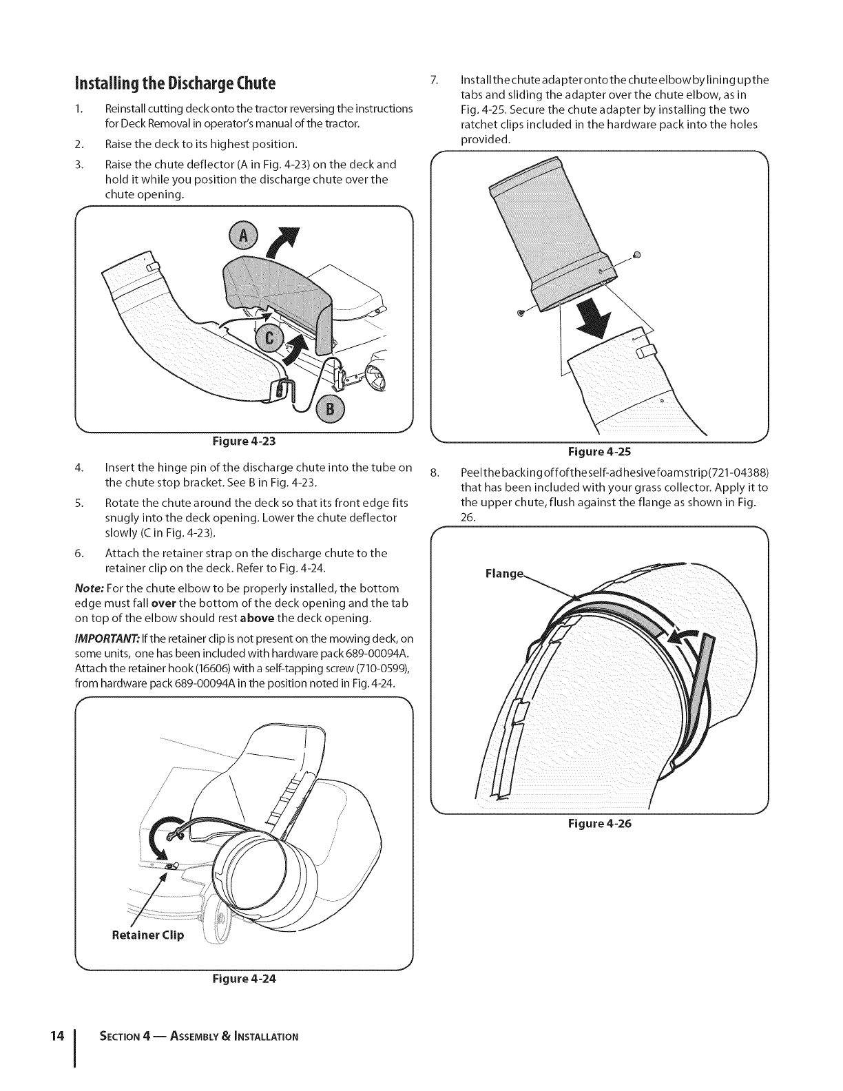
Installingthe DischargeChute
1. Reinstall cutting deck onto the tractor reversing the instructions
for Deck Removal in operator's manual of the tractor.
2. Raise the deck to its highest position.
3. Raise the chute deflector (A in Fig. 4-23) on the deck and
hold it while you position the discharge chute over the
chute opening.
7_
F
Installthe chute adapter ontothe chute elbow by lining upthe
tabs and sliding the adapter over the chute elbow, as in
Fig. 4-25. Secure the chute adapter by installing the two
ratchet clips included in the hardware pack into the holes
provided.
Figure 4=23
4. Insert the hinge pin of the discharge chute into the tube on
the chute stop bracket. See B in Fig. 4-23.
5. Rotate the chute a round the deck so that its front edge fits
snugly into the deck opening. Lower the chute deflector
slowly (C in Fig. 4-23).
6. Attach the retainer strap on the discharge chute to the
retainer clip on the deck. Refer to Fig. 4-24.
Note: For the chute elbow to be properly installed, the bottom
edge must fall over the bottom of the deck opening and the tab
on top of the elbow should rest above the deck opening.
IMPORTANT: If the retainer clip is not present on the mowing deck, on
some units, one has been included with hardware pack 689-00094A.
Attach the retainer hook (16606) with a self-tapping screw (710-0599),
from hardware pack 689-00094A in the position noted in Fig. 4-24.
Figure 4=25
8. Peelthe backing offoftheself-ad hesivefoam strip(721-04388)
that has been included with your grass collector. Apply it to
the upper chute, flush against the flange as shown in Fig.
26.
F
Figure 4-26
SECTION 4 -- ASSEMBLY&INSTALLATION
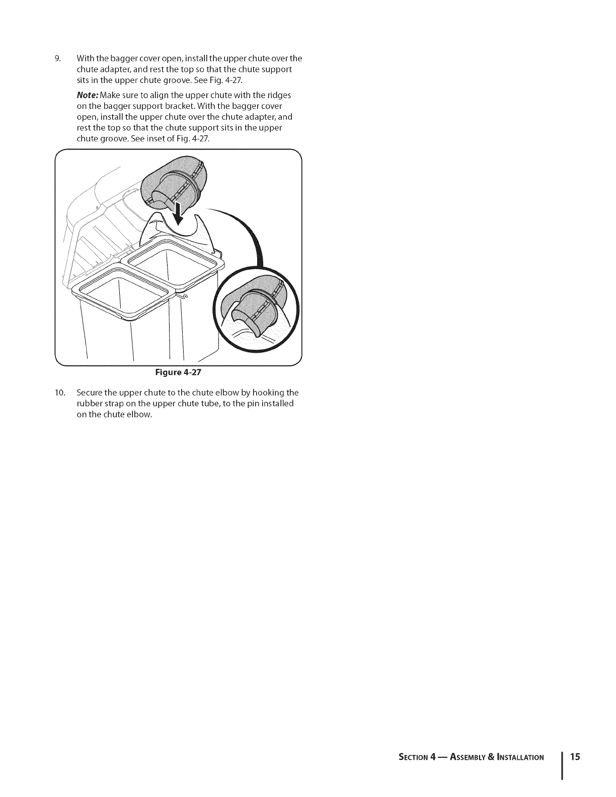
9_ With the bagger cover open, install the upper chute over the
chute adapter, and rest the top so that the chute support
sits in the upper chute groove. See Fig. 4-27.
Note:Make sure to align the upper chute with the ridges
on the bagger support bracket. With the bagger cover
open, install the upper chute over the chute adapter, and
rest the top so that the chute support sits in the upper
chute groove. See inset of Fig. 4-27.
10.
Figure 4-27
Secure the upper chute to the chute elbow by hooking the
rubber strap on the upper chute tube, to the pin installed
on the chute elbow.
SECTION 4 -- ASSEMBLY&INSTALLATION 15

Operation 5
BaggerUsage
NOTE:When both grass bags are full, place the tractor on a firm,
level surface, disengage the PTO, turn the tractor engine off and
set the parking brake.
1. Pivot the seat forward.
2_ Open the grass catcher hood by pushing in on the rear,
right-side tab with your right hand, as seen in 1 of Fig. 5-1,
and lifting the cover with your left hand in the center rear of
the bagger cover, 2.
5. Empty the grass clippings at a proper disposal site, use the
handle at the bottom of each grass bag. Holding the bag
firmly, empty the contents
6. Replace grass bags, close lid, flip down seat, restart your
tractor, release parking brake and resume cutting your
grass.
3_
4.
.J
Figure 5-1
Do not remove the chute tube assembly from the tractor.
Remove the grass bags by lifting these up (1) and moving
the bags away from the bag support assembly (2). See Fig.
5-2.
/
Figure 5-2
'°1

This page intentionally left blank.
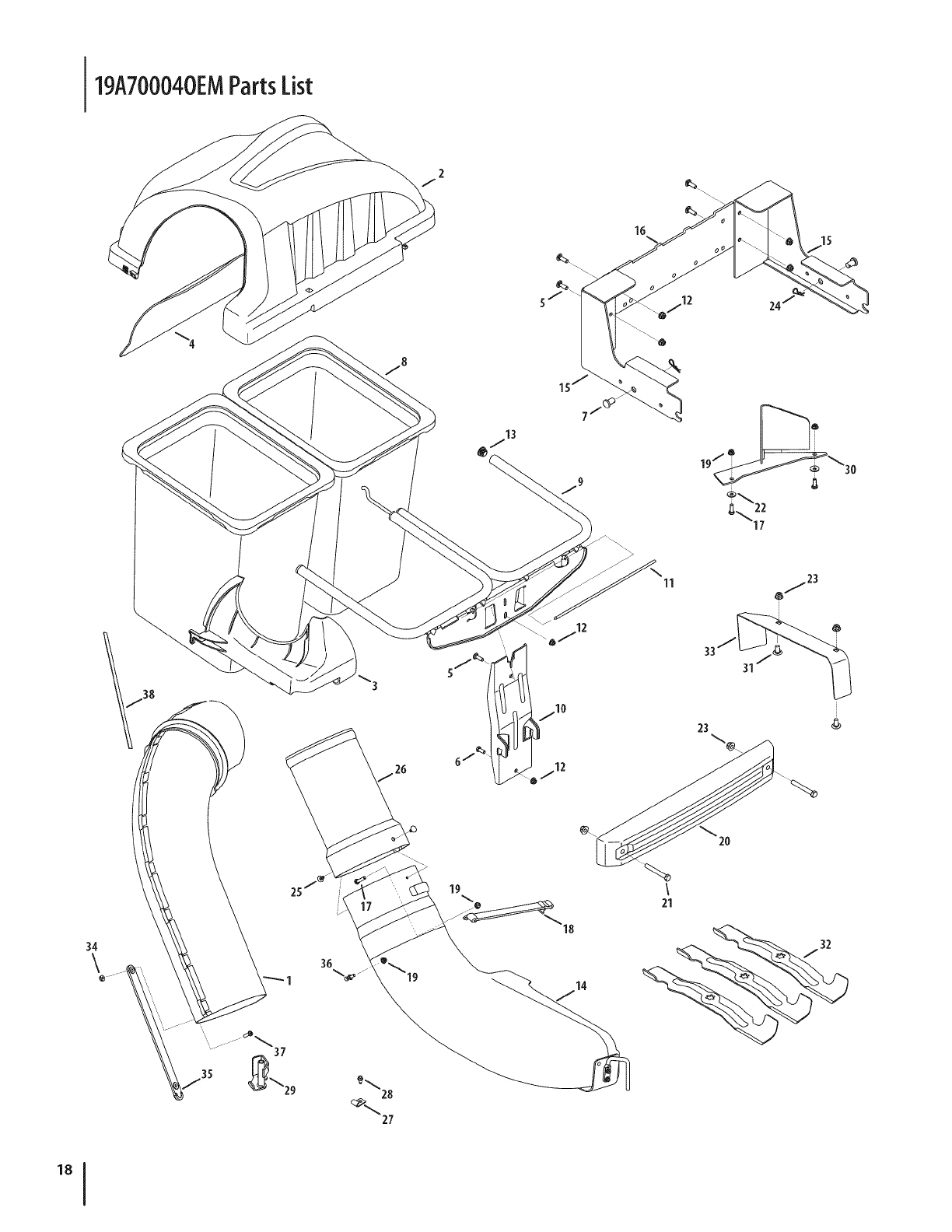
19A700040EMPartsList
24
33j
23
28
27

Ref, I
1.
2.
3.
4.
5.
6.
7.
8.
9.
10.
11.
12.
13.
14.
15.
16.
17.
18.
19.
20.
21.
22.
23.
24.
25.
26.
27.
28.
29.
30.
31.
32.
33.
34.
35.
36.
37.
38.
Part Number
631-04295A
931-04292
731-06497
731-06504
710-0276
710-3008
911-0332
964-04096
683-04461-0637
683-04519-0637
711-04988
712-04063
735-0246A
631-04300A
689-00111
783-06168-0637
710-3015
723-0476
712-04064
719-04271A
710-3022
736-0270
712-04065
914-04023
726-3046
731-06611
96606
710-0599
683-0617A-0637
703-05783-0637
710-3168
742-0405600637
783-06694-0637
912-3027
723-04009A
911-04069
710-0924
721-04388
Description
Upper Chute Assembly
Twin Bagger Cover Assembly
Upper Chute Support
Bagger Cover Screen
Carriage Screw, 5/16-18 x 1.00"
Hex Head Screw, 5/16-18 x .75"
Clevis Pin, .50" Dia.
Grass-bag Assembly
Twin Bag Support Assembly
Vertical Support Bracket
Cover Hinge Pin
Flange Lock Nut, 5/16-18
End Plug
Discharge Chute Elbow
RZT Hitch Bracket Kit (RH & LH)
Universal Cross Bracket
Hex Head Screw, 1/4 - 20 x .75
Chute Strap
Flange Lock Nut, 1/4 - 20
Bagger Weight
Hex Head Screw, 3/8- 16 x 2.75
Belleville Washer
Flange Lock Nut, 3/8 - 16
Cotter Pin, .080 x 1.5625 Internal
Ratchet Clip, .250
Bagger Chute Adapter, 8 x 13.5
Retainer Hook Bracket
Self-Tap Screw, 1/4-20 x .500
Chute Stop Bracket
Deck Baffle, 50"
Carriage Bolt, 3/8-16 x 1.00
Bagging Blade, 17.90 Lg. Star
Chute Discharge Plate
Flange Lock Nut, 1/4-20
Chute Strap
Grass-catcher Pin
Machine Screw, 1/4-20
Adhesive Strip
PARTSLIST 19

MANUFACTURER'S LiMiTED WARRANTY FOR
The limited warranty set forth below is given by MTD LLC with
respect to new merchandise purchased and used in the United States
and/or its territories and possessions, and by MTD Products Limited
with respect to new merchandise purchased and used in Canadaand/
or its territories and possessions (either entity respectively, "MTD").
"MTD" warrants this product (excluding its Normal WearParts and
Attachments as described below) against defects in material and
workmanship for a period of one (1) year commencing on the date
of original purchase and will, at its option, repair or replace, free of
charge, any part found to be defective in materials or workmanship.
This limited warranty shall only apply if this product has been
operated and maintained in accordance with the Operator's Manual
furnished with the product, and has not been subject to misuse,
abuse, commercial use, neglect, accident, improper maintenance,
alteration, vandalism, theft, fire, water, or damage because of other
peril or natural disaster. Damage resulting from the installation or use
of any part, accessory or attachment not approved by MTD for use
with the product(s) covered by this manual will void your warranty as
to any resulting damage.
Normal WearParts are warranted to befree from defects in material
and workmanship for a period of thirty (30) days from the date of
purchase. Normal wear parts include, but are not limited to items
such as: batteries, belts, blades, blade adapters, tines, grass bags,
wheels, rider deck wheels, seats, snow thrower skid shoes, friction
wheels, shave plates, auger spiral rubber and tires.
Attachments-- MTD warrants attachments for this product against
defects in material and workmanship for a period of one (1) year,
commencing on the date of the attachment's original purchase or
lease. Attachments include, but are not limited to items such as:
grass collectors and mulch kits.
HOWTO OBTAINSERVICE:Warranty service is available, WITH
PROOFOFPURCHASE,through your local authorized service dealer.
To locate the dealer in your area:
In the U.S.A.
Check your Yellow Pages, or contact MTD LLC at RO. Box 361131,
Cleveland, Ohio 44136-0019, or call 1-800-800-7310, 1-330-220-
4683 or log on to our Web site at www.mtdproducts.com.
In Canada
Contact MTD Products Limited, Kitchener, ON N2G4J1, or call 1-800-
668-1238 or log on to our Web site at www.mtdcanada.com.
This limited warranty does not provide coverage in the following
cases:
a. Log splitter pumps, valves, and cylinders havea separate one-
year warranty.
b. Routine maintenance items such as lubricants, filters, blade
sharpening, tune-ups, brake adjustments, clutch adjustments,
deck adjustments, and normal deterioration of the exterior finish
due to use or exposure.
c. Service completed by someone other than an authorized service
dealer.
d. MTD does not extend any warranty for products sold or exported
outside of the United States and/or Canada, and their respective
possessions and territories, except those sold through MTD's
authorized channels of export distribution.
e. Replacement parts that are not genuine MTD parts.
f. Transportation charges and service calls.
g. MTD does not warrant this product for commercial use.
No implied warranty, including any implied warranty of
merchantability of fitness for a particular purpose, applies after
the applicable period of express written warranty above as to the
parts as identified. No other express warranty, whether written or
oral, except as mentioned above, given by any person or entity,
including a dealer or retailer, with respect to any product,shall
bind MTD. Duringthe period of the warranty, the exclusive remedy
is repair or replacement of the product as set forth above.
The provisions as set forth inthis warranty providethe sole and
exclusive remedy arising from the sale. MTD shall not be liable
for incidental orconsequential loss or damage including, without
limitation, expenses incurred for substitute or replacement lawn
care services or for rental expenses to temporarily replace a
warranted product.
Some states do not allow the exclusion or limitation of incidental
or consequential damages, or limitations on how long an implied
warranty lasts, so the above exclusions or limitations may not apply
to you.
In no event shall recovery of any kind begreater than the amount of
the purchase price of the product sold. Alteration of safety features of
the product shall void this warranty. You assume the risk and liability
for loss, damage, or injury to you and your property and/or to others
and their property arising out of the misuse or inability to use the
product.
This limited warranty shall not extend to anyone other than the
original purchaser or to the person for whom it was purchased as a
gift.
HOWSTATELAW RELATESTOTHIS WARRANTY: This limited
warranty gives you specific legal rights, and you may also have other
rights which vary from state to state.
IMPORTANT: Owner may be required to present proof of purchase to
obtain warranty coverage.
MTD LLC, P.O. BOX 361131 CLEVELAND, OHiO 44136=0019; Phone: 1=800=800=7310, 1=330=220=4683
MTD Canada Limited = KITCHENER, ON N2G 4J1; Phone 1=800=668=1238
GD00-100167 REV.A
