MTD 21A 450 Series 770 10194C User Manual To The 65076fae 6904 67b4 C1f0 4c4b513c5124
User Manual: MTD 21A-450 Series to the manual
Open the PDF directly: View PDF ![]() .
.
Page Count: 20
IMPORTANT: Read safety rules and instructions carefully before operating equipment.
MTD PRODUCTS INC P.O. BOX 368022 CLEVELAND, OHIO 44136-9722
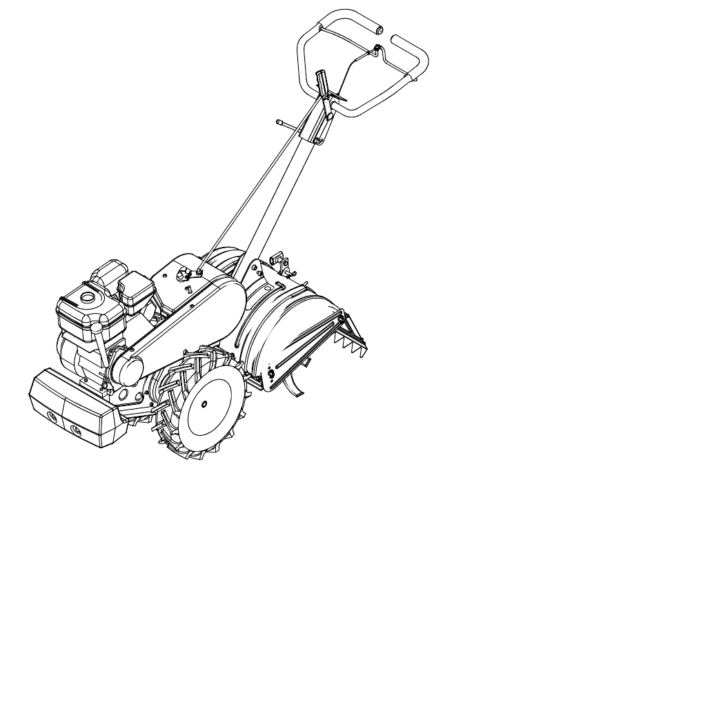
Rear Tine
Tiller
21A-450 Series
PRINTED IN U.S.A.
Warning: This unit is equipped with an internal combustion engine and should not be used on or near any unimproved forest-
covered, brush-covered or grass-covered land unless the engine’s exhaust system is equipped with a spark arrester meeting
applicable local or state laws (if any). If a spark arrester is used, it should be maintained in effective working order by the operator.
In the State of California the above is required by law (Section 4442 of the California Public Resources Code). Other states may have
similar laws. Federal laws apply on federal lands. A spark arrester for the muffler is available through your nearest engine authorized
service dealer or contact the service department, P.O. Box 368022 Cleveland, Ohio 44136-9722.
Operator’s Manual
FORM NO.
770-10194C.fm
(9/99)

2
TABLE OF CONTENTS
Content Page
Important Safe Operation Practices................................................................... 3, 4
Loose Parts ...................................................................................................... 5
Assembling Your Tiller ....................................................................................... 6
Know Your Tiller................................................................................................. 8
Operating Your Tiller.......................................................................................... 9
Making Adjustments .......................................................................................... 10
Maintaining Your Tiller ....................................................................................... 11
Service............................................................................................................... 11
Off-Season Storage ........................................................................................... 13
Troubleshooting ................................................................................................. 13
Parts List............................................................................................................ 14
FINDING MODEL NUMBER
This Operator’s Manual is an important part of your new Tiller. It will help you assemble, prepare and
maintain the unit for best performance. Please read and understand what it says.
Before you start assembling your new equipment, please locate the model plate on the
equipment and copy the information from it in the space provided below. The information on
the model plate is very important if you need help from our Customer Support Department or
an authorized dealer.
• You can locate the model number by standing in the operating position behind the unit and looking
down at the center of the rear tine cover. A sample model plate is explained below. For future
reference, please copy the model number and the serial number of the equipment in the space below.
CALLING CUSTOMER SUPPORT
If you have difficulty assembling this product or have any questions regarding the controls, operation or
maintenance of this unit, please call the Customer Support Department.
Call 1-(800)-800-7310 or 1-(330) 220-4MTD to reach a Customer Support representative.
Please have your unit’s model number and serial number ready when you call. See previous
section to locate this information. You will be asked to enter the serial number in order to
process your call.
Copy the model number here:
Copy the serial number here:
MTD PRODUCTS INC
CLEVELAND, OHIO 44136
P.O. BOX 368022

3
SECTION 1: IMPORTANT SAFE OPERATION PRACTICES
WARNING: THIS SYMBOL POINTS OUT IMPORTANT SAFETY INSTRUCTIONS WHICH, IF NOT
FOLLOWED, COULD ENDANGER THE PERSONAL SAFETY AND/OR PROPERTY OF YOURSELF
AND OTHERS. READ AND FOLLOW ALL INSTRUCTIONS IN THIS MANUAL BEFORE ATTEMPTING
TO OPERATE YOUR TILLER. FAILURE TO COMPLY WITH THESE INSTRUCTIONS MAY RESULT
IN PERSONAL INJURY. WHEN YOU SEE THIS SYMBOL— HEED ITS WARNING.
WARNING: The Engine Exhaust from this product contains chemicals known to the State of
California to cause cancer, birth defects or other reproductive harm.
DANGER: Your tiller was built to be operated according to the rules for safe operation in this manual.
As with any type of power equipment, carelessness or error on the part of the operator can result in
serious injury. This tiller is capable of amputating hands and feet. Failure to observe the following safety
instructions could result in serious injury or death.
GENERAL OPERATION
• Read this operator’s manual carefully in its entirety
before attempting to assemble this machine. Read,
understand, and follow all instructions on the
machine and in the manual(s) before operation. Be
completely familiar with the controls and the proper
use of the machine before operating it. Keep this
manual in a safe place for future and regular
reference and for ordering replacement parts.
• Your tiller is a powerful tool, not a plaything.
Therefore, exercise extreme caution at all times.
Your unit has been designed to perform one job: to
till soil. Do not use it for any other purpose.
• Never allow children under age 14 to operate the
unit. Children 14 years and older should only
operate the unit under close parental supervision.
Only responsible individuals who are familiar with
these rules of safe operation should be allowed to
use your unit.
• Do not operate tiller while under the influence of
alcohol or drugs.
• Keep the area of operation clear of all persons,
particularly small children and pets. Stop the engine
when they are in the vicinity of your tiller.
• Wear sturdy, rough-soled work shoes and close
fitting slacks and shirt. Shirt and slacks that cover
the arms and legs and steel-toed shoes are
recommended. Do not wear loose fitting clothes or
jewelry and secure hair so it is above shoulder
length. They can be caught in moving parts. Never
operate a unit in bare feet, sandals or sneakers.
• Operate tiller only in daylight or good artificial light.
• Do not start tiller unless the shift lever (if provided)
is in the neutral (N) position.
• Do not allow anyone to stand or walk in front of tiller
when starting or running engine.
• Do not place feet or hands on or near the tines
when starting the engine or while the engine is
running.
• Never attempt to make depth bar, tine width, cable,
handle, or wheel adjustments while the engine is
running.
• Do not leave the tiller unattended with the engine
running.
• Before attempting to remove rocks, bricks and
other objects from tines, stop the engine and be
sure the tines have stopped completely. Disconnect
the spark plug wire and move it away from the
spark plug.
• If your machine should start making an unusual
noise or vibration, immediately stop the engine and
allow the machine to come to a complete stop.
Disconnect the spark plug wire and move it away
from the spark plug. Take the following steps:
• Inspect for damage.
• Repair or replace any damaged parts.
• Check for any loose parts and tighten to assure
continued safe operation.
• Muffler and engine become hot and can cause a
burn. Do not touch.
• Keep all shields, guards and safety devices in place
and operating properly.
• Use caution when tilling near fences, buildings and
underground utilities. Rotating tines can cause
damage or injury.
• Do not operate engine if air cleaner or cover over
carburetor air intake is removed, except for
adjustment. Removal of such parts could create a
fire hazard.
• Only use accessories approved for this machine by
the manufacturer. Read, understand, and follow all
instructions provided with the approved accessory.
4
• If situations occur which are not covered by this
manual, use care and good judgment. Contact your
dealer for assistance.
CHILDREN
• Tragic accidents can occur if the operator is not
alert to the presence of small children. Children are
often attracted to the tilling activity. Never assume
that children will remain where you last saw them.
• Keep children out of the work area and under the
watchful eye of a responsible adult other than the
operator.
• Be alert and turn the unit off if a child enters the
area.
• Never allow children under the age of 14 to operate
the tiller.
SERVICE
• Use extreme care in handling gasoline and other
fuels. They are extremely flammable and the
vapors are explosive.
• Store fuel and oil in approved containers, away
from heat and open flame, and out of the reach of
children. Check and add fuel before starting the
engine. Never remove gas cap or add fuel while the
engine is running. Allow engine to cool at least two
minutes before refueling.
• Replace gasoline cap securely and wipe off any
spilled gasoline before starting the engine as it may
cause a fire or explosion.
• Extinguish all cigarettes, cigars, pipes and other
sources of ignition.
• Never refuel unit indoors because flammable
vapors will accumulate in the area.
• Never store the machine or fuel container inside
where there is an open flame or spark such as a
gas hot water heater, space heater, clothes dryer or
furnace.
• Never run your machine in an enclosed area as the
exhaust from the engine contains carbon
monoxide, which is a odorless, tasteless and
deadly poisonous gas.
• To reduce fire hazard, keep engine and muffler free
of leaves, grass, and other debris build-up. Clean
up fuel and oil spillage. Allow unit to cool at least 5
minutes before storing.
• Before cleaning, repairing, or inspecting, make
certain the tines and all moving parts have stopped.
Disconnect the spark plug wire and keep wire away
from spark plug to prevent accidental starting. Do
not use flammable solutions to clean air filter.
• We do not recommend the use of pressure
washers to clean your unit. They may cause
damage to electric components, spindles, pulleys,
bearings or the engine. The use of pressure
washers will result in shortened life and reduce
serviceability.
• Keep all nuts, bolts, and screws tight to be sure the
equipment is in safe working condition.
• Never tamper with safety devices. Check their
proper operation regularly.
• Do not alter or tamper with the engine’s governor
setting. The governor controls the maximum safe
operating speed of the engine. Overspeeding the
engine is dangerous and will cause damage to the
engine and to other moving parts of the machine.
WARNING — YOUR RESPONSIBILITY: Restrict the use of this power machine to persons who
read, understand and follow the warnings and instructions in this manual and on the machine.
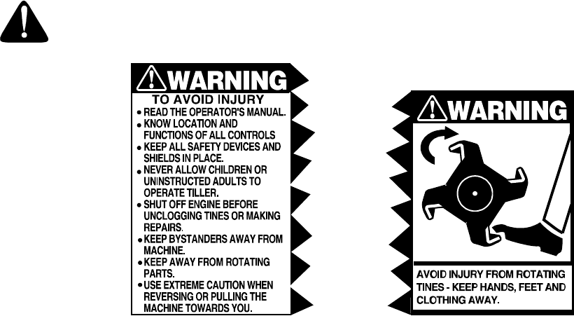
Figure 1 Safety labels found on your unit
5
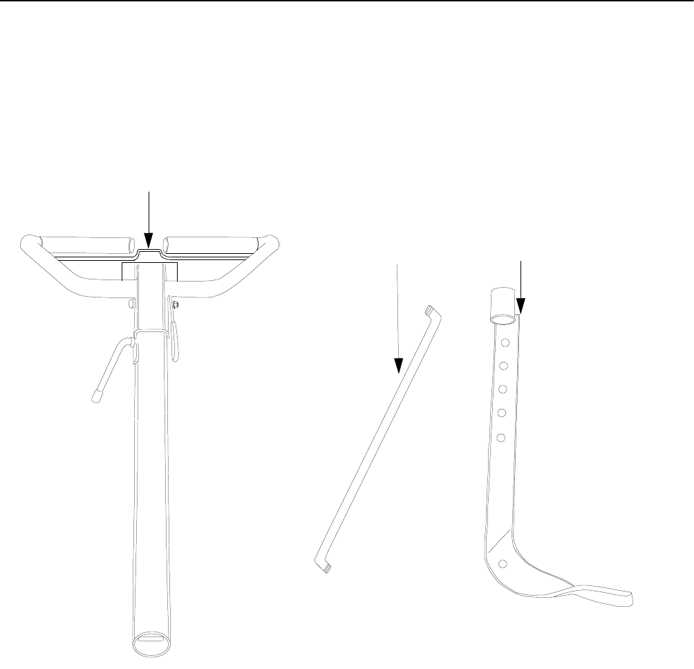
SECTION 2: LOOSE PARTS
Handle
Assembly
Depth
Stake
Assembly
Control
Rod
NOTE: Cable tie not shown.
6
SECTION 3: ASSEMBLING YOUR TILLER
IMPORTANT:
This unit is shipped WITHOUT GASOLINE
or OIL. After assembly, see separate engine manual for
proper fuel and engine oil recommendations.
NOTE: Left and right is determined from the operator’s
position, standing behind the tiller.
TOOLS REQUIRED FOR ASSEMBLY
Adjustable Wrenches
Pair of Pliers
Screw Driver
TO REMOVE UNIT FROM CARTON
• Remove staples, break glue on top flaps, or cut
tape at carton end and peel along top flap to open
carton.
• Remove loose parts included with unit (i.e.,
operator’s manual, etc.).
• Cut corners and lay carton down flat.
• Remove packing material.
• Roll or slide unit out of carton. Check carton
thoroughly for loose parts.
• Extend control cable and lay on the floor. Be careful
not to bend or kink control cable.
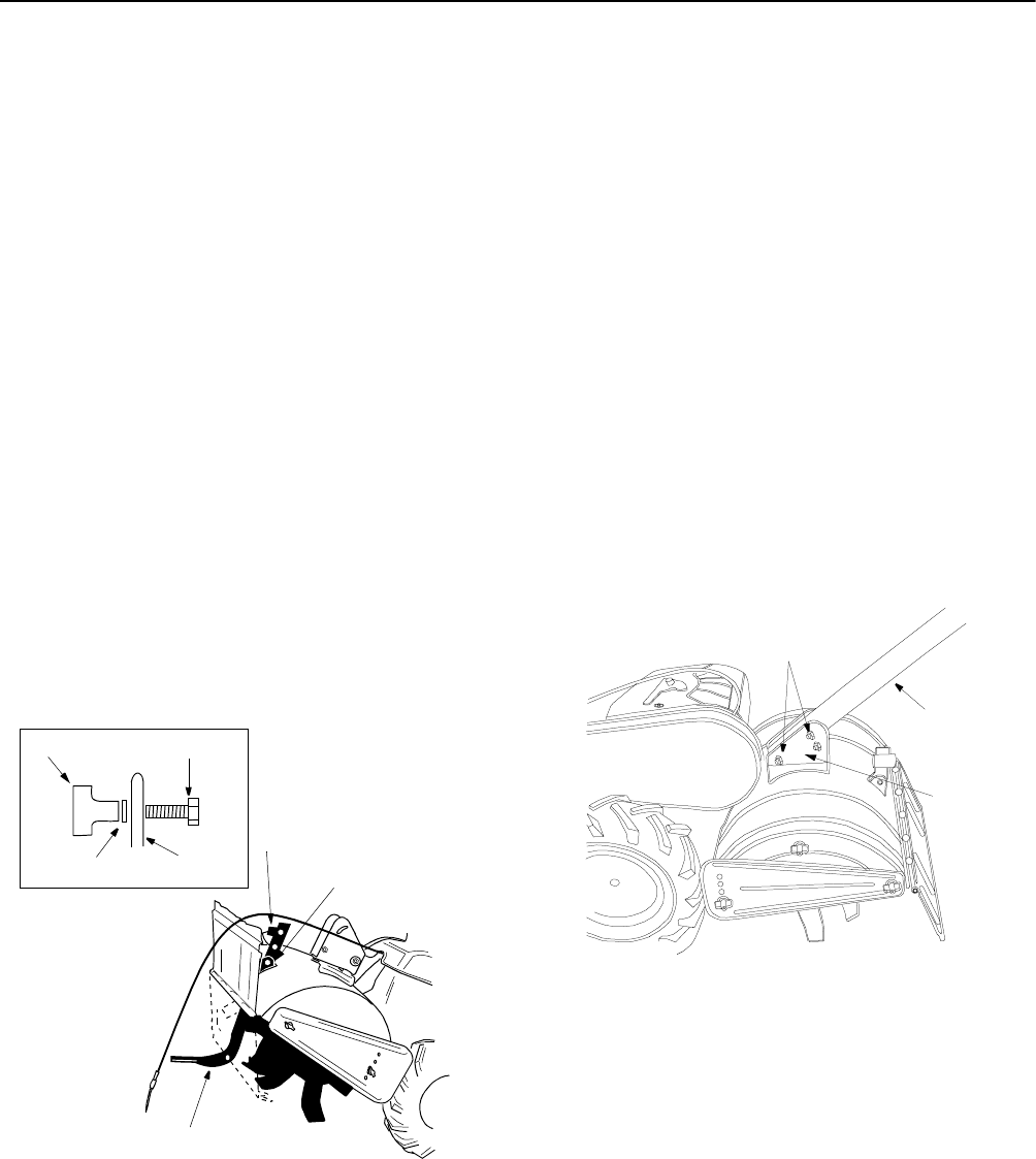
Figure 2
ATTACHING DEPTH STAKE ASSEMBLY
• Tip the tiller forward so it rests on front
counterweight.
• Raise the tine shield hinge flap assembly. Remove
"T" knob, flat washer and hex bolt from depth stake.
Insert the depth stake assembly in front of spacer
(under the tine shield) and up through the tine
shield assembly as shown in Figure 2.
• Insert clevis pin through the tine shield and the
second hole from top of the depth stake. Secure
with hairpin clip.
• Insert hex bolt into the top hole of the depth stake
assembly. Place flat washer on hex bolt and thread
“T” knob onto the hex bolt. See Figure 2. Tighten
securely.
• Tip the tiller back down so it rests on the depth
stake (transport position).
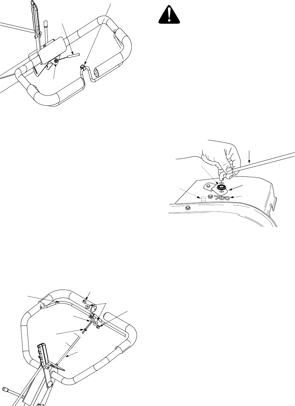
ATTACHING THE HANDLE ASSEMBLY
Figure 3
• Remove top two bolts and flange lock nuts from
handle mounting brackets as shown in Figure 3. Do
not remove the bottom bolt and nut.
• Place handle assembly in position between the
handle mounting brackets. See Figure 3.
• Line up holes in handle with holes in handle
mounting brackets. Secure with hardware removed
in step 1.
T-Knob Hex Bolt
Washer
Depth
StakeStake
T-Knob
Hex Bolt
Washer
Clevis Pin
Hairpin Clip
Depth Stake
Remove
Handle
Ass’y
Handle
Bracket
7
Figure 4
ATTACHING THE CLUTCH CABLE
Attach the clutch cable to the handle as follows (be
careful not to kink the cable).
• Remove threaded eyebolt and nut from the end of
the cable.
• Route the clutch cable to the right side of the
handle mounting brackets and underneath the
handle.
• Push the cable through the hole in the center of the
handle and snap in the plastic fitting. See Figure 4.
• Remove slot head screw, nut and two flat washers
from the clutch bail.
• Fasten the threaded eyebolt onto bail as shown in
Figure 5. The parts go together from top to bottom
as follows: Slot Head Screw, Flat Washer, Clip,
Eyebolt, Flat Washer and 1/4” Nut.
• Thread eyebolt and #10 nut, removed in step 1, into
the internally threaded tube at the end of the cable.
Thread engagement should be about 3/4”. Tighten
nut against tube at end of cable. See Figure 5.
Figure 5
NOTE: Do not overtighten clutch cable. Too much
tension may cause it to break.
WARNING: Be certain to check the
clutch cable adjustment as instructed on
this page before operating the tiller.
Secure clutch cable to handle using cable tie. Refer to
Figure 7. Cut off excess end of cable tie.
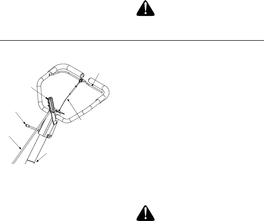
ATTACHING THE CONTROL ROD
• Remove hairpin clips from control rod, (rubber
washers to remain on control rod).
• Insert the shorter, (angled), end of the control rod
through the indicator bracket on the shift cover and
secure with hairpin clip that was removed in step 1.
See Figure 6.
• Insert the longer end of the control rod through the
hole in the gear selector handle and secure with
hairpin clip.See Figure 7.
.
Figure 6
CHECKING THE CLUTCH ADJUSTMENT
IMPORTANT:
Service the engine with oil and gasoline
before checking this adjustment. Refer to the separate
engine manual packed with your tiller for proper fuel
and engine oil recommendations.
Position the tiller so the front counterweight is against a
solid object, such as a wall. With the gear selection
lever in NEUTRAL, start the engine. Refer to the
separate engine manual.
Standing on the right side of the tiller, examine the belt
(inside the belt cover). It should not be turning.
NOTE: Do not put fingers under the belt cover.
If the belt turns without bail engaged, adjust by
unthreading the internally threaded tube at the end of
the cable a few turns clockwise (when standing in
operator’s position), and then retighten the nut against
the tube.
Plastic Fitting
Internally Threaded
Tube
Sl
ot
H
ea
d
S
crew,
Nut, Flat Washers
Slot Head Screw
Flat Washers
Threaded
Eyebolt
Internally
Threaded
Tube
Clutch
Bail
3/4”
1/4”
Nut
#10
Nut
Indicator Bracket
Rubber
Washer
Control Rod
Hairpin
Clip
Idler
Pulley
Rod
8
Now move the shift lever to FORWARD (Wheels
Forward) position. Carefully engage the clutch by lifting
the clutch control bail against the handle. The wheels
should spin.
If the wheels do not spin with the unit in forward,
adjust by unthreading the tube at the end of the cable a
few turns counter-clockwise, (when standing in
operator’s position), and then retighten the nut against
the tube.
Recheck both adjustments, and readjust as necessary.
NOTE: A secondary cable adjustment is available if you
reach the point that additional adjustment is needed.
Remove the belt cover and move the hex nuts at the
other end of the cable towards the end of the casing.
Then readjust the hex nuts at the handle.
TIRE PRESSURE
The tires on your unit may be over-inflated for shipping
purposes. Reduce the tire pressure before operating
the unit. Recommended operating tire pressure is
approximately 20 p.s.i. (check sidewall of tire for tire
manufacturer’s recommended pressure).
WARNING: Maximum tire pressure
under any circumstances is 30 p.s.i.
Equal tire pressure should be maintained
on both tires.
SECTION 4: KNOW YOUR TILLER
Figure 7
THROTTLE CONTROL
The throttle control lever is located on the engine. It
controls the engine speed and stops the engine. See
Engine manual for further information.
CHOKE LEVER
The choke lever is located to the left of the throttle. It is
used to enrich the fuel mixture in the carburetor when
starting a cold engine. See Engine manual for further
information.
GEAR SELECTION HANDLE
The gear selection handle is located in the center of the
handle on the tiller. It is used to select NEUTRAL,
REVERSE, or one of the FORWARD modes (see
below). Pull or push the handle so that the indicator on
top of shift cover points to the operating mode desired.
See Figure 7.
NEUTRAL—Transmission is in neutral.
REVERSE—Reverse wheel drive.
FORWARD Modes:
Wheels Forward— Forward wheel drive only.
Tines Reverse— Forward wheel drive and reverse tine
drive.
Tines Forward— Forward wheel and tine drive.
WARNING: Make certain unit is in
NEUTRAL when starting the engine.
NOTE: If difficulty is encountered in moving the gear
selection handle, move the tiller forward or backward
slightly to allow the gears to synchronize.
Height
Adjustment
Lever
Control
Rod
Gear
Selection
Handle
Clutch
Control
Bail
Clutch
Cable
Cable Tie

9
CLUTCH CONTROL BAIL
The clutch control bail is located below the handle. See
Figure 7. Lifting the clutch control bail against the
handle engages the wheel and tine drive mechanisms.
NOTE: Never engage clutch lever while shifting.
DEPTH STAKE
The depth bar controls the tilling depth. Refer to
SECTION 5: OPERATING YOUR TILLER on this page.
HANDLE ADJUSTMENT
The handle may be adjusted to be raised or lowered in
line with the tiller. To adjust the handle position loosen
the handle height adjustment crank a few turns. Pivot
handle up or down to desired position. Tighten crank.
SECTION 5: OPERATING YOUR TILLER
NOTE: Engine is shipped without oil.
WARNING: Use the reverse tine drive
when tilling virgin ground, sod or hard
soil. Use the forward tine drive when
cultivating or tilling soft ground.
BEFORE STARTING
•Service engine with oil as instructed in the
separate engine manual packed with your unit.
• Fill fuel tank with clean, fresh, lead-free, low-lead or
regular grade leaded gasoline.
TO START ENGINE
WARNING: Be sure no one is standing
in front of the tiller while the engine is
running or being started.
• Place the throttle control lever in the FAST (rabbit)
position.
• Move choke lever to CHOKE position.
NOTE: A warm engine may not require choking.
• Stand at side of tiller. Grasp the starter handle with
your right hand and pull out slowly, until it pulls
slightly harder. Place your left hand on the lower
portion of the upper handle.
• Pull starter handle rapidly. Do not allow handle to
snap back. Allow it to rewind slowly while keeping a
firm hold on the starter handle.
• Repeat steps 3 and 4 until engine starts.
• As engine warms up and begins to operate evenly,
move choke lever gradually to RUN position. If
engine falters, return to choke position, then slowly
move to RUN position.
• Refer to engine manual for additional engine
information.
NOTE: After starting engine and prior to using the tiller,
be certain to check the clutch adjustment as described
in “Checking the Clutch Adjustment” section of
Assembly Instructions.
TO STOP ENGINE
• Move throttle control to the STOP position.
• Disconnect spark plug wire and ground to prevent
accidentally starting while equipment is
unattended.
NOTE: After the first ten hours of operation, recheck
the clutch adjustment. Refer to “Checking the Clutch
Adjustment” section of the Assembly Instructions.
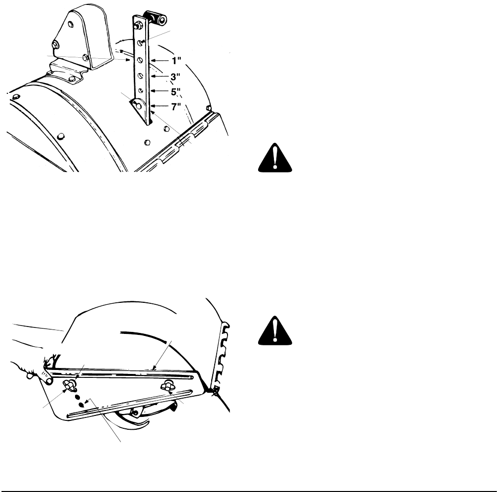
WARNING: When operating the tiller for
the first time, use the depth stake setting
that gives 1 inch of tilling depth (second
hole from the top). See Figure 8.
Tilling depth is controlled by the depth stake which can
be adjusted to five different settings. See Figure 8.
Adjust the side shields as shown in Figure 9, as you
adjust the depth stake. Be certain spark plug wire is
disconnected and grounded against the engine.
• When using the tiller for the first time, use the
second adjustment hole from the top (1" of tilling
depth). See Figure 8.
• When breaking up sod and for shallow cultivation,
use the setting which gives 1" of tilling depth
(second hole from the top). Place the side shields in
their lowest position. For further depth, raise the
depth stake and side shields and make one or two
more passes over the area.
• When tilling loose soil, depth stake may be raised
to its highest position (use bottom adjustment hole)
to give the deepest tilling depth. Raise the side
shields to their highest position.
10
Figure 8
•To transport tiller, lower the depth stake (use top
adjustment hole).
•To adjust the depth stake, remove the clevis pin
and hairpin clip. See Figure 8. Move the depth
stake to the desired setting.
•To adjust the side shields, remove the front wing
nut and loosen the rear wing nut. See Figure 9.
Place side shield in position desired. Replace wing
nuts and tighten securely.
Figure 9
TO OPERATE THE TILLER:
•Select the depth stake setting.
•Start engine as instructed on page 9.
•Move gear selection handle to one of the forward
modes or reverse.
Use the reverse tine drive when tilling virgin
ground, sod or hard soil. Use the forward tine
drive when cultivating or tilling soft ground.
IMPORTANT:
When using the forward tine drive, lower
the depth stake (use a shallower tilling depth) to make
certain the tines do not run across the ground.
WARNING: Do not move the gear
selection handle with the wheels or tines
engaged. Make certain the unit is stopped
completely before changing the gear
selection.
•Squeeze the clutch control bail against the handle
to engage the wheels and tines.
NOTE: Make certain the gear selection indicator is
correctly positioned before engaging the clutch handle.
If it is between gears, the engine will stall.
To transport tiller, do not engage the tines. Select the
wheel drive only.
WARNING: Do not push down on the
handles so that the wheels are lifted off
the ground while using the reverse tine
drive, or the tiller could move backward
and cause personal injury.
For best results, it is recommended the garden be tilled
twice (lengthwise, then widthwise) to pulverize the soil.
SECTION 6: MAKING ADJUSTMENTS
HANDLE ADJUSTMENT
The handle height may be adjusted. Refer to the Know
Your Tiller section for details of handle adjustment.
BELT TENSION ADJUSTMENT
Periodic adjustment of the belt tension may be required
due to normal stretch and wear on the belt. Adjustment
is needed if the tines or wheels seem to hesitate while
turning, but the engine maintains the same speed.
To adjust the tension on the belt, refer to clutch
adjustment information in “Checking the Clutch
Adjustment” section of the Assembly Instructions. After
belt tension has been adjusted, if the belt is excessively
stretched, you may need to adjust the idler pulley rod.
This can easily be checked. With the engine off and the
clutch control bail disengaged, shift the gear selection
handle to each forward mode. If the indicator bracket
touches the idler pulley rod, (with the clutch control bail
disengaged), then an adjustment is necessary.
•Disconnect and ground out spark plug wire against
the engine.
Use This
Position
First Time
Transport
Position
Clevis
Pin
Hairpin
Clip
Use This
Hole for
Lowest (Shallowest)
Position
Use This Hole for
Highest (Deepest)
Position
Side
Shields
Front
Wing Nut
Rear
Wing Nut

11
• Remove the belt cover as described in the belt
replacement section on page 12.
• Remove the hairpin clip and spring washer from the
idler pulley rod. See Figure 11.
• Move the idler pulley rod to the lower hole in the
idler bracket. See Figure 11.
• Replace the spring washer and hairpin clip.
• Check clearance of the idler pulley rod to the
indicator bracket by shifting to each forward mode,
as before.
CARBURETOR ADJUSTMENT
WARNING: If any adjustments are made
to the engine while the engine is running,
(e.g. carburetor), disengage all clutches
and tines. Keep clear of all moving parts.
Be careful of heated surfaces and muffler.
Never make unnecessary adjustments. The factory
settings are correct for most applications. If
adjustments are needed, refer to the separate engine
manual packed with your tiller.
SECTION 7: SERVICE
Transmission—The transmission is pre-lubricated and
sealed at the factory. It requires no checking unless the
transmission is disassembled. To fill with grease, lay
the right half of the transmission on its side. Add 30
ounces of Benalene 920 grease. Apply a bead of RTV
or silicone sealant to the right half of the transmission,
all the way around the gear compartment. Assemble
the left half to it. This grease can be obtained at your
nearest authorized dealer. Order part number 737-
0300.
Clutch Bail—Lubricate the pivot point on the clutch bail
and the cable at least once a season with light oil. The
control must operate freely in both directions.
Pivot Points—Lubricate all pivot points and linkages at
least once a season with light oil.
Tine Shaft—Remove tines at least once a season and
lubricate with oil.
Wheel Axle—Remove the wheel assemblies at least
once a season and lubricate with oil.
SECTION 8: MAINTAINING YOUR TILLER
WARNING: Disconnect the spark plug
wire and ground it against the engine
before performing any repairs or
maintenance.
ENGINE
Refer to the separate engine manual for engine
maintenance instructions.
Maintain engine oil as instructed in the separate
engine manual packed with your unit. Read and follow
instructions carefully.
Service air cleaner every ten hours under normal
conditions. Clean every hour under extremely dusty
conditions. Poor engine performance and flooding
usually indicates that the air cleaner should be
serviced. To service the air cleaner, refer to the
separate engine manual packed with your unit.
IMPORTANT:
Never run your engine without air cleaner
completely assembled.
The spark plug should be cleaned and the gap reset
every 25 hours of engine operation. Spark plug
replacement is recommended at the start of each tiller
season; check engine manual for correct plug type and
gap specification.
Clean the engine regularly with a cloth or brush. Keep
the cooling system (blower housing area) clean to
permit proper air circulation which is essential to engine
performance and life. Be certain to remove all dirt and
combustible debris from muffler area.
12
CLEANING THE TINE AREA
Clean the underside of the tine shield after each use.
The dirt washes off the tines easier if washed off
immediately instead of after it dries.
We do not recommend the use of pressure washers to
clean your unit. They may cause damage to electric
components, spindles, pulleys, bearings, or the engine.
The use of pressure washers will result in shortened life
and reduce serviceability.
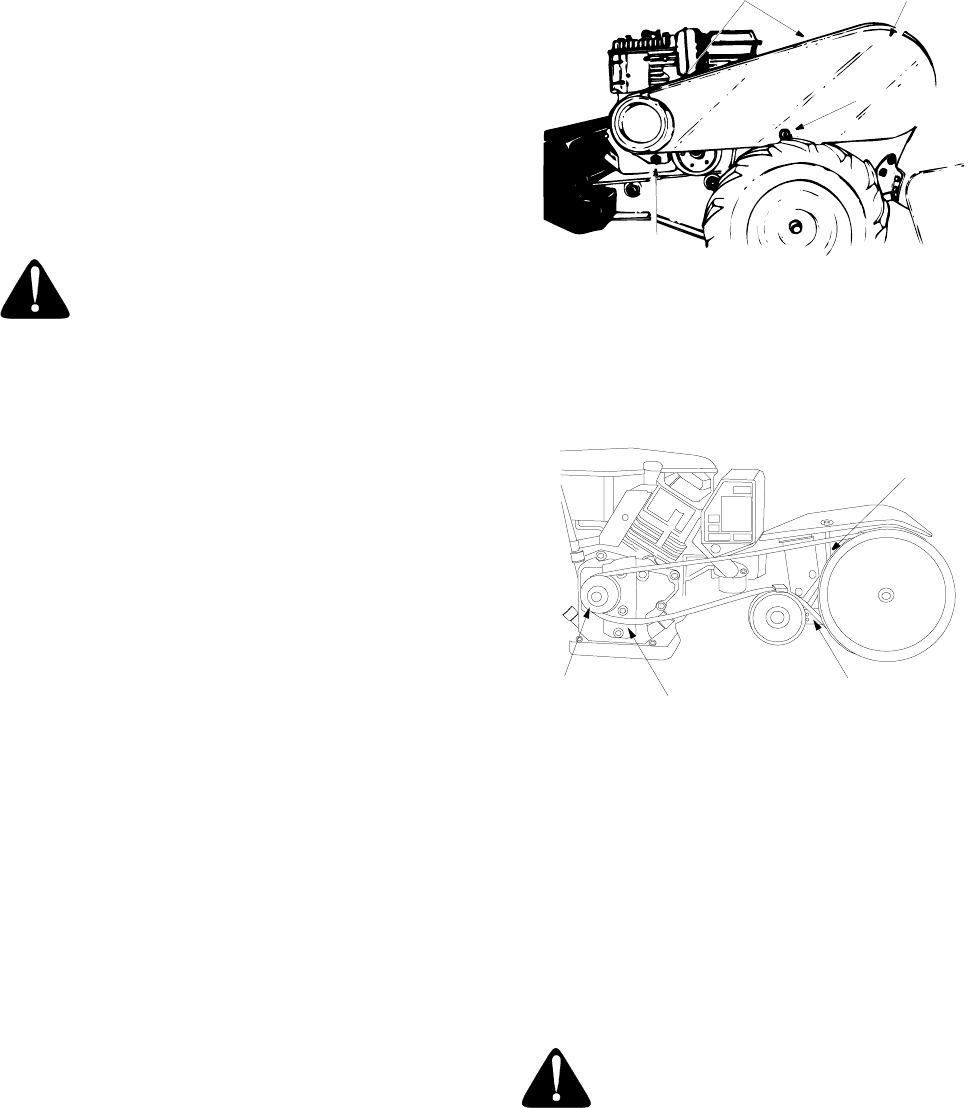
BELT REPLACEMENT
CAUTION: Do not use an off-the-shelf
belt.
Your tiller has been engineered with a belt made of
special material (Kevlar Tensile) for longer life and
better performance. It should not be replaced with an
off-the-shelf belt.
If belt replacement is required, order belt by part
number from your nearest authorized dealer.
Part No. 754-0434—‘‘V’’ Belt
• Disconnect and ground the spark plug wire against
the engine.
• Remove the belt cover from the left side of the tiller
as follows: See Figure 10.Remove two torx screws
from the top of belt cover.
• Remove the hex cap nut and flat washer from the
side of the belt cover. Remove the self-tap screw at
the bottom of the front of the cover.
• Remove the belt keeper bracket located behind the
engine pulley by removing two hex bolts and lock
washers. See Figure 11.
• Remove belt. Reassemble new belt, following
instructions in reverse order.
Figure 10
Upon reassembly, make certain the belt is routed over
the idler pulley and inside of belt keepers by engine
pulley. See Figure 11.
Figure 11
TIRES
Recommended operating tire pressure is
approximately 20 p.s.i. (check sidewall of tire for tire
manufacturer’s recommended pressure). Maximum tire
pressure under any circumstances is 30 p.s.i. Equal tire
pressure should be maintained on both tires.
When installing a tire to the rim, be certain rim is clean
and free of rust. Lubricate both the tire and rim
generously. Never inflate to over 30 p.s.i. to seat beads.
WARNING: Excessive pressure (over 30
p.s.i.) when seating beads may cause tire/
rim assembly to burst with force
sufficient to cause serious injury.
Torx Screws Belt Cover
Hex Cap Nut
Self Tap
Screw
Flat Washer
Engine
Pulley Belt Keeper Idler
Brkt.
Idler
Pulley
Rod
Brkt.

13
SECTION 9: OFF-SEASON STORAGE
If the tiller will not be used for a period longer than 30
days, the following steps should be taken to prepare the
tiller for storage.
•Clean the exterior of engine and the entire tiller
thoroughly. Lubricate the tiller as described in the
lubrication instructions.
•We do not recommend the use of pressure
washers to clean your unit. They may cause
damage to electric components, spindles, pulleys,
bearings or the engine. The use of pressure
washers will result in shortened life and reduce
serviceability.
•Refer to the engine manual for correct engine
storage instructions.
•Wipe tines with oiled rag to prevent rust.
•Store tiller in a clean, dry area. Do not store next to
corrosive materials, such as fertilizer.
NOTE: When storing any type of power equipment in
an unventilated or metal storage shed, care should be
taken to rustproof the equipment. Using a light oil or
silicone, coat the equipment, especially any springs,
bearings and cables.
SECTION 10: TROUBLE SHOOTING GUIDE
NOTE: For repairs beyond the minor adjustments above, contact your local authorized service dealer.
Trouble Possible Cause(s) Corrective Action
Engine fails to
start
Fuel tank empty, or stale fuel.
Throttle control lever not in correct
starting position (if so equipped).
Blocked fuel line.
Dirty aircleaner.
Choke not in ON position.
Spark plug wire disconnected.
Faulty spark plug.
Engine flooded.
Fill tank with clean, fresh gasoline. Fuel will not last over
thirty days unless a fuel stabilizer is used.
Move throttle lever to start position.
Clean fuel line.
Refer to the engine manual packed with your unit.
Move switch to ON position.
Connect wire to spark plug.
Clean, adjust gap or replace.
Refer to the engine manual packed with your unit.
Engine runs
erratic
Unit running on CHOKE.
Spark plug wire loose.
Blocked fuel line or stale fuel.
Vent in gas cap plugged.
Water or dirt in fuel system.
Dirty air cleaner.
Carburetor out of adjustment.
Move choke lever to OFF position.
Connect and tighten spark plug wire.
Clean fuel line; fill tank with clean, fresh gasoline. Fuel will
not last over thirty days unless a fuel stabilizer is used.
Clear vent.
Drain fuel tank. Refill with fresh fuel.
Refer to the engine manual packed with your unit.
Refer to the engine manual packed with your unit.
Engine over-
heats
Engine oil level low.
Dirty air cleaner.
Air flow restricted.
Carburetor not adjusted properly.
Fill crankcase with proper oil.
Refer to the engine manual packed with your unit.
Refer to the engine manual packed with your unit.
Adjust carburetor as instructed in separate engine manual.
Tines do not
engage
Foreign object lodged in tines.
Tine clevis pin(s) missing.
Pulley and idler not in correct
adjustment.
Not shifting properly.
Control cable not adjusted properly.
Belt worn and/or stretched.
Dislodge foreign object.
Replace tine clevis pin(s).
Take unit to authorized service dealer.
Refer to Controls section of operator’s manual for proper
shifting procedures.
Adjust control cable (see assembly instructions).
Replace belt.
Tines skip over
ground
Improper rotation. Forward rotation should only be used on soil that has
already been tilled, not on virgin soil.
Wheels do not
engage
Clevis pin missing.
Tiller is not being shifted properly.
Control cable not adjusted properly.
Belt worn and/or stretched.
Replace clevis pin.
Refer to Controls section of operator’s manual for proper
shifting procedures.
Adjust control cable (see assembly instructions).
Replace belt.

14
SECTION 11: PARTS LIST FOR MODEL 450 SERIES

15
MODEL 450 SERIES
REF.
NO. PART NO. DESCRIPTION
1 611-0020 Wheel Shaft Ass’y: 33T
2 611-0021 Tine Shaft Ass’y: 18T
3 611-0128 Jack Shaft Ass’y
4 611-0129 Input Shaft Ass’y
5 617-0058 Rev. Idler Gear Ass’y: 30T
6 617-0059 Ftine Idler Gear Ass’y: 30T
7 617-0060 Tine Input Sprocket Ass’y: 9T
8 617-0061 Wheel Input Sprocket Ass’y: 10T
9 617-0062 Gear Ass’y: 11T
10 686-0108 R.H. Housing Ass’y
11 710-0376 Hex Bolt 5/16-18 x 1" Lg.
12 710-0599 Hex S-Tap Scr. 1/4- 20 x .5"
13 710-0604 Hex S-Tap Scr. 5/16-18 x .625"
14 710-3008 Hex Bolt 5/16-18 x .75"
15 711-1349 Input Shaft
16 712-0378 Hex Nut 7/16-20
17 712-3004A Flange Nut 5/16-18
18 713-0367 #420 Chain 1/2 Pitch x 50 Links
19 713-0484 #50 Chain 5/8 Pitch x 54 Links
20 716-0865 Snap Ring
21 717-0853 Shifting Fork
22 717-1582 Spur Gear 44T
23 717-1583 Spur Gear 30T
24 717-1584 Spur Gear 30T
25 717-1585 Spur Gear 44T
26 717-1587 Spur Gear 44T
27 717-1594 Spur Gear 16T
28 721-0378 Seal 1.0 Shaft
29 721-0379 Seal .75 Shaft
31 726-0277 Taper Cap Ring
32 732-0496 Compression Spring .50" Lg.
33 736-0163 Thrust Wash. 1.03" I.D. x 1.62" O.D.
34 736-0351 Fl-Wash .76" I.D. x 1.5" O.D.
35 736-0407 Bell-Wash .45" I.D. x 1.0"
36 736-0518 Thrust Wash. .445 x 1.92 x .060
37 736-3088 Fl-Wash. .635" I.D. x 1.59 O.D.
40 738-0645 Detent Shaft 1/2" Dia.
41 738-0648 Jack Shaft .625 x 2.385
42 738-1013 Jack Shaft .625 x 5.0
43 741-0124 Ball Bearing
44 741-0420 Flange Bearing 1.0 x 2.5 x 1.38
45 741-0421 Flange Bearing .75 x 2.5 x 1.38
46 741-0563 Ball Bearing . 6692 x 5745 x .466
47 741-0862 Detent Ball .250
48 750-0258 Spacer .315
49 750-0570 Spacer 1.0 I.D x 2.0 O.D. x .440
50 750-0664 Spacer .505 I.D. x .88 O.D. x .440
51 750-0671 Spacer .75 x 2.0 x .50
52 786-0171 L.H. Chain Case Ass’y
53 786-0238 Gear Positioner Bracket
- 737-0300 Benelene 920 Grease
- 737-0288 Never Seez Grease
- 686-0107 Gear Case Assembly Complete
REF.
NO. PART NO. DESCRIPTION
NOTE: For painted parts, please refer to the list of color codes below. Please add the applicable color code, wherever
needed, to the part number to order a replacement part. For instance, if a part numbered 700-xxxx is painted Oyster Gray, the
part number to order would be 700-xxxx-0662.
Black — 0691; Black, Powder — 0637; Blue, Midnight — 0667; Charcoal — 0483; Grey — 0648;
Grey, Oyster — 0662; Orange — 0606; Red — 0650; Red, MTD — 0638; Silver — 0629; Yellow — 0674.
16
MODEL 450 SERIES
20
18
8
23
10
1
60
61
37
62
25
34
27
64
30 39
27 63 26
32 36
33
31
29
66
26
41
30
30
24
28
35
40
26
49
44
50
59
51
65 53
55
56
54
57
58
44
46
42
4
9
11
16
6
3
14
7
19
5
17
2
6061
12 15
12
12
38
21
22
67
70
70
68
69

17
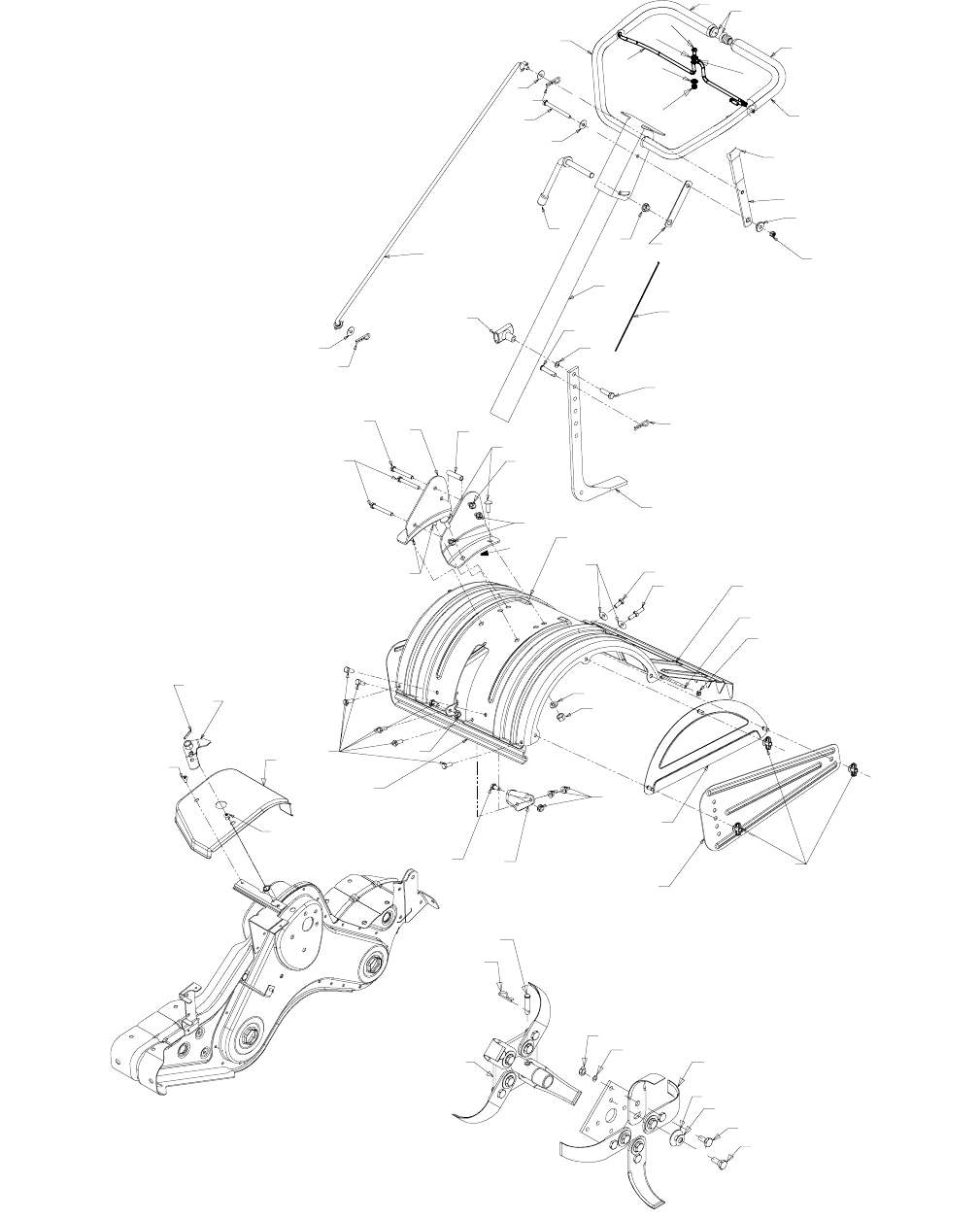
MODEL 450 SERIES
REF.
NO. PART NO. DESCRIPTION
1 747-1152 Shift Rod
2 649-0041 Upper Handle Ass’y
3 649-0034 Lower Handle Ass’y
4 710-3005 Hex Screw 3/8-16 x 1.25
5 710-3056 Hex Screw 5/16-18 x 3.25
6 711-0415 Clevis Pin 3/8-1.62
7 712-0379 Flange Lock Nut 3/8-24
8 712-0429 Hex Lock Nut 5/16-18
9 714-0147 Cotter Pin
10 720-0313 Grip
11 720-0210A T-Knob
12 720-0278A Foam Grip
14 726-0317 Cable Tie
15 735-0246 Plug
16 736-0117 Flat Washer 3/8 x .620 x .033
17 736-0242 Bell Wash. .340 I.D. x .872 O.D.
18 738-0958 Shoulder Spacer
19 784-0190 Handle Adjustment Crank
20 784-0191 Hex Nut Ret. Bracket
21 786-0120 Depth Stake
22 747-1219 Bail Clutch
23 786-0181 Shift Lever Rod
24 686-0044A Tine Shield Cover Ass’y
25 710-0176 Hex Cap Screw 5/16-18 x 2.75
26 710-3008 Hex Cap Screw 5/16-18 x .750
27 710-3097 Carriage Bolt 3/8-16 x 1.0
28 712-0421 Wing Nut
29 736-0169 Lock Washer 3/8
30 712-3004A Flange Nut 5/16-18
31 726-0106 Cap Nut
32 738-0849 Hex Screw 5/16-18 x .75" Lg.
33 747-0432 Rod
34 750-0885 Spacer .435 O.D. x .322 I.D.
35 786-0090 Shoulder
36 786-0113 Tine Shield Hinge Flap
37 786-0176 R.H. Handle Brkt.
38 786-0177 L.H. Handle Brkt.
39 786-0178 Tine Shield
40 786-0179 Tine Shield Brkt.
41 786-0180 Shoulder Spacer Brkt.
42 686-0109 Shift Crank Ass’y
44 710-1017 Screw 1/4-14 x .625
46 715-0120 Spirol Pin 3/16 x 1.00
49 784-0208C Shift Cover
50 711-0415 Clevis Pin
51 712-3054 Hex Nut 3/8-24 Thd.
53 742-0305 13" Dia. Articulating Tine
54 738-0689 Shld. Bolt 1/2" DIa. x .175
55 736-0208 Fl-Wash. .51" I.D. x 1.50"
56 736-0253 Bell-Wash. .515" I.D. x 1.14"
57 738-0688 Shld. Bolt 1/2" Dia x .320
58 784-0160 Tine Adapter Ass’y 18"
59 714-0149B Internal Cotter Pin
60 735-0127 Rubber Washer
61 714-0104 Cotter Pin
62 710-3022 Hex Screw 3/8-16 x 2.75" Lg.
63 736-0204 Flat Washer
64 712-0431 Flange Nut .344 I.D. x .62 O.D.
65 736-0169 Lock Washer
66 712-0798 Hex Nut 3/8-16
67 710-0946 Truss Screw 1/4-20 x .65
68 712-0324 Hex Lock Nut 1/4-20 Gr. 8
69 726-0273 Battery Hose Clamp 5/16
70 736-3090 Flat Washer .260 x .720 x .060
REF.
NO. PART NO. DESCRIPTION
Labels
Ref.
No. Part No. Code Description
N/I 777S30037 Model Plate
N/I 777I20282 Shift Plate Facing Operator
N/I 777D02195 Engine Spinner
N/I 777D01524 YM, Side of Belt Guard
N/I 777I20358 Place Hand Here on Handle
N/I 777I20451 Gear Selection on Handle
18
MODEL 450 SERIES
18
17 24
19
27
46
45 12
26
9
6
18
25
14 28
20
2
11
44
4
22
23
16
5
21 7
13
15
340
43
42
41
39
32 33
31
30
29
36
34
37
37
38
35
10

19
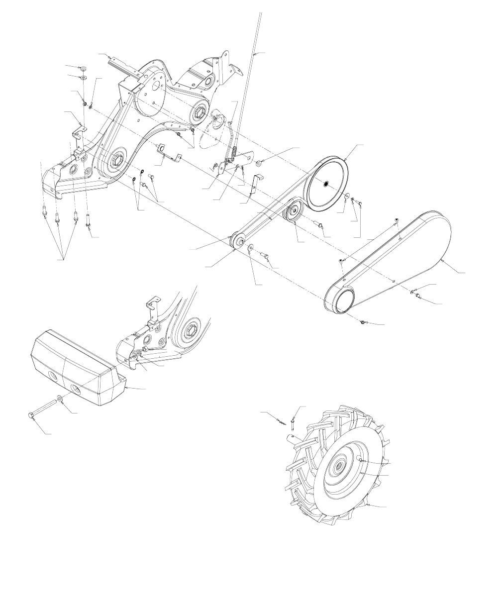
MODEL 450 SERIES
REF.
NO. PART NO. DESCRIPTION
1 686-0111 Belt Cover Brkt. Ass’y
2 710-0237 Hex Bolt 5/16-24 x .62" Lg.
3 710-0412 Hex Bolt 1/4-28 x .75" Lg.
4 710-0502A Hex Wash.TT-Sems Screw 3/8-16 x
1.250" Lg.
5 710-0591 Hex Bolt 3/8-24 x 1.00
6 710-0599 Hex Wash. Hd. S-Tap Scr.
7 710-0723 Hex Cap Screw 3/8-16 x 1.25
8 712-0266 Ctr. Lock Jam Nut 3/8-16
9 712-0267 Hex Nut 5/16-18
10 714-0104 Internal Cotter Pin
11 736-0104 Hairpin Clip
12 736-0119 L-Wash. 5/16" I.D.
13 736-0176 Fl-Wash. 1/4 I.D. x .93 O.D.
14 736-0271 Spring-Wash. .317 x .625 O.D. x .099
15 736-0329 L-Wash. 1/4" I.D.
16 736-0452 Bell-Wash. .396 x 1.140 x .095
17 738-0876 Shld. Nut 7/16-20
18 746-1117 Clutch Cable
19 747-1159 Idler Pulley Rod
20 754-0434 Belt: 4L x 58.16 Lg.
21 756-0405 Fl-Idler w/Flange 3.75" O.D.
22 756-0971 Outer Engine Pulley Half
23 756-0972 Inner Engine Pulley Half
24 756-1162 Input Pulley
25 786-0064A Idler Bracket
26 786-0186 Belt Keeper Brkt.
27 786-0187 Shift Cover Brkt.
28 786-0193 Idler Belt Keeper
29 634-0110 RH Wheel Ass’y Comp. 16.0 x 4.0
634-0111 LH Wheel Ass’y Comp. 16.0 x 4.0
734-1796 Tire Only 16.0 x 4.0
30 634-0112 Wheel Rim Ass’y Comp.
31 734-0255 Air Valve
32 711-1017 Clevis Pin
33 714-0104 Internal Cotter Pin
34 710-0382 Hex Bolt 1/2-13 x 5.00" Lg.
35 712-0206 Hex Nut 1/2-13 Thd.
36 723-0381 Counterweight
37 736-0326 Fl-Wash. .510" I.D. x 1.0" O.D.
38 736-0921 L-Wash. 1/2" Lg.
39 710-0653 Hex Screw 1/4-20 x .375" Lg.
40 710-1017 Screw 1/4-14 x .625" Lg.
41 712-0392 Acorn Lock Nut
42 736-0463 Fl-Washer 1/4 x .620" Lg.
43 784-0158A Belt Cover
44 710-0805 Hex Bolt 5/16-18 x 1.50" Lg.
45 736-0242 Bell-Wash. .340 I.D. x .872 O.D.
46 712-3010 Nut:Hex 5/16-18
REF.
NO. PART NO. DESCRIPTION
NOTE: For painted parts, please refer to the list of color codes below. Please add the applicable color code, wherever
needed, to the part number to order a replacement part. For instance, if a part numbered 700-xxxx is painted Oyster Gray, the
part number to order would be 700-xxxx-0662.
Black — 0691; Black, Powder — 0637; Blue, Midnight — 0667; Charcoal — 0483; Grey — 0648;
Grey, Oyster — 0662; Orange — 0606; Red — 0650; Red, MTD — 0638; Silver — 0629; Yellow — 0674.
MANUFACTURER’S
LIMITED WARRANTY
The limited warranty set forth below is given by MTD
PRODUCTS INC (“MTD”) with respect to new merchan-
dise purchased and used in the United States, its posses-
sions and territories.
MTD warrants this product against defects in material and
workmanship for a period of two (2) years commencing on
the date of original purchase and will, at its option, repair or
replace, free of charge, any part found to be defective in
material or workmanship. This limited warranty shall only
apply if this product has been operated and maintained in
accordance with the Operator’s Manual furnished with the
product, and has not been subject to misuse, abuse, com-
mercial use, neglect, accident, improper maintenance,
alteration, vandalism, theft, fire, water or damage because
of other peril or natural disaster. Damage resulting from the
installation or use of any accessory or attachment not
approved by MTD Products Inc. for use with the product(s)
covered by this manual will void your warranty as to any
resulting damages.
Normal wear parts or components thereof are subject to
separate terms as follows: All normal wear part or compo-
nent failures will be covered on the product for a period of
90 days regardless of cause. After 90 days, but within the
two year period, normal wear part failures will be covered
ONLY IF caused by defects in material or workmanship of
OTHER component parts. Normal wear parts and compo-
nents include, but are not limited to, belts, blades, blade
adapters, grass bags, rider deck wheels, seats, snow
thrower skid shoes, shave plates and tires. Batteries are
covered by a 90-day limited replacement warranty.
HOW TO OBTAIN SERVICE: Warranty service is avail-
able, WITH PROOF OF PURCHASE THROUGH YOUR
LOCAL AUTHORIZED SERVICE DEALER. To locate the
dealer in your area, please check for a listing in the Yellow
Pages or contact the Customer Service Department of
MTD PRODUCTS INC by calling 1-800-800-7310 or writ-
ing to P.O. Box 368022, Cleveland, Ohio 44136-9722.
This limited warranty does not provide coverage in the
following cases:
a. The engine or component parts thereof. These items
carry a separate manufacturer’s warranty. Please
refer to the applicable manufacturer’s warranty on
these items.
b. Log splitter pumps, valves and cylinders have a sepa-
rate one year warranty.
c. Routine maintenance items such as lubricants, filters,
blade sharpening and tune-ups, or adjustments such
as brake adjustments, clutch adjustments or deck
adjustments; and normal deterioration of the exterior
finish due to use or exposure.
d. MTD does not extend any warranty for products sold
or exported outside of the United States of America,
its possessions and territories, except those sold
through MTD’s authorized channels of export distribu-
tion.
No implied warranty, including any implied warranty of
merchantability or fitness for a particular purpose,
applies after the applicable period of express written
warranty above as to the parts as identified. No other
express warranty or guaranty, whether written or oral,
except as mentioned above, given by any person or
entity, including a dealer or retailer, with respect to any
product shall bind MTD. During the period of the War-
ranty, the exclusive remedy is repair or replacement of
the product as set forth above. (Some states do not
allow limitations on how long an implied warranty lasts, so
the above limitation may not apply to you.)
The provisions as set forth in this Warranty provide the
sole and exclusive remedy arising from the sales. MTD
shall not be liable for incidental or consequential loss
or damages including, without limitation, expenses
incurred for substitute or replacement lawn care ser-
vices, for transportation or for related expenses, or for
rental expenses to temporarily replace a warranted
product. (Some states do not allow the exclusion or limita-
tion of incidental or consequential damages, so the above
exclusion or limitation may not apply to you.)
In no event shall recovery of any kind be greater than the
amount of the purchase price of the product sold. Alteration
of the safety features of the product shall void this War-
ranty. You assume the risk and liability for loss, damage, or
injury to you and your property and/or to others and their
property arising out of the use or misuse or inability to use
the product.
This limited warranty shall not extend to anyone other than
the original purchaser, original lessee or the person for
whom it was purchased as a gift.
How State Law Relates to this Warranty: This limited
warranty gives you specific legal rights, and you may also
have other rights which vary from state to state.
