MTD 24A 465E729 User Manual CHIPPER/SHREDDER Manuals And Guides 1109237L
User Manual: MTD 24A-465E729 24A-465E729 MTD CHIPPER/SHREDDER - Manuals and Guides View the owners manual for your MTD CHIPPER/SHREDDER #24A465E729. Home:Lawn & Garden Parts:MTD Parts:MTD CHIPPER/SHREDDER Manual
Open the PDF directly: View PDF ![]() .
.
Page Count: 20
Safety • Assembly • Operation • Tips & Techniques • Maintenance • Troubleshooting • Parts Lists • Warranty
AOAL
/
/
/
/
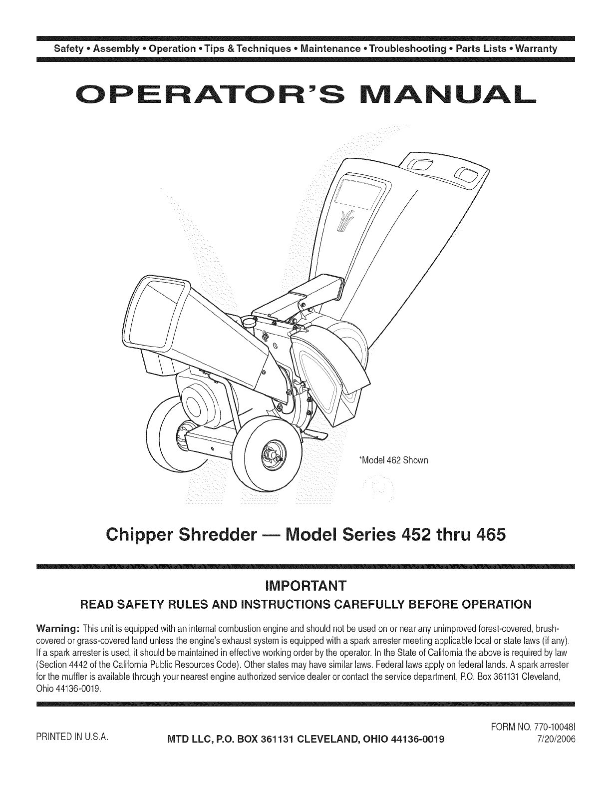
*Model462Shown
Chipper Shredder- Model Series 452 thru 465
IMPORTANT
READ SAFETY RULES AND iNSTRUCTiONS CAREFULLY BEFORE OPERATION
Warning: Thisunit isequippedwithan internalcombustionengineandshouldnot beusedon or nearany unimprovedforest-covered,brush-
coveredor grass-coveredlandunlesstheengine'sexhaustsystemisequippedwitha sparkarrestermeetingapplicablelocalor statelaws(if any).
If a sparkarresterisused,it shouldbemaintainedineffectiveworkingorderby the operator.In theStateof Californiathe aboveisrequiredbylaw
(Section4442of the CaliforniaPublicResourcesCode).Otherstatesmayhavesimilarlaws.Federallawsapplyonfederallands.A sparkarrester
for the muffleris availablethroughyour nearestengineauthorizedservicedealeror contactthe servicedepartment,RO.Box361131Cleveland,
Ohio44136-0019.
PRINTEDIN U.S.A. MTD LLC, P.O. BOX 361131 CLEVELAND, OHIO 44136-0019
FORMNO.770-100481
7/20/2006
This Operator's IVlanual is an important part of your new chipper shredder, it wiil help you assemble, pre=
pare and maintain the unit for best performance. Please read and understand what it says.
Table of Contents
Customer Support .............................................. 2
Safety Labels ...................................................... 3
Safe Operation Practices ................................... 4
Setting UpYour Chipper Shredder .................... 6
Operating Your Chipper Shredder ................... 10
Maintaining Your Chipper Shredder ................ 12
Troubleshooting ................................................ 14
Parts List ........................................................... 16
Warranty ............................................. Back Cover
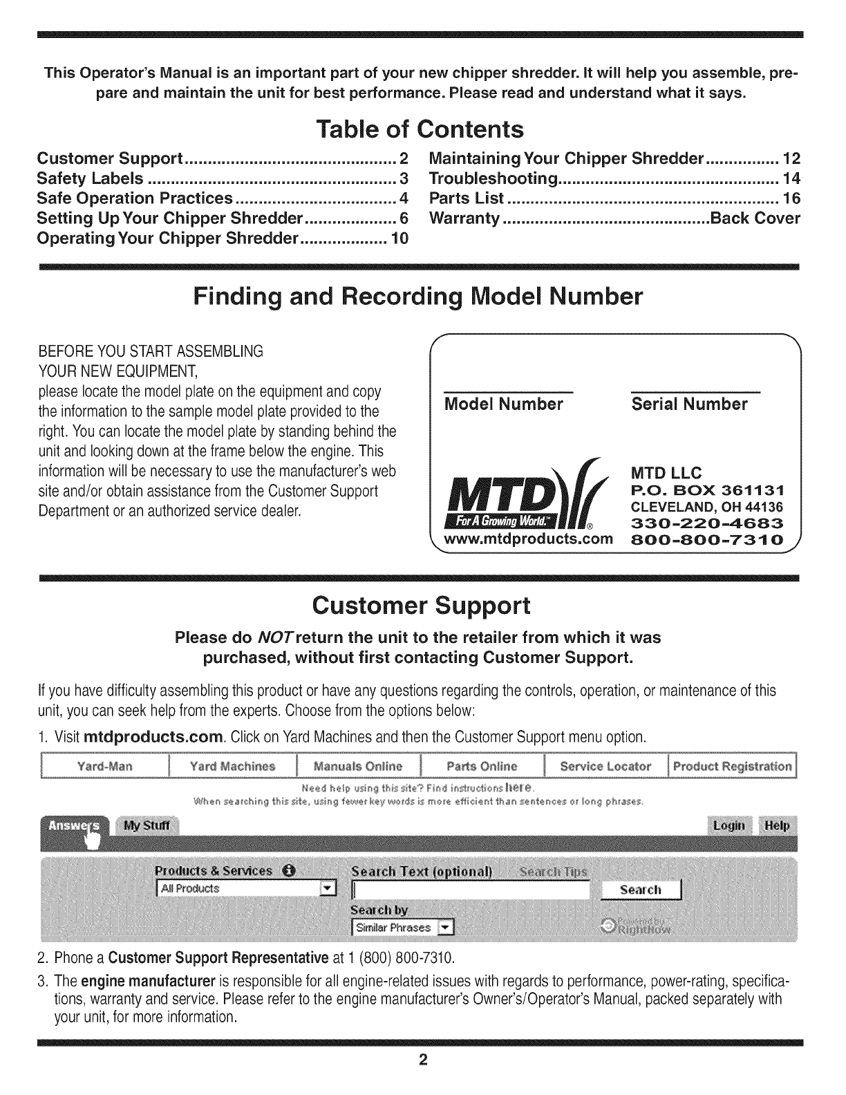
Finding and Recording Model Number
BEFOREYOU STARTASSEMBLING
YOUR NEW EQUIPMENT,
pleaselocate the model plateon the equipment and copy
the informationto the sample model plate providedto the
right. Youcan locatethe model plate by standing behind the
unit and looking down at the frame below the engine. This
informationwill be necessary to use the manufacturer'sweb
site and/or obtain assistance from the Customer Support
Department or an authorizedservice dealer.
f
Model Number
®
www, mtdproducts,com
Serial Number
MTD LLC
P.O. BOX 361131
CLEVELAND, OH 44136
330-220-4683
800-800-7310
Customer Support
Please do NOTreturn the unit to the retailer from which it was
purchased, without first contacting Customer Support.
Ifyou havedifficulty assembling this product or haveany questionsregarding the controls, operation, or maintenanceof this
unit, you can seek helpfrom the experts. Choose from the options below:
1. Visit mtdproducts.com. Click on Yard Machinesand then the CustomerSupport menu option.
2. Phone a Customer Support Representative at 1 (800) 800-7310.
3. The engine manufacturer is responsible for all engine-related issues with regards to performance,power-rating,specifica-
tions, warranty and service. Please refer to the engine manufacturer'sOwner's/Operator's Manual, packedseparately with
your unit,for more information.
2
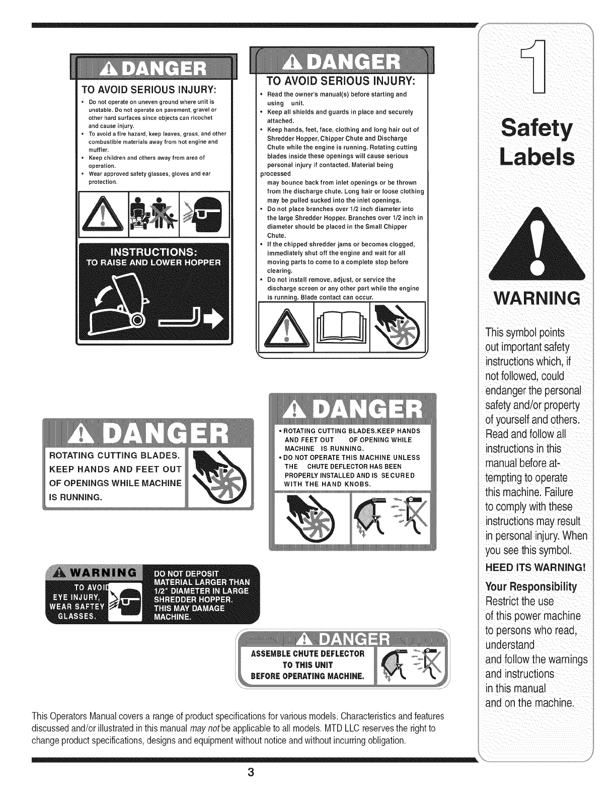
TO AVOID SERIOUS iNJURY:
• Do not operate on uneven ground where unit is
unstable, Do not operate on pavement, gravel or
other hard surfaces since objects can ricochet
and cause injury,
• To avoid a fire hazard, keep leaves, grass, and other
combustible materials away from hot engine and
muffler,
• Keep children and others away from area of
operation,
• Wear approved safety glasses, gloves and ear
protection.
ROTATING CUTTING BLADES.
TO AVOID SERIOUS iNJURY:
• Read the owner's manual(s) before starting and
using unit,
• Keep all shields and guards in place and securely
attached.
• Keep hands, feet, face, clothing and long hair out of
Shredder Hopper, Chipper Chute and Discharge
Chute while the engine is running, Rotating cutting
blades inside these openings will cause serious
personal injury if contacted. Material being
processed
may bounce back from inlet openings or be thrown
from the discharge chute. Long hair or loose clothing
may be pulled sucked into the inlet openings.
• Do not place branches over 1/2 inch diameter into
the large Shredder Hopper. Branches over 1/2 inch in
diameter should be placed in the Small Chipper
Chute.
• If the chipped shredder jams or becomes clogged,
immediately shut off the engine and wait for all
moving parts to come to a complete stop before
clearing.
• Do not install remove, adjust, or service the
discharge screen or any other part while the engine
is running. Blade contact can occur.
JI
KEEP HANDS AND FEET OUT
OF OPENINGS WHILE MACHINE
iS RUNNING.
• ROTATING CUTTING BLADES.KEEP HANDS
AND FEET OUT OF OPENING WHILE
MACHINE IS RUNNING.
• DO NOT OPERATE THIS MACHINE UNLESS
THE CHUTE DEFLECTOR HAS BEEN
PROPERLY INSTALLED AND IS SECURED
WITH THE HAND KNOBS.
ThisOperatorsManualcoversa rangeof productspecificationsfor variousmodels.Characteristicsandfeatures
discussedand/orillustratedinthis manualmaynot beapplicableto all models.MTDLLC reservesthe rightto
changeproductspecifications,designsandequipmentwithoutnoticeandwithoutincurringobligation.
WARNING
This symbolpoints
out importantsafety
instructionswhich, if
not followed,could
endangerthe personal
safetyand/or property
of yourselfandothers.
Readandfollow all
instructionsinthis
manualbeforeat-
temptingto operate
this machine.Failure
to complywiththese
instructionsmay result
in personalinjury.When
you see this symbol.
HEED ITS WARNING!
Your Responsibility
Restrictthe use
of this power machine
to persons who read,
understand
and follow the warnings
and instructions
in this manual
and onthe machine.
3
WARNING
This symbolpoints
out importantsafety
instructionswhich, if
notfollowed,could
endangerthe personal
i safetyand/or property
I ofyourselfand others.
Readandfollow all
instructionsinthis
manualbeforeat-
temptingto operate
i this machine. Failure
I to complywith these
instructionsmay result
i in personalinjury.When
you see this symbol.
i HEED ITS WARNING!
i Your Responsibility
Restrictthe use
of this power machine
to personswho read.
i understand
andfollow the warnings
and instructions
i inthis manual
and on the machine.
WARNING: Engine Exhaust,some of its constituents, andcertain vehicle compo-
nentscontain or emit chemicals knownto State of Californiato cause cancer and
birth defects or other reproductiveharm.
DANGER: This machine was built to be operated according to the rules for safe operation in this
manual.As with any type of power equipment,carelessness or error on the part of the operator can
result in serious injury.This machine is capable of amputating hands andfeet andthrowing objects.
Failureto observethe followingsafety instructionscould result inserious injuryor death.
Training
1. Read,understand,and followall instructionson the ma- 1.
chineandin the manual(s)beforeattemptingto assemble
andoperate.Keepthis manualina safe placefor future
and regularreferenceand for orderingreplacementparts.
2. Befamiliarwith allcontrolsandtheir properoperation. 2.
Knowhowto stopthe machineanddisengagethem
quickly.
3. Neverallow childrenunder 16years oldto operatethis
machine.Children 16years old andovershould readand 3.
understandthe operationinstructionsandsafety rulesin
this manualand shouldbe trainedand supervisedbya
parent.
4. Neverallow adultsto operatethis machinewithoutproper
instruction. 4.
5. Keepbystanders,helpers,pets,and childrenat least
75feetfromthe machinewhile it is in operation.Stop
machineif anyoneentersthe area.
6. Neverrunan engineindoorsor in a poorlyventilatedarea. 5.
Engineexhaustcontainscarbon monoxide,an odorless
anddeadly gas. 6.
7. Do notputhands andfeet nearrotatingparts orin the
feedingchambersanddischargeopening.Contactwith
the rotatingimpellercanamputatefingers,hands,and
feet.
8. Neverattemptto unclogeither thefeed intakeor
dischargeopening,removeor emptybag,or inspectand
repairthe machinewhilethe engineis running.Shutthe
engineoff andwait until all movingpartshavecometo a
completestop. Disconnectthespark plugwire andground
it againsttheengine.
Preparation
Thoroughlyinspectthe areawherethe equipmentisto
beused. Removeall rocks,bottles,cans,or otherforeign
objectswhichcouldbe pickedupor thrown andcause
personalinjuryor damageto the machine.
Alwayswearsafetyglassesor safetygogglesduringopera-
tionor whileperforminganadjustmentor repair,to protect
eyes.Thrownobjectswhich ricochetcancause serious
injuryto the eyes.
Wearsturdy,rough-soledworkshoesand close-fitting
slacksandshirts. Loosefittingclothesor jewelrycan be
caughtin movableparts.Neveroperatethis machine
in barefeet or sandals.Wearleatherworkgloveswhen
feedingmaterialin thechipperchute.
Beforestarting,check allboltsand screwsfor propertight-
nessto be surethe machineisin safeworkingcondition.
Also,visuallyinspectmachinefor any damageat frequent
intervals.
Maintainor replacesafetyandinstructionslabels,as
necessary.
Toavoidpersonalinjuryor propertydamageuseextreme
care inhandlinggasoline.Gasolineis extremelyflammable
andthe vaporsare explosive.Seriouspersonalinjurycan
occurwhengasolineis spilledon yourselforyour clothes
whichcanignite.Washyour skinand changeclothes
immediately.
a. Useonly an approvedgasolinecontainer.
b. Extinguishallcigarettes,cigars, pipes,andother
sourcesof ignition.
c. Neverfuel machineindoors.
d. Neverremovegas cap oradd fuelwhilethe engineis hot
or running.
e. Allowengineto coolat leasttwo minutesbeforerefuel-
ing.
f. Neveroverfill fuel tank. Filltankto nomorethan 1/2
inch belowbottomof filler neckto providespacefor fuel
expansion.
g. Replacegasolinecap andtightensecurely.
h. If gasolineis spilled,wipe itoff theengineand equip-
ment.Movemachineto anotherarea.Wait 5 minutes
beforestartingtheengine.
i. Neverstorethe machineorfuel containerinside where
there isan openflame, spark,or pilot light (e.g.furnace,
waterheater,spaceheater,clothesdryer,etc.)
j. Toreducea fire hazard,keepmachinefree of grass,
leaves,or otherdebris build-up.Cleanupoilor fuel
spillageand removeanyfuel soakeddebris.
k. Allowmachineto cool at least5 minutesbeforestoring.
4
Operation
1. Donot puthandsandfeet nearrotatingpartsor in the
feedingchambersand dischargeopening.Contactwith the
rotatingimpellercanamputatefingers, hands,andfeet.
2. Beforestartingthe machine,makesurethe chipperchute,
feed intake,and cuttingchamberare empty andfree of all
debris.
3. Thoroughlyinspectall materialto beshreddedand remove
any metal,rocks,bottles,cans,orotherforeignobjects
which could causepersonalinjury or damageto the
machine.
4. f it becomesnecessaryto pushmaterialthroughthe
shredderhopper,usea smalldiameterstick. Do notuse
your hands orfeet.
5. f the impellerstrikesa foreignobject or ifyour machine
should start makingan unusualnoiseor vibration,
immediatelyshuttheengine off.Allow the impellerto come
to a completestop.Disconnectthe sparkplugwire,ground
itagainstthe engineandperformthe followingsteps:
a. Inspectfor damage.
b. Repairorreplaceanydamagedparts.
c. Checkfor anyloosepartsand tightento assure
continuedsafeoperation.
6. Donotallow an accumulationof processedmaterialto build
upinthe dischargearea.Thiscan preventproperdischarge
and result in kickbackof materialthroughthefeed opening.
7. Donotattemptto shredorchip materiallargerthan
specifiedon the machineor inthis manual.Personalinjury
or machinedamagecouldresult.
8. Neverattemptto unclogeitherthe feed intakeordischarge
openingwhilethe engineisrunning.Shutthe engineoff,
wait until all movingparts havestopped,disconnectthe
spark plugwire andground it againsttheenginebefore
clearingdebris.
9. Neveroperatewithoutthe shredderhopper,chipperchute,
or chute deflectorproperlyattachedto the machine.Never
emptyor changedischargebagwhiletheengineis running.
10.Keepall guards,deflectorsand safetydevicesin placeand
operatingproperly.
11.Keepyourface andbody backand to theside ofthe chipper
chute whilefeedingmaterialintothe machineto avoid
accidentalkickbackinjuries.
12.Neveroperatethis machinewithoutgoodvisibility or light.
13.Donotoperatethis machineon a paved,gravelor non-level
surface.
14.Donotoperatethis machinewhile underthe influenceof
alcohol ordrugs.
15.Mufflerandenginebecomehotandcan causea burn.Do
nottouch.
16.Neverpickupor carrymachinewhilethe engineisrunning.
Maintenance & Storage
1. Nevertamper withsafetydevices.Checktheir proper
operationregularly.
2. Checkbolts and screwsfor propertightnessat frequent
intervalsto keepthe machinein safeworkingcondition.
Also,visuallyinspectmachinefor anydamageand repair,if
needed.
3. Beforecleaning,repairing,or inspecting,stopthe engine
andmakecertainthe impellerand all movingparts have
stopped.Disconnectthe sparkplug wire and groundit
againsttheengineto preventunintendedstarting.
4. Do notchangethe enginegovernorsettingsor overspeed
theengine.The governorcontrolsthemaximumsafe
operatingspeed of theengine.
5. Maintainor replacesafetyandinstructionlabels,as neces-
sary.
6. Followthis manualforsafe loading,unloading,transporting,
andstorageof this machine.
7. Neverstorethe machineorfuel containerinside where
thereisan openflame, sparkor pilot lightsuch as a water
heater,furnace,clothesdryer,etc.
8. Alwaysreferto theoperator'smanualfor properinstructions
onoff-seasonstorage.
9. If thefuel tank hasto bedrained,dothis outdoors.
10.Observeproperdisposallawsandregulationsfor gas,oil,
etc. to protectthe environment.
Do not modify engine
Toavoidseriousinjuryordeath,do not modifyengineinany
way.Tamperingwiththegovernorsettingcan leadto a runaway
engineandcauseit to operateat unsafespeeds.Nevertamper
withfactorysettingof enginegovernor.
Notice regarding Emissions
Engineswhichare certifiedto complywithCaliforniaandfederal
EPAemissionregulationsfor SORE(SmallOff RoadEquipment)
arecertified to operateon regularunleadedgasoline,and may
includethefollowingemissioncontrolsystems:EngineModifica-
tion(EM)andThreeWayCatalyst(TWO)ifso equipped.
Your Responsibility
Restrictthe useof this powermachineto personswho read,un-
derstandand followthe warningsand instructionsin this manual
andon the machine.
Practices
WARNING
This symbol points
out importantsafety
instructions, which if
not followed,could
endanger the personal
safety and/or property
of yourself and others.
Readand follow all
instructions inthis man-
ual before attempting to
operate this machine.
Failureto comply with
these instructionsmay
result in personal injury.
When you see this
symbol.
HEED iT S WARNING!
Your Responsibility
Restrictthe use
of this power machine
to personswho read.
understand
and followthe warnings
and instructions
in this manua
and on the machine.
5
Shredder
IMPORTANT
This unit is shipped
without gasoline or
oil in the engine.Be
certainto service
enginewith gasoline
andoil as instructed
in the separateengine
manual before operat-
ing your machine.
NOTE: All references
in this manualto the
left or right side of
the chipper shredder
is from the operating
i position only. Excep-
tions if any will be
specified.
NOTE: This Operators
i Manual covers a range
of product specifica-
tions for various
models. Characteristics
and featuresdiscussed
and/or illustratedinthis
manualmay not be ap-
plicableto all models.
MTD LLC reserves the
right to change product
specifications,designs
and equipmentwithout
notice andwithout
=ncurringobligation.
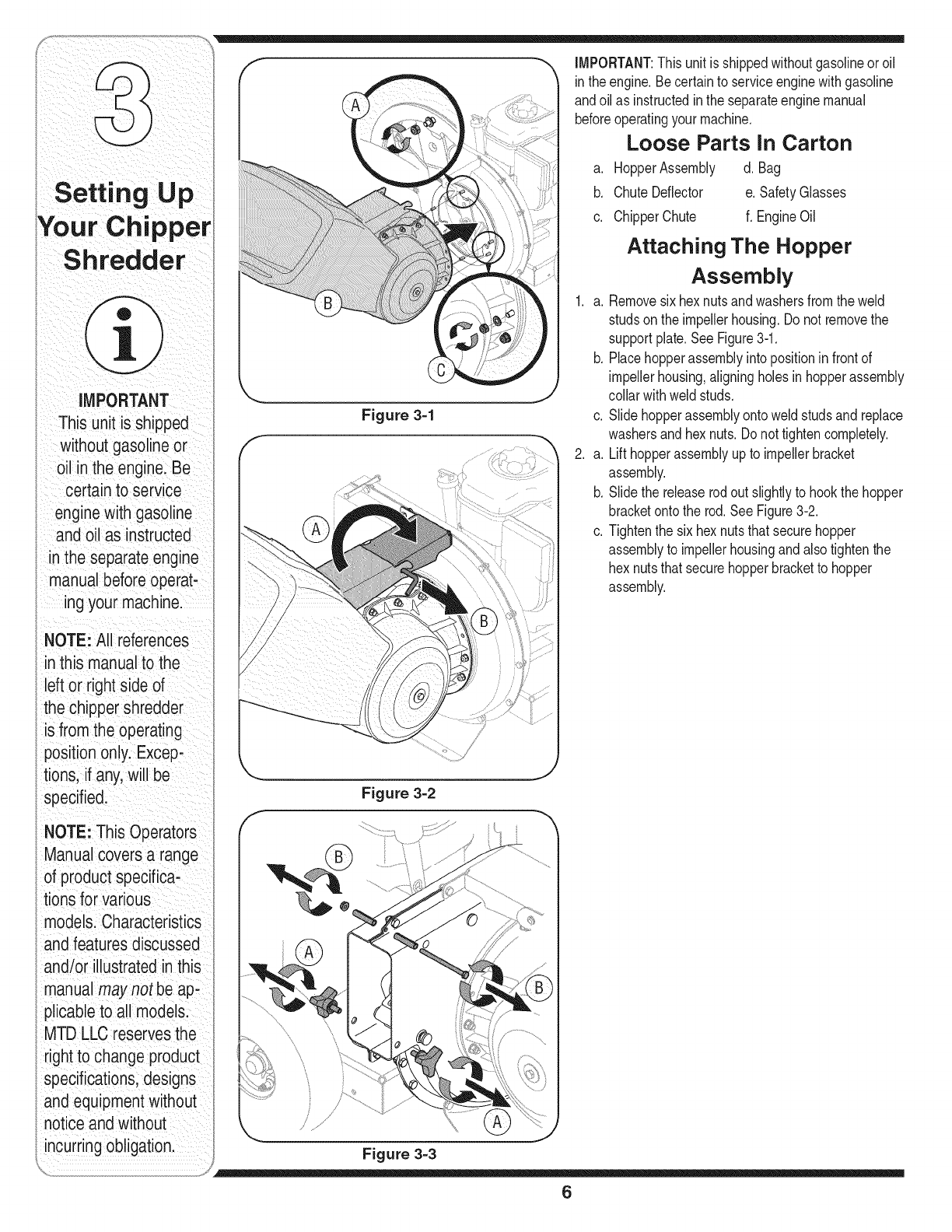
Figure 3=1
IMPORTANT:Thisunit is shippedwithoutgasolineoroil
in theengine.Becertainto serviceenginewithgasoline
andoilas instructedinthe separateenginemanual
beforeoperatingyour machine.
Loose Parts In Carton
a. HopperAssembly d. Bag
b. ChuteDeflector e. SafetyGlasses
c. ChipperChute f. EngineOil
Attaching The Hopper
Assembly
1. a. Removesix hexnutsandwashersfromthe weld
studsonthe impellerhousing.Donot removethe
supportplate.SeeFigure3-1.
b. Placehopperassemblyinto positioninfrontof
impellerhousing,aligningholesinhopperassembly
collarwithweldstuds.
c. Slidehopperassemblyontoweld studsand replace
washersandhex nuts.Donot tightencompletely.
2. a. Lift hopperassemblyupto impellerbracket
assembly.
b. Slidethe releaserodout slightlyto hookthe hopper
bracketontothe rod.SeeFigure3-2.
c. Tightenthe sixhexnutsthatsecurehopper
assemblyto impellerhousingandalsotightenthe
hex nutsthatsecurehopperbracketto hopper
assembly.
Figure 3-2
Figure 3-3
6
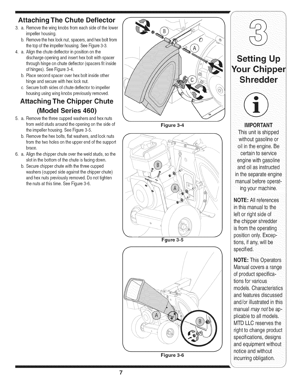
Attaching The Chute Deflector
3. a. Removethe wingknobsfromeach sideof the lower
impellerhousing.
b. Removethe hexlocknut,spacers,andhex boltfrom
the topof theimpellerhousing.SeeFigure3-3.
4. a. Alignthe chutedeflectorinpositionon the
dischargeopeningand inserthex boltwithspacer
throughhingeon chutedeflector(spacersfit inside
of hinges).SeeFigure314.
b. Placesecondspaceroverhex bolt insideother
hingeandsecurewithhex locknut.
c. Securebothsidesof chutedeflectorto impeller
housingusingwingknobspreviouslyremoved.
Attaching The Chipper Chute
(Model Series 460)
5. a. Removethe threecuppedwashersand hexnuts
fromweldstudsaroundthe openingonthe side of
the impellerhousing.SeeFigure3-5.
b. Removethe hexbolts,flat washers,andlocknuts
fromthe twoholeson the upperendof the support
brace.
6. a. Alignthe chipperchuteoverthe weldstuds,sothe
slotinthe bottomof the chuteis facingdown.
b. Securechipperchutewiththe threecupped
washers(cuppedsideagainstthe chipperchute)
and hexnutspreviouslyremoved.Do nottighten
the nutsat thistime. SeeFigure316.
Figure 3-4
f
Fgure 3=5
/
//
/ /
/
//
/
/
..........1,/
/
/J
/
/
/
//
/
/
Figure 3=6
Your Chipper
Sh redder
IMPORTANT
This unit is shipped
without gasolineor
oil in the engine. Be
certain to service
enginewith gasoline
and oil as instructed
in the separate engine
manual before operat-
ing your machine.
NOTE: All references
in this manualto the
left or right side of
the chipper shredder
is from the operating
positiononly. Excep-
tions, if any, will be
specified.
NOTE: This Operators
Manual covers a range
of product specifica-
tions for various
models. Characteristics
andfeatures discussed
and/or illustrated inthis
manual may not be ap-
plicableto all models.
MTD LLC reservesthe
right to change product
specifications,designs
and equipmentwithout
notice andwithout
_ncurringobligation.
7
Setting up
MPORTANT
This unitis shipped
without gasoline or
oil in the enginelae
certain to serv ce
engine with gasoline
an_Joil as instructed
in the separateengine
manUaIbeforeope!at-
ing your machine
NOTE: All references
in this manual tOthe
left or right side of
the chipper shredder
iSfrom the operating
positiononlylExcep;
tions, if any, w Ii be
specified:
i
NOTE: This Operators
ManUalcovers a range
Of product specifiCa:
tions for Various
mode!s:Characteristics
and featuresdiscussed
andior ilUstratedinthiS
manual may not be ap,
plicable toali models!
MTD LLC reservesthe
right to change product
specificationsidesigns
andequipment w thout
notice and without
incurring obligationl
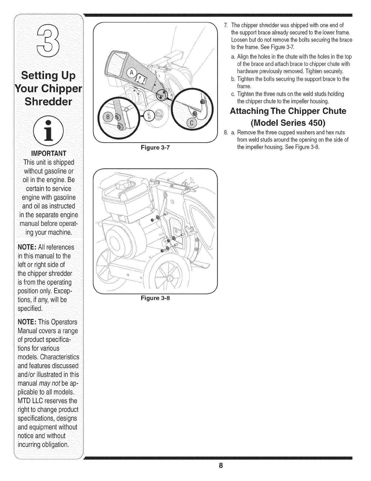
Figure 3-7
/
/
/
/
ji
//
// ///
//
/
7. Thechippershredderwasshippedwithoneendof
the supportbracealreadysecuredto the lowerframe.
Loosenbut do not removetheboltssecuringthe brace
to the frame.See Figure3-7.
a. Alignthe holesinthe chutewiththe holes inthe top
of the braceandattachbraceto chipperchutewith
hardwarepreviouslyremoved.Tightensecurely.
b. Tightenthe boltssecuringthe supportbraceto the
frame.
c. Tightenthe three nutson the weldstudsholding
the chipperchuteto the impellerhousing.
Attaching The Chipper Chute
(Model Series 450)
8. a. Removethethreecuppedwashersandhex nuts
fromweld studsaroundtheopeningon the sideof
the impellerhousing.SeeFigure3-8.
Figure 3=8
8
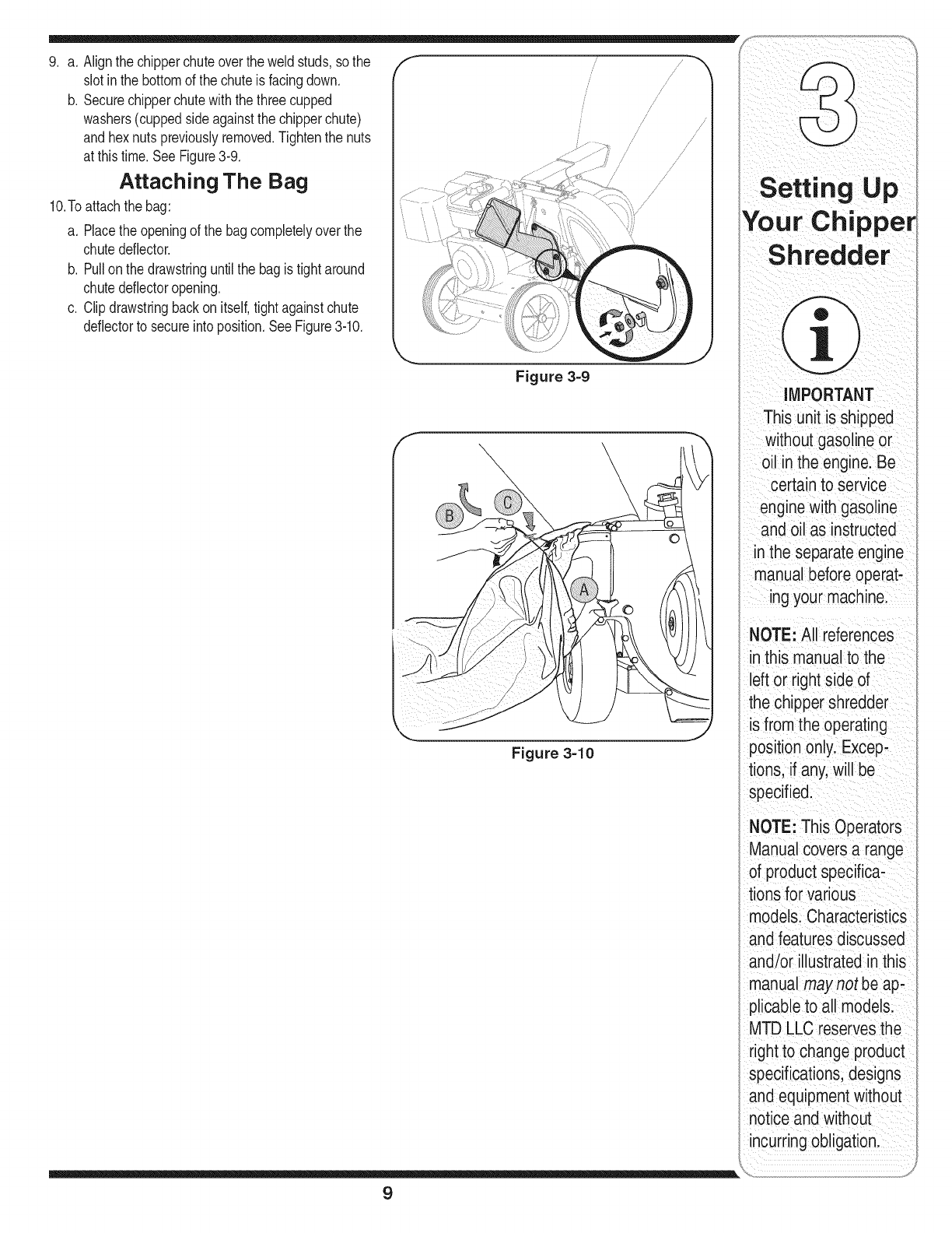
Figure 3=9
Figure 3=10
f
/
/
9. a. Alignthe chipperchuteoverthe weldstuds,sothe
slotinthe bottomof the chuteis facingdown.
b. Securechipperchutewiththe threecupped
washers(cuppedsideagainstthe chipperchute)
and hexnutspreviouslyremoved.Tightenthe nuts
at this time.SeeFigure3-9.
Attaching The Bag
10.Toattachthe bag:
a. Placethe openingof the bagcompletelyover the
chutedeflector.
b. Pullon the drawstringuntilthe bagis tightaround
chutedeflectoropening.
c. Clipdrawstringbackon itself,tightagainstchute
deflectorto secureintoposition.SeeFigure3-10.
Setting Up
YourChippe
Shredder
MPORTANT
This unit iSshipped
without gaso ine or
oilin the enginelBe
Certain to service
engine with gasoline
and Oilas instrUCted
the separate engine
manualbefore operati
ing your machine:
NOTE: All references
this manual tothe
left or right side of
the chipper shredder
is from the operating
position only. Excepi
tions, if any.will be
specified:
NOTE: This OPerators
ManUal covers a range
of product specifiCa,
tions for Various
models: CharacteriStics
andfeatures discussed
and/or iilustrated inthis
manual may notbe ap.
plicable to all models:
MTD LLC reservesthe
right to Changeproduct
specifications; designs
and equipmentwithout
notice and w thout
incurr ng Obligationl
9
WARNING
The operation of any
chipper shredder
can result inforeign
objects being thrown
intothe eyes, which
can damageyour
Ieyes severely. Always
iwear the safety
glasses provided
with this unit or eye
ishields before chip-
ping or shredding
and while performing
iany adjustments or
repairs.
I Use extreme care
when handling
gasoline. Gasoline is
extremely flammable
i and the vapors are
explosive. Neverfuel
i the machine indoors
'or while the engine
is hot or running.
I Extinguish cigarettes,
cigars, pipes and
other sources of
ignition.
m
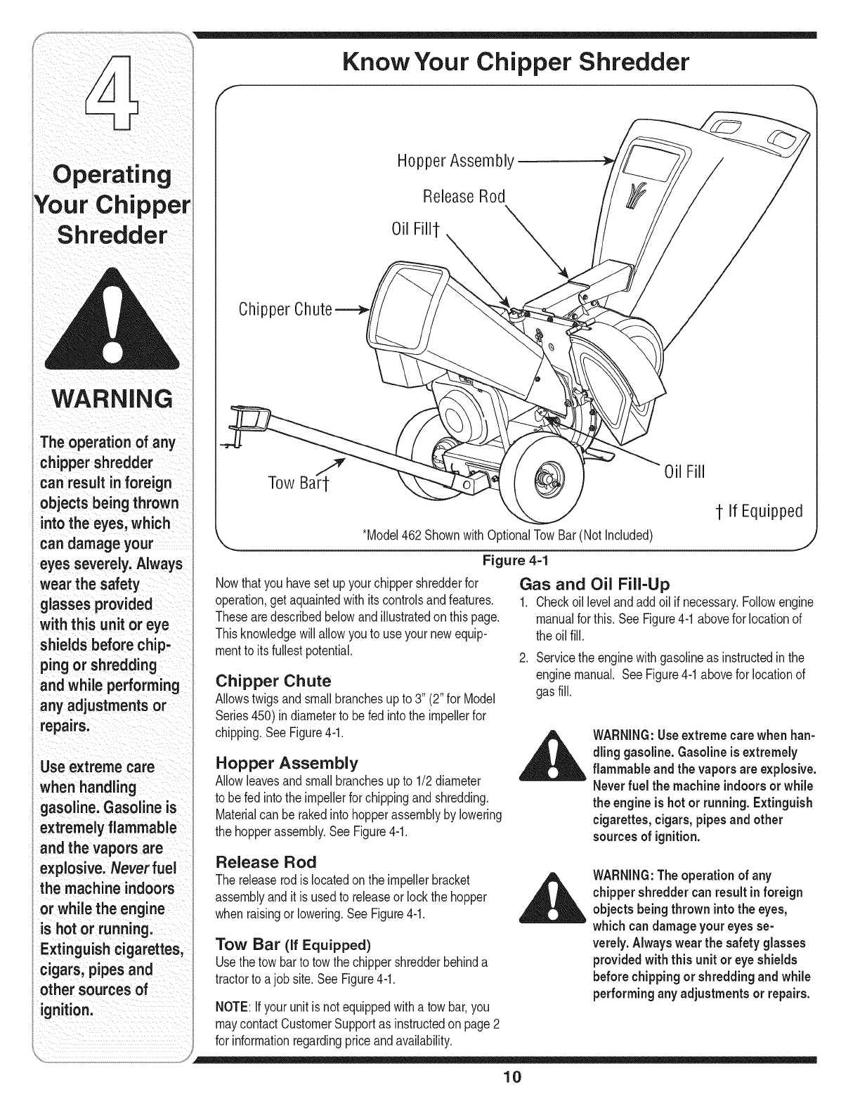
Know Your Chipper Shredder
HopperAssembly
ReleaseRod
Oil Fillt
Chipper Chute
Oil Fill
1 If Equipped
*Model462 Shownwith0 (Notincluded)
Figure 4-1
Nowthatyou havesetupyour chippershredderfor
operation,get aquaintedwithits controlsandfeatures.
Thesearedescribedbelowandillustratedonthis page.
Thisknowledgewillallowyou to use yournewequip-
mentto itsfullestpotential.
Chipper Chute
Allowstwigsandsmall branchesup to 3" (2"for Model
Series450)indiameterto befed intothe impellerfor
chipping.SeeFigure4-1.
Hopper Assembly
Allowleavesandsmallbranchesupto 1/2diameter
to befed into theimpellerforchippingandshredding.
Materialcan be rakedinto hopperassemblyby lowering
the hopperassembly.SeeFigure4-1.
Gas and Oil Fill-Up
1. Checkoillevelandaddoil if necessary.Followengine
manualfor this. SeeFigure4-1abovefor locationof
the oilfill.
2. Servicethe enginewithgasolineas instructedinthe
enginemanual. SeeFigure4-1abovefor locationof
gasfill.
WARNING:Useextremecarewhenhan-
dling gasoline.Gasoline is extremely
flammable and the vapors areexplosive.
Neverfuel the machine indoorsor while
the engineis hot or running.Extinguish
cigarettes, cigars, pipesand other
sources of ignition.
Release Rod
The releaserodis locatedon the impellerbracket
assemblyandit is usedto releaseor lockthe hopper
whenraisingor lowering.See Figure4-1.
Tow Bar (if Equipped)
Usethetow barto towthe chippershredderbehinda
tractorto ajobsite.See Figure4-1.
NOTE:Ifyour unit isnotequippedwitha towbar,you
maycontactCustomerSupportas instructedon page2
for informationregardingpriceandavailability.
WARNING:Theoperation of any
chippershredder canresultinforeign
objects being thrown intothe eyes,
which can damage your eyesse-
verely. Always wear the safety glasses
providedwith this unit or eye shields
before chippingor shredding andwhile
performingany adjustments or repairs.
10
ThisOperatorsManualcoversa rangeof product f _ -=]
specificationsforvariousmodels.Characteristicsandfea- _ /, |
turesdiscussedand/or illustratedinthismanualmaynot _ _ |
be applicableto allmodels.MTDLLCreservesthe right ._1__ _11111_
to changeproductspecifications,designsandequipment _
withoutnoticeandwithoutincurringobligation.
Starting Engine (
WARNING:Neverrun the engine
indoorsor in apoorlyventilatedarea.
Engine exhaustcontainscarbonmonox-
ide,an odorless and deadly gas.
IMPORTANT:Becausethismanualcoversseveral
differentmodelunits,differentstartinginstructionsmay
applyto your particularengine.Someenginesmayhave
a fuel petcock,somemaynot.Someenginesmayhave
On/Off switches,othermaynot.Someunitswill utilizea
chokesystem,whileotherswill requirepriming. These
factorsdependon whatmakeandmodelenginecomes
withyour particularunit.For thesereasons,pleaserefer
to the engineoperator'smanualforthe correctstarting
procedure.
1. Attachsparkplugwire to sparkplug.Makecertain
the metalcap on theend of the sparkplugisfastened
securelyoverthe metaltip onthe sparkplug.
2. Engines with choke lever:
Movechokeleveronengineto CHOKEposition.(A
warmenginemaynot requirechoking).
Engines withprimer:
Primeengineas instructedinseparateenginemanual.
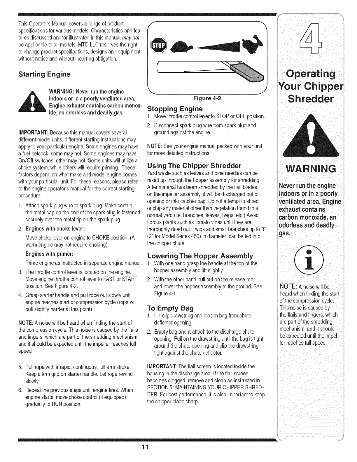
3. The throttlecontrolleveris locatedonthe engine.
Moveenginethrottlecontrolleverto FASTor START
position.SeeFigure4-2.
4. Graspstarterhandleand pullropeout slowlyuntil
enginereachesstart of compressioncycle(ropewill
pull slightlyharderat this point).
NOTE:A noisewill beheardwhenfindingthe start of
the compressioncycle.Thisnoiseis causedby theflails
andfingers,whichare partof the shreddingmechanism,
and it shouldbeexpecteduntilthe impellerreachesfull
speed.
5. Pullropewitha rapid,continuous,fullarm stroke.
Keepa firmgriponstarterhandle.Let roperewind
slowly.
6. Repeatthe previousstepsuntilenginefires.When
enginestarts,movechokecontrol(if equipped)
graduallyto RUNposition.
Figure 4=2
Stopping Engine
1. Movethrottlecontrolleverto STOPor OFFposition.
2. Disconnectsparkplugwirefromsparkplugand
groundagainstthe engine.
NOTE:Seeyourenginemanualpackedwithyour unit
for moredetailedinstructions.
Using The Chipper Shredder
Yardwastesuchas leavesandpineneedlescan be
rakedupthroughthe hopperassemblyfor shredding.
Aftermaterialhas beenshreddedbythe flail blades
onthe impellerassembly,itwill bedischargedout of
openingor into catcherbag. Donot attemptto shred
orchip anymaterialotherthanvegetationfoundina
normalyard (i.e.branches,leaves,twigs,etc.)Avoid
fibrousplantssuchas tomatovinesuntil theyare
thoroughlydriedout. Twigsandsmallbranchesupto 3"
(2" for ModelSeries450) indiameter can befed into
the chipperchute.
Lowering The Hopper Assembly
1. Withonehandgraspthe handleat the top of the
hopperassemblyandlift slightly.
2. Withtheother handpullout onthe releaserod
andlowerthe hopperassemblyto the ground.See
Figure4-1.
To Empty Bag
1. Un-clipdrawstringand loosenbagfromchute
deflectoropening.
2. Emptybagandreattachto the dischargechute
opening.Pullonthe drawstringuntilthe bagistight
aroundthe chuteopeningandclip thedrawstring
tightagainstthechutedeflector.
IMPORTANT:The flailscreenislocatedinsidethe
housingin the dischargearea.If theflail screen
becomesclogged,removeandcleanas instructedin
SECTION5: MAINTAININGYOURCHIPPERSHRED-
DER.Forbestperformance,it isalso importantto keep
the chipperbladesharp.
Never run the engine
indoorsorin apoorly
ventilated area: Engine
exhaust contains
carbon monoxide, an
)dorless and deadly
NOTE:A noisewill be
heardwhenfindingthestart
ofthe compressioncycle.
Thisnoiseis causedby
theflailsandfingers,which
arepart ofthe shredding
mechanism,andit should
beexpecteduntilthe impel-
er reachesfull speed.
11
Your Chipper
Shredder
Always stop engine,
disconnectspark
plug, and ground
against engine
before cleaning,
lubricatingor
doing any kindof
maintenance on your
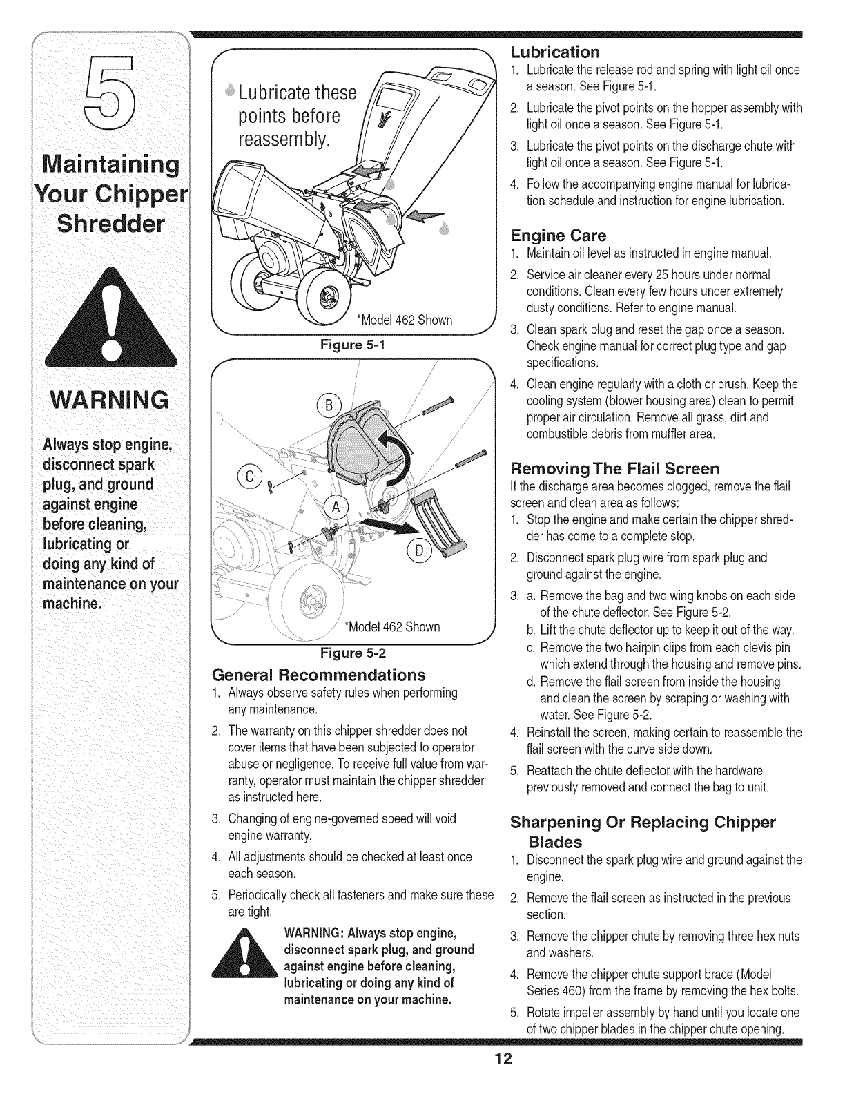
machine.
points before
reassembly.
*Model462Shown
Figure 5-1
;//
/*Model462 Shown
Figure 5-2
General Recommendations
1. Alwaysobservesafetyruleswhen performing
anymaintenance.
2. Thewarrantyon thischippershredderdoes not
coveritemsthathavebeensubjectedto operator
abuseornegligence.Toreceivefull valuefromwar-
ranty,operatormustmaintainthe chippershredder
as instructedhere.
3. Changingof engine-governedspeedwill void
enginewarranty.
4. Alladjustmentsshouldbecheckedat leastonce
eachseason.
5. Periodicallycheckallfastenersand makesurethese
aretight.
_ WARNING:Alwaysstopengine,
disconnectsparkplug, and ground
against enginebefore cleaning,
lubricating or doingany kind of
maintenanceon your machine.
Lubrication
1. Lubricatethe releaserodand springwithlightoil once
a season.SeeFigure5-1.
2. Lubricatethe pivotpointsonthe hopperassemblywith
lightoil oncea season.See Figure5-1.
3. Lubricatethe pivotpointsonthe dischargechutewith
lightoil oncea season.See Figure5-1.
4. Followtheaccompanyingenginemanualfor lubrica-
tion scheduleandinstructionfor enginelubrication.
Engine Care
1. Maintainoil levelas instructedin enginemanual.
2. Serviceaircleanerevery25 hoursundernormal
conditions.Cleaneveryfewhoursunderextremely
dustyconditions.Referto enginemanual.
3. Cleansparkplugand resetthegaponce a season.
Checkenginemanualfor correctplugtype andgap
specifications.
4. Cleanengineregularlywitha clothorbrush.Keepthe
coolingsystem(blowerhousingarea)cleanto permit
properaircirculation.Removeall grass,dirt and
combustibledebrisfrommufflerarea.
Removing The Flail Screen
If the dischargeareabecomesclogged,removetheflail
screenandcleanareaas follows:
1. Stopthe engineandmakecertainthe chippershred-
derhas cometo a completestop.
2. Disconnectsparkplugwirefromsparkplugand
groundagainsttheengine.
3. a. Removethe bagandtwo wingknobson eachside
of the chutedeflector.See Figure5-2.
b. Liftthe chutedeflectorupto keepitoutof theway.
c. Removethetwo hairpinclipsfromeach clevispin
whichextendthroughthe housingandremovepins.
d. Removetheflail screenfrominsidethe housing
andcleanthe screenby scrapingor washingwith
water.SeeFigure5-2.
4. Reinstallthe screen,makingcertainto reassemblethe
flail screenwiththecurvesidedown.
5. Reattachthe chutedeflectorwiththe hardware
previouslyremovedandconnectthe bagto unit.
Sharpening Or Replacing Chipper
Blades
1. Disconnectthe sparkplugwire andgroundagainstthe
engine.
2. Removetheflail screenas instructedinthe previous
section.
3. Removethechipperchuteby removingthree hexnuts
andwashers.
4. Removethechipperchutesupportbrace(Model
Series460)fromthe frame by removingthe hexbolts.
5. Rotateimpellerassemblyby handuntilyoulocateone
of twochipperbladesinthe chipperchuteopening.
12
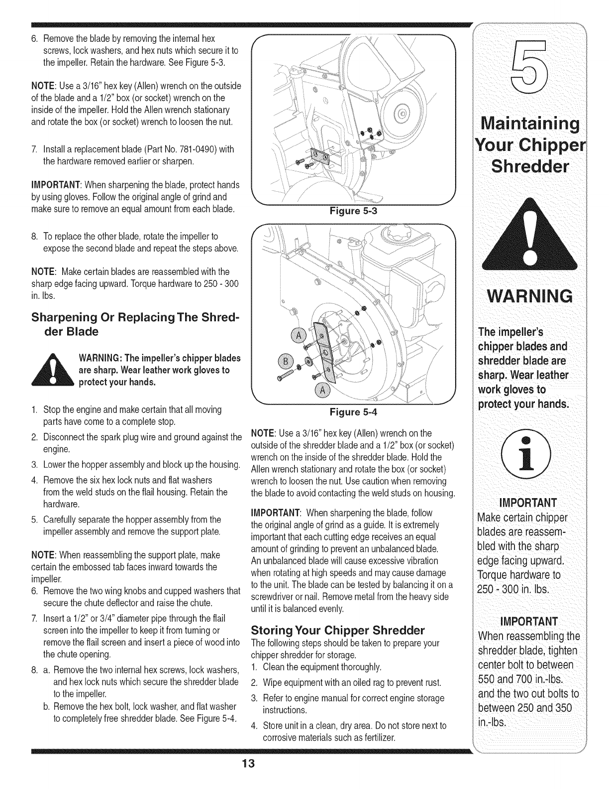
6. Removethe bladeby removingthe internalhex
screws,lockwashers,andhexnutswhichsecureit to
the impeller.Retainthe hardware.SeeFigure5-3.
NOTE: Usea 3/16"hex key(Allen)wrenchonthe outside
of the bladeanda 1/2" box(or socket)wrenchonthe
insideof the impeller.HoldtheAllenwrenchstationary
and rotatethe box(or socket)wrenchto loosenthe nut.
7. Installa replacementblade(PartNo.781-0490)with
the hardwareremovedearlieror sharpen.
IMPORTANT:Whensharpeningthe blade,protecthands
by usinggloves.Followthe originalangleof grindand
makesureto removean equalamountfromeachblade. Figure 5-3
8. To replacethe otherblade,rotatethe impellerto
exposethe secondbladeandrepeatthe stepsabove.
NOTE: Makecertainbladesarereassembledwiththe
sharpedgefacingupward.Torquehardwareto 250- 300
in. Ibs.
Sharpening Or Replacing The Shred-
der Blade
_ARNING:Theimpeller'schipperblades
are sharp. Wearleatherwork gloves to
protectyour hands.
1. Stop theengineand makecertainthatall moving
partshavecometo acompletestop.
2. Disconnectthe sparkplugwireandgroundagainstthe
engine.
3. Lowerthe hopperassemblyandblockupthe housing.
4. Removethe sixhex locknutsandflatwashers
fromthe weldstudson theflail housing.Retainthe
hardware.
5. Carefullyseparatethe hopperassemblyfromthe
impellerassemblyandremovethe supportplate.
NOTE:When reassemblingthe supportplate,make
certaintheembossedtab facesinwardtowardsthe
impeller.
6. Removethe twowing knobsandcuppedwashersthat
securethe chutedeflectorandraisethe chute.
7. Inserta 1/2"or 3/4" diameterpipethroughthe flail
screenintothe impellerto keepit fromturningor
removethe flail screenand inserta pieceof wood into
the chuteopening.
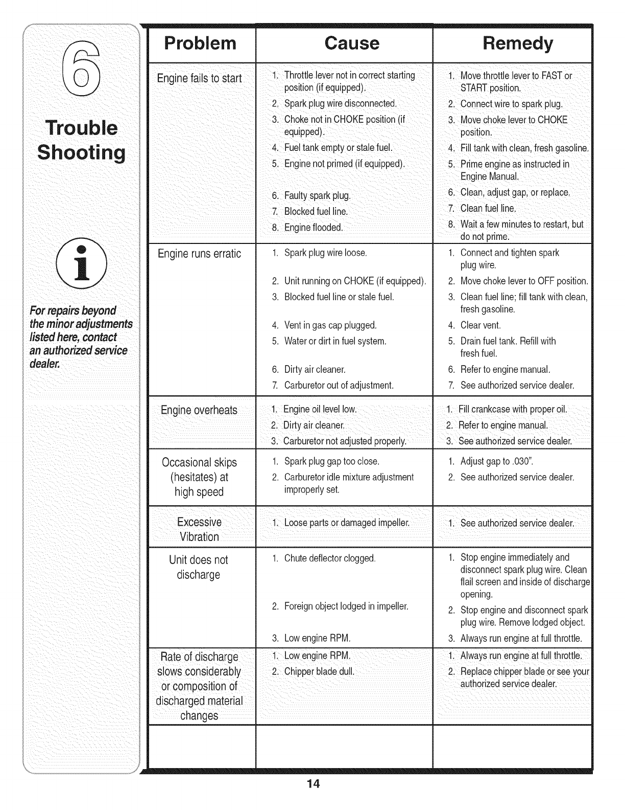
8. a. Removethe twointernalhex screws,lockwashers,
and hexlocknutswhichsecurethe shredderblade
to the impeller.
b. Removethe hexbolt,lockwasher,andflatwasher
to completelyfree shredderblade.See Figure5-4.
Figure 5-4
NOTE:Usea3/16"hexkey(Allen)wrenchon the
outsideof the shredderbladeanda 1/2" box(orsocket)
wrenchonthe insideof the shredderblade.Holdthe
Allenwrenchstationaryandrotatethe box (orsocket)
wrenchto loosenthenut. Usecautionwhen removing
the bladeto avoidcontactingthe weldstudson housing.
IMPORTANT:Whensharpeningthe blade,follow
the originalangleof grindas a guide.It is extremely
importantthateachcuttingedgereceivesanequal
amountof grindingto preventan unbalancedblade.
Anunbalancedbladewill causeexcessivevibration
whenrotatingat highspeedsandmaycausedamage
to the unit.Thebladecan betestedby balancingit on a
screwdriveror nail. Removemetalfromthe heavyside
until it is balancedevenly.
Storing Your Chipper Shredder
Thefollowingstepsshouldbetakento prepareyour
chippershredderfor storage.
1. Cleantheequipmentthoroughly.
2. Wipeequipmentwithanoiled ragto preventrust.
3. Referto enginemanualforcorrectenginestorage
instructions.
4. Storeunitin a clean,dry area. Donot storenextto
corrosivematerialssuchas fertilizer.
13
Your Chipper
i
,redder
WARi ,,ING
The impeller S
chipper blades and
shredder blade are
sharp: Wear leather
work gloves to
protect your hands;
IMPORTANT
Makecertainchipper
blades are reassem:
bled with the sharp
edge facing upwar&
Torquehardwareto
250,300 in.Ibs.
iMPORTANT
When reasSemblingthe
shredderblade,tighten
center bolt tObetween
550 and 700ini,lb&
andthe twoOutboltsto
between 250 and350
in.4b&
For repairs beyond
the minor adjustments
listed here, contact
an authorized service
Problem Cause Remedy
Enainef., ailsto Start I Throttle levernotin correctStarting i Movethrott, e everto FASTor
post on (f equpped) STARTpost on
2, Sparkp!ugwire disconnected, 2, Connectwire tosparkp!ug,
chokenotincHoKEposition(if cHOKE
equipped): poSiti0nl
FueltankemptyorSta!efuel. tankwithclean,freShgasolinel
&Engine not pdmed(if equipped)Prime engineas .instructedin
6 Faut ark _ 6 ceanadjuStgap 0rrepace
ysp P g: !
Blockedfuel CleanfueI
81Engine flooded, &Wait afew minutesto Festart,but
do not prme:
.
2.
3.
4.
5.
Engineruns erratic Sparkplugwireloose.
UnitrunningonCHOKE(if equipped).
Blockedfuellineor stalefuel.
Ventingas cap plugged.
Waterordirt infuel system.
6. Dirty aircleaner.
7. Carburetorout of adjustment.
1. Connectandtightenspark
plugwire.
2. Movechokeleverto OFFposition.
3. Cleanfuel line;fill tankwithclean,
freshgasoline.
4. Clearvent.
5. Drainfuel tank. Refillwith
freshfuel.
6. Referto enginemanual.
7. Seeauthorizedservicedealer.
Engine overheats 1. Engineoil levellow. _ 1. Fillcrankcasewithproperoil.
2. Dirty aircleaner. I 2. Referto enginemanual,
• 3. Carburetornotadjustedproperly.
Occasionalskips
(hesitates)at
high speed
Unit does not
discharge
1. Sparkpluggaptooclose.
2. Carburetoridlemixtureadjustment
improperlyset.
1. Chutedeflectorclogged.
2. Foreignobjectlodgedin impeller.
3. LowengineRPM.
3. Seeauthorizedservicedealer.
1. Adjustgap to .030".
2. Seeauthorizedservicedealer.
1. Stop engineimmediatelyand
disconnectsparkplugwire.Clean
flail screenandinsideof discharge
opening.
2. Stop engineanddisconnectspark
plugwire.Removelodgedobject.
3. Alwaysrunengineat full throttle.
Rate of discharge 1 LowengineRPM. 1. Alwaysrunengineat fullthrottle.
slows considerably I 2. Chipperbladedul. I 2. Replacechipperbladeor seeyour
or composition of authorzed servcedeaer.
discharged material I I
changes ,
14

NOTES
Use this page to make notes and write down important information.
15
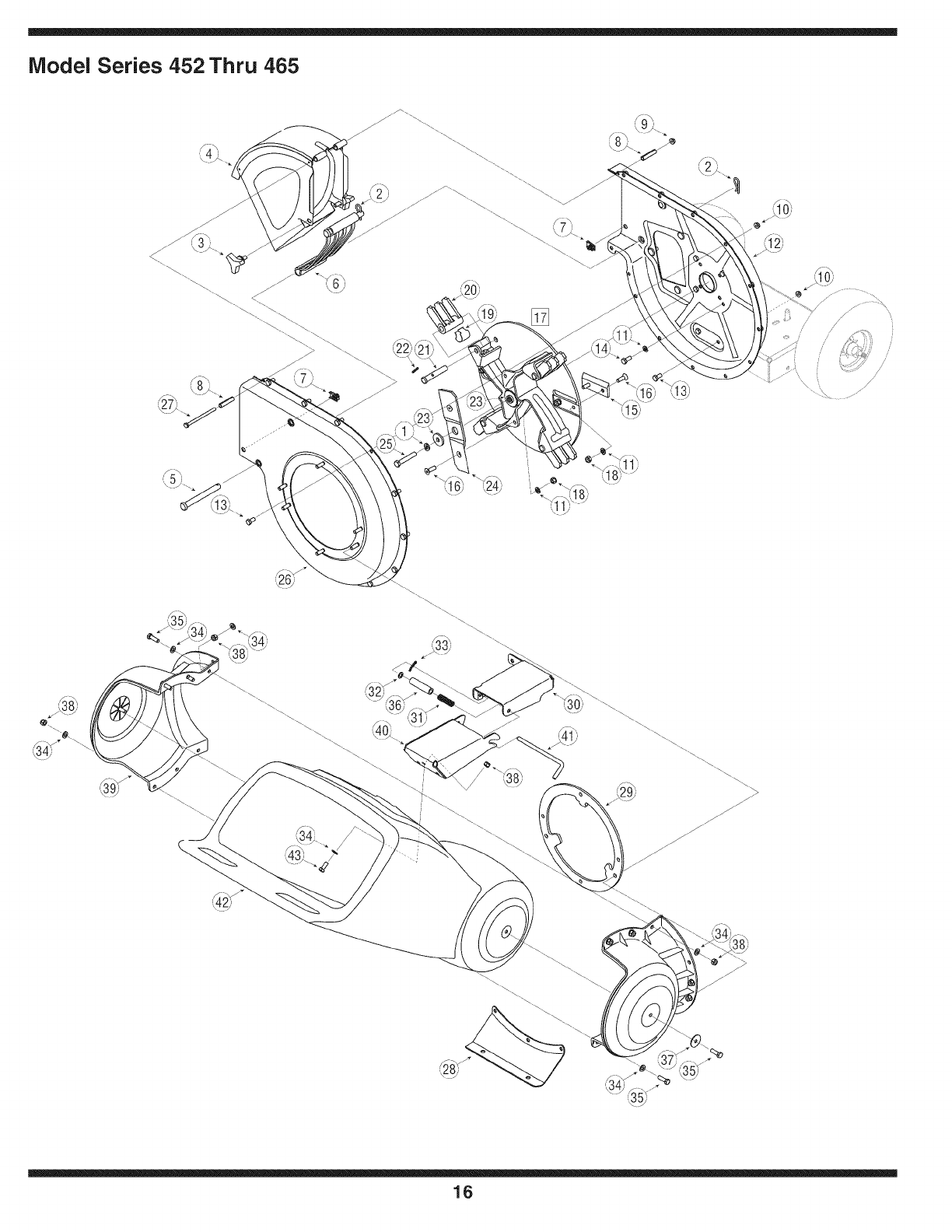
Model Series 452 Thru 465
j_
i •¢/i
16
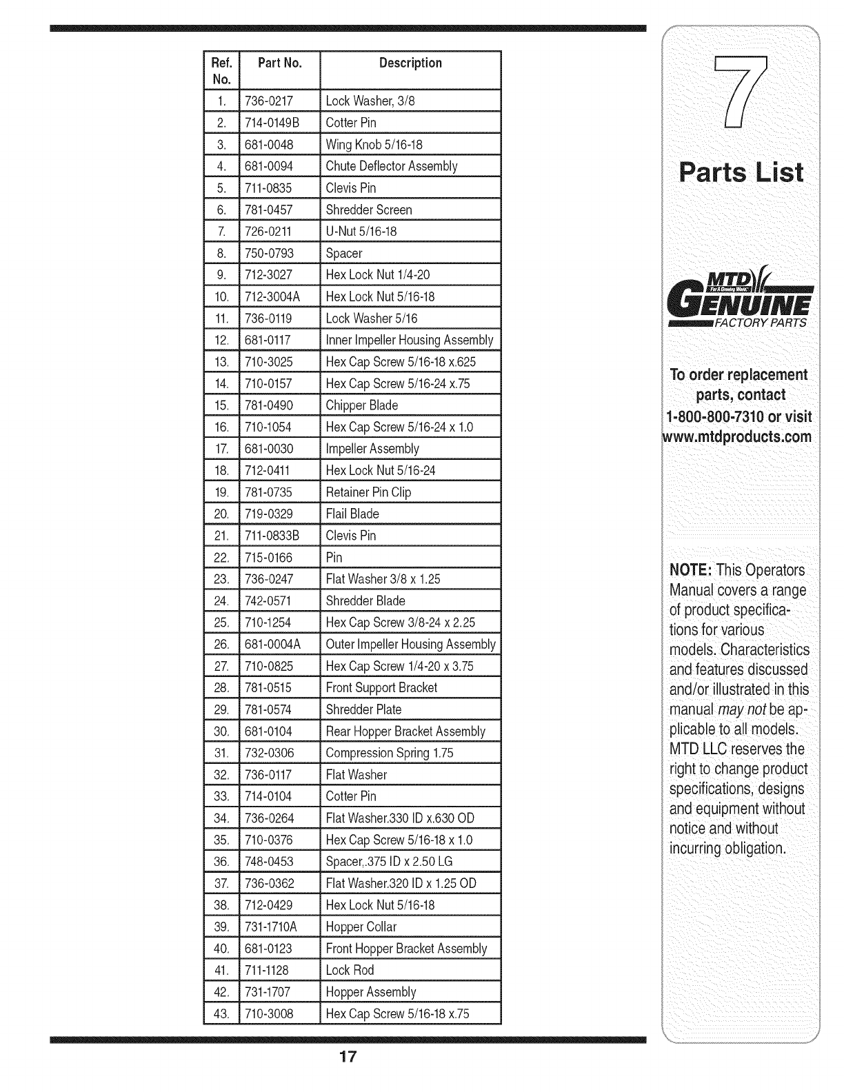
Ref. PartNo. Description
No,
1. 736-0217 LockWasher,3/8
2. 714-0149B CotterPin
3. 681-0048 WingKnob5/16-18
4. 681-0094 ChuteDeflectorAssembly
5. 711-0835 ClevisPin
6. 781-0457 ShredderScreen
7. 726-0211 U-Nut5/16-18
8. 750-0793 Spacer
9. 712-3027 HexLockNut1/4-20
10. 712-3004A HexLockNut5/16-18
11. 736-0119 LockWasher5/16
12. 681-0117 InnerImpellerHousingAssembly
13. 710-3025 HexCapScrew5/16-18x.625
14. 710-0157 HexCapScrew5/16-24x.75
15. 781-0490 ChipperBlade
16. 710-1054 HexCapScrew5/16-24x 1.0
17. 681-0030 impellerAssembly
18. 712-0411 HexLockNut5/16-24
19. 781-0735 RetainerPinClip
20. 719-0329 Flail Blade
21. 711-0833B ClevisPin
22. 715-0166 Pin
23. 736-0247 FlatWasher3/8 x 1.25
24. 742-0571 ShredderBlade
25. 710-1254 HexCapScrew3/8-24 x 2.25
26. 681-0004A OuterlmpellerHousingAssembly
27. 710-0825 HexCapScrew1/4-20x 3.75
28. 781-0515 FrontSupportBracket
29. 781-0574 ShredderPlate
30. 681-0104 RearHopperBracketAssembly
31. 732-0306 CompressionSpring1.75
32. 736-0117 FlatWasher
33. 714-0104 CotterPin
34. 736-0264 FlatWasher.330IDx.630OD
35. 710-0376 HexCapScrew5/16-18x 1.0
36. 748-0453 Spacer,.375IDx2.50 LG
37. 736-0362 FlatWasher.320IDx 1.25OD
38. 712-0429 HexLockNut5/16-18
39. 731-1710A HopperCollar
40. 681-0123 FrontHopperBracketAssembly
41. 711-1128 LockRod
42. 731-1707 HopperAssembly
43. 710-3008 HexCapScrew5/16-18x.75
17
££NUIN£
_FACTORY PARTS
TO order replacement
parts, contact
1.8oo:8oo.7aloor
www:mtaprOaucts;oom
NOTE: This Operators
ManUalcovers a range
of product specifiCa;
tions for Various
models:CharaCteristics
and featuresd iscussed
and/or illustrated inthis
manual may not be ap*
plicable to all model&
MTD LLC reservesthe
right to change product
specifications;designs
and equipmentwithout
noticeand without
incurring obligation
i__ _ii_: !_ iiiiiiiii_!__ii _iii___i_i
i_ _ii_ _ii_ i _ i
i i iiiiiiiiiiii
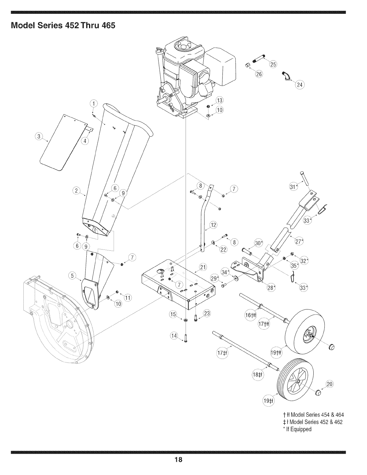
iVlodel Series 452 Thru 465
(16
1ft ModelSeries454 &464
:l:{ ModelSeries452& 462
* If Equipped
18
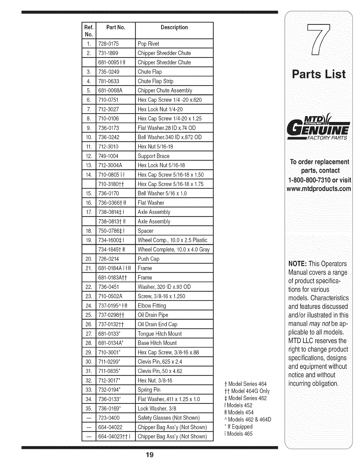
Ref. Part No. Description
No.
1. 728-0175 PopRivet
2. 731-1899 ChipperShredderChute
681-0095{H ChipperShredderChute
3. 735-0249 ChuteFlap
4. 781-0633 ChuteFlapStrip
5. 681-0068A . ChipperChuteAssembly
6. 710-0751 HexCapScrew1/4 -20x.620
7. 712-3027 HexLockNut1/4-20
8. 710-0106 HexCapScrew1/4-20x 1.25
9. 736-0173 FlatWasher.28IDx.74OD
10. 736-0242 BellWasher.340IDx.872OD
11. 712-3010 HexNut5/16-18
12. 749-1004 SupportBrace
13. 712-3004A HexLockNut5/16-18
14. 710-0805_{ HexCapScrew5/16-18x 1.50
710-3180tt HexCapScrew5/16-18x 1.75
15. 736-0170 BellWasher5/16x 1.0
16. 736-0366tH FlatWasher
17. 738-0814_:{ AxieAssembly
738-0813tH Axle Assembly
18. 750-0786_{ Spacer
19. 734-1600_:{ WheelComp.,10.0x 2.5 Plastic
734-1845t{{ WheelComplete,10.0x 4.0 Gray
20. 726-0214 PushCap
21. 681-0184A_{H Frame
681-0183Att Frame
22. 736-0451 Washer,.320IDx.93 OD
23. 710-0502A Screw,3/8-16x 1.250
24. 737-0195A{H ElbowFitting
25. 737-0298tt Oil DrainPipe
26. 737-0132tt Oil DrainEndCap
27. 681-0133" TongueHitchMount
28. 681-0134A* BaseHitch Mount
29. 710-3001" HexCapScrew,3/8-16x.88
30. 711-0299" ClevisPin,.625x2.4
31. 711-0835" ClevisPin,.50x 4.62
32. 712-3017" HexNut,3/8-16
• 33. 732-0194" SpringPin
34. 736-0133" FlatWasher,.411x 1.25x 1.0
35. 736-0169" LockWasher,3/8
-- 723-0400 SafetyGlasses(NotShown)
-- 664-04022 ChipperBagAss'y(Not Shown)
-- 664-04023tt_ ChipperBagAss'y(Not Shown)
t ModelSeries464
tt Model464GOnly
_1ModelSeries462
{ Models452
HModels454
AModels462& 464D
* IfEquipped
Models465
19
=iTS
To order replacement
parts, contact
1-800-800-7310 or visit
www.mtdproducts.com
NOTE: This Operators
Manualcovers a range
of product specifica-
tions for various
models. Characteristics
andfeatures discussed
and/or illustrated inthis
manual may not be ap-
plicableto all models.
MTD LLC reserves the
right to change product
specifications,designs
and equipmentwithout
notice and without
incurring obligation.
MANUFACTURER'S LiMiTED WARRANTY FOR
The limitedwarrantysetforthbelowisgivenby MTDLLCwithrespect
to newmerchandisepurchasedandusedin the UnitedStates,its
possessionsandterritories.
"MTD"warrantsthisproductagainstdefectsinmaterialandworkman-
shipfor a periodof two (2)yearscommencingonthe date of original
purchaseandwill,at itsoption,repairor replace,freeof charge,any
part foundto bedefectiveinmaterialsorworkmanship.Thislimitedwar-
rantyshallonlyapply if thisproducthasbeenoperatedand maintained
inaccordancewiththe Operator'sManualfurnishedwiththe product,
andhas notbeensubjectto misuse,abuse,commercialuse,neglect,
accident,impropermaintenance,alteration,vandalism,theft,fire,water,
ordamagebecauseof otherperilor naturaldisaster.Damageresulting
fromthe installationor useof any part,accessoryor attachmentnot
approvedby MTDfor use withthe product(s)coveredbythis manual
willvoid yourwarrantyas to any resultingdamage.
Normalwearpartsarewarrantedto befree fromdefectsinmaterialand
workmanshipfor a periodof thirty (30)daysfromthe dateof purchase.
Normalwearpartsinclude,butare notlimitedto itemssuchas: batter-
ies,belts,blades,bladeadapters,grassbags,riderdeckwheels,seats,
snowthrowerskidshoes,shaveplates,augerspiralrubberandtires.
HOW TO OBTAIN SERVICE: Warranty service is available,WITH
PROOFOF PURCHASE, through your local authorized service
dealer. To locate the dealer in your area, check your Yellow Pages,
or contact MTD LLC at RO. Box 361131,Cleveland, Ohio 44136-
0019, or call 1-800-800-7310or 1-330-220-4683 or log on to our
Web site at www.mtdproducts.com.
Thislimitedwarrantydoesnot providecoverageinthe followingcases:
a. Theengineor componentpartsthereof.Theseitemsmaycarrya
separatemanufacturer'swarranty.Referto applicablemanufacturer's
warrantyfor termsandconditions.
b. Logsplitterpumps,valves,andcylindershavea separateoneyear
warranty.
c. Routinemaintenanceitemssuchas lubricants,filters,blade
sharpening,tune-ups,brakeadjustments,clutchadjustments,deck
adjustments,andnormaldeteriorationof the exteriorfinishdueto
useor exposure.
d. Servicecompletedby someoneotherthananauthorizedservice
dealer.
e. MTDdoesnot extendanywarrantyfor productssoldor exported
outsideof the UnitedStates,its possessionsandterritories,except
thosesoldthroughMTD'sauthorizedchannelsof exportdistribution.
f. ReplacementpartsthatarenotgenuineMTDparts.
g. Transportationchargesandservicecalls.
No impliedwarranty,includingany impliedwarranty of mer-
chantabilityof fitness for a particular purpose,applies after the
applicable periodof express written warranty above as to the
partsas identified.No otherexpresswarranty, whetherwrittenor
oral, except as mentioned above,givenby any personor entity,
includingadealeror retailer, withrespect to any product,shall
bindMTD.Duringthe periodof the warranty,the exclusiveremedy
is repairor replacementof the productas setforth above.
Theprovisionsas set forth inthis warrantyprovidethe soleand
exclusiveremedy arising from the sale.MTDshallnot be liable
for incidentalor consequentiallossor damage including,without
limitation, expensesincurredfor substituteor replacementlawn
careservicesor for rentalexpensesto temporarily replacea
warranted product.
Somestatesdo notallowthe exclusionor limitationof incidentalor
consequentialdamages,or limitationsonhowlongan impliedwarranty
lasts,sothe aboveexclusionsor limitationsmaynot applyto you.
In noeventshallrecoveryof any kindbegreaterthanthe amountof the
purchasepriceof the productsold.Alterationof safetyfeatures of
the productshallvoid this warranty. Youassumethe riskandliability
for loss,damage,or injuryto you andyourpropertyand/orto othersand
theirpropertyarisingout of the misuseor inabilityto usethe product.
Thislimitedwarrantyshallnot extendto anyoneotherthan theoriginal
purchaserorto the personfor whomitwas purchasedas a gift.
HOWSTATELAWRELATESTOTHIS WARRANTY:This limited
warrantygivesyou specificlegalrights,and youmayalsohaveother
rightswhichvaryfromstateto state.
IMPORTANT:OwnermustpresentOriginalProofof Purchaseto obtain
warrantycoverage.
IViTD LLC, P.O. BOX 361131 CLEVELAND, OHiO 44136-0019; Phone: 1=800=800-7310, 1-330=220-4683
