MTD 430 439 Series 770 10179C User Manual To The 9e092290 Ef53 461b A5ac 3f3e8929f783
User Manual: MTD 430-439 Series to the manual
Open the PDF directly: View PDF ![]() .
.
Page Count: 20
IMPORTANT: Read safety rules and instructions carefully before operating equipment.
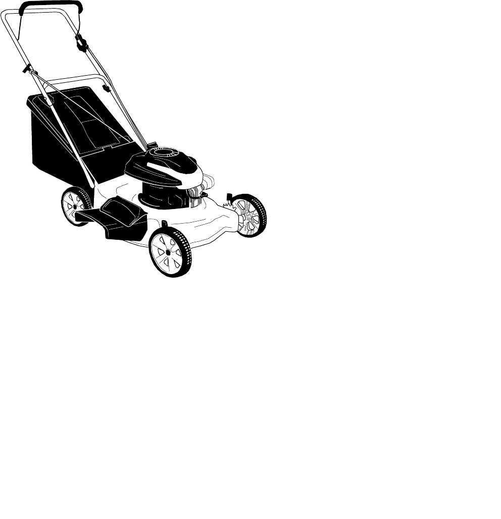
21” Rear & Side
Discharge Mulching
Lawn Mower
Model Series 430-439
PRINTED IN U.S.A.
Warning: This unit is equipped with an internal combustion engine and should not be used on or near any unimproved forest-
covered, brush-covered or grass-covered land unless the engine’s exhaust system is equipped with a spark arrester meeting
applicable local or state laws (if any). If a spark arrester is used, it should be maintained in effective working order by the operator.
In the State of California the above is required by law (Section 4442 of the California Public Resources Code). Other states may have
similar laws. Federal laws apply on federal lands. A spark arrester for the muffler is available through your nearest engine authorized
service dealer or contact the service department, P.O. Box 368022 Cleveland, Ohio 44136-9722.
MTD LLC, P.O. BOX 361131 CLEVELAND, OHIO 44136-0019
Operator’s Manual
FORM NO.
770-10179C.fm
(11/2001)

2
TABLE OF CONTENTS
Content Page
Important Safe Operation Practices................................................................................... 3
Slope Gauge...................................................................................................................... 6
Assembling Your Lawn Mower .......................................................................................... 7
Know Your Lawn Mower.................................................................................................... 10
Operating Your Lawn Mower .............................................................................................11
Maintaining Your Lawn Mower........................................................................................... 12
Service .......................................................................................................................... 13
Making Adjustments .......................................................................................................... 14
Off- Season Storage .......................................................................................................... 15
Troubleshooting.................................................................................................................15
Parts List .......................................................................................................................... 16
FINDING MODEL NUMBER
This Operator’s Manual is an important part of your new Lawn Mower. It will help you assemble, prepare
and maintain the unit for best performance. Please read and understand what it says.
Before you start assembling your new equipment, please locate the model plate on the
equipment and copy the information from it in the space provided below. The information on
the model plate is very important if you need help from our Customer Support Department or
an authorized dealer.
• You can locate the model number by standing behind the unit in the operating position and looking
down at the rear of the deck. A sample model plate is explained below. For future reference, please
copy the model number and the serial number of the equipment in the space below.
ENGINE INFORMATION
The engine manufacturer is responsible for all engine-related issues with regards to performance, power-
rating, specifications, warranty and service. Please refer to the engine manufacturer’s Owner’s/Operator’s
Manual packed separately with your unit for more information.
CALLING CUSTOMER SUPPORT
If you have difficulty assembling this product or have any questions regarding the controls, operation or
maintenance of this unit, please call the Customer Support Department.
Call 1- (800)-800-7310 to reach a Customer Support representative. Please have your unit’s
model number and serial number ready when you call. See previous section to locate this
information. You will be asked to enter the serial number in order to process your call .
www.mtdproducts.com
MTD LLC
P. O. BOX
361131
CLEVELAND,OH
44136
330-220-4683
800-800-7310
Copy the model number here:
Copy the serial number here:
(Model Number) (Serial Number)
For more details about your unit, visit our website at www.mtdproducts.com

3
SECTION 1: IMPORTANT SAFE OPERATION PRACTICES
General Operation
1. Read this operator’s manual carefully in its entirety
before attempting to assemble this machine. Read,
understand, and follow all instructions on the
machine and in the manual(s) before operation. Be
completely familiar with the controls and the proper
use of this machine before operating it. Keep this
manual in a safe place for future and regular
reference and for ordering replacement parts.
2. This machine is a precision piece of power
equipment, not a plaything. Therefore, exercise
extreme caution at all times. Your unit has been
designed to perform one job: to mow grass. Do not
use it for any other purpose.
3. Never allow children under 14 years old to operate
this machine. Children 14 years old and over
should read and understand the operation
instructions and safety rules in this manual and
should be trained and supervised by a parent. Only
responsible individuals who are familiar with these
safe operation rules should use this machine.
4. Thoroughly inspect the area where the equipment
is to be used. Remove all stones, sticks, wire,
bones, toys and other foreign objects which could
be tripped over or picked up and thrown by the
blade. Thrown objects can cause serious personal
injury. Plan your mowing pattern to avoid discharge
of material toward roads, sidewalks, bystanders
and the like. Also, avoid discharging material
against a wall or obstruction which may cause
discharged material to ricochet toward operator.
5. To help avoid blade contact or a thrown object
injury, stay in the operator zone behind the handles
and keep bystanders, helpers, children and pets at
least 75 feet from the machine while it is in
operation. Stop machine if anyone enters the area.
6. Always wear safety glasses or safety goggles
during operation and while performing an
adjustment or repair to protect your eyes. Thrown
objects which ricochet can cause serious injury to
the eyes.
7. Wear sturdy, rough-soled work shoes and close-
fitting slacks and shirts. Shirts and pants that cover
the arms and legs and steel-toed shoes are
recommended. Never operate this machine in bare
feet, sandals, slippery or light weight (e.g. canvas)
shoes.
8. Do not put hands or feet near rotating parts or
under the cutting deck. Contact with the blade can
amputate hands and feet.
9. A missing or damaged discharge cover can cause
blade contact or thrown object injuries.
10. Many injuries occur as a result of the mower being
pulled over the foot during a fall caused by slipping
or tripping. Do not hold on to the mower if you are
falling; release the handle immediately.
11. Never pull the mower back toward you while you
are walking. If you must back the mower away from
a wall or obstruction first look down and behind to
avoid tripping and then follow these steps:
a. Step back from the mower to fully extend
your arms.
b. Be sure you are well balanced with sure
footing.
c. Pull the mower back slowly, no more than
half way toward you.
d. Repeat these steps as needed.
5. Do not operate the mower while under the influence
of alcohol or drugs.
6. Do not engage the self-propelled mechanism on
units so equipped while starting engine.
7. The blade control handle is a safety device. Never
attempt to bypass its operation. Doing so makes
the safety device inoperative and may result in
personal injury through contact with the rotating
blade. The blade control handle must operate
easily in both directions and automatically return to
the disengaged position when released.
WARNING: This symbol points out important safety instructions which, if not followed, could endanger
the personal safety and/or property of yourself and others. Read and follow all instructions in this manual
before attempting to operate this machine. Failure to comply with these instructions may result in personal
injury. When you see this symbol—HEED ITS WARNING
WARNING: This machine was built to be operated according to the rules for safe operation in this
manual. As with any type of power equipment, carelessness or error on the part of the operator can result in
serious injury. This machine is capable of amputating hands and feet and throwing objects. Failure to
observe the following safety instructions could result in serious injury or death.
WARNING: Engine exhaust, some of its constituents, and certain vehicle components contain or
emit chemicals known to State of California to cause cancer and birth defects or other
reproductive harm.
4
8. Never operate the mower in wet grass. Always be
sure of your footing. A slip and fall can cause
serious personal injury. If you feel you are losing
your footing, release the blade control handle
immediately and the blade will stop rotating within
three seconds.
9. Mow in daylight or good artificial light. Walk, never
run. Stop the blade when crossing gravel drives,
walkways or roads.
10. If the equipment should start to vibrate abnormally,
stop the engine and check immediately for the
cause. Vibration is generally a warning of trouble.
11. Shut the engine off and wait until the blade comes
to a complete stop before removing the grass
catcher or unclogging the chute. The cutting blade
continues to rotate for a few seconds after the
engine is shut off. Never place any part of the body
in the blade area until you are sure the blade has
stopped rotating.
12. Never operate mower without proper trail shield,
discharge cover, grass catcher, blade control
handle or other safety protective devices in place
and working. Never operate mower with damaged
safety devices. Failure to do so, can result in
personal injury.
13. Muffler and engine become hot and can cause a
burn. Do not touch.
14. Only use parts and accessories made for this
machine by the original equipment manufacturer
(O.E.M). Failure to do so can cause personal injury.
15. If situations occur which are not covered in this
manual, use care and good judgment. Contact your
dealer for assistance. Telephone 1-800-800-7310
for the name of your nearest dealer.
Slope Operation
Slopes are a major factor related to slip and fall
accidents which can result in severe injury. Operation
on slopes requires extra caution. If you feel uneasy on a
slope, do not mow it. Before operating this unit on a
slope or hilly area, use the slope gauge on page 6 to
measure slopes . If the slope is greater than 15
degrees, do not mow it.
Do:
1. Mow across the face of slopes; never up and down.
Exercise extreme caution when changing direction
on slopes.
2. Watch for holes, ruts, rocks, hidden objects, or
bumps which can cause you to slip or trip. Tall
grass can hide obstacles.
3. Always be sure of your footing. A slip and fall can
cause serious personal injury. If you feel you are
losing your balance, release the blade control
handle immediately, and the blade will stop rotating
within 3 seconds.
Do Not:
1. Do not mow near drop-offs, ditches or
embankments, you could lose your footing or
balance.
2. Do not mow slopes greater than 15 degrees as
shown on the slope gauge.
3. Do not mow on wet grass. Unstable footing could
cause slipping.
Children
Tragic accidents can occur if the operator is not alert to
the presence of children. Children are often attracted to
the mower and the mowing activity. They do not
understand the dangers. Never assume that children
will remain where you last saw them.
1. Keep children out of the mowing area and under
the watchful care of a responsible adult other than
the operator.
2. Be alert and turn mower off if a child enters the
area.
3. Before and while moving backwards, look behind
and down for small children.
4. Use extreme care when approaching blind corners,
doorways, shrubs, trees, or other objects that may
obscure your vision of a child who may run into the
mower.
5. Keep children away from hot or running engines.
They can suffer burns from a hot muffler.
6. Never allow children under 14 years old to operate
a power mower. Children 14 years old and over
should read and understand the operation
instructions and safety rules in this manual and
should be trained and supervised by a parent.
Service
Safe Handling of Gasoline
1. To avoid personal injury or property damage use
extreme care in handling gasoline. Gasoline is
extremely flammable and the vapors are explosive.
Serious personal injury can occur when gasoline is
spilled on yourself or your clothes which can ignite.
2. Wash your skin and change clothes immediately.
3. Use only an approved gasoline container.
4. Never fill containers inside a vehicle or on a truck or
trailer bed with a plastic liner. Always place
containers on the ground away from your vehicle
before filling.
5. If possible, remove gas-powered equipment from
the truck or trailer and refuel it on the ground. If this
is not possible, then refuel such equipment on a
trailer with a portable container, rather than from a
gasoline dispenser nozzle.
6. Keep the nozzle in contact with the rim of the fuel
tank or container opening at all times until fueling is
complete. Do not use a nozzle lock-open device.

5
7. Extinguish all cigarettes, cigars, pipes and other
sources of ignition.
8. Never fuel machine indoors because flammable
vapors will accumulate in the area.
9. Never remove gas cap or add fuel while the engine
is hot or running. Allow engine to cool at least two
minutes before refueling.
10. Never over fill fuel tank. Fill tank to no more than ½
inch below bottom of filler neck to provide space for
fuel expansion.
11. Replace gasoline cap and tighten securely.
12. If gasoline is spilled, wipe it off the engine and
equipment. Move unit to another area. Wait 5
minutes before starting the engine.
13. Never store the machine or fuel container inside
where there is an open flame, spark or pilot light as
on a water heater, space heater, furnace, clothes
dryer or other gas appliances.
14. To reduce fire hazard, keep mower free of grass,
leaves, or other debris build-up. Clean up oil or fuel
spillage and remove any fuel soaked debris.
15. Allow a mower to cool at least 5 minutes before
storing.
General Service
1. Never run an engine indoors or in a poorly
ventilated area. Engine exhaust contains carbon
monoxide, an odorless and deadly gas.
2. Before cleaning, repairing, or inspecting, make
certain the blade and all moving parts have
stopped. Disconnect the spark plug wire and
ground against the engine to prevent unintended
starting.
3. Check the blade and engine mounting bolts at
frequent intervals for proper tightness. Also,
visually inspect blade for damage (e.g., bent,
cracked, worn) Replace blade with the original
equipment manufacture’s (O.E.M.) blade only,
listed in this manual. “Use of parts which do not
meet the original equipment specifications may
lead to improper performance and compromise
safety!”
4. Mower blades are sharp and can cut. Wrap the
blade or wear gloves, and use extra caution when
servicing them.
5. Keep all nuts, bolts, and screws tight to be sure the
equipment is in safe working condition.
6. Never tamper with safety devices. Check their
proper operation regularly.
7. After striking a foreign object, stop the engine,
disconnect the spark plug wire and ground against
the engine. Thoroughly inspect the mower for any
damage. Repair the damage before starting and
operating the mower.
8. Never attempt to make a wheel or cutting height
adjustment while the engine is running.
9. Grass catcher components, discharge cover, and
trail shield are subject to wear and damage which
could expose moving parts or allow objects to be
thrown. For safety protection, frequently check
components and replace immediately with original
equipment manufacturer’s (O.E.M.) parts only,
listed in this manual. “Use of parts which do not
meet the original equipment specifications may
lead to improper performance and compromise
safety!”
10. Do not change the engine governor setting or
overspeed the engine. The governor controls the
maximum safe operating speed of the engine.
11. Maintain or replace safety and instruction labels, as
necessary.
12. Observe proper disposal laws and regulations.
Improper disposal of fluids and materials can harm
the environment.
Your Responsibility
•Restrict the use of this power machine to persons
who read, understand and follow the warnings and
instructions in this manual and on the machine.
1299 AC
6
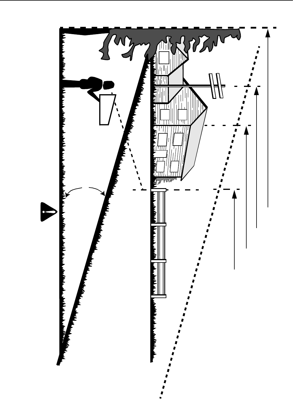
SECTION 2: SLOPE GAUGE
15°
SIGHT AND HOLD THIS LEVEL WITH A VERTICAL TREE
A POWER POLE
A CORNER OF A BUILDING
OR A FENCE POST
FOLD ON DOTTED LINE, REPRESENTING A 15° SLOPE
USE THIS PAGE AS A GUIDE TO DETERMINE SLOPES WHERE YOU MAY NOT OPERATE SAFELY.
Do not mow on inclines with a slope in excess of 15 degrees (a rise of approximately 2-1/2 feet every 10 feet). A riding mower could overturn
and cause serious injury. If operating a walk-behind mower on such a slope, it is extremely difficult to maintain your footing and you could slip,
resulting in serious injury.
Operate RIDING mowers up and down slopes, never across the face of slopes.
Operate WALK-BEHIND mowers across the face of slopes, never up and down slopes.
WARNING
7
SECTION 3: ASSEMBLING YOUR LAWN MOWER
Removing Unit From Carton
•Remove staples, break glue on top flaps or cut tape
at carton end and peel top flap to open carton.
•Remove loose parts if included with unit.
•Cut corners and lay carton down flat. Remove
packing material.
•Roll or slide unit out of carton. Check carton
thoroughly for loose parts.
NOTE: Make sure not to crimp cables while removing
the loose parts or the entire unit from the carton.
Tools Required
•Pair of Pliers
•Funnel
•Set of adjustable wrenches
NOTE: This manual covers several models of lawn
mowers. Folow the information pertaining to your
mower only. Reference to right or left hand side of the
mower is observed from the operating position.
Disconnecting Spark Plug
•Before setting up your lawn mower, disconnect the
spark plug wire from the spark plug, and ground it to
a bolt, retaining post or V-slot on the engine. See
Figure 1.
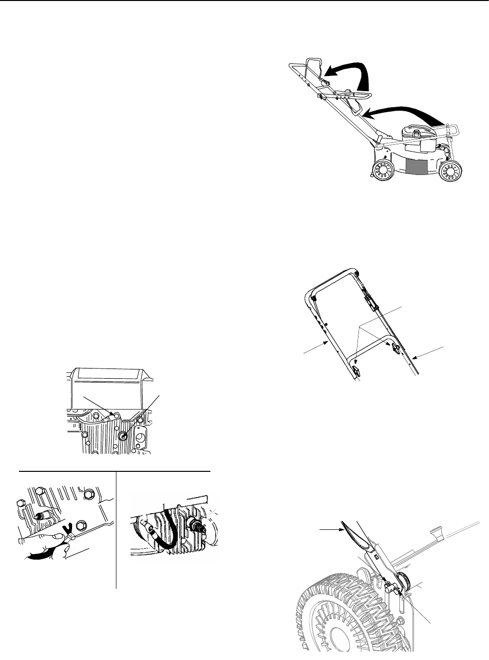
Figure 1
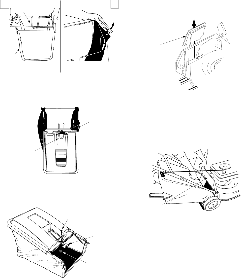
Assembling Handle
•For shipping purposes, the grass bag was placed
on top of the unit. Remove it from the unit and set it
out of the way. See Figure 2 .
Figure 2
•Raise the lower handle, as shown in Figure 2 , till it
snaps into place.
•Raise the upper handle as shown in Figure 2 .
•Tighten the two wing nuts which are already on the
handle. See Figure 3 .
Figure 3
NOTE: Make sure to route the cables outside the lower
handle. Also do not crimp the cables while lifting the
handle up.
•For shipping purposes, the hairpin clip is placed in
the outer hole of the weld pin on the lower handle.
Remove the hairpin clip from the outer hole of the
weld pin.
•Using a pair of pliers, insert the hairpin clip into the
inner hole in the weld pin. Repeat on the other side.
See Figure 4 .
Figure 4
Spark Plug Wire Spark Plug
All Engines with Rubber Boot
Briggs & Stratton Engines Tecumseh Engines
Tighten these
wing nuts
Lower
Handle
Upper
Handle
Inner Hole
Hairpin Clip
Lower Handle
8
•Insert post of cable ties that are on lower handle
into the holes provided on the lower handle. The
holes may be on the inside or outside. Pull cable
ties tight and cut off the extra. See Figure 5 below.
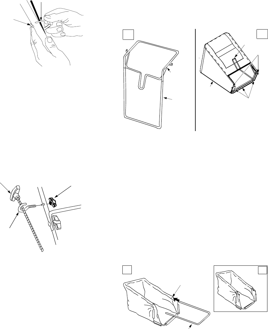
Figure 5
Attaching Starter Rope
The rope guide is already attached to the right side of
the lower handle of your mower. See Figure 6 .
•With the spark plug wire disconnected and
grounded, hold the blade control handle against the
upper handle, and pull the starter rope up to the
rope guide. See Figure 6.
•Slip the rope through the rope guide as shown
below. Tighten the wing nut holding the rope guide
to the lower handle.
Figure 6
Grass Catcher Assembly
NOTE: Make certain the grass bag is turned right side
out before assembling (warning label will be on the
outside).
Parts for Soft Grass Bag
1. Front Frame
2. Rear Frame
3. Bag
Assembling Soft Grass Bag
•Join the rear frame and front frame assembly as
shown in Figure 7 A.
•Place the bag over the frame (black plastic side is
the bottom of bag). Slip the openings in the side of
the plastic channels on the bag over the hooks on
the grass catcher frame.
•Secure bag to frame by working the plastic
channels on bag over frame as shown in Figure 7 B.
All of the plastic channels except the center top of
the bag attach from the outside of bag. The center
top of the bag attaches from inside the bag.
Figure 7
Parts for Hardtop Grass Bag
1. Rear Frame (packed inside hardtop cover)
2. Front Frame
3. Bag
4. Hardtop Cover
5. Mounting Bracket
6. Hex Lock Nut
7. Phillips Screw
Assembling Hardtop Grass Bag
•Insert one end of the rear frame into the slit in the
cloth channel on the edge of the grass bag (slits are
approximately 6 inches from the end of the bag).
See Figure 8A. Feed all the bag material on one
side of the frame before working it around frame.
Make certain the other end of rear frame comes out
the slit in the other side. See Figure 8B.
Figure 8
•Slide the ends of the front frame assembly into the
ends of the rear frame as shown in Figure 9 A. The
handle of the front frame assembly should be away
Cable Tie
Post on
Cable Tie
Slip rope into
rope guide
Wing Nut
Rope
Guide
Front
Frame
Assembly
Rear
Frame
Bag
Hook
Plastic
Channels
AB
Frame
Note: Bag-Fill Indicator, shown
here, is an optional item
Rear Frame
Slit
A
B
9
from the black plastic bottom of the bag. Push the
two frames together until the cross piece on the
front frame contacts the rear frame.
•Slip the openings in the side of the plastic channel
on the bag over hooks on the grass catcher frame.
See Figure 9 B.
•Secure front of bag to front frame by working the
five plastic channels on bottom, sides and top of
bag over frame.
Figure 9
•Hold the bag and frame so the bag hangs from the
frame (is not bunched around the frame). Slide the
handle on the grass catcher frame down into the
slot in the hardtop cover as shown in Figure 10.
Figure 10
•Press the rear frame into the two tabs at the back of
the hardtop cover and the cross bar on the front
frame into the channel on the front of the hardtop
cover. Some force may be required.
Figure 11
•Place the mounting bracket under the front of the
handle, with the tabs on the bracket facing up.
Insert phillips head screws down through the
hardtop cover and mounting bracket. Secure with
hex lock nuts. See Figure 11.
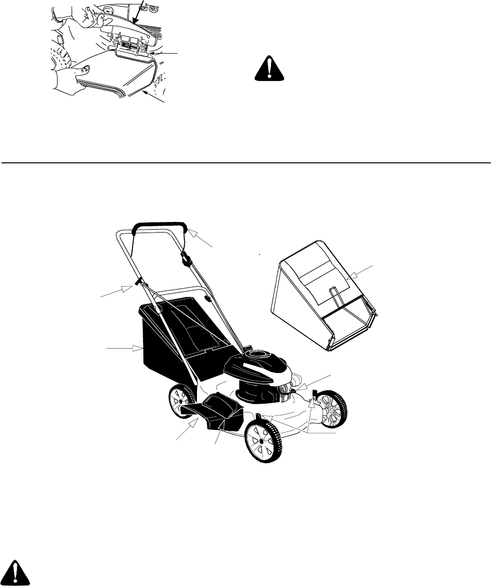
Attaching Grass Catcher
•If your mower is equipped with a mulching plug,
and it is in place on the mower, lift the rear
discharge door and remove the rear mulching plug
from the mower. See Figure 12 .
Figure 12
NOTE: Make sure that the cables are routed to the
outside of the handle when attaching the grass catcher.
•Lift the rear discharge door.
•Place the hooks of the grass catcher into the slots
in the handle bracket assemblies on both sides.
See Figure 13 . Release the rear discharge door.
Figure 13
Removing Grass Catcher
•Lift the rear discharge door on the mower.
•Lift the grass catcher up, out of the slots in the
handle bracket assemblies.
•Reinstall the plastic rear mulching baffle.
•Release the rear discharge door.
Black
Plastic
Bottom
Handle
Hook
B
A
Slot In
Hardtop
Cover
Grass
Catcher
Handle
Phillips
Head
Screw
Mounting
Bracket
Hex Lock
Nut
Rear
Mulching
Plug
Rear Discharge Door
10
Converting to Side-Discharge
Figure 14
•Your mower has been shipped as a mulcher. To
convert it to a side-discharge mower, lift the
mulching plug. Slide the two hooks on the side-
discharge deflector under the hinge pin on the
mulching plug assembly. Lower the mulching plug.
See Figure 14 .
•Do not remove the side mulching plug at any time,
even when you are not mulching.
SECTION 4: KNOW YOUR LAWN MOWER
Read this owner’s manual and safety rules before operating your lawn mower. Compare the illustrations in Figure
15 with your lawn mower to familiarize yourself with the location of various controls and adjustments.
Figure 15
Blade Control Handle
The blade control handle is located on the upper handle
of the mower. The blade control handle must be
depressed in order to operate the unit. Release the
blade control handle to stop the engine and the blade.
Cutting Height Adjustment Lever
This lever, located at each wheel, lets you adjust
cutting height of the grass. Remember to put all four
levers at the same height to avoid uneven cut.
Throttle Control
The engine is equipped with a constant speed throttle
for maximum engine and cutting performance.
Recoil Starter
The recoil starter is attached to the handle. Stand
behind the unit and pull the recoil starter to start engine.
Side
Chute
Deflector
Mulching
Plug
Hinge
Pin
WARNING: Never operate the mower
unless the hooks on the grass catcher are
seated in the slots on the handle bracket
assemblies, and the rear discharge door rests
firmly against the top of the grass catcher.
Blade Control
Grass Catcher
Grass Bag-Fill
Indicator (Optional)
Height Adjustment
Recoil Starter
Handle
Side-Discharge
Spark Plug
Lever
Chute Mulch Plug
WARNING: The blade control handle is a
safety device. Never attempt to bypass its
operations. The blade will be rotating whenever
the engine is running.

11
Primer
The primer is used to pump gas into the carburetor. Use
it to assist in starting a cold engine, but do not use it
when restarting a warm engine after a short shutdown.
Mulching Plug
Both the mulching baffle and the mulching plug are
used only for mulching purposes. Instead of collecting
the grass clippings in a grass catcher, some mower
models have the option of recirculating the clippings
back to the lawn. This is called mulching.
Grass Bag Fill Indicator (If equipped)
In some models, the grass bag is equipped with a bag-
fill indicator to add convenience to your work. While the
mower is running, air will flow through the bag and into
the “sail.” If the grass catcher is empty, air flows
through easily pushing the sail up. If the grass catcher
is full, air does not flow through it allowing the sail to
fall. So the position of the sail acts as a bag-fill indicator
signifying when to empty the grass bag.
SECTION 5: OPERATING YOUR LAWN MOWER
Gas and Oil Fill-Up
•Service the engine with gasoline and oil as
instructed in the separate engine manual packed
with your mower. Read instructions carefully.
Before Starting Mower
•Attach spark plug wire to spark plug. Make certain
the metal cap on the end of the spark plug wire
(inside the rubber boot) is fastened securely over
the metal tip on the spark plug.
Starting Engine
•Push the primer three times. Wait two seconds
between each push. In temperatures below 55° F,
prime five times. Do not prime to restart a warm
engine after a short shutdown.
•Standing behind the mower, depress the blade
control handle and hold it against the upper handle.
•Grasp starter handle and pull rope out slowly until
engine reaches start of compression cycle (rope
will pull slightly harder at this point). Let the rope
rewind slowly. Pull rope with a rapid, continuous,
full arm stroke. Keeping a firm grip on the starter
handle, let the rope rewind slowly.
Stopping Engine
•Release blade control handle to stop the engine
and the blade.
•Disconnect spark plug wire and move away from
spark plug to prevent accidental starting.
Operating Your Lawn Mower
•Once the engine has started, squeeze the blade
control handle against the upper handle to run the
lawn mower.
•Do not operate the mower without the mulching
cover, the grass catcher bag, or the discharge
chute properly installed.
•Be sure that the lawn is clear of stones, sticks, wire,
or other objects which could damage lawn mower
or engine. Such objects could be accidently thrown
by the mower in any direction and cause serious
personal injury to the operator and others.
•For best results, do not cut wet grass because it
tends to stick to the underside of the mower,
preventing proper discharge of grass clippings,
poor mulching conditions, and could cause you to
slip and fall. New grass, thick grass, or wet grass
may require a narrower cut.
•For a healthy lawn, always cut off one-third or less
of the total length of the grass. Lawn should be
trimmed in fall as long as there is growth.
WARNING: Never fill fuel tank indoors, or
when engine is running or hot. Do not smoke
when filling up the fuel tank.
WARNING: Be sure no one other than the
operator is standing near the lawn mower while
starting engine or operating mower.
WARNING: Never run engine indoors or in
enclosed, poorly ventilated areas. Engine
exhaust contains carbon monoxide, an
odorless and deadly gas.
WARNING: Keep hands, feet, hair and
loose clothing away from any moving parts on
engine and lawn mower.
WARNING: If you strike a foreign object,
stop the engine. Remove spark plug wire from
spark plug, thoroughly inspect the mower for
any damage. Repair the damage before
restarting and operating the mower. Extensive
vibration of the mower during operation is an
indication of damage.

12
Bagging Grass Clippings
You can use the grass catcher bag to collect clippings
while you are operating the mower.
•Attach the grass catcher following instructions on
page 9 of this manual. Grass clippings will
automatically collect in the bag as you run mower.
•Operate mower till the grass bag is full. Refer to
page 11 for description of flow indicator, if so
equipped.
•Stop the engine completely by releasing the control
handle. Make sure that the unit has come to a
complete stop.
•Lift discharge door and pull grass bag up and away
from the mower to dispose of the grass clippings.
Using the Mulcher
•For effective mulching, do not cut wet grass
because it tends to stick to the underside of the
deck, preventing proper mulching of grass
clippings. New or thick grass may require a
narrower cut. The ground speed should be
adjusted to the condition of the lawn. If mowing has
been delayed and the grass has been allowed to
grow in excess of 4", mulching is not
recommended. Mow using the grass bag (if so
equipped) to reduce the grass height to 3-1/4"
maximum before mulching.
Adjusting Cutting Height
Refer to height adjustments section of this manual on
page 14 for instruction on how to adjust the cutting
height and the handle height.
•For best results in mowing, keep the cutting height
position high until you have determined which
cutting height is preferred.
SECTION 6: MAINTAINING YOUR LAWN MOWER
Cleaning the Lawn Mower
•Clean underside of the mower deck after each use
to prevent any build-up of grass. If this debris
accumulates, it will cause rust and corrosion.
NOTE: We do not recommend the use of pressure
washers or garden hose to clean your unit. These may
cause damage to electric components, spindles,
pulleys, bearings or the engine. The use of water will
result in shortened life and reduced serviceability.
•Disconnect spark plug wire. Drain gasoline from the
mower, or place a piece of plastic under gas cap.
•Tilt the mower so that the side with the air cleaner is
facing up. Hold the mower firmly.
•Scrape and clean the underside of the deck with a
suitable tool. Do not spray with water.
•Put mower back on its wheels and remove plastic.
Engine Maintenance
A list of key maintenance jobs required for good
performance by the mower is given below. Follow the
engine manual for detailed list and instructions.
•Change engine oil as specified in the engine
manual. Check oil level before starting engine
every time.
•Service foam filter in the air cleaner as specified in
the engine manual. Service air filter more frequently
in extremely dusty conditions.
•Clean engine periodically. Remove dirt and debris
with a cloth or brush.
•Clean spark plug and reset the gap to.030” at least
once a season or every 50 hours of operation.
•Inspect muffler periodically, and replace if
necessary. Damaged mufflers or spark arresters
can create a fire hazard.
IMPORTANT:
Make sure to avoid muffler and
surrounding areas while the mower engine is hot
because temperature of these areas of the engine may
exceed 150o F.
Lubrication
(See Figure 16 )
Wheels
•Lubricate the wheels and bearings, if so equipped,
at least once a season with light oil or engine oil.
Also, if the wheels are removed for any reason,
lubricate the surface of the axle bolt and the inner
surface of the wheel with light oil.
Chute Deflector & Rear Discharge Door
•Lubricate the torsion spring and the pivot point on
each end of the rear discharge door using a light oil.
This will prevent rusting.
WARNING: Always stop engine and
disconnect spark plug wire before performing
any maintenance or adjustments on the mower.
WARNING: Never tip mower more than 90
degrees in any direction and do not leave it
tipped for long. Oil can drain into the upper part
of the engine causing a starting problem.
13
Engine
•Follow the engine manual instructions and
recommended schedule for lubricating engine.
Pivot Points
•Lubricate the pivot points on the discharge chute
door, blade control handle and the cutting height
adjustment lever at least once a season with light
oil. The blade control handle must operate freely in
both directions. The cutting height adjustment
levers should be able to move easily.
Figure 16
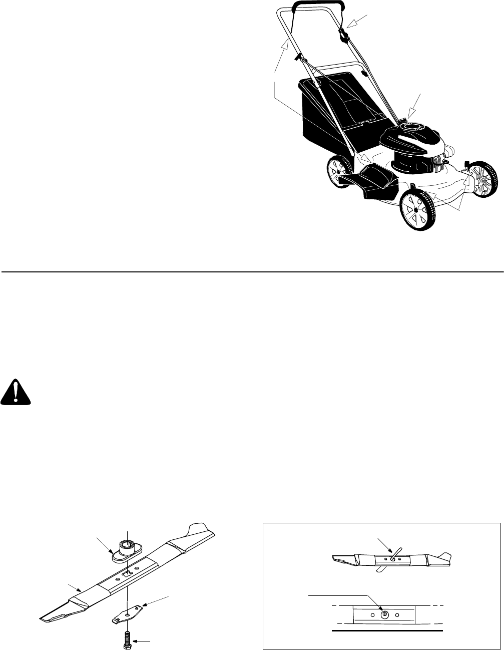
SECTION 7: SERVICING YOUR MOWER
Blade Care
Periodically inspect the blade adapter and pulley for
cracks, especially if you strike a foreign object. Replace
when necessary.
•Disconnect spark plug wire from spark plug.
•Turn mower on its side making sure that the air filter
and the carburetor are up.
•Remove the bolt and blade support or bell washer
which hold the blade and adapter to the engine
crankshaft. See Figure 17. Remove the blade and
adapter from the crankshaft.
Figure 17
To Sharpen Blade:
•The blade can be sharpened with a file or on a
grinding wheel. Do not attempt to sharpen the
blade while it is still on the mower.
•Follow the original angle of grind as a guide. Make
sure that each cutting edge receives an equal
amount of grinding to prevent an unbalanced blade.
NOTE: An unbalanced blade will cause excessive
vibration when rotating at high speeds, may cause
damage to the mower and could break causing
personal injury.
•The blade can be tested by balancing it on a round
shaft screwdriver. See Figure 18. Remove metal
from the heavy side until it balances evenly. It is
recommended that the blade always be removed
from the adapter for the best test of balance.
Figure 18
Lubricate
Lubricate
Lubricate
Follow engine manual
for lubrication
WARNING: When removing the cutting
blade for sharpening or replacement, protect
hands by using heavy gloves or a thick rag to
grasp the cutting blade.
Blade Adapter
Blade
Blade
Bell
Support
Hex Bolt
1. Insert screw driver through hole
2. Blade should be parallel to ground
Screw
Driver
Ground
Blade
14
•Before reassembling the blade and the blade
adapter to the unit, lubricate the engine crankshaft
and the inner surface of the blade adapter with light
oil (or engine oil). Also lubricate the bolt holes, bolts
and inner surface of the nuts.
•Install the blade adapter on the crankshaft with the
“star” away from the engine. Refer to Figure 17.
Place the blade with the side marked bottom (or
with part number) facing away from the adapter.
•Align the blade bell support over the blade with the
tabs in the holes of the blade and insert the hex
bolt. Tighten the hex bolt to the torque listed in the
“Blade Mounting Torque” section below.
Blade Mounting Torque
Center Bolt: 450 in. lbs. min., 600 in. lbs. max.
IMPORTANT:
To ensure safe operation, all nuts and
bolts must be checked periodically for correct tightness.
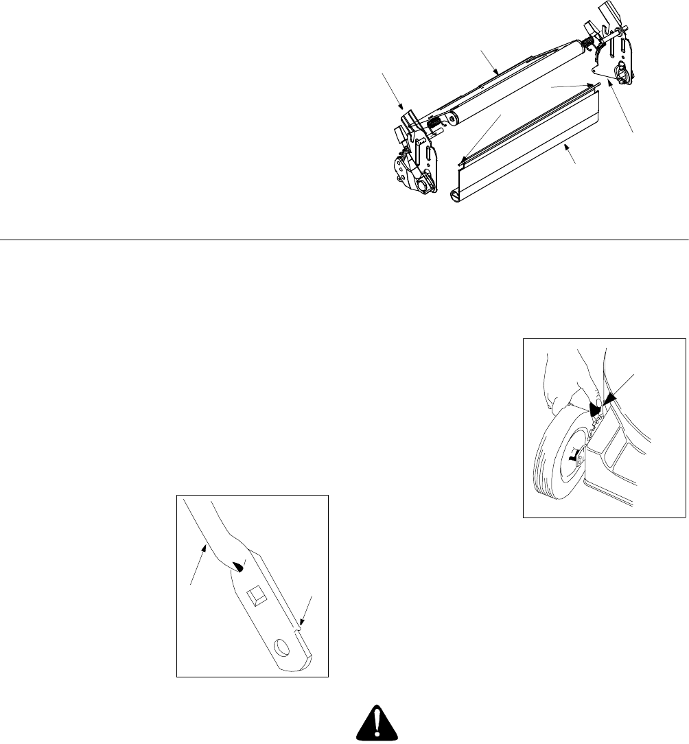
Replacing Rear Flap
•To remove rear flap, cut off the flat end of the wire
rod which secures it to the deck. See Figure 19 .
•Attach the new flap and new rod to deck, bending
the ends of the new rod over to secure to deck.
Figure 19
SECTION 8: MAKING ADJUSTMENTS
Adjusting Handle Height
Your mower is shipped with the handle in the higher
height position. To lower height, proceed as follows.
•Remove the starter rope from the rope guide.
•Remove the upper handle by removing the hand
knobs and carriage bolts. Lay upper handle out of
the way, being careful not to bend or kink cables.
•Remove the hairpin clips from the weld pins on the
handle brackets. Refer to Figure 4. Press out on the
legs of the lower handle. Remove lower handle
from the mower.
•Turn the lower handle
around so the notch on
the bottom of the lower
handle is facing forward
as shown in the box
here. Reassemble,
placing the bottom
holes in the handle over
the weld pins in the
handle mounting
bracket.
•Reassemble the upper
handle to the lower handle.
•Insert hairpin clips in the inner holes of the weld
pins and attach the starter rope as instructed in the
“Assembling Your Lawn Mower” section.
Adjusting Cutting Height
IMPORTANT:
All wheels must be placed in the same
relative position. For rough or uneven lawns, move the
height adjustment lever to a higher position. This will
help stop scalping of the grass.
An adjusting plate and
thumb lever at each wheel
position provides cutting
height adjustment. Each
adjusting plate has nine
height positions. Height of
cut will change when you
move the thumb lever
from one position to
another.
•Simply depress the
lever towards the
wheel and move the lever assembly to desired
position. See the illustration in the box above.
Adjusting Carburetor
NOTE: A dirty air cleaner may cause an engine to run
rough too. Make sure that the air cleaner is clean and
attached to the carburetor before deciding to adjust the
carburetor.
To adjust carburetor, please follow the engine manual.
Handle
Bracket
Handle
Bracket
Rear Discharge
Door
Wire Rod
Rear Flap
Lower
Handle
Notch
WARNING: If any adjustments are made to
the engine (e.g. carburetor) while the engine is
running, keep clear of all moving parts. Be
careful of heated surfaces like the muffler.
Adjustment
Lever

15
SECTION 9: OFF-SEASON STORAGE
Prepare your lawn mower for storage at the end of the
season or if the unit will not be used for 30 days or
more. Store the mower in a clean, dry area.
Gasoline
•Do not store gasoline from one season to another.
Gasoline, stored more than one month, may affect
engine performance.
•Replace your gasoline can if it starts to rust. Rust
and/or dirt in the gasoline will cause problems.
Engine
•Follow recommendations in the accompanying
engine manual for off-season storage of the
engine.
Mower
NOTE: If storing the mower in an unventilated or metal
storage shed, make sure to rustproof the equipment
with a light oil or silicone.
•Store unit in a clean, dry area. Do not store next to
corrosive materials, such as fertilizer or rocksalt.
•Clean underside of the mower according to
instructions on page 12 .
NOTE: We do not recommend the use of pressure
washers or garden hose to clean your unit. They may
cause damage to electric components, spindles,
pulleys, bearings or the engine. The use of water will
result in shortened life and reduce serviceability.
•Lubricate the mower as instructed on page 12.
•You can fold your mower’s handle for convenience
of storage .
•Inspect and replace/sharpen blade, if required.
Refer to page 13.
SECTION 10: TROUBLE-SHOOTING GUIDE
NOTE: For repairs beyond the minor adjustments listed above, contact your nearest authorized service dealer.
Problem Possible Cause Corrective Action
Engine fails to start 1. Blade control handle disengaged
2. Spark plug wire disconnected
3. Fuel tank empty, or stale fuel
4. Blocked fuel line
5. Faulty spark plug
6. Engine flooded
1. Engage blade control handle
2. Connect wire to spark plug
3. Fill up tank with fresh gasoline
4. Clean fuel line
5. Clean, adjust gap, or replace
6. Wait a few minutes and start again.
Engine runs erratic 1. Spark plug wire loose
2. Blocked fuel line or stale fuel
3. Vent in gas cap plugged
4. Water or dirt in fuel system
5. Dirty air cleaner
1. Connect and tighten spark plug wire.
2. Clean fuel line, fill tank with clean, fresh
gasoline.
3. Clear vent.
4. Drain fuel tank. Refill with fresh fuel.
5. Clean air cleaner. Refer to engine manual.
Engine overheats 1. Engine oil level low
2. Air flow restricted
1. Fill crankcase with proper oil.
2. Clean lawn mower engine.
Occasional skip at high
speed
1. Spark plug gap too close 1. Adjust gap to.030 inches.
Idles poorly 1. Spark plug fouled, faulty, or gap too wide
2. Dirty air cleaner
1. Reset gap or replace spark plug.
2. Clean air cleaner.
Excessive vibration 1. Cutting blade loose or unbalanced
2. Bent cutting blade
3. Bent engine crankshaft
1. Tighten blade and adapter, balance blade.
2. Replace blade.
3. Contact your nearest service center
Fails to mulch grass 1. Wet grass
2. Excessively high grass
3. Dull blade
1. Wait until grass is dry to cut.
2. Mow once at a high cutting height, then
mow again at desired height.
3. Sharpen or replace blade.
Uneven cut 1. Wheels not in same height position
2. Dull blade
1. Reposition all wheels at same height.
2. Sharpen or replace blade.
16
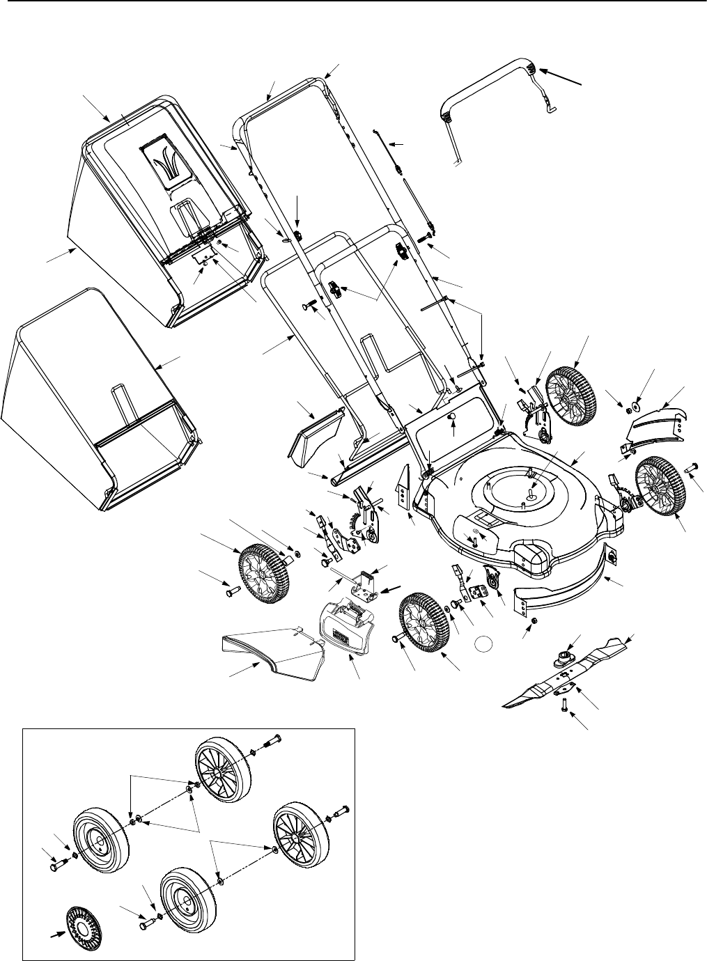
SECTION 11: PARTS LIST FOR MODEL SERIES 430-439
1
11 16
61
15
70
18
69
3
2
68
19
19
4
6
4
31
50
48
47
44
45
79
56
20
55
63
36
34
33
32
40
57
59
59
20
46
46
4544
43
41
42
59
59
23
66
67
58
30
51
53
62
65
81
49
22
72
21
14
13
12
71
52
54
39
40
76
79 45
80
46
76
Hardware for wheel 734-1978
80
64
29
28
35
77

17
Ref.
No Part No. Description
1 747-1161A Control Handle
2 710-1205 Rope Guide
3 720-0279 Handle Knob 1/4-20 Thd.
4 710-1174 Curved Hd. Bolt 5/16-18 x 2"
5 731-2626 Bail Cover †
6 720-0284 Hand Knob
11 749-1092A Upper Handle
12 720-0295 Foam Grip †
13 749-0928 Lower Handle
14 726-0240 Cable Tie
15 764-0310 Rear Catcher Frame
16 746-1130 Control Cable - 40”
746-0554 Control Cable - 40.5”
746-0551 Control Cable - 43”
746-1137 Control Cable - 53”
18 764-0311 Front Catcher Frame
19 764-0309 Grass Bag (for hard top)†
764-0457A Grass Bag (soft top w/logo)
664-0176 Grass Bag (Half Sail)
664-0175 Grass Bag (Full Sail)
20 714-0104 Int. Cotter Pin 5/16" Dia.
21 732-0678 Door Spring - R.H.
22 732-0677 Door Spring - L.H.
23 782-7000 Rear Discharge Door
28 732-0731 Torsion Spring
29 747-0710 Hinge Pin
30 732-0700 Wire Rod
31 731-1236 Rear Flap
32 753-0588 Blade Adapter (Kit includes 32-34)
33 710-1044 Hex Bolt 3/8-24 x 1.5" Lg.
34 736-0524A Blade Bell Support
35 782-7006 Mounting Bracket
36 742-0741 21" Mulching Blade
40 712-0431 Flange Nut 3/8-16 Thd.*
41 15261A Height Adj. Plate
42 15262B Pivot Bar
43 14832 Front Spring Lever Ass’y. w/Knob
44 738-0507B Shld. Bolt .5" Dia. x .357"
45 736-0105 Bell Washer .38" I.D. x .88" O.D.
46 738-0102 Front Axle Bolt
47 720-0426 Spring Lever Knob
48 732-0404 Rear Spring Lever
49 14578 Height Adj. Assy. Comp. - RH
14579 Height Adj. Assy. Comp. - LH ‡
50 14765 Pivot Bar R.H.
N/I 14766 Pivot Bar L.H.
51 782-5002 Front Baffle
52 710-0654A Hex L-Wash.Scr. 3/8-16 x 1"
53 782-5003 Rear Baffle
54 710-1017 Torx Mach AB-Tap Scr. 1/4 x.62"
55 710-0896 HexIndWash. Scr. 1/4-14:.625
56 682-0516A Handle Brkt. Ass’y.—RH
57 682-0515A Handle Brkt. Ass’y.—LH
58 782-0047A Cutting Deck
59 734-1987 Wheel w/ Bearings Grey Link Thd.
734-1988 Wheel w/ Bearings Grey Bar Thd.
734-1978 Wheel w/ Bearings Black Link Thd.
61 731-1876 Hard Top Cover w/ Icon
731-1322A Hard Top Cover w/o Icon
62 736-0270 Bell Washer 1/4" I.D.
63 682-7000 Hinged Mulching Plug
64 731-1409 Chute Deflector: Side Discharge
65 710-0599 Hex Hd Self-Tp Scr. 1/4-20 x .5"
66 782-5007A Mulching Baffle Plug
67 782-5004 Mulching Baffle - R.R.
68 710-0286 Pan Hd. Mach. Scr. 1/4-20:.5” Lg.
69 712-0324 Hx. Nylon L-Nut - 1/4-20 Thread
70 782-9011 Mounting Bracket
71 710-0192 Truss Scr. #10-24 x .38" Lg.
72 720-0275 Knob
76 736-0504 Wave Washer
77 731-0981A Hub Cap - Rad. Spoke - Grey †
—731-0982A Hub Cap - Rad. Spoke - Beige
—731-1426 Hub-Cap- Rad. Spoke- Yellow
79 738-0102 Rear Axle Bolt
738-0213 Rear Axle Bolt †
80 750-0535 Spacer
81 710-1248 Weld Pin
—751B224437 Muffler Guard -(B&S Quantum)‡
—710-1268 #10-16:3/8 Screw‡
—735-0639 Spark Plug Boot‡
Ref.
No Part No. Description
† If Equipped
‡ Not shown
Model Series 430-439
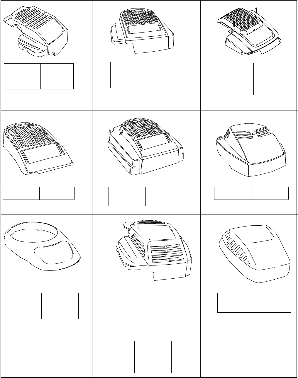
18
Part No.
751B095130
751B2251037
751B281136
751B281145
Description
TT Screw
Control Cover
Rewind Cover
Brake Cover
Shroud Chart
Hardware: 710-1256 (Screw)
Part No.
751B281439
751B281440
751B281443
Color
Dark Red
Black
Bright Red
Hardware: 710-1256
Part No.
731-1395A
731-1396A
731-1397A
Color
Red
Black
Gray
Hardware: 710-1256 (Screw)
Part No.
731-1402A
731-1694
731-1695
731-1934A
Color
Yellow
Black
Silver
Charcoal
Hardware: 7510042823
Part No.
7510143208
Color
Black
Hardware: 7510042823
Part No.
731-1586B
731-1612A
Color
Black
Red
Hardware: 710-1274 (Screw)
Part No.
731-1585B
Color
Black
Part No.
7511681311
7511681911
7511682011
Color
Black
Red
Gray
Hardware: 710-1256 (Screw)
Part No.
751B281451
Color
Gray
Hardware: 710-1237 (Screw)
Part No.
751B281476
751B281777
Color
Black
Yellow
B&S Modular Black Shroud (Not Illustrated)

19
Your Notes
CommentsDate

MANUFACTURER’S LIMITED WARRANTY FOR:
The limited warranty set forth below is given by MTD LLC with
respect to new merchandise purchased and used in the
United States, its possessions and territories.
MTD LLC warrants this product against defects for a period of
two (2) years commencing on the date of original purchase
and will, at its option, repair or replace, free of charge, any
part found to be defective in materials or workmanship. This
limited warranty shall only apply if this product has been
operated and maintained in accordance with the Operator’s
Manual furnished with the product, and has not been subject
to misuse, abuse, commercial use, neglect, accident,
improper maintenance, alteration, vandalism, theft, fire,
water, or damage because of other peril or natural disaster.
Damage resulting from the installation or use of any acces-
sory or attachment not approved by MTD LLC for use with the
product(s) covered by this manual will void your warranty as
to any resulting damage.
Normal wear parts or components thereof are subject to sep-
arate terms as follows: All normal wear parts or component
failures will be covered on the product for a period of 90 days
regardless of cause. After 90 days, but within the two year
period, normal wear part failures will be covered ONLY IF
caused by defects in materials or workmanship of OTHER
component parts. Normal wear parts and components
include, but are not limited to: batteries, belts, blades, blade
adapters, grass bags, rider deck wheels, seats, snow thrower
skid shoes, shave plates, auger spiral rubber, tires.
HOW TO OBTAIN SERVICE: Warranty service is available,
WITH PROOF OF PURCHASE, through your local autho-
rized service dealer. To locate the dealer in your area, check
your Yellow Pages, or contact MTD LLC at P.O. Box 361131,
Cleveland, Ohio 44136-0019, 1-800-800-7310, 1-330-220-
4683 or log on to our Web site at www.mtdproducts.com.
This limited warranty does not provide coverage in the follow-
ing cases:
a. The engine or component parts thereof. These items
carry a separate manufacturer’s warranty. Refer to the
applicable manufacturer’s warranty for terms and condi-
tions.
b. Log splitter pumps, valves, and cylinders have a sepa-
rate one year warranty.
c. Routine maintenance items such as lubricants, filters,
blade sharpening, tune-ups, brake adjustments, clutch
adjustments, deck adjustments, and normal deterioration
of the exterior finish due to use or exposure.
d. MTD LLC does not extend any warranty for products
sold or exported outside of the United States, its posses-
sions and territories, except those sold through MTD
LLC’s authorized channels of export distribution.
e. Parts that are not genuine MTD parts are not covered by
this warranty.
f. Service completed by someone other than an authorized
service dealer is not covered by this warranty.
g. Transportation charges and service calls are not
covered.
No implied warranty, including any implied warranty of
merchantability of fitness for a particular purpose,
applies after the applicable period of express written
warranty above as to the parts as identified. No other
express warranty, whether written or oral, except as men-
tioned above, given by any person or entity, including a
dealer or retailer, with respect to any product, shall bind
MTD LLC. During the period of the warranty, the exclu-
sive remedy is repair or replacement of the product as
set forth above.
The provisions as set forth in this warranty provide the
sole and exclusive remedy arising from the sale. MTD
LLC shall not be liable for incidental or consequential
loss or damage including, without limitation, expenses
incurred for substitute or replacement lawn care services
or for rental expenses to temporarily replace a warranted
product.
Some states do not allow the exclusion or limitation of inci-
dental or consequential damages, or limitations on how long
an implied warranty lasts, so the above exclusions or limita-
tions may not apply to you.
In no event shall recovery of any kind be greater than the
amount of the purchase price of the product sold. Alteration
of safety features of the product shall void this warranty.
You assume the risk and liability for loss, damage, or injury to
you and your property and/or to others and their property
arising out of the misuse or inability to use the product.
This limited warranty shall not extend to anyone other than
the original purchaser or to the person for whom it was pur-
chased as a gift.
HOW STATE LAW RELATES TO THIS WARRANTY: This
limited warranty gives you specific legal rights, and you
may also have other rights which vary from state to state.
MTD LLC, P.O. BOX 361131 CLEVELAND, OHIO 44136-0019 1-800-800-7310
