MTD S 650 652 769 01047 User Manual To The D2db48a1 5409 4b04 A004 A734532ab4cc
User Manual: MTD S 650 652 to the manual
Open the PDF directly: View PDF ![]() .
.
Page Count: 40
PRINTED IN U.S.A.
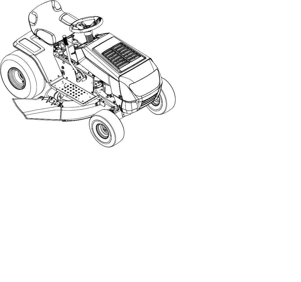
Operator’s Manual
Transmatic Lawn Tractor
MODELS 650
652
Warning: This unit is equipped with an internal combustion engine and should not be used on or near any unimproved forest-covered,
brush-covered or grass-covered land unless the engine’s exhaust system is equipped with a spark arrester meeting applicable local or state
laws (if any). If a spark arrester is used, it should be maintained in effective working order by the operator. In the State of California the
above is required by law (Section 4442 of the California Public Resources Code). Other states may have similar laws. Federal laws apply
on federal lands. A spark arrester for the muffler is available through your nearest engine authorized service dealer or contact the service
department, P.O. Box 361131 Cleveland, Ohio 44136-9722.
MTD LLC, P.O. BOX 361131 CLEVELAND, OHIO 44136-9722
Model 652 Shown
IMPORTANT: Read safety rules and instructions carefully before operating equipment.
FORM NO.
769-01047.fm
(1/08/2004)
2
TABLE OF CONTENTS
FINDING MODEL NUMBER
This Operator’s Manual is an important part of your new lawn tractor. It will help you assemble, prepare and
maintain the unit for best performance. Please read and understand what it says.
Before you start assembling your new equipment, please locate the model plate on the equipment
and copy the information from it in the space provided below. A sample model plate is also given below.
You can locate the model plate by looking at the underside of the seat. This information will be necessary
to use the manufacturer’s web site and/or help from the Customer Support Department or an authorized
service dealer.
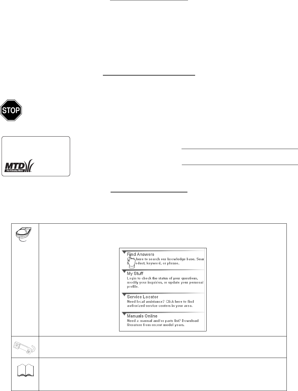
CUSTOMER SUPPORT
Please do NOT return the unit to the retailer without first contacting Customer Support.
If you have difficulty assembling this product or have any questions regarding the controls, operation or
maintenance of this unit, you can seek help from the experts. Choose from the options below:
Visit mtdproducts.com for many useful suggestions. Click on Customer Support button and
you will get the four options reproduced here. Click on the appropriate button and help is
immediately available.
If you prefer to reach a Customer Support Representative, please call (330) 220-4MTD or
1(800) 800-7310.
The engine manufacturer is responsible for all engine-related issues with regard to
performance, power-rating, specifications, warranty and service. Please refer to the engine
manufacturer’s Owner’s/Operator’s Manual, packed separately with your unit, for more
information.
Content Page
Customer Support 2
Important Safe Operation Practices 3
Tractor Set-up 8
Controls 10
Operation 11
Maintenance 16
Service 18
Off-season Storage 22
Attachments & Accessories 23
Parts List 24
Content Page
Copy the model number here:
Copy the serial number here:
www.mtdproducts.com
MTD LLC
P. O. BOX
361131
CLEVELAND,OH
44136
330-220-4683
800-800-7310
The answer you are
looking for could be just
a mouse click away!
The answer you are
looking for could be just
a mouse click away!
Engine
Manual

3
SECTION 1: IMPORTANT SAFE OPERATION PRACTICES
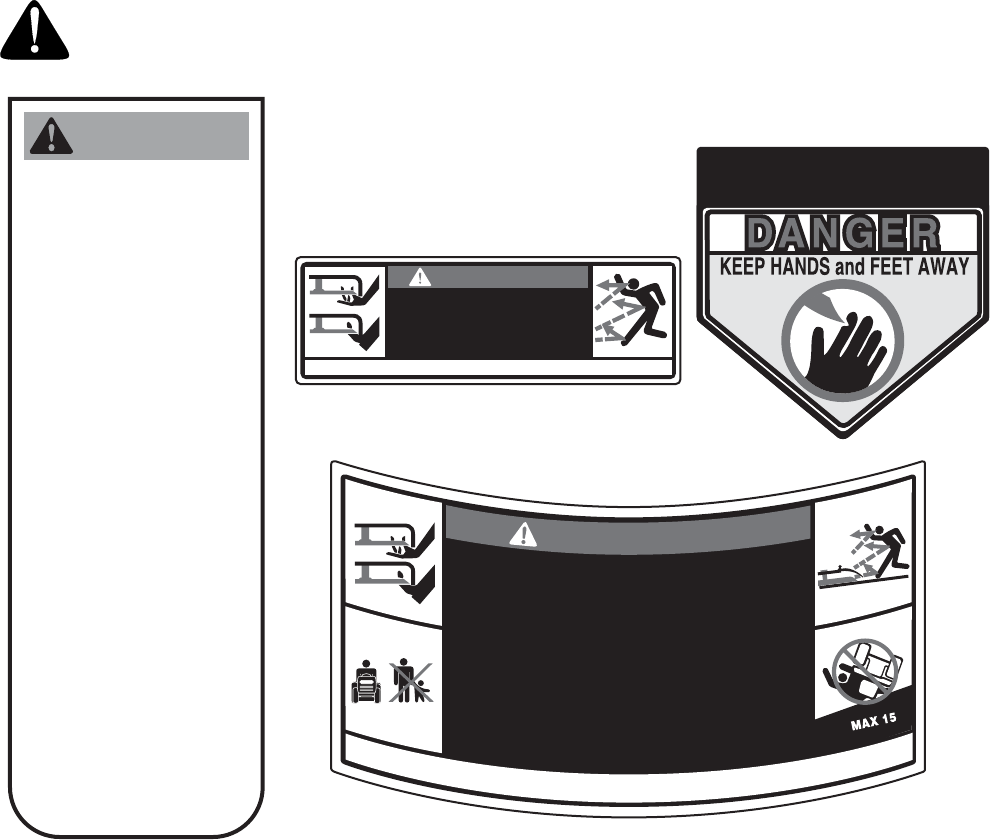
WARNING: This symbol points out important safety instructions which, if not followed, could endanger
the personal safety and/or property of yourself and others. Read and follow all instructions in this manual
before attempting to operate this machine. Failure to comply with these instructions may result in personal
injury. When you see this symbol—heed its warning.
DANGER: This machine was built to be operated according to the rules for safe operation in this man-
ual. As with any type of power equipment, carelessness or error on the part of the operator can result in
serious injury. This machine is capable of amputating hands and feet and throwing objects. Failure to
observe the following safety instructions could result in serious injury or death.
WARNING: Engine exhaust, some of its constituents, and certain vehicle components contain
or emit chemicals known to the State of California to cause cancer and birth defects or other
reproductive harm.
GENERAL OPERATION
1. Read, understand, and follow all instructions on the
machine and in the manual(s) before attempting to
assemble and operate. Keep this manual in a safe
place for future and regular reference and for
ordering replacement parts.
2. Be familiar with all controls and their proper
operation. Know how to stop the machine and
disengage them quickly.
3. Never allow children under 14 years old to operate
this machine. Children 14 years old and over
should read and understand the operation
instructions and safety rules in this manual and
should be trained and supervised by a parent.
4. Never allow adults to operate this machine without
proper instruction.
5. To help avoid blade contact or a thrown object
injury, keep bystanders, helpers, children and pets
at least 75 feet from the machine while it is in
operation. Stop machine if anyone enters the area.
6. Thoroughly inspect the area where the equipment
is to be used. Remove all stones, sticks, wire,
bones, toys, and other foreign objects which could
be picked up and thrown by the blade(s). Thrown
objects can cause serious personal injury.
7. Plan your mowing pattern to avoid discharge of
material toward roads, sidewalks, bystanders and
the like. Also, avoid discharging material against a
wall or obstruction which may cause discharged
material to ricochet back toward the operator.
8. Always wear safety glasses or safety goggles
during operation and while performing an
adjustment or repair to protect your eyes. Thrown
objects which ricochet can cause serious injury to
the eyes.
9. Wear sturdy, rough-soled work shoes and close-
fitting slacks and shirts. Loose fitting clothes and
jewelry can be caught in movable parts. Never
operate this machine in bare feet or sandals.
10. Be aware of the mower and attachment discharge
direction and do not point it at anyone. Do not
operate the mower without the discharge cover or
entire grass catcher in its proper place.
11. Do not put hands or feet near rotating parts or
under the cutting deck. Contact with the blade(s)
can amputate hands and feet.
12. A missing or damaged discharge cover can cause
blade contact or thrown object injuries.
13. Stop the blade(s) when crossing gravel drives,
walks, or roads and while not cutting grass.
14. Watch for traffic when operating near or crossing
roadways. This machine is not intended for use on
any public roadway.
15. Do not operate the machine while under the
influence of alcohol or drugs.
16. Mow only in daylight or good artificial light.
17. Never carry passengers.
18. Disengage blade(s) before shifting into reverse.
Back up slowly. Always look down and behind
before and while backing to avoid a back-over
accident.
19. Slow down before turning. Operate the machine
smoothly. Avoid erratic operation and excessive
speed.
20. Disengage blade(s), set parking brake, stop engine
and wait until the blade(s) come to a complete stop
before removing grass catcher, emptying grass,
unclogging chute, removing any grass or debris, or
making any adjustments.
21. Never leave a running machine unattended.
Always turn off blade(s), place transmission in
neutral, set parking brake, stop engine and remove
key before dismounting.
22. Use extra care when loading or unloading the
machine into a trailer or truck. This unit should not
be driven up or down ramp(s), because the unit
could tip over, causing serious personal injury. The
unit must be pushed manually on ramp(s) to load or
unload properly.
4
23. Muffler and engine become hot and can cause a
burn. Do not touch.
24. Check overhead clearances carefully before driving
under low hanging tree branches, wires, door
openings etc., where the operator may be struck or
pulled from the unit, which could result in serious
injury.
25. Disengage all attachment clutches, depress the
brake pedal completely and shift into neutral before
attempting to start engine.
26. Your machine is designed to cut normal residential
grass of a height no more than 10”. Do not attempt
to mow through unusually tall, dry grass (e.g.,
pasture) or piles of dry leaves. Dry grass or leaves
may contact the engine exhaust and/or build up on
the mower deck presenting a potential fire hazard.
27. Use only accessories and attachments approved
for this machine by the machine manufacturer.
Read, understand and follow all instructions
provided with the approved accessory or
attachment.
28. Data indicates that operators, age 60 years and
above, are involved in a large percentage of riding
mower-related injuries. These operators should
evaluate their ability to operate the riding mower
safely enough to protect themselves and others
from serious injury.
29. If situations occur which are not covered in this
manual, use care and good judgment. Contact your
customer service representative for assistance.
SLOPE OPERATION
Slopes are a major factor related to loss of control and
tip-over accidents which can result in severe injury or
death. All slopes require extra caution. If you cannot
back up the slope or if you feel uneasy on it, do not mow
it.
For your safety, use the slope gauge included as part of
this manual to measure slopes before operating this
unit on a sloped or hilly area. If the slope is greater than
15 degrees as shown on the slope gauge, do not
operate this unit on that area or serious injury could
result.
DO:
1. Mow up and down slopes, not across. Exercise
extreme caution when changing direction on
slopes.
2. Watch for holes, ruts, bumps, rocks, or other
hidden objects. Uneven terrain could overturn the
machine. Tall grass can hide obstacles.
3. Use slow speed. Choose a low enough speed
setting so that you will not have to stop or shift while
on the slope. Tires may lose traction on slopes
even though the brakes are functioning properly.
Always keep machine in gear when going down
slopes to take advantage of engine braking action.
4. Follow the manufacturer’s recommendations for
wheel weights or counterweights to improve
stability.
5. Use extra care with grass catchers or other
attachments. These can change the stability of the
machine.
6. Keep all movement on the slopes slow and gradual.
Do not make sudden changes in speed or direction.
Rapid engagement or braking could cause the front
of the machine to lift and rapidly flip over backwards
which could cause serious injury.
7. Avoid starting or stopping on a slope. If tires lose
traction, disengage the blade(s) and proceed
slowly straight down the slope.
DO NOT:
1. Do not turn on slopes unless necessary; then, turn
slowly and gradually downhill, if possible.
2. Do not mow near drop-offs, ditches or
embankments. The mower could suddenly turn
over if a wheel is over the edge of a cliff, ditch, or if
an edge caves in.
3. Do not try to stabilize the machine by putting your
foot on the ground.
4. Do not use a grass catcher on steep slopes.
5. Do not mow on wet grass. Reduced traction could
cause sliding.
6. Do not shift to neutral and coast downhill. Over-
speeding may cause the operator to lose control of
the machine resulting in serious injury or death.
7. Do not tow heavy pull behind attachments (e.g.
loaded dump cart, lawn roller, etc.) on slopes
greater than 5 degrees. When going down hill, the
extra weight tends to push the tractor and may
cause you to loose control. (e.g. tractor may speed
up, braking and steering ability are reduced,
attachment may jack-knife and cause tractor to
overturn).
CHILDREN
1. Tragic accidents can occur if the operator is not
alert to the presence of children. Children are often
attracted to the machine and the mowing activity.
They do not understand the dangers. Never
assume that children will remain where you last
saw them.
a. Keep children out of the mowing area and in
watchful care of a responsible adult other
than the operator.
b. Be alert and turn machine off if a child enters
the area.
5
c. Before and while backing, look behind and
down for small children.
d. Never carry children, even with the blade(s)
shut off. They may fall off and be seriously
injured or interfere with safe machine
operation.
e. Use extreme care when approaching blind
corners, doorways, shrubs, trees or other
objects that may block your vision of a child
who may run into the machine.
f. Disengage the cutting blade(s) before
shifting in reverse. The “No-Cut-In Reverse”
feature is a reminder not to cut in reverse and
to help avoid back over accidents. Do not
defeat it.
g. Keep children away from hot or running
engines. They can suffer burns from a hot
muffler.
h. Remove key when machine is unattended to
prevent unauthorized operation.
9. Never allow children under 14 years old to operate
the machine. Children 14 years old and over should
read and understand the operation instructions and
safety rules in this manual and should be trained
and supervised by a parent.
TOWING
1. Tow only with a machine that has a hitch designed
for towing. Do not attach towed equipment except
at the hitch point.
2. Follow the manufacturers recommendation for
weight limits for towed equipment and towing on
slopes.
3. Never allow children or others in or on towed
equipment.
4. On slopes, the weight of the towed equipment may
cause loss of traction and loss of control.
5. Travel slowly and allow extra distance to stop.
6. Do not shift to neutral and coast downhill.
SERVICE
SAFE HANDLING OF GASOLINE:
1. To avoid personal injury or property damage
use extreme care in handling gasoline. Gasoline is
extremely flammable and the vapors are explosive.
Serious personal injury can occur when gasoline is
spilled on yourself or your clothes which can ignite.
Wash your skin and change clothes immediately.
a. Use only an approved gasoline container.
b. Never fill containers inside a vehicle or on a
truck or trailer bed with a plastic liner. Always
place containers on the ground away from
your vehicle before filling.
c. When practical, remove gas-powered
equipment from the truck or trailer and refuel
it on the ground. If this is not possible, then
refuel such equipment on a trailer with a
portable container, rather than from a
gasoline dispenser nozzle.
d. Keep the nozzle in contact with the rim of the
fuel tank or container opening at all times
until fueling is complete. Do not use a nozzle
lock-open device.
e. Extinguish all cigarettes, cigars, pipes and
other sources of ignition.
f. Never fuel machine indoors.
g. Never remove gas cap or add fuel while the
engine is hot or running. Allow engine to cool
at least two minutes before refueling.
h. Never over fill fuel tank. Fill tank to no more
than ½ inch below bottom of filler neck to
allow space for fuel expansion.
i. Replace gasoline cap and tighten securely.
j. If gasoline is spilled, wipe it off the engine
and equipment. Move unit to another area.
Wait 5 minutes before starting the engine.
k. To reduce fire hazards, keep machine free of
grass, leaves, or other debris build-up. Clean
up oil or fuel spillage and remove any fuel
soaked debris.
l. Never store the machine or fuel container
inside where there is an open flame, spark or
pilot light as on a water heater, space heater,
furnace, clothes dryer or other gas
appliances.
m. Allow a machine to cool at least five minutes
before storing.
GENERAL SERVICE:
1. Never run an engine indoors or in a poorly
ventilated area. Engine exhaust contains carbon
monoxide, an odorless, and deadly gas.
2. Before cleaning, repairing, or inspecting, make
certain the blade(s) and all moving parts have
stopped. Disconnect the spark plug wire and
ground against the engine to prevent unintended
starting.
3. Periodically check to make sure the blades come to
complete stop within approximately (5) five
seconds after operating the blade disengagement
control. If the blades do not stop within the this time
frame, your unit should be serviced professionally
by an authorized MTD Service Dealer.
4. Check brake operation frequently as it is subjected
to wear during normal operation. Adjust and service
as required.
5. Check the blade(s) and engine mounting bolts at
frequent intervals for proper tightness. Also,
visually inspect blade(s) for damage (e.g.,
excessive wear, bent, cracked).
6
Replace the blade(s) with the original equipment
manufacturer’s (O.E.M.) blade(s) only, listed in this
manual. “Use of parts which do not meet the
original equipment specifications may lead to
improper performance and compromise safety!”
6. Mower blades are sharp. Wrap the blade or wear
gloves, and use extra caution when servicing them.
7. Keep all nuts, bolts, and screws tight to be sure the
equipment is in safe working condition.
8. Never tamper with the safety interlock system or
other safety devices. Check their proper operation
regularly.
9. After striking a foreign object, stop the engine,
disconnect the spark plug wire(s) and ground
against the engine. Thoroughly inspect the
machine for any damage. Repair the damage
before starting and operating.
10. Never attempt to make adjustments or repairs to
the machine while the engine is running.
11. Grass catcher components and the discharge
cover are subject to wear and damage which could
expose moving parts or allow objects to be thrown.
For safety protection, frequently check components
and replace immediately with original equipment
manufacturer’s (O.E.M.) parts only, listed in this
manual. “Use of parts which do not meet the
original equipment specifications may lead to
improper performance and compromise safety!”
12. Do not change the engine governor settings or
over-speed the engine. The governor controls the
maximum safe operating speed of the engine.
13. Maintain or replace safety and instruction labels, as
necessary.
14. Observe proper disposal laws and regulations for
gas, oil, etc. to protect the environment.
WARNING: YOUR RESPONSIBILITY- Restrict the use of this power machine to persons who
read, understand and follow the warnings and instructions in this manual and on the machine.
WARNING
• GO UP AND DOWN SLOPES, NOT ACROSS.
• AVOID SUDDEN TURNS.
• DO NOT OPERATE THE UNIT WHERE IT
COULD SLIP OR TIP.
• IF MACHINE STOPS GOING UPHILL, STOP
BLADE(S) AND BACK DOWNHILL SLOWLY.
• DO NOT MOW WHEN CHILDREN
OR OTHERS ARE AROUND.
• NEVER CARRY CHILDREN EVEN WITH
BLADES OFF.
• LOOK DOWN & BEHIND BEFORE AND
WHILE BACKING.
• KEEP SAFETY DEVICES (GUARDS,
SHIELDS, AND SWITCHES, ETC.)
IN PLACE AND WORKING.
• REMOVE OBJECTS THAT COULD
BE THROWN BY THE BLADE(S).
• KNOW LOCATION AND FUNCTION OF ALL
CONTROLS.
• BE SURE BLADE(S) AND ENGINE ARE
STOPPED BEFORE PLACING HANDS
OR FEET NEAR BLADE(S).
• BEFORE LEAVING OPERATOR'S POSITION,
DISENGAGE BLADE(S), PLACE THE CONTROL
LEVER IN NEUTRAL, ENGAGE PARKING
BRAKE, SHUT OFF AND REMOVE KEY.
TO AVOID SERIOUS
INJURY OR DEATH
READ OPERATOR'S
MANUAL
DANGER
KEEP HANDS AND FEET AWAY.
DO NOT OPERATE MOWER
UNLESS CHUTE DEFLECTOR
OR ENTIRE GRASS CATCHER IS
IN ITS PROPER PLACE.
ASSEMBLE CHUTE DEFLECTOR TO THIS UNIT BEFORE OPERATING.
S30503
TO REDUCE THE RISK OF INJURY, DO NOT
OPERATE UNLESS DISCHARGE COVER OR
GRASS CATCHER IS IN ITS PROPER PLACE.
IF DAMAGED, REPLACE IMMEDIATELY.
D
A
N
G
E
R
•
K
E
E
P
H
A
N
D
S
A
N
D
F
E
E
T
A
W
A
Y
F
R
O
M
A
V
O
I
D
S
E
R
I
O
U
S
I
N
J
U
R
Y
O
R
D
E
A
T
H
R
O
T
A
T
I
N
G
P
A
R
T
S
•
R
E
M
O
V
E
O
B
J
E
C
T
S
T
H
A
T
C
A
N
B
E
T
H
R
O
W
N
B
Y
T
H
E
B
L
A
D
E
I
N
A
N
Y
D
I
R
E
C
T
I
O
N
.
W
E
A
R
S
A
F
E
T
Y
G
L
A
S
S
E
S
.
•
D
O
N
O
T
M
O
W
W
H
E
N
C
H
I
L
D
R
E
N
O
R
O
T
H
E
R
S
A
R
E
A
R
O
U
N
D
.
N
E
V
E
R
C
A
R
R
Y
C
H
I
L
D
R
E
N
E
V
E
N
W
I
T
H
B
L
A
D
E
S
O
F
F
.
.
•
U
S
E
E
X
T
R
A
C
A
U
T
I
O
N
O
N
S
L
O
P
E
S
.
D
O
N
O
T
M
O
W
S
L
O
P
E
S
G
R
E
A
T
E
R
T
H
A
N
1
5
˚
.
M
O
W
U
P
A
N
D
D
O
W
N
,
N
O
T
A
C
R
O
S
S
.
A
V
O
I
D
S
U
D
D
E
N
T
U
R
N
S
.
U
S
E
L
O
W
S
P
E
E
D
.
R
E
A
D
O
P
E
R
A
T
O
R
'
S
M
A
N
U
A
L
.
K
E
E
P
S
A
F
E
T
Y
D
E
V
I
C
E
S
I
N
P
L
A
C
E
A
N
D
W
O
R
K
I
N
G
.
S30018
7
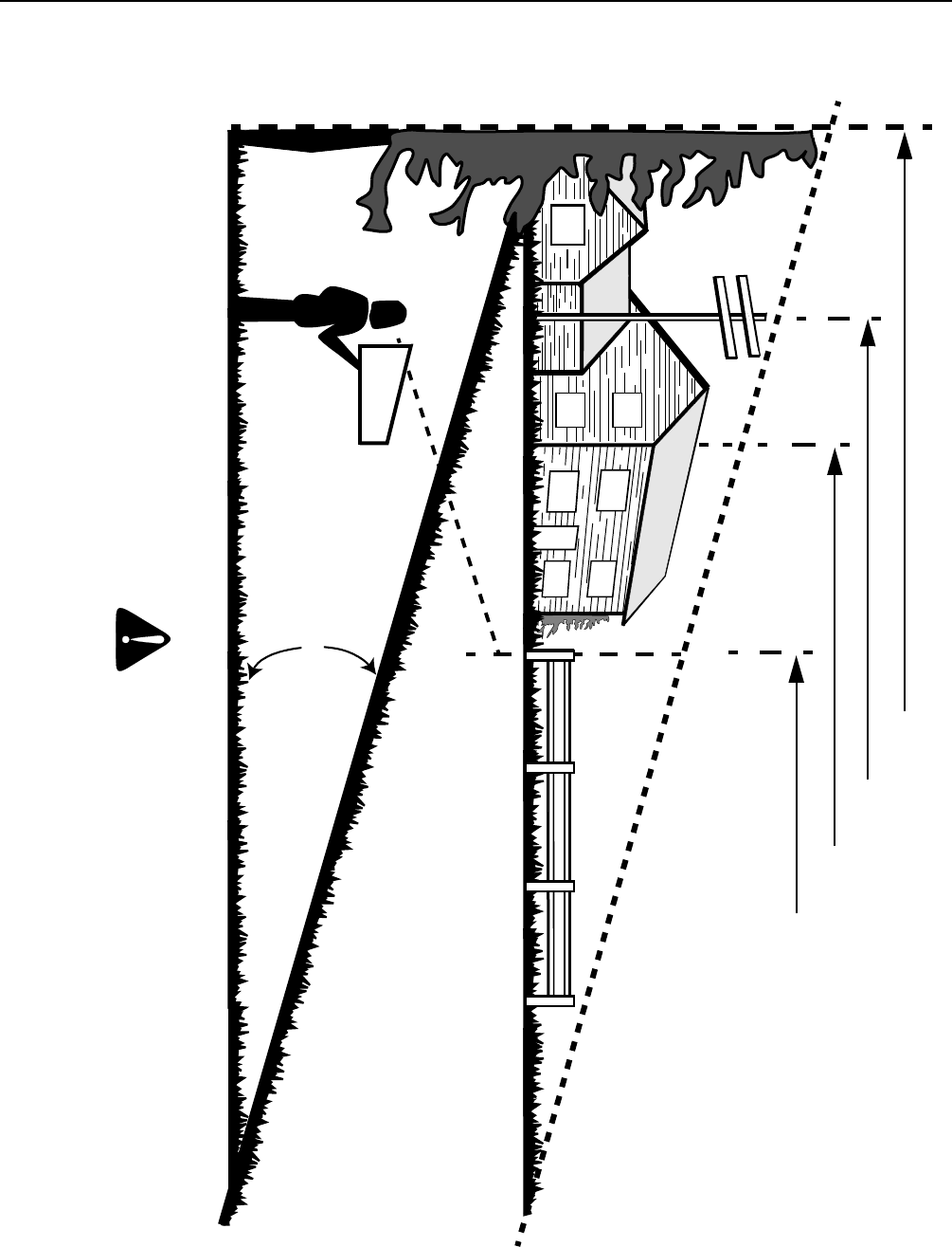
SECTION 2: SLOPE GAUGE
15°
SIGHT AND HOLD THIS LEVEL WITH A VERTICAL TREE
A POWER POLE
A CORNER OF A BUILDING
OR A FENCE POST
FOLD ON DOTTED LINE, REPRESENTING A 15° SLOPE
Do not mow on inclines with a slope in excess of 15 degrees (a rise of approximately 2-1/2 feet every 10 feet). A riding mower
could overturn and cause serious injury. If operating a walk-behind mower on such a slope, it is extremely difficult to maintain
your footing and you could slip, resulting in serious injury.
Operate RIDING mowers up and down slopes, never across the face of slopes.
WARNING
8
SECTION 3: TRACTOR SET-UP
NOTE: Reference to right or left hand side of the unit
is observed from the driver’s seat, facing forward.
Tools Required For Assembly
(1) 1/2" socket wrench (for steering wheel)
(1) 9/16" wrench or socket wrench (for seat)
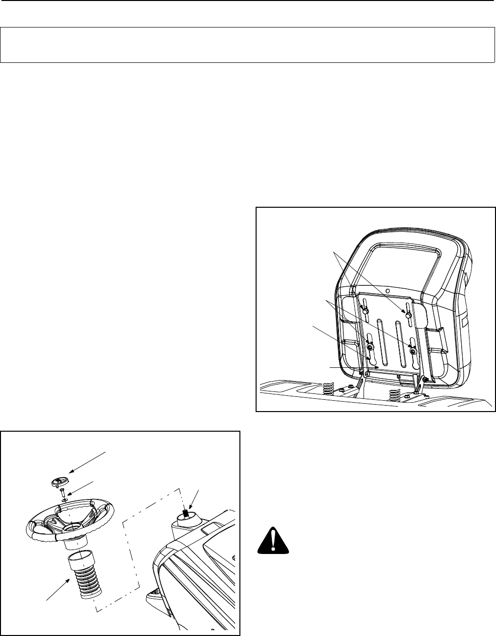
Attaching The Steering Wheel
• The hardware for attaching the steering wheel has
been packed within the steering wheel, beneath
steering wheel cap. Carefully pry off the steering
wheel cap and remove the hardware.
• Remove the steering bellow from its packaged
location on the deck engagement/lift lever (found
on the right hand side of tractor).
• Place the steering bellow over the steering shaft
extending through the dash. See Figure 1.
NOTE: If the openings on each end of the steering
bellow are two different sizes, the smaller end goes
down, against the dash of the lawn tractor.
•With the wheels of the tractor pointing straight
forward, place the steering wheel over the steering
shaft.
• Place the washer (with the cupped side down) over
the steering shaft and secure with the hex bolt. See
Figure 1.
• Place the steering wheel cap over the center of the
steering wheel and push downward until it “clicks”
into place.
Figure 1
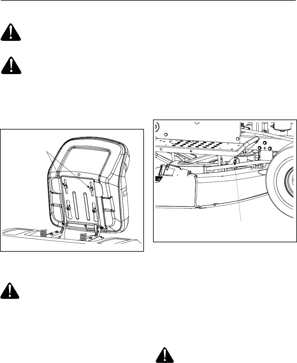
Attaching The Seat
NOTE: For shipping reasons, seats are either
fastened to the tractor seat’s pivot bracket with a plastic
tie, or mounted backward to the pivot bracket. In either
case, free the seat form its shipping position and
remove the two hex screws from the bottom of seat
before proceeding with instructions below.
1. Position the shoulder screws (found on the base of
the seat) inside the slot openings in the seat pivot
bracket. Figure 2.
Figure 2
2. Slide the seat slightly rearward in the seat pivot
bracket, lining up the rear slots in the pivot bracket
with the remaining two holes in the seat’s base.
3. Select desired position for the seat, and secure with
the two hex screws removed earlier. See Figure 2.
Tire Pressure
WARNING: Maximum tire pressure under
any circumstances is 30 psi. Equal tire
pressure should be maintained at all times.
The tires on your unit may be over-inflated for shipping
purposes. Reduce the tire pressure before operating
the tractor. Recommended operating tire pressure is
approximately 10 p.s.i for the rear tires & 14 p.s.i. for
the front tires. Check sidewall of tire for maximum p.s.i.
IMPORTANT:
Your tractor is shipped with motor oil in the engine. However, you MUST check the oil level before
starting the engine and operating. Refer to the separate Briggs & Stratton Operator/Owner Manual (or Tecumseh
engine’s Owner’s Manual) packed with your tractor. Read instructions carefully.
Steering
Hex Bolt Steering
Shaft
Steering
Bellow
& Washer
Wheel Cap
Hex Screws
Shoulder
Screws
Opening
in Slot
Pivot Bracket
9
Gas and Oil Fill-up
The gasoline tank is located under the hood and has a
capacity of one and-a-half gallons. Do not overfill.
WARNING: Use extreme care when
handling gasoline. Gasoline is extremely
flammable and the vapors are explosive.
Never fuel machine indoors or while the
engine is hot or running. Extinguish
cigarettes, cigars, pipes, and other sources of
ignition.
Service the engine with gasoline and oil as instructed in
the separate Briggs & Stratton Operator/Owner Manual
(or Tecumseh engine’s Owner’s Manual) packed with
your tractor. Read instructions carefully.
IMPORTANT:
Your tractor is shipped with motor oil in the
engine. However, you MUST check the oil level before
operating. Be careful not to overfill.
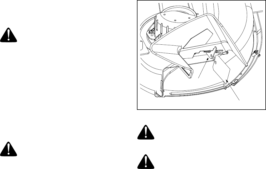
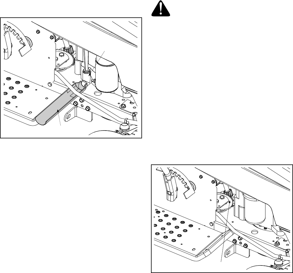
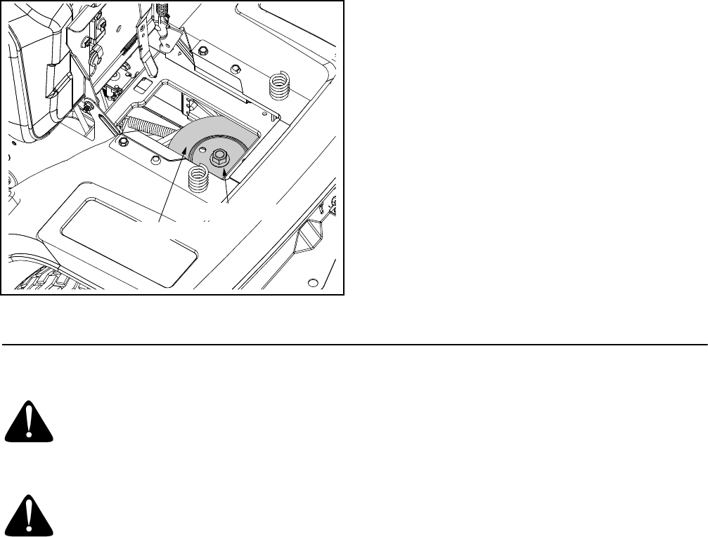
Shipping Brace Removal
WARNING: Make sure the riding mower’s
engine is off, remove the ignition key, and set
the parking brake before removing the
shipping brace.
• Locate the shipping brace and accompanying
warning tag found on the right side of the mower,
between the discharge chute and the cutting deck.
See Figure 3.
• While holding the discharge chute with your left
hand, remove the shipping brace with your right
hand by grasping it between your thumb and index
finger and rotating it clockwise.
Figure 3
WARNING: The shipping brace, used for
packaging purposes only, must be removed
and discarded before operating your riding
mower.
WARNING: The mowing deck is capable of
throwing objects. Failure to operate the riding
mower without the discharge cover in the
proper operating position could result in
serious personal injury and/or property
damage.
Shipping Brace
Warning Tag
10
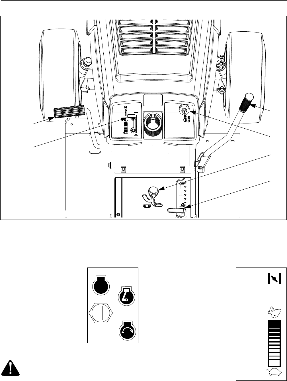
SECTION 4: KNOW YOUR LAWN TRACTOR
Figure 4
Ignition Switch
The ignition switch is located on
the right side of the tractor’s
dash.To start the engine, insert
the key into the ignition switch
and turn clockwise to the START
position. Release the key into the
ON position once engine has
fired.
Refer to Starting The Engine on
page 12 of this manual for
detailed starting instructions
WARNING: Never leave a running
machine unattended. Always disengaged
PTO, Shift into neutral, set parking brake,
stop engine and remove key to prevent
unintended starting.
Throttle Control Lever
The throttle control lever is
located on the left side of the
tractor’s dash panel. This lever
controls the speed of the engine
and, when pushed all the way
forward, the choke control also.
When set in a given position, the
throttle will maintain a uniform
engine speed.
Refer to Starting The Engine on
page 12 of this manual for
detailed starting instructions
IMPORTANT:
When operating the
tractor with the cutting deck
engaged, be certain that the
throttle lever is always in the FAST (rabbit) position.
AClutch-brake Pedal DIgnition Switch
BThrottle Control Lever EShift Lever
CDeck Engagement / Lift Lever FSpeed Control Lever / Parking Brake
B
A
C
D
F
E
NOTE: Steering Wheel not shown for clarity.
STOP
RUN
START
STOP
Slow
Choke
Fast
Position
Position
Position
11
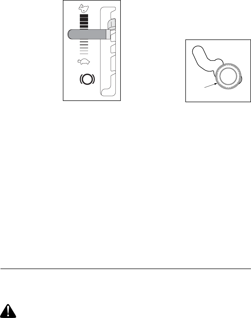
Speed Control Lever
The speed control lever,
located on the right side of
the center console, allows
you to regulate the ground
speed of the lawn tractor.
To use, depress the clutch-
brake pedal and move the
lever out of the parking
brake notch and forward to
increase the tractor’s
ground speed. When a
desired speed has been
reached, release the lever
into an appropriate notch to
maintain that speed.
To slow the tractor’s
ground speed, depress the clutch-brake pedal and
move the speed control lever rearward and release it
into a notch.
Clutch-brake Pedal
The clutch-brake pedal is located on the left side of the
lawn tractor, along the running board. Depress the
clutch-brake pedal part way down when slowing the
tractor by changing speeds (Refer to Speed Control Lever).
Depress the pedal all the way down to engage the disc
brake and bring the tractor to a complete stop.
NOTE: The pedal must be depressed to start the
engine. Refer to Safety Interlock Switches on page 11.
Parking Brake
To set the parking brake, fully depress the clutch-brake
pedal. Move the speed control lever all the way to the
rear and release it into the parking brake position.
Release the clutch-brake pedal to allow the parking
brake to engage.
To release the parking brake, depress the clutch-brake
pedal and move the speed control lever out of the
notches to the desired position. Release the speed
control lever and the clutch-brake pedal.
NOTE: The parking brake must be set if the operator
leaves the seat with the engine running or the engine
will automatically shut off.
IMPORTANT:
Always set the parking brake when
leaving the tractor unattended.
Shift Lever
The shift lever is
located in the center of
the console and has
three positions, F
(Forward), N (Neutral)
and R (Reverse). See
Figure 4. The clutch-
brake pedal must be
fully depressed and the
tractor must not be in
motion when the moving shift lever.
IMPORTANT:
Never force the shift lever. Doing so may
result in serious damage to the tractor’s transmission.
NOTE: If difficulty is encountered while attempting to
shift, release the clutch-brake pedal slightly before fully
depressing the pedal again.
Deck Engagement / Lift Lever
Found on the right side of the tractor, the deck
engagement/lift lever is used to set the mowing deck’s
cutting height and engage the power to the cutting deck
or other (separately available) attachments. To
operate, move the lever to the right and forward, before
placing it a notch for your desired cutting height. Moving
the lever to the right and all the way rearward placing it
into the BLADES STOP position disengages power to
the cutting deck/ attachment.
NOTE: The deck engagement/lift lever must be in the
disengaged (BLADES STOP) position when starting
the engine, when traveling in reverse and if the operator
leaves the seat.
SECTION 5: OPERATING THE LAWN TRACTOR
Safety Interlock System
WARNING: Read, understand, and follow
all instructions and warnings on the machine
and in this manual before operating.
This tractor is equipped with a safety interlock system
for the protection of the operator. If the interlock system
should ever malfunction, do not operate the tractor.
Contact an authorized MTD service dealer. The safety
interlock system prevents the engine from cranking or
starting unless the parking brake is engaged, and the
deck engagement/lift lever is in the disengaged
(BLADES STOP) position.
• The engine will automatically shut off if the operator
leaves the seat before engaging the parking brake.
P
5
4
3
2
1
F
N
R
Shift
Knob
12
• The engine will automatically shut off if the operator
leaves the tractor’s seat with the deck engagement/
lift lever in ANY position other than BLADES STOP.
• The engine will automatically shut off if the deck
engagement/lift lever is moved out of the BLADES
STOP position with the shift lever in R (reverse).
Before Starting Engine
WARNING: Read, understand, and follow
all instructions and warnings on the machine
and in this manual before operating.
Starting the Engine
WARNING: Do not operate the tractor if the
interlock system is malfunctioning. This
system was designed for your safety and
protection.
NOTE: Refer to the TRACTOR SET-UP on page 8 of this
manual for Gasoline and Oil fill-up instructions.
• Insert the tractor key into the ignition switch.
• Place the deck engagement/lift lever in the
BLADES STOP position.
• Engage the tractor’s parking brake.
• Activate the choke control.
• Turn the ignition key clockwise to the START
position. After the engine starts, release the key. It
will return to the ON position.
IMPORTANT:
Do NOT hold the key in the START
position for longer than ten seconds at a time. Doing so
may cause damage to your engine’s electric starter.
• After the engine starts, move the throttle control
into the FAST position.
IMPORTANT:
Do NOT leave the choke control on while
operating the tractor. Doing so will result in a "rich" fuel
mixture and cause the engine to run poorly.
NOTE: If Starting problems are encountered, refer to
TROUBLE SHOOTING GUIDE on page 23.
Stopping the Engine
WARNING: If you strike a foreign object,
stop the engine, disconnect the spark plug
wire(s) and ground against the engine.
Thoroughly inspect the machine for any
damage. Repair the damage before restarting
and operating
• If the blades are engaged, place the deck
engagement/lift lever in the BLADES STOP
position.
• Depress the clutch-brake pedal to bring the tractor
to a complete stop.
• Turn the ignition key counterclockwise to the OFF
position.
• Engage the tractor’s parking brake.
• Remove the key from the ignition switch to prevent
unintended starting.
Operating The Lawn Tractor
WARNING: Always look down and behind
before and while backing up to avoid a back-
over accident.
WARNING: Before leaving the operator’s
position. Always place the deck engagement/
lift lever in the BLADES STOP position, shift
into neutral, set parking brake, stop engine
and remove key to prevent unintended
starting.
• Move throttle control lever to full throttle.
NOTE: Always operate the tractor with the throttle
control lever in the FAST (rabbit) position for the most
efficient use of the cutting deck or other (separately
available) attachments.
• Place the shift lever in either the FORWARD or
REVERSE position.
• Release the parking brake by depressing the
clutch-brake pedal and positioning the speed
control lever in desired position.
IMPORTANT:
First-time operators should use speed
positions 1 or 2. Become completely familiar with the
tractor’s operation and controls before operating the
tractor in higher speed positions.
WARNING
AVOID SERIOUS INJURY OR DEATH
• GO UP AND DOWN SLOPES, NOT ACROSS.
• AVOID SUDDEN TURNS.
• DO NOT OPERATE THE UNIT WHERE IT COULD SLIP OR
TIP.
• IF MACHINE STOPS GOING UPHILL, STOP BLADE(S) AND
BACK DOWNHILL SLOWLY.
• DO NOT MOW WHEN CHILDREN OR OTHERS ARE
AROUND.
• NEVER CARRY CHILDREN, EVEN WITH BLADES OFF.
• LOOK DOWN AND BEHIND BEFORE AND WHILE BACKING.
• KEEP SAFETY DEVICES (GUARDS, SHIELDS, AND
SWITCHES) IN PLACE AND WORKING.
• REMOVE OBJECTS THAT COULD BE THROWN BY THE
BLADE(S).
• KNOW LOCATION AND FUNCTION OF ALL CONTROLS.
• BE SURE BLADE(S) AND ENGINE ARE STOPPED BEFORE
PLACING HANDS OR FEET NEAR BLADE(S).
• BEFORE LEAVING OPERATOR’S POSITION, DISENGAGE
BLADE(S), PLACE THE SHIFT LEVER IN NEUTRAL, ENGAGE
PARKING BRAKE, SHUT ENGINE OFF AND REMOVE KEY.
READ OPERATOR’S MANUAL

13
• Release clutch-brake pedal slowly to put unit into
motion.
• The lawn tractor is brought to a stop by depressing
the clutch-brake pedal.
NOTE: When operating the unit initially, there will be
little difference between the highest two speeds until
after the belts have seated themselves into the pulleys
during the break-in period.
WARNING: Before leaving the operator’s
position for any reason, disengage the
blades, place the shift lever in neutral,
engage the parking brake, shut engine off
and remove the key.
IMPORTANT:
When stopping the tractor for any reason
while on a grass surface, always
• Place the shift lever in neutral,
• Engage the parking brake,
• Shut engine off and remove the key.
Doing so will minimize the possibility of having your
lawn ‘‘browned’’ by hot exhaust from your tractor’s
running engine.
If unit stalls with speed control in high speed, or if unit
will not operate with speed control lever in a low speed
position, proceed as follows.
• Place shift lever in NEUTRAL.
• Restart engine.
• Place speed control lever in high speed position.
• Release clutch-brake pedal fully.
• Depress clutch-brake pedal.
• Place speed control lever in desired position.
• Place shift lever in either FORWARD or REVERSE,
and follow normal operating procedures.
Engaging The Cutting Blades
WARNING: Keep feet and hands away
from the discharge opening, the blades or
any part of the deck. When the unit is used
for anything other than mowing operations,
the blade drive should be disengaged.
To engage power to the cutting deck or other
(separately available) attachment, proceed as follows:
• Move the deck engagement/lift lever to the right
and forward,
• Place the lever a notch for your desired cutting
height.
• Moving the lever to the right and all the way
rearward placing it into the BLADES STOP position
raises and disengages power to the cutting deck.
NOTE: The deck engagement/lift lever must be in the
disengaged (BLADES STOP) position when starting
the engine, when traveling in reverse and if the operator
leaves the seat. Refer to Safety Interlock Switches on page
11
Mowing
WARNING: To help avoid blade contact or
a thrown object injury, keep bystanders,
helpers, children and pets at least 75 feet
from the machine while it is in operation. Stop
machine if anyone enters the area.
The following information will be helpful when using the
cutting deck with your tractor.
WARNING: Plan your mowing pattern to
avoid discharge of materials toward roads,
sidewalks, bystanders and the like. Also,
avoid discharging material against a wall or
obstruction which may cause discharged
material to ricochet back toward the operator.
• Be sure that the lawn is clear of stones, sticks, wire,
or other objects which could damage lawn mower
or engine.
• For best results and to insure more even grass
distribution, do not mow when lawn is excessively
wet.
• Do not mow at high ground speed, especially if a
mulch kit or grass collector is installed.
• For best results it is recommended that the first two
laps be cut with the discharge thrown towards the
center. After the first two laps, reverse the direction
to throw the discharge to the outside for the
balance of cutting. This will give a better
appearance to the lawn.
• Do not cut the grass too short. Short grass invites
weed growth and yellows quickly in dry weather.
• Mowing should always be done with the engine at
full throttle.
• Under heavier conditions it may be necessary to go
back over the cut area a second time to get a clean
cut.
• Do NOT attempt to mow heavy brush and weeds
and extremely tall grass. Your tractor is designed to
mow lawns, NOT clear brush.
• Keep the blades sharp and replace the blades
when worn. Refer to Cutting Blades on page 19 of this
manual for proper blade sharpening instructions.
14
SECTION 6: MAKING ADJUSTMENTS
WARNING: Never attempt to make any
adjustments while the engine is running,
except where specified in the operator’s
manual.
WARNING: Disconnect the spark plug
wire(s) and ground against the engine before
performing any adjustments, repairs or
maintenance.
Seat Adjustment
To adjust the position of the seat, loosen the two hex
screws on the bottom of the seat. See Figure 5. Slide
the seat forward or backward as desired. Retighten the
two screws.
Figure 5
Deck Leveling Adjustment
WARNING: Protect your hands by wearing
heavy gloves to grasp the cutting blade.
NOTE: Check the tractor’s tire pressure before
performing any deck leveling adjustments. Refer to
Tires later in this section for further information
regarding tire pressure.
The front of the cutting deck is supported by two lift
links, one of which can be adjusted to level the deck
from both front to rear & side to side. The front of the
deck should be between 1/4-inch and 3/8-inch lower
than the rear of the deck. Adjust if necessary as follows:
• With the tractor parked on a firm, level surface,
place the deck engagement/lift lever in the top
cutting height notch (not BLADES STOP) position.
• Rotate the blade nearest the discharge chute so
that it is parallel with the tractor.
• Measure the distance from the front of the blade tip
to the ground and the rear of the blade tip to the
ground. The first measurement taken should be
between 1/4" and 3/8" less than the second
measurement. Determine the approximate distance
necessary for proper adjustment and proceed, if
necessary, to the next step.
• Place the deck engagement/lift lever in the
engaged (all the way forward) position.
• Remove the hairpin clip from the ferrule found at
the bottom of the front, left deck link (hairpin clip is
on the inside of the lift link). See Figure 6.
Figure 6
• Pull the ferrule out of the deck hanger and thread
the ferrule up or down, as necessary.
NOTE: Usually only one or two turns are needed.
• Insert the ferrule back into the deck hanger and
refasten with the hairpin clip removed earlier.
• Check the front-to-rear adjustment by re-
measuring. Check the side-to-side adjustment by
placing a level on the deck surface.
• Readjust if necessary.
Deck Engagement Adjustment
WARNING: Never attempt to make the
adjustment while the engine is running.
Always shift to neutral, set the parking brake,
stop engine and remove key to prevent
unintended starting.
Hex Screws
Adjustable Deck Link,
Ferrule & Hairpin Clip
15
The cutting deck engagement may be adjusted to make
certain the deck is disengaged when deck
engagement/lift lever is in the BLADES STOP position.
Correct adjustment as follows.
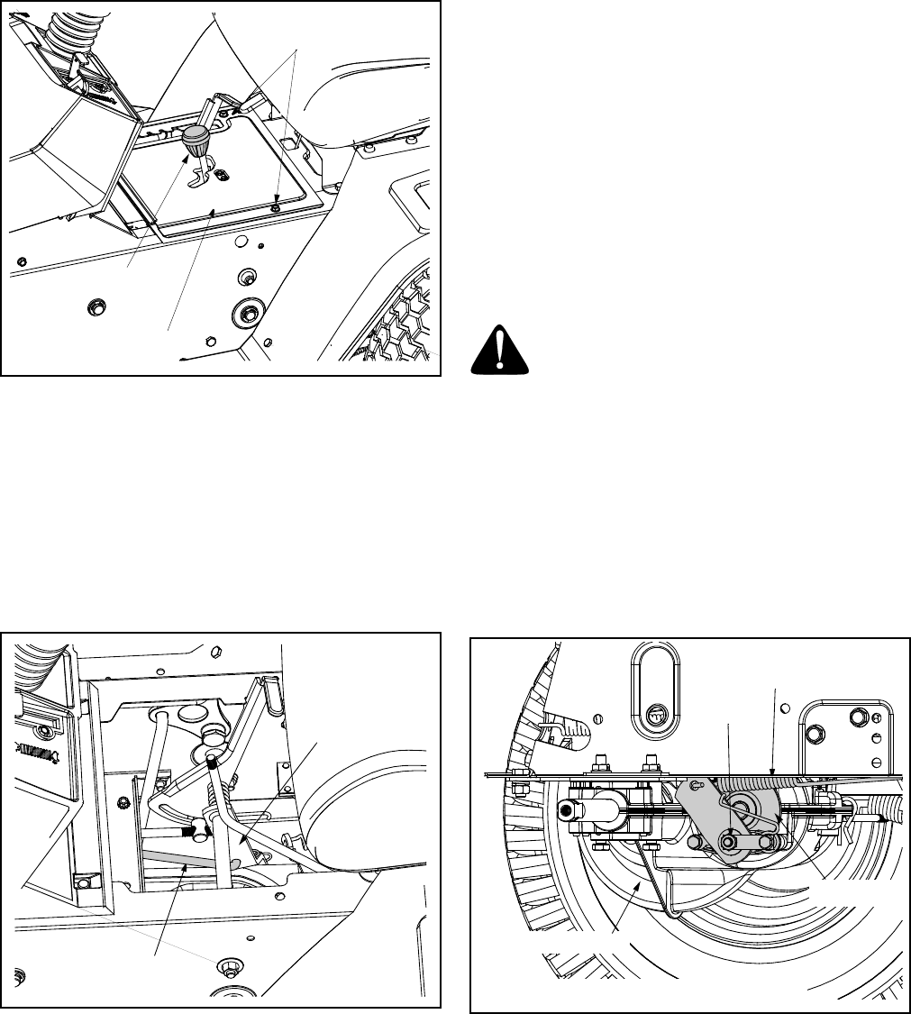
• With the engine off, place the deck engagement/lift
lever in the BLADES OFF position.
• Unthread the shift knob and remove the two flange
screws which secure the shift cover panel in place.
See Figure 7.
Figure 7
• Remove the shift cover panel and locate the deck
disengagement rod. See Figure 8.
NOTE: There is a small yellow wire connected to a
spring switch on the underside of the shift cover panel.
Be careful not to damage it when removing the panel.
• Remove the hairpin clip which secures the
disengagement rod to the stabilizer shaft assembly.
See Figure 8.
Figure 8
• Pull the rod toward the rear of the tractor (to take up
slack), then thread the rod inward or outward
(usually only one or two turns) until the rod lines up
as precisely as possible with the hole in the
stabilizer shaft.
NOTE: Threading the disengagement rod outward
(toward the rear of the tractor) provides for more belt
tension. Threading the disengagement rod inward
provides for less belt tension.
• Reinsert the ferrule and re-secure the rod with the
cotter pin removed earlier.
Check the adjustment by placing the deck engagement/
lift lever in the BLADES STOP position. The deck
should move up and forward, allowing the belt to
become loose.
• Reassemble the shift cover panel.
• Start the tractor’s engine and test the deck
engagement/lift lever to be certain the blades fully
disengage when in the BLADES STOP position.
• Repeat the adjustment procedure if necessary.
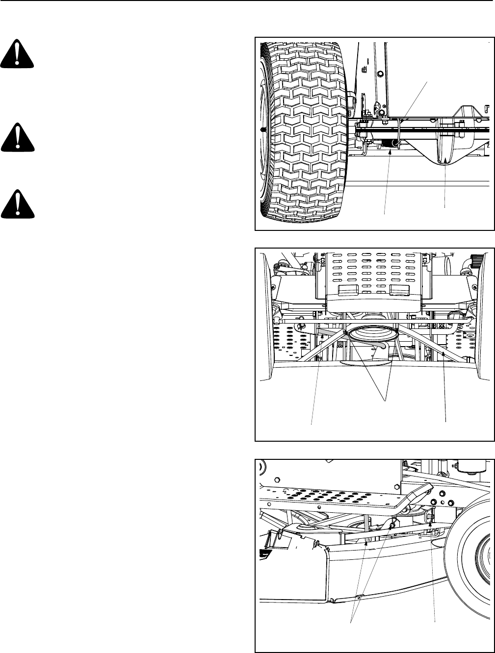
Parking Brake Adjustment
WARNING: Never attempt to adjust the
brakes while the engine is running. Always
disengage PTO, move shift lever into neutral
position, stop engine and remove key to
prevent unintended starting.
If the tractor does not come to a complete stop when
the clutch-brake pedal is completely depressed, or if
the tractor’s rear wheels can roll with the parking brake
applied, the brake is in need of adjustment. The brake
disc can be found on the right side of the transmission
in the rear of the tractor. Adjust if necessary as follows:
• Looking at the transmission from the right side of
the tractor, locate the compression spring and
brake disc. See Figure 9.
Figure 9
Shift Knob
Flange Screws
Shift Cover Panel
Disengagement Rod
Stabilizer Shaft
Assembly
Hex Nut
Compression
Spring
NOTE: Rear, right wheel not shown for clarity
Transmission
Brake Disc
16
• Loosen, but do NOT remove, the hex nut found on
the right side of the brake assembly. See Figure 9.
• Using a feeler gauge, set the gap between the
brake disc and the brake puck at .011".
• Re-tighten the hex nut loosened earlier.
Speed Control Adjustment
NOTE: When operating the unit initially or after
replacing the belts, there will be little difference
between the highest two speeds until after the belts
have gone through a break-in period and have seated
themselves into the pulleys.
If the full range of speeds cannot be obtained on your
lawn tractor, adjust the speed control as follows.
• Unthread the shift knob and remove the two flange
screws which secure the shift cover panel in place.
Refer to Figure 7.
• Remove the shift cover panel and locate the speed
control rod. See Figure 10.
Figure 10
NOTE: There is a small yellow wire connected to a
spring switch on the underside of the shift cover panel.
Be careful not to damage it when removing the panel
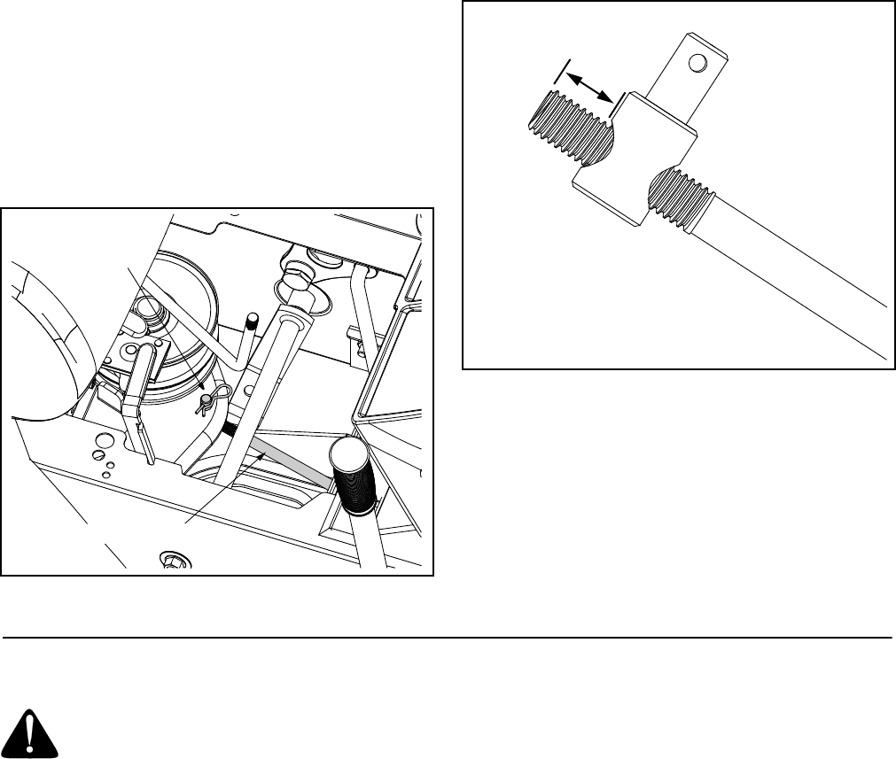
• Remove the hairpin clip which secures the speed
control rod’s ferrule to the speed bracket. See
Figure 10.
At the factory, the speed control rod is adjusted so that
5/8-in. of the rod is exposed beyond the ferrule.
• Adjust the speed control by threading the ferrule
inward so that no more than 3/4-in. of the rod is
exposed beyond the ferrule. See Figure 11.
Figure 11
• Reinsert the ferrule and re-secure the rod with the
cotter pin removed earlier.
• Reassemble the shift cover panel, start the tractor’s
engine and test the full range of speeds.
IMPORTANT:
If the above adjustment did not result in
the tractor obtaining the full range of speeds, see an
authorized MTD service dealer to have the variable
speed drive system inspected and professionally
adjusted.
SECTION 7: MAINTAINING YOUR LAWN TRACTOR
WARNING: Before performing any
maintenance or repairs, place the deck
engagement/lift lever in the BLADES STOP
position, move shift lever into neutral position,
set parking brake, stop engine and remove
key to prevent unintended starting.
Cleaning the Engine And Deck
Any fuel or oil spilled on the machine should be wiped
off promptly. Do NOT allow debris to accumulate
around the cooling fins of the engine or on any other
part of the machine, especially the belts, pulleys and
other moving parts. Clean the underside of the deck
with a wisk broom, scraper or forced air after each
mowing.
IMPORTANT:
The use of a pressure washer or garden
hose to clean your tractor is NOT recommended. It may
cause damage to electrical components, spindles,
pulleys, bearings or the engine. The use of water will
result in a shortened life of the tractor and reduce its
serviceability.
Speed Control Rod
Ferrule and
Hairpin Clip
3/4”
Maximum
NOTE: Figure is NOT to scale
17
Engine
Refer to the Briggs & Stratton Operator/Owner
Manual (or Tecumseh engine’s Owner’s Manual)
for engine maintenance instructions.
Check engine oil level before each use as instructed in
the Briggs & Stratton Operator/Owner Manual (or
Tecumseh engine’s Owner’s Manual) packed with your
unit. Follow the instructions carefully.
Changing Engine Oil
For draining oil from the engine’s crankcase of select
model tractors, a plastic oil drain sleeve is packed with
this Operator’s Manual. To drain the oil, proceed as
follows:
• Unscrew the oil fill cap and remove the dipstick
from the oil fill tube.
• Snap the small end of oil drain sleeve onto the oil
sump. See Figure 12.
Figure 12
• Remove drain plug and drain oil into a suitable
container with a capacity of no less than 64 oz.
• Service the oil filter (if so equipped) as instructed
in the separate Briggs & Stratton Operator/Owner
Manual (or Tecumseh engine’s Owner’s Manual)
packed with your unit.
Perform the above steps in the opposite order after oil
has finished draining.
• Refill the engine with new motor oil.
IMPORTANT:
Refer to the Briggs & Stratton Operator/
Owner Manual (or Tecumseh engine’s Owner’s
Manual) packed with your unit for information regarding
the quantity and proper weight of motor oil.
Air Cleaner
Service the pre-cleaner, if so equipped, and cartridge/
air cleaner element as instructed in the Briggs &
Stratton Operator/Owner Manual (or Tecumseh
engine’s Owner’s Manual) packed with your unit.
Fuel Filter
Service the fuel filter, if so equipped, as instructed in the
Briggs & Stratton Operator/Owner Manual (or
Tecumseh engine’s Owner’s Manual) packed with your
unit.
Spark Plug(s)
The spark plug(s) should be cleaned and the gap reset
once a season. Spark plug replacement is
recommended at the start of each mowing season.
Refer to the Briggs & Stratton Operator/Owner Manual
(or Tecumseh engine’s Owner’s Manual) for correct
plug type and gap specifications.
Lubrication
WARNING: Before lubricating, repairing, or
inspecting, always disengage PTO, move shift
lever into neutral position, set parking brake,
stop engine and remove key to prevent
unintended starting.
Engine
Lubricate the engine with motor oil as instructed in the
Briggs & Stratton Operator/Owner Manual (or
Tecumseh engine’s Owner’s Manual) packed with your
unit.
Wheels
The rear wheels should be removed from the axles
once a season. Lubricate the axles and the rims well
with an all-purpose grease before re-installing them.
Pivot Points & Linkage
Lubricate all the pivot points on the drive system,
clutch-brake pedal and lift linkage at least once a
season with light oil.
Steering Shaft and Gear
Lubricate teeth of steering gears with automotive multi-
purpose grease after every 25 hours of operation or
once a season. See Figure 13.
Figure 13
Oil Drain Sleeve
Oil Sump
Steering Shaft and Gear
18
SECTION 8: SERVICE
WARNING: Disconnect the spark plug wire
and ground against the engine before
performing any adjustments, repairs or
maintenance.
Cutting Deck Removal
WARNING: Shut the engine off, remove
ignition key, set the parking brake, disconnect
the spark plug wire(s) and ground against the
engine to prevent unintended starting before
removing the cutting deck.
WARNING: Always wear safety glasses or
safety goggles to protect your eyes while
removing the cutting deck.
For performing service on your tractor and in order to
properly mount some (separately available)
attachments, it may be necessary to remove the
tractor’s cutting deck. To due so, proceed as follows:
• Place the deck engagement/lift lever in the
engaged (all the way forward) position.
• Using a spring puller (Part No. 732-0571)or other
suitable tool, disconnect the spring which is
attached to a small hook found on the left, rear
portion of the transmission. See Figure 14.
• Place the deck engagement/lift lever in the
BLADES STOP position.
• Locate the two belt keeper pins, found on either
side of the engine pulley, and use a 1/4-inch socket
wrench to remove them from the lower frame. See
Figure 15.
NOTE: When reassembling, make certain belt keeper
pins are assembled in the same locations from which
they were removed.
• Unroute the deck belt from around the engine
pulley. Return the deck engagement/lift lever to the
engaged (all the way forward) position.
• Locate the deck anti-sway rod and front deck links
found near the front of the cutting deck. See Figure
15 & Figure 16.
• First remove the hairpin clip which secures the anti-
sway rod to the front portion of the cutting deck,
then remove the hairpin clips which secure the
front deck links. Retain the hairpin clips.
• Carefully lower the front portion of the deck to the
ground.
Figure 14
Figure 15
Figure 16
Spring
Hook
Transmission
Belt Keeper Pins
Deck Anti-sway Rod Deck Belt
Deck Anti-sway Rod
Front Deck Links and Hairpin Clip
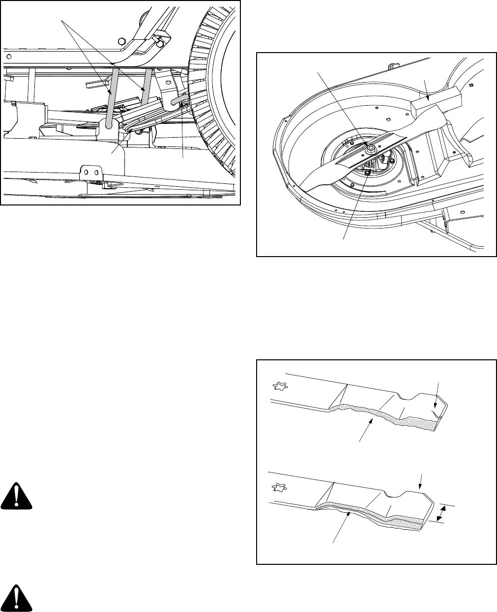
19
• Remove the hairpin clips which secure the rear
deck hangers to the deck stabilizer bracket. See
Figure 17. Retain the hairpin clips.
Figure 17
NOTE: The style and shape the stablizer bracket and
stablizer rod vary. Yours may differ slightly from that
shown in Figure 17.
• Carefully lower the rear portion of the deck to the
ground.
NOTE: For normal service and maintenance, the
deck stabilizer bracket doesn’t need to be removed
from the tractor. If removing the cutting deck in order to
mount a Snow Thrower attachment, however, the
stabilizer bracket must be removed. To do so, simply
remove the hairpin clip which secures the stabilizer rod
to the stabilizer bracket. See Figure 17.
• Place the deck engagement/lift lever in the
BLADES STOP position to raise the lift links up,
and out of the way.
• Carefully slide the deck from beneath the right side
of the lawn tractor.
Cutting Blades
WARNING: Be sure to shut the engine off,
remove ignition key, disconnect the spark plug
wire(s) and ground against the engine to
prevent unintended starting before removing
the cutting blade(s) for sharpening or
replacement. Protect your hands by using
heavy gloves or a rag to grasp the cutting
blade.
WARNING: Periodically inspect the blade
adapter and/or spindle for cracks or damage,
especially if you strike a foreign object.
Replace immediately if damaged.
The blades may be removed as follows.
• Remove the deck from beneath the tractor, (refer to
Cutting Deck Removal on page 18) then gently flip the
deck over to expose its underside.
• Place a block of wood between the center deck
housing baffle and the cutting blade to act as a
stabilizer. See Figure 18.
Figure 18
• Use a 15/16" wrench to remove the hex flange nut
that secures the blade to the spindle assembly. See
Figure 18.
To properly sharpen the cutting blades, remove equal
amounts of metal from both ends of the blades along
the cutting edges, parallel to the trailing edge, at a 25°
to 30° angle. See Figure 19.
Figure 19
IMPORTANT:
If the cutting edge of the blade has already
been sharpened to within 5/8" of the wind wing radius,
or if any metal separation is present, replace the blades
with new ones. See Figure 19.
Rear Deck Hangers
Stabilizer Rod
Stabilizer Bracket
Spindle Assembly
Hex Flange Nut Wood Block
Blade Separation
Worn Blade Edge
Wind Wing
Sharpen Edge Evenly
5/8"
minimum

20
It is important that each cutting blade edge be ground
equally to maintain proper blade balance. A poorly
balanced blade will cause excessive vibration and may
cause damage to the tractor and result in personal
injury.
The blade can be tested by balancing it on a round
shaft screwdriver. Grind metal from the heavy side until
it balances evenly.
When replacing the blade, be sure to install the blade
with the side of the blade marked ‘‘Bottom’’ (or with a
part number stamped in it) facing the ground when the
mower is in the operating position.
IMPORTANT:
Use a torque wrench to tighten the blade
spindle hex flange nut to between 70 foot-pounds and
90 foot-pounds.
Battery
The battery is sealed and is maintenance-free. Acid
levels cannot be checked.
• Always keep the battery cables and terminals clean
and free of corrosive build-up.
• After cleaning the battery and terminals, apply a
light coat of petroleum jelly or grease to both
terminals
• Always keep the rubber boot positioned over the
positive terminal to prevent shorting.
IMPORTANT:
If removing the battery for any reason,
disconnect the NEGATIVE (Black) wire from it’s
terminal first, followed by the POSITIVE (Red) wire.
When re-installing the battery, always connect the
POSITIVE (Red) wire its terminal first, followed by the
NEGATIVE (Black) wire. Be certain that the wires are
connected to the correct terminals; reversing them
could change the polarity and cause damage to your
engine’s alternating system.
Charging
If the tractor has not been put into use for an extended
period of time, charge the battery with an automotive-
type 12-volt charger for a minimum of one hour at six
amps.
WARNING: Batteries give off an explosive
gas while charging. Charge battery in a well
ventilated area and keep away from an open
flame or pilot light as on a water heater, space
heater, furnace, clothes dryer or other gas
appliances.
Jump Starting
WARNING: When removing or installing
the battery, follow these instructions to
prevent the screwdriver from shorting against
the frame.
IMPORTANT:
Never jump your tractor’s dead battery
with the battery of a running vehicle.
• Connect end of one jumper cable to the positive
terminal of the good battery, then the other end to
the positive terminal of the dead battery.
• Connect the other jumper cable to the negative
terminal of the good battery, then to the frame of
the unit with the dead battery.
WARNING: Failure to use this procedure
could cause sparking, and the gas in either
battery could explode.
Cleaning
Clean the battery by removing it from the tractor and
washing with a baking soda and water solution. If
necessary, scrape the battery terminals with a wire
brush to remove deposits. Coat terminals and exposed
wiring with grease or petroleum jelly to prevent
corrosion.
Battery Failures
Some common causes for battery failure are:
• incorrect initial activation • undercharging
• overcharging • corroded connections
• freezing
These failures are NOT covered by your tractor’s
warranty.
Tires
Recommended operating tire pressure is
approximately 10 p.s.i. Maximum tire pressure under
any circumstances is 30 p.s.i. Equal tire pressure
should be maintained on all tires.
When installing a tire to the rim, be certain rim is clean
and free of rust. Lubricate both the tire and rim
generously. Never inflate to over 30 p.s.i. to seat
beads.
WARNING: Excessive pressure (over 30
p.s.i.) when seating beads may cause tire/rim
assembly to burst with force sufficient to
cause serious injury.
Belt Replacement
WARNING: Shut the engine off, remove
ignition key, set the parking brake, disconnect
the spark plug wire(s) and ground against the
engine to prevent unintended starting before
replacing belts.
For performing service on your tractor and in order to
properly mount some (separately available)
attachments, it may be necessary to remove the
tractor’s cutting deck. To due so, proceed as follows:
21
Deck Belt
WARNING: Shut the engine off, remove
ignition key, set the parking brake, disconnect
the spark plug wire(s) and ground against the
engine to prevent unintended starting before
removing the cutting deck.
WARNING: Always wear safety glasses or
safety goggles to protect your eyes while
removing the cutting deck.
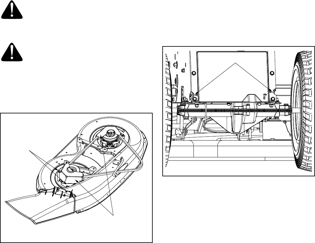
• Remove the cutting deck from the tractor (Refer to
Cutting Deck Removal on page 18, for detailed
instructions).
• Remove the belt guards (located over each spindle
pulley) by removing the self-tapping screws which
secure them in place. See Figure 20.
Figure 20
• Remove and replace the belt, reassemble following
the instructions in reverse order.
Drive Belts (Upper and Lower)
NOTE: The engine pulley must be removed from the
engine’s crankshaft in order to change the tractor’s
drive belts. Doing so requires an air/impact wrench.
It is recommended that both belts be changed at the
same.
• Place the deck engagement/lift lever in the
engaged (all the way forward) position.
• Unthread the shift knob and remove the two flange
screws which secure the shift cover panel in place.
Refer to Figure 7. Remove the shift cover panel.
NOTE: There is a small yellow wire connected to a
spring switch on the underside of the shift cover panel.
Be careful not to damage it when removing the panel.
• Using a spring puller (Part No. 732-0571)or other
suitable tool, disconnect the spring which is
attached to a small hook found on the left, rear
portion of the transmission. Refer to Figure 14.
• Using a spring puller (Part No. 732-0571)or other
suitable tool, disconnect the two springs which are
attached to the rear portion of the tractor frame.
See Figure 21.
Figure 21
• Place the deck engagement/lift lever in the
BLADES STOP position.
• Locate the two belt keeper pins, found on either
side of the engine pulley, and use a 1/4-inch socket
wrench to remove them from the lower frame. Refer
to Figure 15.
NOTE: When reassembling, make certain belt keeper
pins are assembled in the same locations from which
they were removed.
• Using an impact gun with a 5/8-inch socket, remove
the hex screw with secures the engine pulley to the
engine crankshaft.
• Carefully lower the pulley off of the crankshaft and
remove the belt from around it.
• Disconnect the battery cables from the terminals
(disconnect the NEGATIVE (Black) wire from it’s
terminal first, followed by the POSITIVE (Red)
wire).
• Detach the battery hold-down rod and remove both
the battery and battery tray from the tractor.
• Locate the transmission pulley though the battery
tray opening. See Figure 22.
• Using an impact gun with a 13/16-inch socket,
remove the pulley from the transmission’s input
shaft by removing the flange nut which secures it
• Carefully lift the pulley off of the transmission’s
input shaft and remove the upper drive belt from
around it and the variable speed.
Self-Tapping
Screws
Belt Guards
Springs
22
Figure 22
NOTE: A spacer is located beneath the transmission
pulley. Be careful not to lose the spacer and be certain
NOT reinstall the spacer upside down.
• Remove the lower drive belt from around the lower
portion of the variable speed pulley and feed it
toward the shift cover panel opening.
• Remove the lower drive belt by lifting it through the
cover panel opening
• Reassemble new belts, following the previous
instructions in reverse order.
IMPORTANT:
When remounting the engine pulley,
torque the hex bolt to between 38 foot-pounds and 50
foot-pounds.
IMPORTANT:
When remounting the transmission pulley,
torque the flange nut to between 25 foot-pounds and 33
foot-pounds.
SECTION 9: OFF-SEASON STORAGE
WARNING: Never store the machine or
fuel container indoors where there is an
open flame, spark or pilot light such as on
water heater, furnace, clothes dryer or other
gas appliance.
WARNING: Use a fuel stabilizer additive
or drain the fuel into an approved container
outdoors, away from an open flame. Allow
engine to cool. Extinguish cigarettes, cigars,
pipes, and other sources of ignition prior to
draining fuel. Fuel left in engine without a
stabilizer additive for extended periods
deteriorates and will cause problems.
If the machine is to be inoperative for a period longer
than 30 days, prepare for storage as follows.
• Clean the engine and the entire unit thoroughly.
• We do not recommend the use of pressure
washers or garden hose to clean your unit. They
may cause damage to electric components,
spindles, pulleys, bearings or the engine. The use
of water will result in shortened life and reduce
serviceability.
• Lubricate all lubrication points. Wipe the entire
machine with an oiled rag to protect the surfaces.
• Refer to the engine manual for correct engine
storage instructions. The engine must be
completely drained of fuel to prevent gum deposits
from forming on essential carburetor parts, fuel
lines and fuel tanks.
Charge battery fully. The battery loses some of its
charge each day when the unit is not used.
NEVER store battery without a full charge. Recharge
battery before returning to service or every two months,
whichever occurs first.
• When storing unit for extended periods, disconnect
battery cables. Removing battery from unit is
recommended.
• Store unit in a clean, dry area. Do not store next to
corrosive materials, such as fertilizer.
NOTE: When storing any type of power equipment in
an unventilated or metal storage shed, care should be
taken to rustproof the equipment. Using a light oil or
silicone, coat the equipment, especially any chains,
springs, bearings and cables.
Transmission Pulley
Flange Nut

23
SECTION 10: ATTACHMENTS & ACCESSORIES
The following attachments and accessories are compatible for Lawn Tractor Models 650 & 652. See the retailer
from which you purchased your tractor, an authorized MTD Service Dealer or phone (800) 800-7310 for information
regarding price and availability. Lawn tractor models 650 & 652 are NOT designed for use with any type of ground-
engaging attachments (e.g. tiller or plow). Use of this type of equipment WILL void the tractor’s warranty.
SECTION 11: TROUBLE SHOOTING GUIDE
MODEL DESCRIPTION
OEM-190-116 38- and 42-inch Deck Mulch Kit
OEM-190-180 Twin Bagger Grass Collector (for 38- and 42-inch Decks)
OEM-190-215 Rear Wheel Weights (Two per set)
OEM-190-226 Front Bumper Kit
OEM-190-620 46-inch Front Dozer Blade
OEM-190-627 42-inch Two-stage Snow Thrower
OEM-190-664 Tire Chains, for 18” x 6.5” tires (Two per set)
OEM-190-808 Deluxe Tractor Sunshade
Trouble Possible Cause(s) Corrective Action
Engine will not
crank Safety switch button
not depressed.
Battery installed
incorrectly.
Battery is dead or
weak.
Blown fuse or circuit
breaker.
Engine ground wire
loose.
There are two switches in the starting circuit of your unit: the clutch pedal switch and
the deck engagement/lift lever switch. Make certain the actuator is fully depressing
the buttons on each switch.
The battery must be installed with negative terminal attached to black ground wire.
Negative terminal is identified at the post by “NEG”, “N” or “-”. The positive terminal,
identified by “POS”, “P” or “+”, must be attached to the big red wire which goes to the
solenoid. All batteries are to be fully charged before installing.
Charge with 6 AMP charger until fully charged.
Refer to schematic for fuse location and replace fuse if blown. If fuse blows repeat-
edly, see an authorized service dealer to have the tractor’s wire harness serviced.
Engine should have a black ground wire running from engine to frame or mounting
bolt.
Engine cranks
but will not start Throttle not in cor-
rect position.
No fuel to the carbu-
retor.
No spark to spark
plug.
Dirty air cleaner.
Refer to Starting the Engine in this manual for correct position of the throttle control.
Gasoline tank empty. Fill with clean, fresh gasoline.
Fuel line or in-line fuel filter plugged. Remove and clean fuel line. Replace filter if
necessary.
Spark plug lead disconnected. Connect lead.
Faulty spark plug. Replace spark plug.
Refer to the engine manual packed with your unit. If the air cleaner is dirty, replace it
Engine smokes Engine oil has been
overfilled.
Engine loses crank-
case vacuum.
Check oil level. Drain as necessary.
Dipstick not seated or broken. Replace dipstick.
Engine breather defective. Replace.
Excessive
vibration Bent or
damaged blade.
Bent blade.
Stop engine immediately. Check all pulleys, blade adapters, keys and bolts for
tightness and spindle damage. Tighten or replace any damaged parts.
Stop engine immediately. Replace damaged blade. Only use original equipment
blades.
Mower will not
discharge grass
or leaves uncut
strips
Engine speed low.
Speed selection.
Cutting height set too
low.
Blades short or dull.
Always operate the cutting deck with throttle control set in the FAST (rabbit) position.
Slow your ground speed. The slower your ground speed, the better the quality of cut.
Raise deck.
Sharpen or replace blades (uncut strip problem only).
24
B
12
10 15†
A
A
8
17
18
6
7
933
11
13†
4
16
2
32
31
30
23
27
3
23
28
† Found on Model 652 Only
22
25
29
24
26
34
B
19
7
33
21†
36†
37†
1†
35†
34
14†B
4
20†
38
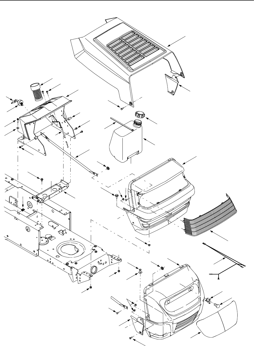
SECTION 12: MODELS 650 & 652 PARTS LIST

25
Models 650 & 652
REF.
NO. PART
NO. DESCRIPTION
1 710-3008 Hex Screw, 5/16-18 x .75
2 710-0642 Self-tapping Screw, 1/4-20 x .75
3 712-0185 U-type Speed Nut, 1/4-20
4 712-0429 Hex Lock Nut, Nylon, 5/16-18
5 712-3027 Flange Lock Nut, 1/4-20
6 726-0201 Speed Nut, .3125
7 726-04012 Push-on Nut, .25
8 731-1601 Lens, Black
9 738-04015 Shoulder Screw, 5/16-18 x .625
10 738-0952A Shoulder Screw, 1/4-20 x .375 /.125
11 749-0722C Grille Support Rod
12 783-0250A Hood w/ Louvers
13 629-0469B Headlamp Harness Assembly
14 783-0366 RH Side Panel (Insert)
15 783-0367 LH Side Panel (Insert)
16 731-04612 Grille
17 725-1396 Ignition Switch, 6-pin
18 725-0201 Keys (pair)
19 710-0751 Hex Screw, 1/4-20 x .620
20 725-0963 Headlamp, 12V
21 725-1651 Headlamp Socket
22 17632D Support Bracket
23 710-0599 Self-tapping Screw, 1/4-20 x .5
24 710-0607 Self-tapping Screw, 5/16-18 x .5
25 710-0788 Self-tapping Screw, 1/4-20 x 1.0
26 726-3054 U-type Speed Nut, 1/4-20
27 731-04179 Dash Panel
28 746-04020A Throttle / Choke Control, 18.5”
29 736-3090 Flat Washer, .260 x .720 x .060
30 726-0209 Cable Tie, 30.66
31 751-0555B Fuel Tank, 1.5 gal.
32 751-0603 Fuel Tank Cap
33 728-0162 Rivet, 1/4”
34 712-0324 Hex Lock Nut, Nylon, 1/4-20
35 736-3078 Flat Washer, .344 x 1.0 x .063
36 731-1503A Lens
37 783-0156B Grille
38 731-04387 Steering Bellow
NOTE: Tractor features vary by model. NOT all parts listed above and pictured on the previous page are standard equipment.
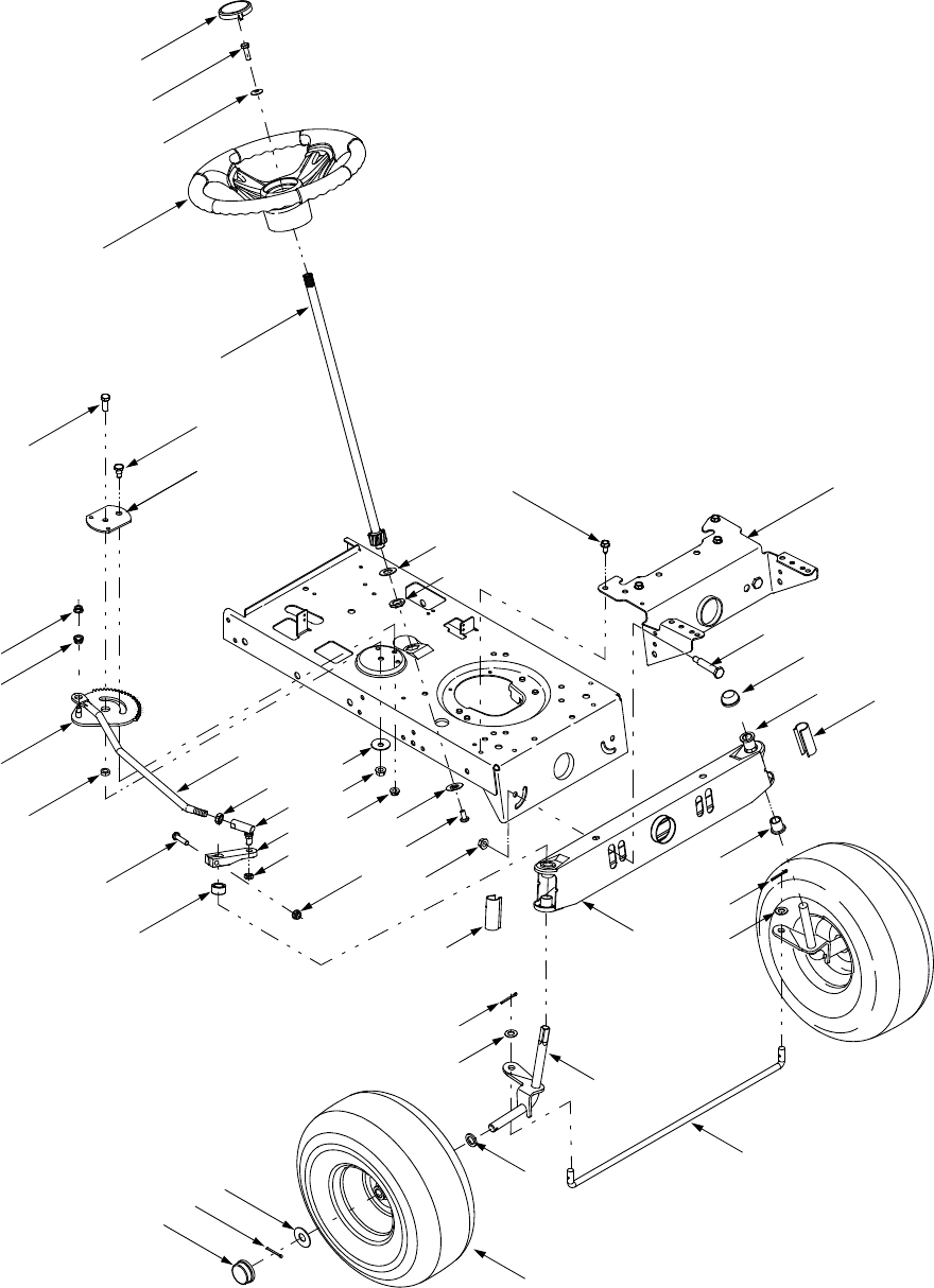
26
2
37
40
15
21
4
19
35
24
3
22
1
11
25
13
17
27
20
11
33
29
6
10
814
9
31
11
32
30
7
10
534
28
12
16
26
38
12
18 39
36
12
18
40
23
37
Models 650 & 652

27
Models 650 & 652
REF.
NO. PART
NO. DESCRIPTION
1 17198A Retainer Gear Segment Plate
2 683-0002A Steel Pivot Bar, .625
3 710-0514 Hex Cap Screw, 3/8-16 x 1.0
4 710-0643 Hex Cap Screw, 5/16-18 x 1.0
5 710-0726 Self-tapping Screw, 5/16-12 x .75
6 710-0805 Hex Cap Screw, 5/16-18 x 1.5
7 710-1309 Machine Screw, 5/16-18 x .75
8 712-0240 Jam Nut, 7/16-20 (Grade 2)
9 712-0262 Jam Nut, 3/8-24
10 712-0431 Flange Lock Nut, 3/8-16
11 712-3004A Flange Lock Nut, 5/16-18
12 714-0470 Cotter Pin, 1/8 x 1.25
13 717-1757A Stearing Segment Gear
14 723-0448A Ball Joint, 7/16 -20
15 726-0214 Push Cap, .625
16 731-0484A Hub Cap
17 736-0187 Flat Washer, .64 x 1.24 x .060
18 736-0226 Flat Washer, .474 x .879 x .064
19 736-0242 Bell Washer, .34 x .872 x .060
20 736-0356 Bell Washer, .391 x .380 x .062
21 731-04039 Steering Wheel Cap, Small
731-04040 Steering Wheel Cap, Small, w/ Sprig
22 738-0141 Shoulder Screw, .435 x .350, 5/16-18
23 738-0527 Shoulder Screw, .498 x 2.045
24 738-0919 Steering Shaft, 21.86
25 741-0475 Plastic Bushing, .38 ID
26 736-0162 Flat Washer, .64 x 1.0 x .12
27 741-0656 Hex Flange Bearing, 5/8
28 736-0285 Flat Washer, .635 x 1.589 x .06
29 747-1268B Steering Drag Link, 7/16-20
30 748-0389 Cap, 1.25 x .16
31 748-04014B Steering Arm
32 748-04020 Spacer, 1.0 x .645 x .56
33 750-0535 Spacer, .380 x .625 x .21
34 783-0041D Pivot Bar Bracket
35 631-04028 Steering Wheel, Three Spoke
36 747-04057 Tie Rod
37 731-04057A Axle End Cap, Standard
38 634-0097B Wheel Ass’y Complete
39 683-04014 RH Axle Assembly
683-04013 LH Axle Assembly
40 741-0487A Flange Bearing
NOTE: Tractor features vary by model. NOT all parts listed above and pictured on the previous page are standard equipment.
Wheel Ass’y
Complete Rim Assembly Inner Bearing Outer Bearing Tire Only Air Valve
634-0097B 634-0171B 741-0706
(Flange w/ Fitting)
741-0487A
(Plastic Flange)
734-0298
(13 x 5 x 6)
734-0255
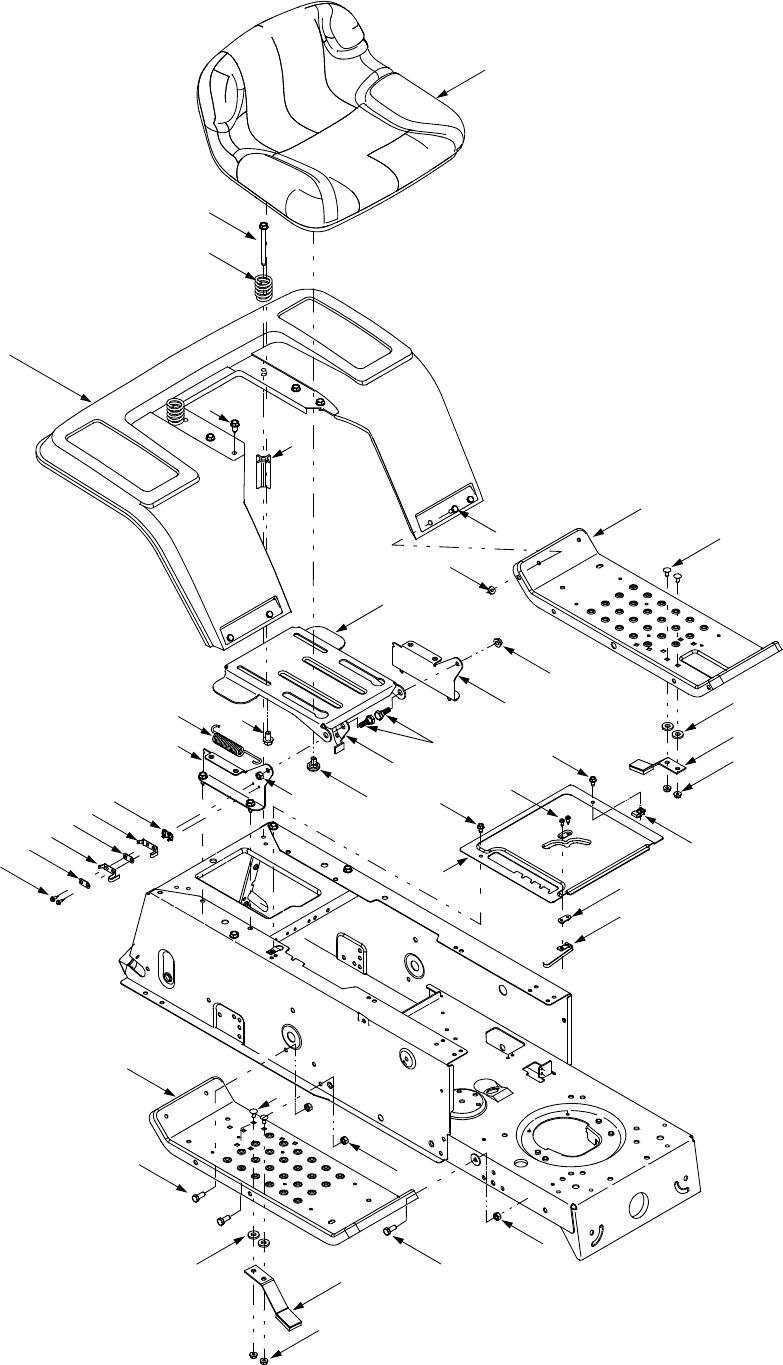
28
14
6
3
12
1
30
11*
2
6
9
8
10
7
10
4
16
20
5
21
13
31
17
17 18
32
18
19
32
19
18
31
22
15
23 4
23
26
25
24
27
29
* Attach the short end of spring to the notch in the rear
of Ref. No. 2. Attach the long end to Ref. No. 1.
33
34
Models 650 & 652
35
35

29
Models 650 & 652
REF.
NO. PART
NO. DESCRIPTION
1 17239C Seat Lift Bracket
2 17950A RH Pivot Support Bracket, Seat
3 17951A LH Pivot Support Bracket, Seat
4 710-0227 Self-tapping Screw, #8-18 x .50
5 710-0726 Self-tapping Screw, 5/16-12 x .75
6 712-0429 Hex Lock Nut, 5/16-18
7 725-1303 Outer Seat Spring Switch
8 725-1439 Inner Seat Spring Switch
9 726-0278 Insulator Plate Boss
10 726-0279 Insulator Plate
11 732-0581B Extension Spring, .75 x 5.31
12 738-0296 Shoulder Screw, .437 x .286
13 17770H Running Board
14 17870C Fender
15 710-0751 Hex Screw, 1/4-20 x .620
16 710-1208 Self-tapping Screw, 5/16-18 x 3.5
17 710-3008 Hex Screw, 5/16-18 x .75
18 712-0429 Nylon Lock Nut, 5/16-18
19 712-3027 Flange Lock Nut, 1/4-20
20 732-04038 Compression Spring, 1.314 x 1.8
21 750-04212 Spacer
22 783-04139A LH Running Board
23 710-0599 Self-tapping Screw, 1/4-20 x .5
24 725-1643 Spring Switch, Long
25 726-0320 Insulator Nut Plate
26 726-3054 U-Clip Nut, 1/4-20
27 783-04429 Shift Cover Panel, 5-speed
28 710-0870 Screw, 3/8-16 x .625
29 738-04012 Shoulder Screw, .625 x .175, 3/8-16
30 783-04081A Seat Pivot Bracket, Manual Adjust
31 710-0703 Carriage Screw, 1/4-20 x .75
32 761-0168B Blade Spindle Brake Assembly
33 757-04021 Low Back Seat, Black
34 710-0870 Screw, 3/8-16 x .625
35 736-3008 Flat Washer, .344 x .750 x .120
NOTE: Tractor features vary by model. NOT all parts listed above and pictured on the previous page are standard equipment.
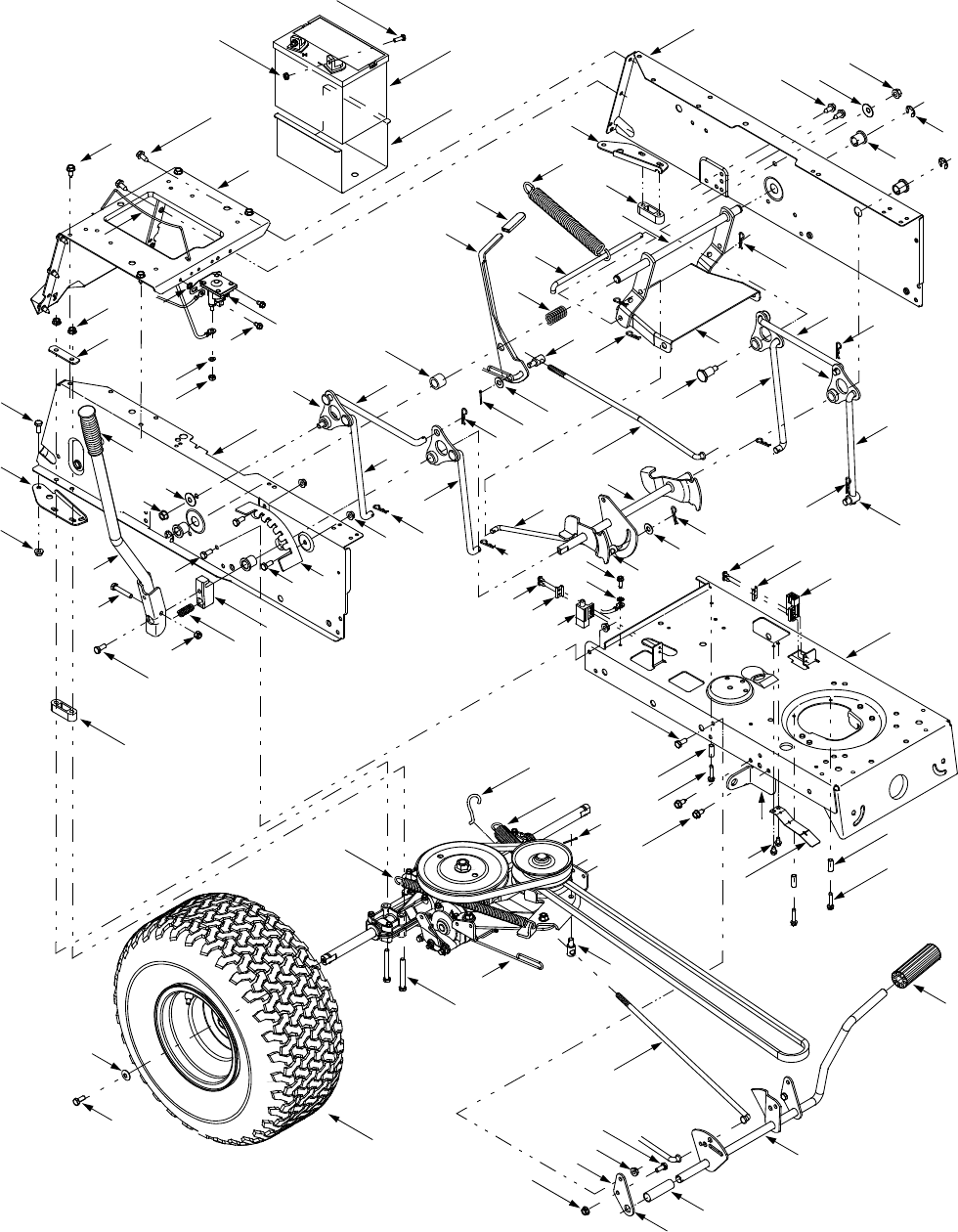
30
62
55 69
33
68
57
71
35
67
12
13 4913
12
66
64
65
63
52
33
56
51
58*
43
63
52
10
70
10
13
48
37 34
15
21
45
35
31
36
2
35
39 40
40 35
44
42
32
35
38
5
41
35
35
40
44
40
40
13 6330
9
19
6330
12
1
13
59*
29
7
18
8
13 17
11
12
4
16
46
12
34 37
20
14
33
10
10
25
50
7
19
28
27
26
22
24
72
53
54
61
8
74
35
60
23
B
A
C
A
B
C
D
D
55
* Attach the ends of springs (Ref. 58 & Ref.59)
to the notch openings in the rear of Ref. 25.
E
†
†
Refer to
E
†
on Page 36
Models 650 & 652
75
75

31
Models 650 & 652
REF.
NO. PART
NO. DESCRIPTION
1 17668A RH Axle Support Bracket
2 17669A LH Axle Support Bracket
3 17962 Switch Plate
4 683-04025 Lift Handle Assembly
5 683-04049 Lift Shaft Assembly
6 710-0224 Self-tapping Screw, #10-16 x .5
7 710-0599 Self-tapping Screw, 1/4-20 x .5
8 710-0627 Hex Cap Screw, 5/16-24 x .75
9 710-0642 Self-tapping Screw, 1/4-20 x .75
10 710-0726 Self-tapping Screw, 5/16-12 x .75
11 710-3180 Hex Cap Screw, 5/16-18 x 1.75
12 710-3008 Hex Screw, 5/16-18 x .75
13 712-0429 Hex Lock Nut, 5/16-18
14 712-3006 Hex Nut, 1/4-20
15 716-0106 E-Ring, .625 Dia Shaft
16 720-0233 Handle Grip
17 732-0369 Compression Spring, .55 x 1.37
18 732-0750A Switch Actuator Spring
19 736-0222 External Lock Washer, 1/4
20 736-0329 Lock Washer, 1/4
21 741-0487A Flange Bearing, .632 ID
22 747-04031 Battery Hold-down Rod
23 748-04011A Lift Shaft Connector
24 783-0345 Battery Tray
25 783-0355D Hitch Plate
26 783-04011A Lower Frame
27 783-04031 LH Upper Frame Side Panel
28 783-04032 RH Upper Frame Side Panel
29 783-04213 Deck Anti-sway Bracket
30 725-04039 Screw-mount Interlock Switch
31 683-04048 Stabilizer Shaft Assembly
32 711-04036 Ferrule, 1/2-20 x .50
33 711-04075A Ferrule, 3/8-24 x .375
34 712-0130 Hex Lock Nut, 3/8-16
35 714-04023 Internal Cotter Pin, .080 x 1.56
36 732-04050A Extension Spring, 1.07 x 9.52
37 736-0219 Bell Washer, .389 x 1.12 x .030
38 736-0267 Flat Washer, .385 x .87 x .060
39 738-0322 Shoulder Bolt, .625 x .217
40 747-04018A Deck Hanger Link
41 747-04040A Deck Disengagement Rod
42 747-04069A Deck Hanger Link
43 747-04157 Rear Stabilizer Rod
44 748-04307 Lift Link
45 783-04294 Deck Stabilizer Bracket
46 783-04113 Deck Lift Index Bracket
47 17630A Shift Lever Retainer
48 17840 Transaxle Mounting Bracket
49 17860 Pedal Mounting Bracket
50 725-1426 Solenoid
51 710-0176 Hex Cap Screw, 5/16-18 x 2.75
52 710-0809 Self-tapping Screw, 1/4-20 x 1.25
53 712-0271 Hex Sems Nut, 1/4-20
54 710-3015 Hex Screw,1/4-20 x .75
55 714-0470 Cotter Pin
56 732-04029 Extension Spring, .59 x 12.38
57 783-04059 Speed Select Lever
58 732-04075A Extension Spring, .73 x 12.54
59 732-04076 Extension Spring, 1.15 x 7.90
60 732-0722A Brake Return Spring
61 736-0242 Bell Washer, .34 x .872 x .060
62 747-04043 Variable Speed Control Rod
63 750-0566A Spacer, .260 x .372 x 1.030
64 683-04005A Clutch / Brake Pedal Assembly
65 735-0196 Foot Pad, 4.6
66 750-0802 Spacer, .640 x .76 x 2.63
67 720-04008 Shift Handle Grip
68 732-04017 Compression Spring, .89 x 1.75
69 736-0300 Flat Washer, .406 x .875 x .059
70 747-04039 Speed Control Rod
71 750-04080 Spacer, .640 x 1.0 x .78
72 725-1737A Battery, 190 CCA
73 712-3027 Flange Lock Nut, 1/4-20
74 734-0592 Wheel Ass’y Complete
75 749-0334 Spacer
REF.
NO. PART
NO. DESCRIPTION
NOTE: Tractor features vary by model. NOT all parts listed above and pictured on the previous page are standard equipment.
Wheel Assembly
Complete Rim Assembly Tire Only Air Valve
734-0592 634-0069 734-0294
(18 x 6.5 x 8) 734-0255
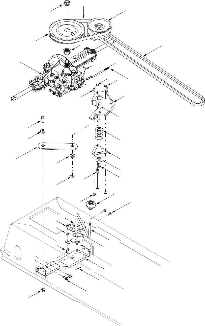
32
27
18
29
31
26
32
28
30
12
24
23
2
16
25
1
A
B
BA
14
21
7
10 4
6
20
15
17
8
13
22
6
19
519
11
10
9
11
3
33
Models 650 & 652

33
Models 650 & 652
REF.
NO. PART
NO. DESCRIPTION
1 618-04034 Transmission, Single-speed
2 656-0059A Variable-speed Pulley, 4.75
3 683-04055 Torque Bracket
4 683-04056 Variable-speed Bracket
5 683-04057 Variable-speed Bracket
6 710-0514 Hex Cap Screw, 3/8-16 x 1.0
7 710-0606 Hex Cap Screw, 1/4-20 x 1.5
8 710-0627 Hex Cap Screw, 5/16-24 x .75
9 710-1260A Screw, 5/16-18 x .75
10 710-3015 Hex Screw,1/4-20 x .75
11 712-0431 Flange Lock Nut, 3/8-16
12 712-0700 Flange Nut, 9/16-18
13 712-3027 Flange Lock Nut, 1/4-20
14 714-0209 Internal Cotter Pin, .125
15 718-04012 Bearing Cup
16 718-0758A Pulley Hub, 5/8 Spline
17 736-0362 Flat Washer, .320 x 1.25 x .06
18 720-04028 Shift Knob
19 738-0372B Shoulder Spacer, 1.0 x .38 x .38
20 741-0600 Ball Bearing, 17 x 40 x 12
21 747-04072 Shift Rod
22 750-04099 Stepped Spacer
23 754-04001A Lower Drive Belt
24 754-04002 Upper Drive Belt
25 756-04002 Transmission Pulley, 7.25
26 710-0599 Self-tapping Screw, 1/4-20 x .5
27 647-04019 Shift Lever Assembly
28 711-0736 Ferrule, 1/4-20 x 1.0
29 714-0104 Cotter Pin, 1.13
30 714-0470 Cotter Pin, 1.25
31 732-04067 Spring Compression Clip
32 736-0275 Flat Washer, .344 x .688 x .065
33 17630A Shift Lever Retainer
NOTE: Tractor features vary by model. NOT all parts listed above and pictured on the previous page are standard equipment.
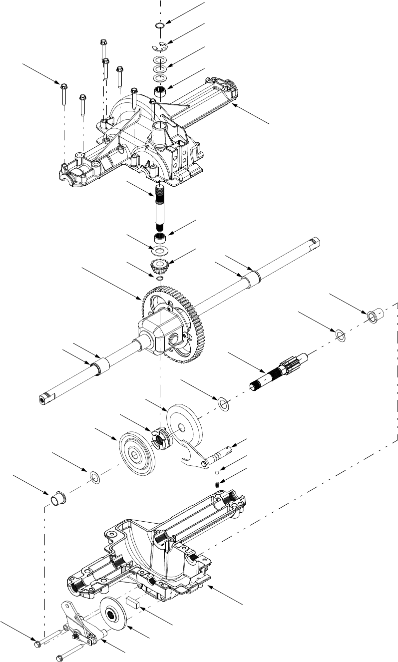
34
Models 650 & 652
8
3
2
1
5
6
8
4
10
9
7
1211
1112
13
14
3
17
15
16
18
19
20
21
22
23
24
25
28
29
27
26

35
Models 650 & 652
NOTE: If rebuilding the upper housing, include two ounces (2 oz.) of Unirex® N3 grease (Part No. 737-0289) in the input shaft cavity.
REF.
NO. PART
NO. DESCRIPTION
1 732-0614 Ring, Wire
2 716-0231 Ring, E Type, .750
3 736-0336 Flat Washer, 5/8 x 1.0 x .030*
736-0337 Flat Washer, 5/8 x 1.0 x .040*
736-0349 Flat Washer, 5/8 x 1.0 x .020*
4 736-0335 Washer, Thrust .635 x 1.26 x .06
5 710-1325 Self-tapping Screw, 1/4-20 x 1.625
6 719-04017 Upper Housing
7 711-1109 Input Shaft
8 741-0335 Needle Bearing, .625 x .813 x .495
9 717-1464 14-tooth Bevel Pinion
10 716-0108 Retaining Ring, .437
11 741-0340 Sleeve Bearing, .75 x .1.0 x 1.0
12 721-0338 Seal, .75 x 1.0 x .125
13 618-04041 Differential Assembly
14 741-0336 Flange Bearing, 5/8 x 3/4 x 3/4
15 717-1362 42-tooth Bevel Gear
16 717-1363 42-tooth Bevel Gear
17 718-0228 Clutch Collar
18 736-0519 Flat Washer, .70 x 1.125 x .031
19 711-04053 Drive Shaft
20 736-0495 Thrust Washer, 1.0 x .632 x .0
21 741-0337 Flange Bearing, 5/8 x 3/4 x 15/16
22 611-0011 Detent Shaft Assembly
23 741-0862 Detent Ball
24 732-0863 Compression Spring
25 719-04018 Lower Housing
26 717-0678 Brake Puck
27 761-0202 Brake Disc
28 710-1206 Self-tapping Screw, 1/4-20 x 2.375
29 661-0001 Brake Assembly
— 737-0148 Grease (19 oz.)
*Use applicable flat washer (12a, 12b or 12c) in this application allowing .0150/.0020 in. end-play
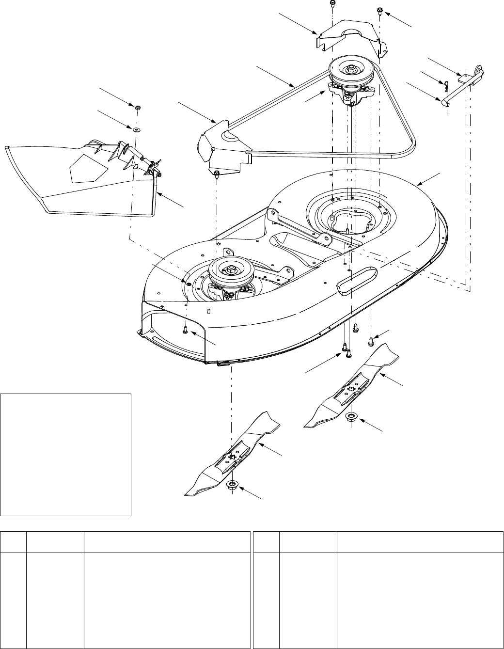
36
Models 650 & 652
†
Refer to
E
†
on Page 30
14
13
17
16
11
11
10
E
†
1
2
97
12
15
8
8
6
6
4
5
3
REF.
NO. PART
NO. DESCRIPTION
1 618-0138A Spindle Assembly
2 683-04003A Deck Shell
3 710-0726 Self-tapping Screw, 5/16-12 x .75
4 710-1260A Screw, 5/16-18 x .75
5 710-1611B Self-tapping Screw, 5/16-18 x .75
6 712-0417A Hex Flange Nut, 5/8-18
7 714-04023 Internal Cotter Pin, .080 x 1.56
8 742-0610A Blade, 21.23”
9 747-04018A Deck Hanger Link/Anti-sway Rod
10 754-0329A Deck Belt
11 783-04148A Belt Cover
12 783-04211 Anti-sway Stabilizer Bracket
13 736-0270 Bell Washer, .265 x .75 x .062
14 712-3006 Hex Nut, 1/4-20
15 726-0233 Push Nut, 1/4
16 731-1032B Discharge Chute Assembly
17 710-0751 Hex Cap Screw:1/4-20 x .620
REF.
NO. PART
NO. DESCRIPTION
IMPORTANT:
For a proper
working machine, use
Factory Approved Parts.
V-belts are designed to
engage and disengage
safely. A substitute (non
OEM) V-belt can be
dangerous by not
disengaging completely.
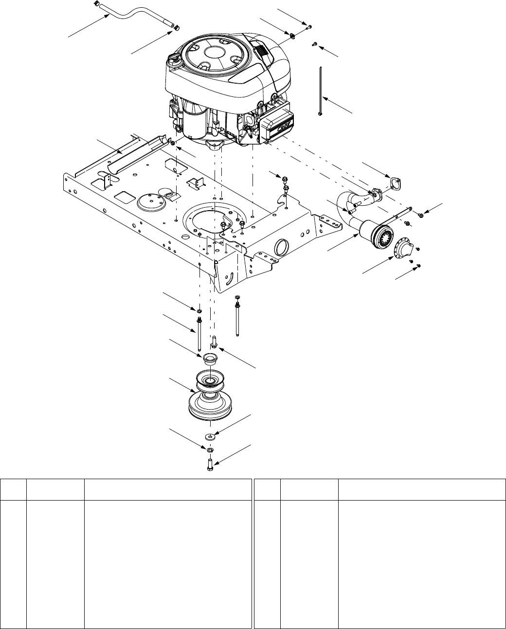
37
18
21
20
23
22
19
12
6
2
17
16 1
8
9
12
5
10
13
15
11
7
REF.
NO. PART
NO. DESCRIPTION
1 710-1502 Screw, #8-18 x .375
2 710-0599 Self-tapping Screw, 1/4-20 x .5
3 710-0726 Self-tapping Screw, 5/16-12 x .75
4 710-1237 Screw, #10-32 x .625
5 710-1314A Socket Cap Screw, 5/16-18 x .625
6 710-1315 Self-tapping Screw, 3/8-16 x 1.25
7 731-1682A Oil Drain Sleeve
8 751-9986 Muffer, Single Inlet
9 721-0208 Exhaust Gasket
10 726-0205 Hose Clamp, .490
11 712-0271 Hex Sems Nut, 1/4-20
12 736-0119 Lock Washer, 5/16
13 751B213146 Casing Clamp
14 725-0157 Cable Tie
15 751-0535 Fuel Line Hose
16 751B222261 Muffler Deflector
17 710-0456 Screw, #10-16 x .5 (Throttle Stop)
18 710-3029 Hex Screw, 7/16-20 x 1.25
19 711-1044 Belt Keeper Pin, 5/16 x 4.75
20 736-0171 Lock Washer, 7/16
21 736-0322 Flat Washer, .450 x 1.25 x .164
22 750-0956 Spacer, 1.0 x 1.4 x .825
23 756-04023 Engine Pulley, 3.12 x 5.56
REF.
NO. PART
NO. DESCRIPTION
3
14
4
Models 650 & 652
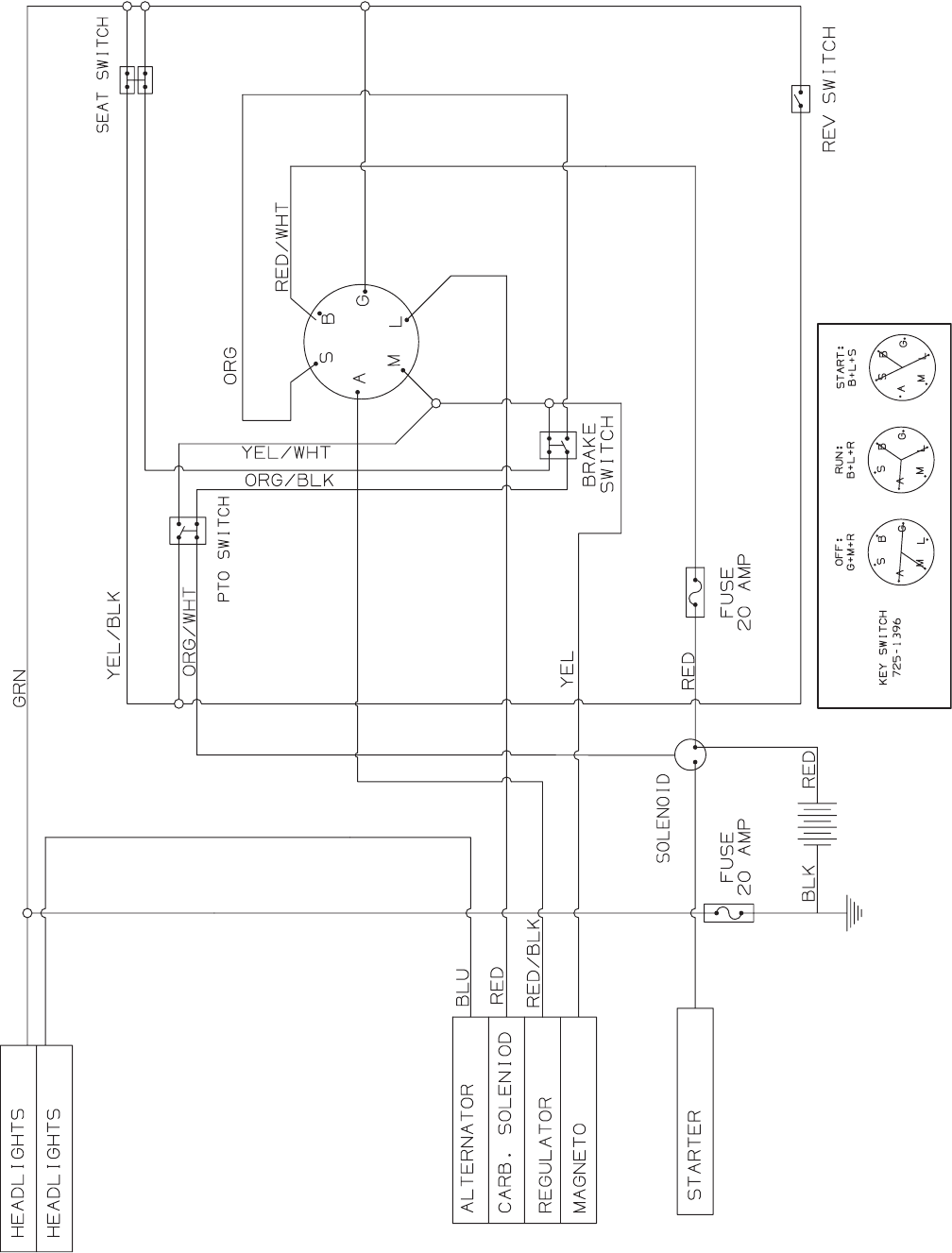
38
Models 650 & 652

39
NOTES

MANUFACTURER’S LIMITED WARRANTY FOR:
The limited warranty set forth below is given by MTD LLC with
respect to new merchandise purchased and used in the
United States, its possessions and territories.
“MTD”warrants this product against defects in material and
workmanship for a period of two (2) years commencing on the
date of original purchase and will, at its option, repair or
replace, free of charge, any part found to be defective in
materials or workmanship. This limited warranty shall only
apply if this product has been operated and maintained in
accordance with the Operator’s Manual furnished with the
product, and has not been subject to misuse, abuse,
commercial use, neglect, accident, improper maintenance,
alteration, vandalism, theft, fire, water, or damage because of
other peril or natural disaster. Damage resulting from the
installation or use of any part, accessory or attachment not
approved by MTD for use with the product(s) covered by this
manual will void your warranty as to any resulting damage.
Normal wear parts are warranted to be free from defects in
material and workmanship for a period of thirty (30) days from
the date of purchase. Normal wear parts include, but are not
limited to items such as: batteries, belts, blades, blade
adapters, grass bags, rider deck wheels, seats, snow thrower
skid shoes, shave plates, auger spiral rubber and tires.
HOW TO OBTAIN SERVICE: Warranty service is available,
WITH PROOF OF PURCHASE, through your local authorized
service dealer. To locate the dealer in your area, check your
Yellow Pages, or contact MTD LLC at P.O. Box 361131,
Cleveland, Ohio 44136-0019, or call 1-800-800-7310 or 1-
330-220-4683 or log on to our Web site at
www.mtdproducts.com.
This limited warranty does not provide coverage in the
following cases:
a. The engine or component parts thereof. These items
may carry a separate manufacturer’s warranty. Refer
to applicable manufacturer’s warranty for terms and
conditions.
b. Log splitter pumps, valves, and cylinders have a
separate one year warranty.
c. Routine maintenance items such as lubricants, filters,
blade sharpening, tune-ups, brake adjustments, clutch
adjustments, deck adjustments, and normal
deterioration of the exterior finish due to use or
exposure.
d. Service completed by someone other than an
authorized service dealer.
e. MTD does not extend any warranty for products sold or
exported outside of the United States, its possessions
and territories, except those sold through MTD’s
authorized channels of export distribution.
f. Replacement parts that are not genuine MTD parts.
g. Transportation charges and service calls.
No implied warranty, including any implied warranty of
merchantability of fitness for a particular purpose,
applies after the applicable period of express written
warranty above as to the parts as identified. No other
express warranty, whether written or oral, except as
mentioned above, given by any person or entity,
including a dealer or retailer, with respect to any product,
shall bind MTD. During the period of the warranty, the
exclusive remedy is repair or replacement of the product
as set forth above.
The provisions as set forth in this warranty provide the
sole and exclusive remedy arising from the sale. MTD
shall not be liable for incidental or consequential loss or
damage including, without limitation, expenses incurred
for substitute or replacement lawn care services or for
rental expenses to temporarily replace a warranted
product.
Some states do not allow the exclusion or limitation of
incidental or consequential damages, or limitations on how
long an implied warranty lasts, so the above exclusions or
limitations may not apply to you.
In no event shall recovery of any kind be greater than the
amount of the purchase price of the product sold. Alteration
of safety features of the product shall void this warranty.
You assume the risk and liability for loss, damage, or injury to
you and your property and/or to others and their property
arising out of the misuse or inability to use the product.
This limited warranty shall not extend to anyone other than the
original purchaser or to the person for whom it was purchased
as a gift.
HOW STATE LAW RELATES TO THIS WARRANTY: This
limited warranty gives you specific legal rights, and you may
also have other rights which vary from state to state.
IMPORTANT:
Owner must present Original Proof of
Purchase to obtain warranty coverage.
MTD LLC, P.O. BOX 361131 CLEVELAND, OHIO 44136-0019; Phone: 1-800-800-7310, 1-330-220-4683
