MTD Walk Behind Lawnmower, Gas Manual WL000313
User Manual: MTD MTD Walk Behind Lawnmower, Gas Manual MTD Walk Behind Lawnmower, Gas Owner's Manual, MTD Walk Behind Lawnmower, Gas installation guides
Open the PDF directly: View PDF ![]() .
.
Page Count: 32

Operators Manual
Model Series
370 thru 389
Rotary Mowers
IMPORTANT:READSAFETYRULESAND INSTRUCTIONSCAREFULLY
Warning: This unit is equipped with an internal combustion engine and _hou[d not be used on or near ally unimproved foresl-
CoMered, _3FUSII_Covor ed Or g_a_s-_v_rgd IB+ndfJrl(ess IE1_ _noit3_'s exhaust Sy_tsyt_ is {_qul{3p_ WItll _ _p_ fl/_Ir_t_r m¢3OliD_
addllo_dle Iooal or Glat_ raw8 Ill any). if aspark arrestor is used, II sl_ouid be malnlait_ hi eflectIve working order by the operator,
In the SLat_ Of Oalifornl_.Ih_ abavo is required DV law ISeclion 4442 of the CEtlilorr_ia Public Resources Code) Other s t_te,_ rosy hays
similar laws. Federal laws apply on federal land_. A spa_ arrestor for tile muffler is awii_ble Ihro_lgh your nearest _nglne =lktlhorlz ed
service de_ler or conlact the service dep_rtmer_t, PO. 19o_ 368022 _levoland. Ohio 44136-g722
MTD PRODUCTS INC. P.O. BOX 368022 CLEVELAND, OHIO 44136-9722
PRINTED rN U.S.A. FORM NO. 770-10114
(10/98)
SECTION 1: FINDING YOUR MODEL NUMBER
This Operator's ManL_al is an important pert of your new walk behhld. It will help you assemble, prepare alqd
maintain your walk behind. Please read and understand what it says,
Before you start to prepare your walk behind for ds first use, please locate the model plate and copy the
ihformaiien from It in this Operator's Manual. The Information on the model pla[e is very important if you need
help from your dealer or the MTD CLlstomer support department.
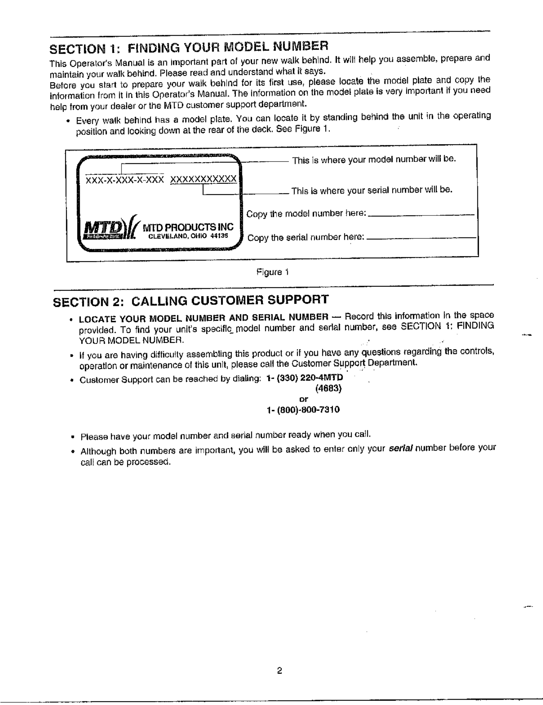
Every' walk behind has amodel plate, You can Io_afe it by standing behirM the unit in the operating
position and looking down at the rear of the deck. See Figure 1.
×XX-X-XXX-X-XXX XXXXXXXXXXX
This is where your model number will be.
- This is where your serial number will be.
Copy the model nLImber here:
Copy the serial number here:
Figure 1
SECTION 2: CALLING CUSTOMER SUPPORT
•LOCATE YOUR MODEL NUMBER AND SERIAL NUMBER -- Record this information fn the space
provided. To find your unit's specific model number and eedal n_mber, see SECTION 1: FINDING
YOUR MODEL NUMBER.
• If you are having dLfficulty assembling this product or if you have any questions regarding t_e controls,
operation or maintenance Of this unit, please call the Customer Support Department,
• Customer Support can be reached by dialing: 1- 1330) 2204MTD
(4683)
or
1- (800)-800-7310
• Please have your model number and serial number ready when you call.
• Although both numbers are irnport_nt, you Wffl be asked to enter only your sofia/number before your
ee.II can be processed.
SECTION 3: IMPORTANT SAFE OPERATION PRACTICES
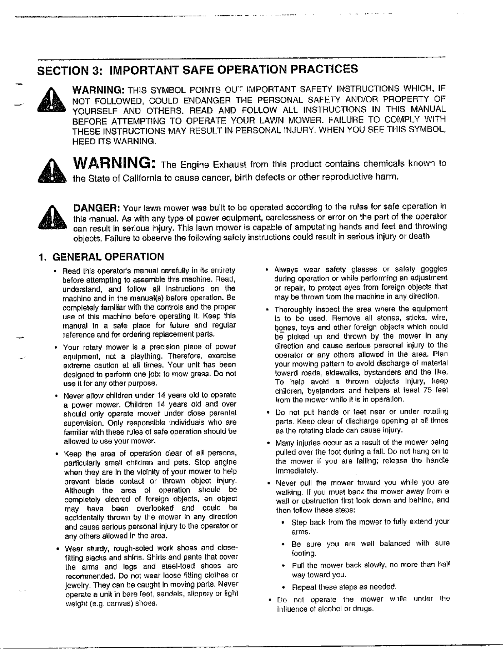
,ikWARNING: THIS SYMBOL POINTS OUT IMPORTANT SAFETY INSTRUCTIONS WHICH, IF
NOT FOLLOWED, COULD ENDANGER THE PERSONAL SAFETY AND/OR PROPERTY OF
YOURSELF AND OTHERS. READ AND FOLLOW ALL INSTRUCTIONS IN THIS MANUAL
BEFORE ATTEMPTING TO OPERATE YOUR LAWN MOWER. FAILURE TO COMPLY W[TH
THESE INSTRUCTIONS MAY RESULT IN PERSONAL INJURY. WHEN YOU SEE THIS SYMBOL,
HEED ITS WARNING,
WARNING: The Engine Exhaust from this product contains chemicals known to
the State of California to cause cancer, birth defects or other reproductive harm.
DANGER= Your lawn mower was built to be operated according to the rulas for safe operation in
this manual. As with any type of power equipment, carelessness or error on the part of the operator
can result in serious injury. TMs lawn mower is capable of amputating hands and feet and throwing
objects. Failure to observe the following safety i£struotlons could result in serious injury or deatl)
1. GENERAL OPERATION
•Read this operator's manual carefully in its entirety
before attempting to a68emble this machine. Read,
understand, and follow all instructions on the
machine and in the manual(s) before operation. Be
completely familiar with the controls and the proper
use of this machine before operating It Keep this
manual in a safe place for future and regular
reference and for ordering replacement parts,
• Your rotary mower is a preelston piece of power
equipment, not a plaything. Therefore, exorcise
extreme cautton aL all limes. Your unit has been
designed to perform one job: to mow gross• DO not
use if for any other purpose,
• Never allow children under 14 yea_s old to operate
a power mower. Children 14 years old and over
should only operate mower under close parental
supervision. Only responsible {ndividuals who are
familiar with these rules of safe operation should be
allowed to use your mower,
, Keep the area of operation clear of all persons,
particularly small children and pets. Stop engine
when they are ]n the vicinity of your mower to help
prevent blade contact or th_wn object inJury,
Although the area of operation should he
compLetely cleared of foreign objects, an object
may have been ovedeoked and could he
accldenlally thrown by the mower in any direc_ton
and cause serious personal injury to the operator or
any others allowed in the area.
• Wear sturdy, rough-soled work shoes and close-
fitting slacks and shirts. Shirts and pants that cover
the arms and legs and steel-teed shoes are
recommended. Do noL wear loose fitting clelhes or
Jewelry They can be caught In moving parts, Never
operate aunit in bare feet, sandals, slippery or light
weighL(eg cenvas) shoes
• Always wear eatery glasses or safely goggles
during operation or while pertorrning an adjustment
or repair, to prefect eyes from foreign objects that
may be thrown from the machine in any direction.
•Thoroughly inspect the area where the equipment
i_ to he used¸ Remove all stones, sticks, wire,
I_o_nes, toys and other foreign ebject_ which could
be picked up and thrown by the mowe_ in any
direction and cause serfou8 personal injury to the
operator or any Others allowed in the areEt, Plan
your mowing pattern to avoid dl_charg_ of material
toward roads, sidewalks, bystanders and the like,
TO help avoid a thrown objects Injury. keep
children, by6thnd_rs anrf helpers at least 75 feet
Sore the mower while g i6 i_ opertalon.
°DO riot put band8 or leer near or under rotating
ports¸ Keep clear of discharge opening at al! times
e_ the rotating blade can cause injury.
• Many injuries occur as a result of the mower being
pulled over the foot dudng a fall. Do not hang on to
the mower if you are falling; release the h_ndIe
iinmediately
• Never pull the mower toward you while you are
walking If you must back the mower away from a
walt or obstruction first took down and behind, and
then fellow these 8tops:
.Step back from the mower to, frilly extend your
arm_.
•Be SLate you are well balanced with sure
fooling.
• Puff the mower back slow_y, no moRe than haq
way toward yOL_.
• Repeat these siege a9 needed¸
• Do n_l e_eralo the mower while under Ihe
Influence o_ alcohol or drugs.
•DO not engage the self-prabelled mechanism cn
units so equipped while sthrLing engine,
•The blade control handle is a safety device Never
attempt to bypass its operagon. Doing so makes
the safety device inoperative and may result in
personal in{ury through contact with the rotating
blade. The blade control handle must operate
easily in both direntions and autornatically return te
the disengaged poaltfon when released,
• Never operate the mower in wet grass. Always be
sure of your footing. A slip and far can cause
sedous personal thjur), Keep a firm hold on the
handle and walk, never run. If you feel you are
losing your footing, RELEASE THE BLADE
CONTROL HANDLE IMMEDIATELY and the blade
will stop rofahng within three seconds.
•Mow only in daylight or good artificial light.
• Stop the blade when croe81ng gravel drives, walks
or roads,
• If the equipment shoald start to vibrate abnormally,
stop the engine and check immediately for the
cause, Vibration is generally a warning at trouble,
• Shut the engine off and wait until the blade comes
to a complete stop before removing the grass
eel=her er unclogging the chute, The cut_ng blade
continues to rotate for a few seconds after the
engine is shut off. Never place any part of the body
in the blade area until you are sure the blade has
stopped rotabng,
• Never operate mower without proper guards, grass
catcher, plates or other safety protective devices in
place.
• Muffler and engine become hot and can cause a
burn, DO not touch.
• Only use accessories approved for this machine by
the manufaablrer. Read, understand, and Iollow all
]nstruc_ens provided wgh the abprovab accessory.
• If siluations occur which are not covered Jn this
manual, use care and good judgment. Contact your
dealer for assistance Telephone 1-800-800-7310
for the name of your nearest dealer,
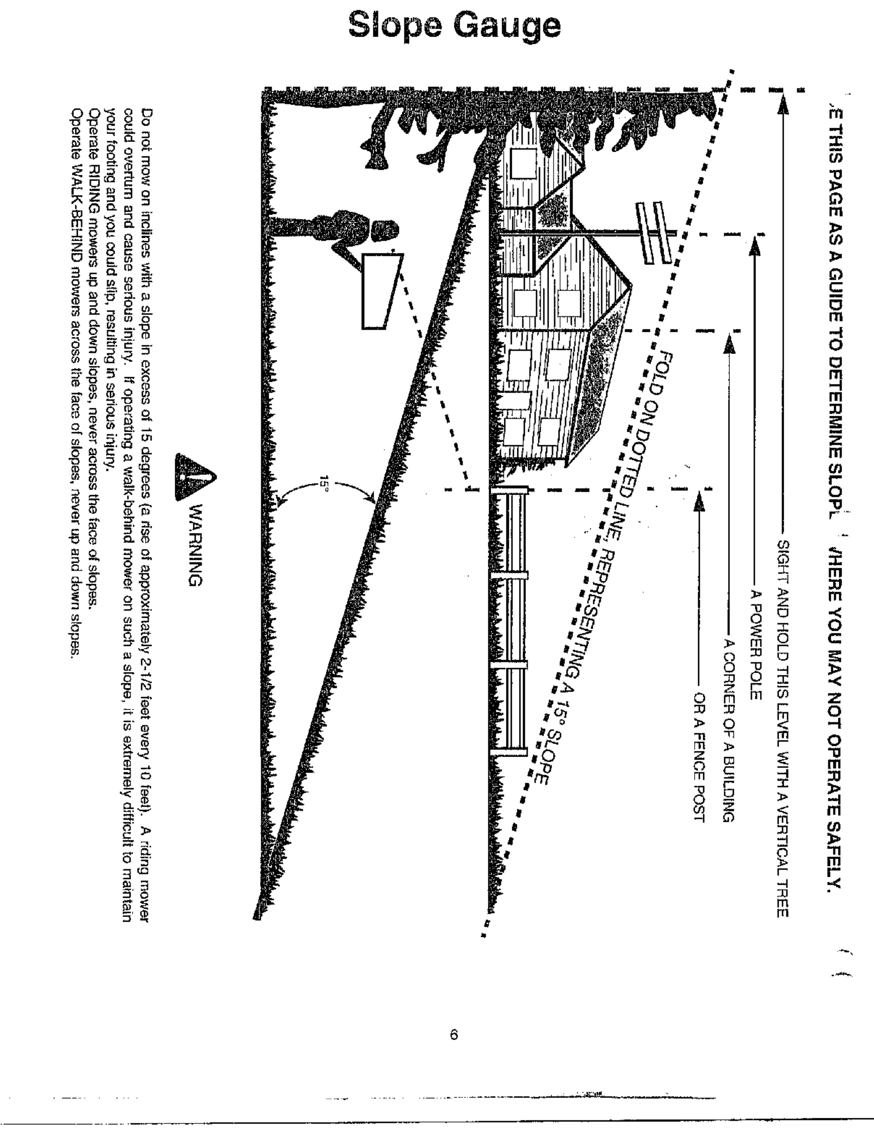
2, SLOPE OPERATION
For your safety, use the slope gauge included as pad of
this manual _e measure sJopes before oper_ing fhfs unit
on a eloped or hilly area. If the _lope is greater than 15
degrees as shown on the slabe gauge, do not operate this
ung on that area or serious inlury could result.
DO:
• Mew across the face of slopes; never uo and down.
E_ercise extreme osugen when changing direction
on slopes.
• Watch for holes, ruts, hidden objects, or bumps.
Tall grass can hide obstacles.
• A_ways be sur_ of your footing. A alip and fall can
cause serious personal injury¸ if you feel you are
losing your balance release the blade control
handle immediately and the blade will stop in less
than 3seconds.
DO NOT:
• Do not mow near drop-offs, ditches or
embankments, The operator could [ose foogng or
balance.
• De net mow slopes greater than 15 degrees as
shown on the slope gauge.
• DO not mow on wet grass. Reduced footing could
cause slipping.
3. CHILDREN
Tragic accidents can occur if the operator is not alert to the
presence of children, Children are eden aLtracted to the
mower and the mowing activity. Never assume thai
children will remain where you last _aw them,
• Keep children out of the mowmg ares and under
the watabthl care of a responsible adult other than
the operator.
• Be alert and turn mower off if a chad enters the
area,
• Before and while moving backwards, look behind
and down for small children or othe_" object _.
• Never atlow children under age14 to operate the
mower. Children 14 years of age and above
should read and understand the operation
instrucgons and safety rules in this rns.nuaL
• Use extreme care when approaching blind comets.
shrLths_ trees, or other objeOt_ that may obscure
your vision of a child or hazard,
4. SERVICE
• Use extreme care in handling gasolthe and other
feels. They are extremely flammable and the
vapors are explosive.
• Use only an 8pthoved gasoline co[ltathe_
• Never remove gas cap or add fuel while the engine
is running, Allow engine to cool at least two
minutes before refueling.
• Replace gasoline cap securely and wipe off any
spbled gasoline before starting the engine as [t may
cause a fire or explosion,
• Ext]nguiab all cigarettes, cigars, pipe8 and other
sources of ignition
• Never retoel machine indoors because flammable
vapors will ,_ccumala[e in the area,
• Never store the machine or fuel ¢o_iner inside
where there is an open flame or spark such as a.
gas water heater, space heater or furnace.
• Never run _.n engine inside & calsed ares.,
•TO reduce life hazard, _eep mower free of grass,
leaves, or other deeds build-up. Clean up oil or fuer
spillage. Allow m_Jwer to cool at least 5 minutes
LgefQre storing.
• Before cleanirlg, repairitTg, or inspecting, make
c_rtain the blade _rld eli moving parts have
stopped. Disconnect the 3park plug wire, and keep
the wire away from the 8park plug to prevent
accidental _tartfog.
• Chock the blade and engine mounting bolt_ at
Irequent intervals for proper tlghtne._s. Also,
alsually inspect blade for damage (e.g,, bent,
cracked or worn). Replace with btade which meets
original equipment spec_ficeffons listed in this
marlua].
• Keep all nuts, bolts, and screws tight to be sure the
equipment Is In safe working condition.
• Never tamper with safety devices. Check their
proper operation regularly.
• After striking a foreign object, stop the etlglne,
remove the wire from the spark p_u_, and
thoroughly inspect _he mower for any damage.
Repair the damage before stantng and eperefing
the mow0r.
• Never attempt to make a wheel or cutting height
adiustment while the engine is runr_ing
• Grass catcher components are subject to wear,
damage arid dcterioreffon, which could expose
movirlg patts or alfow objects to be thrown. For
safety protection, frequently check components and
replace with manuf&ct[Jrer's recommended parts,
whgn necessary.
• Mower btedes are sharp and can cut. Wrap the
blade(s) or wear gfov_'s, and t_e extra cautfo_
when servicing them.
• Do not change th_ engine gawmor setting or
overs_oeq the engine. Excessive engine speeds
are dartgereus.
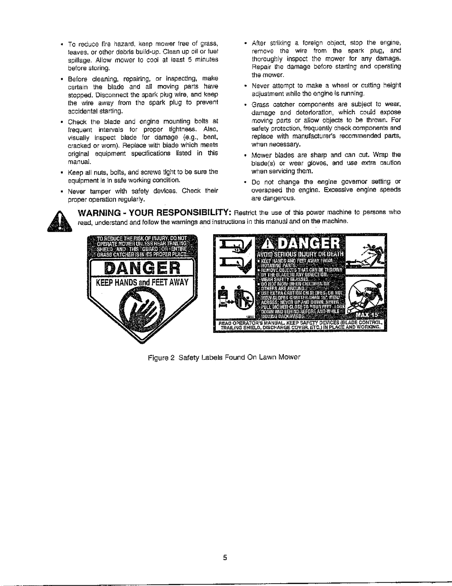
WARNING -YOUR RESPONSIBILITY: RestrFct the use of this power machine to persons who
re_d, undersandaag oowthewarnmgsaed nsructons n h'smaRu_aRdonthemachne.
DANGER
Figure 2 Safety Labels Found On Lawn Mower
Saope Gauge
6
SECTION 4: UNPACKING INSTRUCTIONS
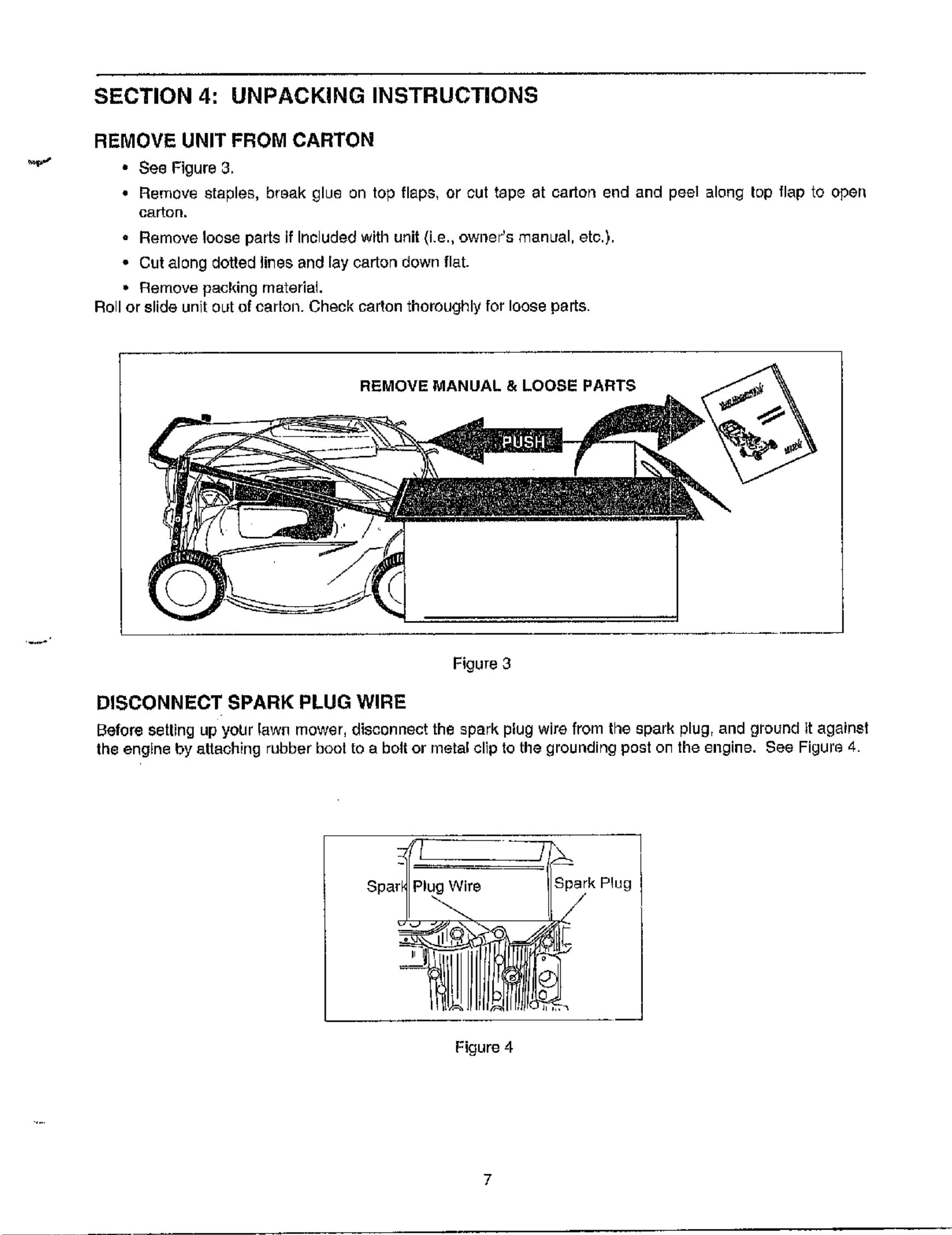
REMOVE UNIT FROM CARTON
• See Figure 3,
•Remove staples, break glue on top flaps, or cut tape at oarto_ end and peel along top flap to open
carton.
• Remove loose parts if Included with unit (i.e., owner's manual, etc.).
• Cut along dotted lines and lay carton down flat.
• Remove packing material
Roll or slide unit out of carlon. Check carton thoroughly for loose parts.
REMOVE MANUAL & LOOSE PARTS
Figure 3
DISCONNECT SPARK PLUG WIRE
Before setting up your lawn mower, disconnect the spark plug wire from the spark plug, and ground it against
the engine by attaching rubber boot to abolt or metal clip to the grounding post on the engine, See Figure 4.
Spark Plug
Figure 4
SECTION 5: SET-UP INSTRUCTIONS
This guide covers models 370 -379 single speed self propelled mowers and 380 - 389
six speed self propelled mowers. Much of this guide pertains to both models.
However, there are some areas where only one model is covered. Use only the
information that is appropriate for your model.
ITEMS REQUIRED FOR ASSEMBLY
•PairefPliers(Notnocessary, butheipful)
• Motel Oil
•Fresh Gasoline
IMPORTANT: This unit is shipped WITHOUI GASOLINE or OIL {ll the e!_gine. Be certain to service
engine with gasoline and oil as instructed in the separate engine manual before operating your mower.
NOTE; Relerence to right or loft hand side of the mower is observed from the operating position,
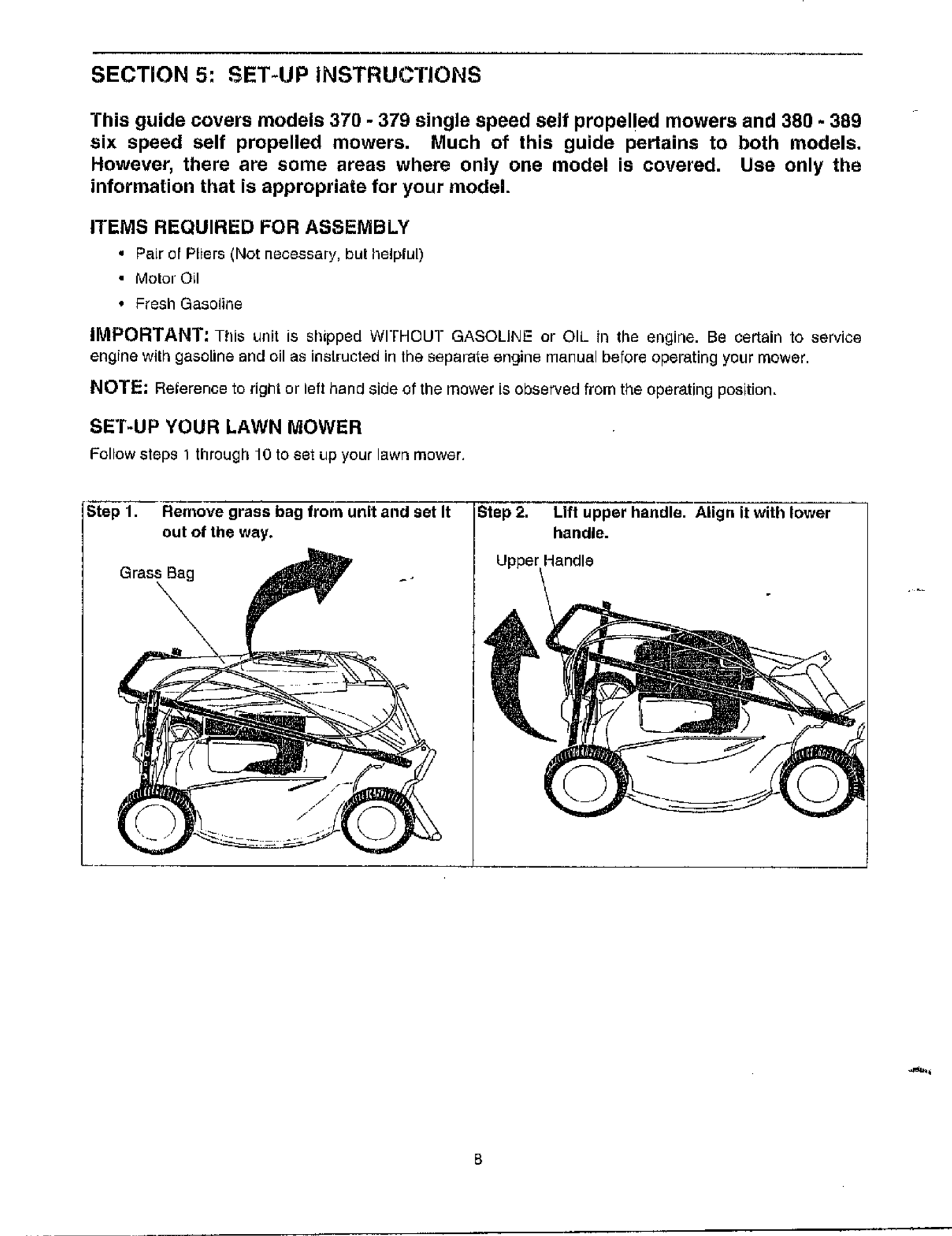
SET-UP YOUR LAWN MOWER
Follow steps 1 through10 to set up your lawn mower.
S_ep_'_ Re;er_ve grass bag from unit and set It
out of the way.
Grass Bag -.
\
IStep 2, Lift upper handle. Align it with lower
I UpperC,':
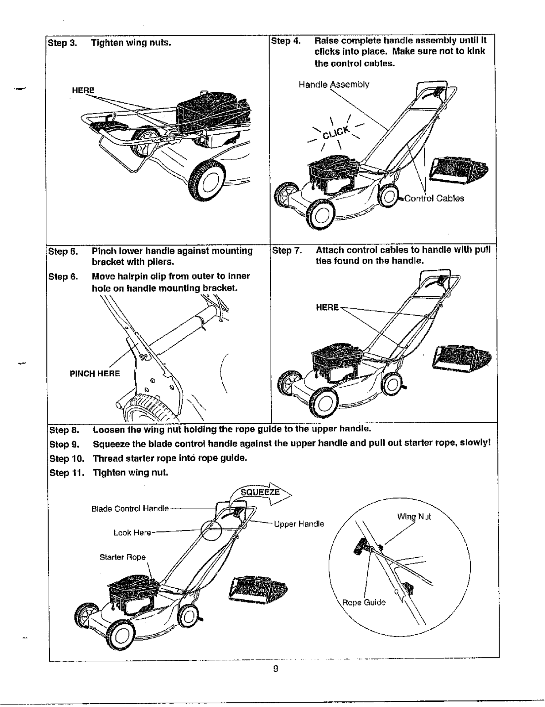
Step 3. Tighten wing nuts.
Step 5.
Step 6.
Step 4, Raise complete handle assembly until It
clicks into place. Make sure not to kink
the control cables.
Handle Assembly
Pinch lower handle against mounting
bracket with pliers,
Move hairpin clip from outer to inner
hole on handle mounting bracket.
G
PINCH ERE
Step 7, Attach control cables to handle with pull
ties found on the handle.
NE== 7
Step 8. Loosen the wing nut holding the rope guide to the upper handle.
Step g. Squeeze the blade control handle against the upper handle and pull out starter rope, slowly!
Step 10. Thread starter rope into rope guide.
Step 11. Tighten wing nut.
Blade Control Hat, die
Upper Nandle
Starter Rope
_Rope Guide /
9
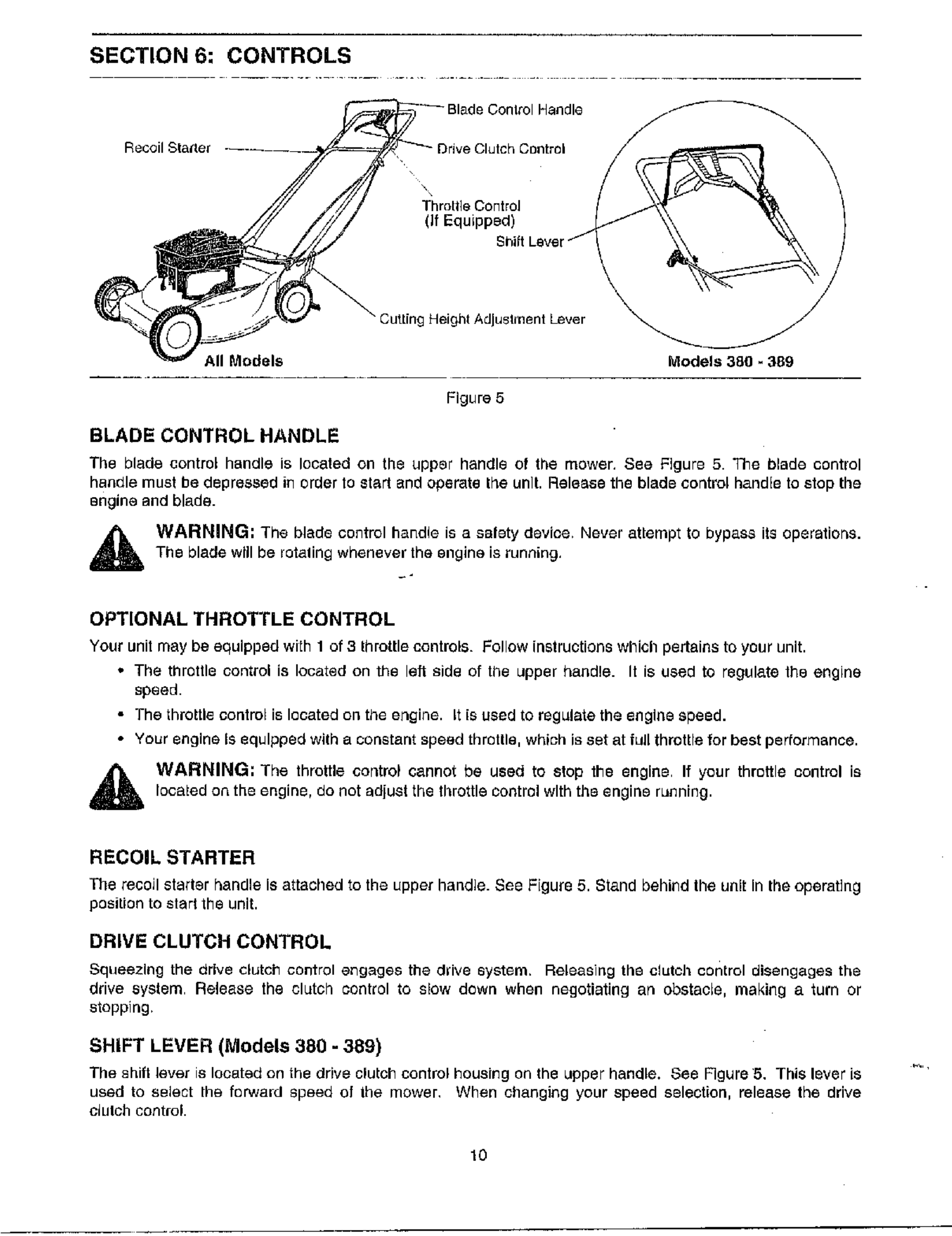
SECTION 6: CONTROLS
Blade Conlrol HaNdl+__
Recoil Starter , , _ five Clutch Control
(If Equipped) "'
Throttle Control
All Models Models 380 - 389
Figure 5
BLADECONTROLHANDLE
The blade control handle is located on the upper handle of the mower, See Figure 5. The blade control
handle must he depressed in order to 8tart _nd operate the unit. Release the blade control handle to stop the
engine and blade.
WARNING; The blade control handle is a salety device. Never attempt to byp_.ss its operations.
The blade will he rotaling whenever the engine is running,
OPTIONAL THROTTLE CONTROL
Your unit may be equipped with 1of 3throttle controls. Follow instructions which pertains to your unit.
• The throttle control is located on the left side of tile upper handle. It is used to regul&te the engine
speed.
•The throttle control is located on the engine, it [s used to regulate the engine speed.
• Your engine Is equipped wgh a constant speed thretlle, which is set at full throttle for best performance.
WARNING; The throttle control cannot be used to stop the engine If your throttle control is
located on the engine, do not adjust the throftle control with the engine running.
RECOIL STARTER
The recoil starter handle Is attached to the upper handle. See Figure 5. Stand behind the unit In the operating
position to start the unit.
DRIVE CLUTCH CONTROL
Squeezing the drive clutch control engages the ddve eystem. Releasing the clutch control disengages the
drive system Release the clutch control to slow down when negotiating an obstacle, making a turn or
stopping.
SHIFT LEVER (Models 380 -389)
The shift lever is located on the drive clutch control housing an the upper handle. See Figure 5. This lever is
used to select the ferwald speed of the mower, When changing your speed selection, release the drive
clulch control.
10
NOTE: Only move the shift lever when the engine is running. Changing the shift lever setting with the
engine off can cause damage to the mower.
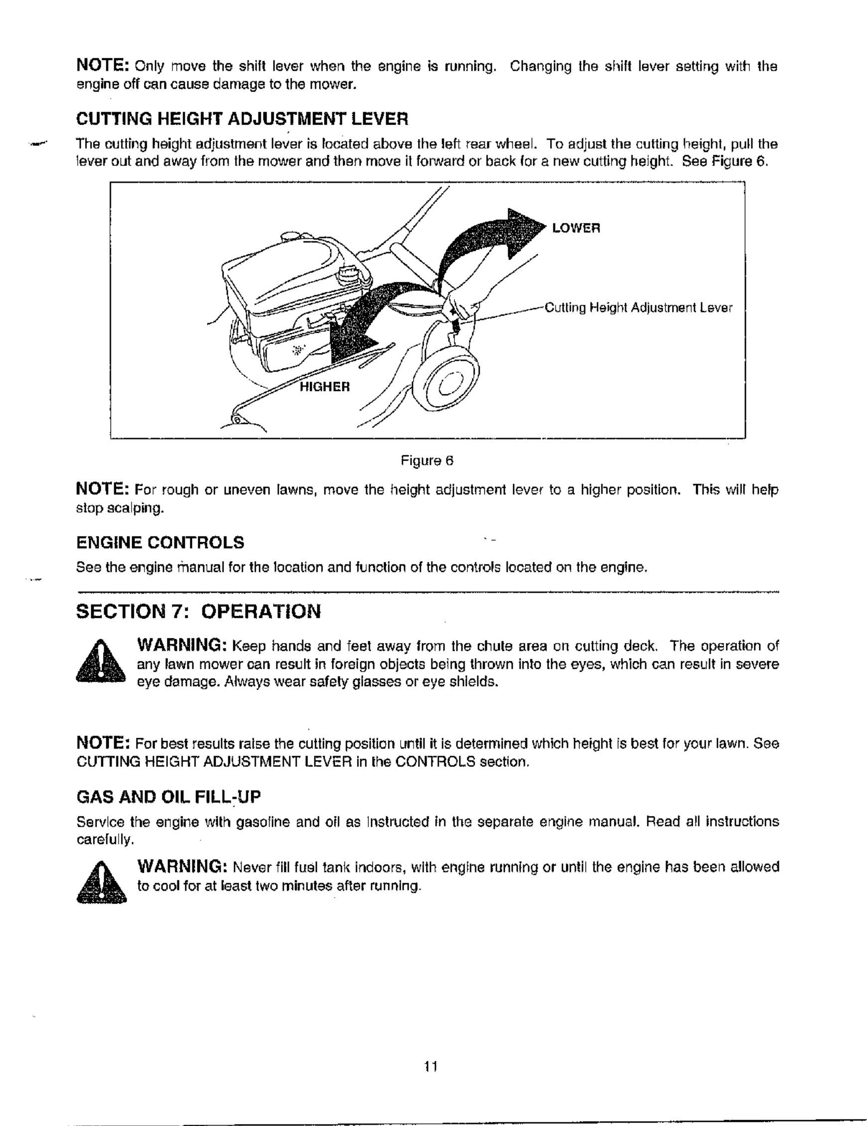
CUTTING HEIGHT ADJUSTMENT LEVER
The cutting height adiustment lever is located above the left rear wheel. To adjust the culting height, pull the
lever out and away from lhe mower and then move it forward or back for a new cutting height. See Figure 6.
gHeight Adjustment Lever
Figure 6
NOTE: For rough or uneven lawns, move the height adjustment lever to a higher position. This will help
stop scalping.
ENGINE CONTROLS
See the engine manual for the Iooationand funclionof the controls located on the engine.
SECTION 7: OPERATION
_lb WARNING: Keep bands and feet away from the chule area on cutting deck. The operation of
any lawn mower can result in foreign objects being thrown into the eyes, which can result in severe
eye damage. Always wear safety glasses or eye shields.
NOTE: For best results raise the cutting position until it is determined whlch height is best for your lawn. See
CUqI'FING HEIGHT ADJUSTMENT LEVER in the CONTROLS section.
GAS AND OIL FILL;UP
Service the engine with gasofine and oil as Instructed tn the separate engine manual. Read all instructions
carefully.
WARNING: Never fill fuel tank indoors, with engine running or until the engine has been allowed
to cool for at least two minutes after running.
EACH TIME BEFORE YOU START YOUR MOWER
•Altach spad_ plug w_re [o spark plug. Make cerLein the metal cap on the end of the spark plug wire is
fastened securely over the metal tip on the spark plug.
,Check for proper drive clutch operation usin9 the NEUTRAL ADJUSTMENT TEST.
NEUTRAL ADJUSTMENT TEST
To pedorm the NEUTRAL ADJUSTMENT TEST answer the following questions.
• With the drive clutch control released, push mower iorward and pull it baekwerd. Does it move freely?
• Squeeze Ihe drive clutch control an_ pull the mower backward, Do the rear wheels lock (not turn)?
• Is the drive clutch control cable free of kinks or sharp bends?
If you answered "yes" to all three questions, your mower passed the test and you can start your mower. If
you answered "no" to any of the three questions, you need to go through the DRIVE CLUTCH CONTROL
ADJUSTMENT found in the ADJUSTMENTS section
TO START ENGINE AND ENGAGE BLADE
• Move the throttle control lever, if equipped, air the way to the last position,
*Prime engine as instructed in the separate engine manual,
•BtandbehlndtheuniL squeezeandholdthebladecontrolhandleagainsttheupperhandle,
•Grasp starter handle and pull rope out slowly unk] engine reaches start of compression cycle (rope will
pull slightly harde¢ at this point). Let the rope rewind slowly.
• Pull rope with a rapid, cominuous, {ull arm stroke, Keep a firm grip on starter handle. Return it slowly to
the rope guide.
• After engine starts, move throttle control to desired engine speed. (The mower Is designed to be
operated at full throttle)
NOTE: If any problems are encountered, refer to the TROUBLE SHOOTING 8ection of this manuel,
TO STOP ENGINE AND BLADE
• Release the blade control dandle to stop the engine and blade.
WARNING: The blade continues to rotate for a few seconds after the engine is shut off.
USING YOUR ROTARY MOWER
Be sure lhaL lawn is clear of stones, sticks, wire, or olher obiects which could damage the lawn mower er
e_gine. Su6h objects could he eccide_ltly thrown by the mower in any direction and gauss serious personal
injury to the operator and others.
For the best resugs, do not out wet grass beoause it tends to stick to the underside of the mower, preventing
proper discharge of grass clippings, and could cause you to slip and fall New grass, thiok grass or wet g_ss
may require a n_rrower cut,
For a healthier lawn, never cut og more than one-third of the total length of the graee. YoLir lawn should be cut
in the lall as long as there is growth.
This mower is designed to be operated at full Ihrotge [o give you the beet cut and do the most effective job of
mowing or mulching,
WARNING: If you stbke a foreign object, stop the engine. Remove wire from spark pIug,
thoroughly inspect the mower for any damage, end repair the damage before restarting and
operating lhe mower. Extensive vibration of the mower during operation is an indication of damage.
The unit should be promptly inspected and repaired.
12
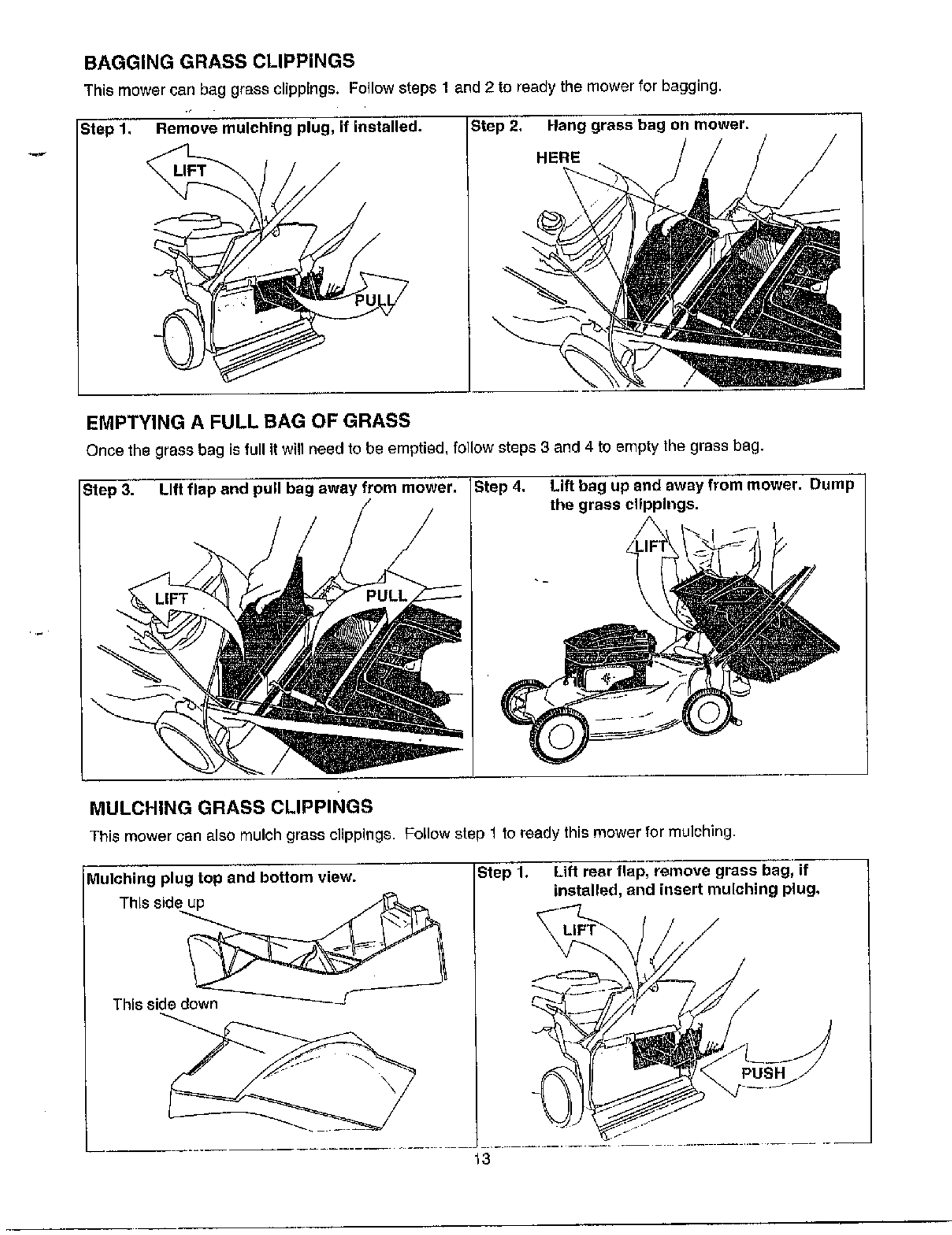
BAGGING GRASS CLIPPINGS
This mower can bag grass clippings. Follow steps 1 and 2 to ready the mower for bagging.
Step 1. Remove mulching plug, if installed. Step 2, Hang grass bag on mower.
HERE
EMPTYING A FULL BAG OF GRASS
Once he grass bag is full it wIIneed to be empt'ed, follow steps 3and 4 to empty the grass bag.
Step 4. Lift bag up and away from mower. Dump
the grass clippings.
MULCHING GRASS CLIPPINGS
This mower can also mulch grass clippings. Follow step to ready his mower fo mulch rig.
lu ching plug top and bottom v=ew.
This side up
This side down
Step 1. Lift rear flap, remove grass bag, if
installed, and nsert mulch'ng plug,
\
/
_3
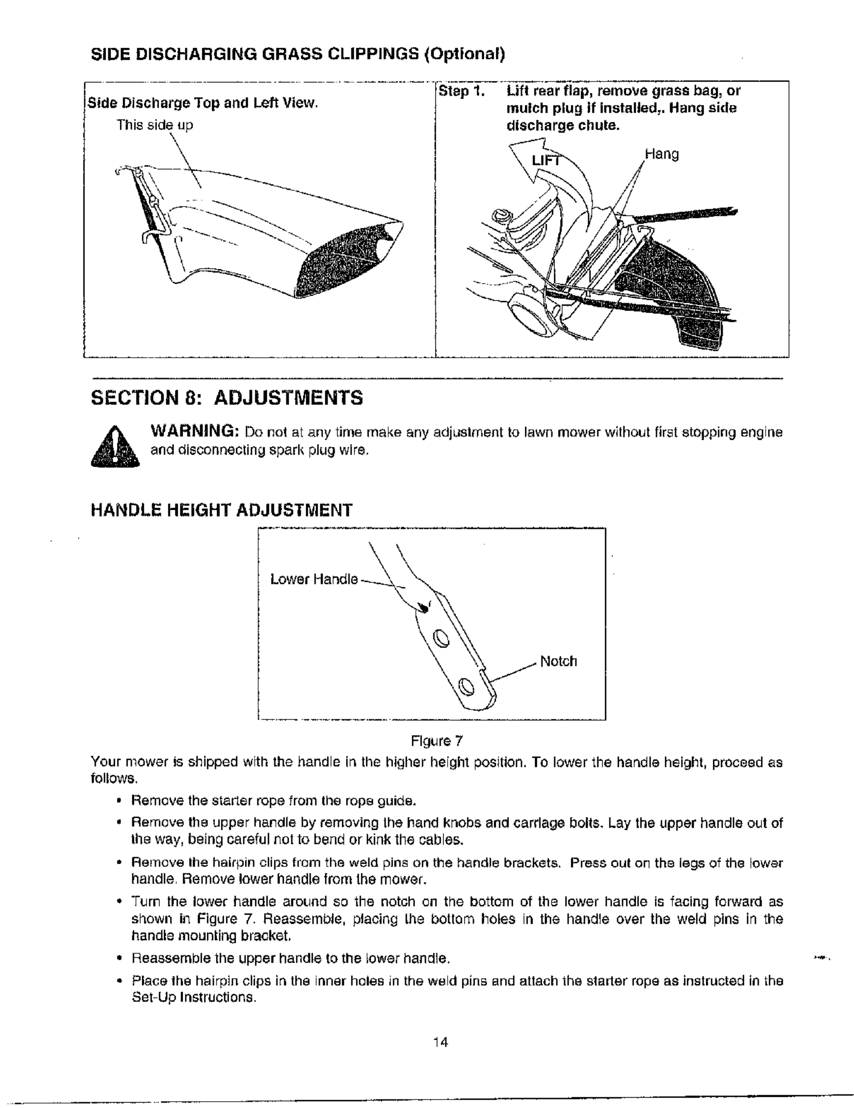
SIDE DISCHARGING GRASS CLIPPINGS (Optional)
F -- --_ ............ _:i'_p-l__" Lift r_aarflap, remove grass bag, or
iSide Discharge Top and Left V=ew.
This side up
mulch plug if installed,. Hang side
discharge chute.
Hang
SECTION 8: ADJUSTMENTS
WARNING; Do not at any time make any adjustment to lawn mower without first stopping engine
and disconnecting spark plug wire,
HANDLE HEIGHT ADJUSTMENT
r
Lower Handle _ Notch
FIgiJre 7
Your mower is shipped with the handle in the higher height position. TO lower the har_dle height, proceed as
follows.
,Remove the starter rope from the rop_ guide.
=Remove the upper handle by removing Ihe hand knobs end carriage bolts. Lay the upper handle out of
tile way, being careful not to bend or kink the cables.
•Remove Ihe hairpin clips from the weld pins on the handle brackets. Press out on thB legs of the lower
handle Remove lower handle from the mower.
•Turn the lower handle aroL_ad so the notch on the bottom of the lower handle is facing forward as
shown in Figure 7. Reassemble, placing [he bottom holes in the handle over the weld pins in the
handle mouniing bracket,
• Reassemble the upper handle to the lower handle.
•Place the hairpin clips in the inner holes in the weld pins and attach the starter rope as instructed in the
Set Up Instructions.
14
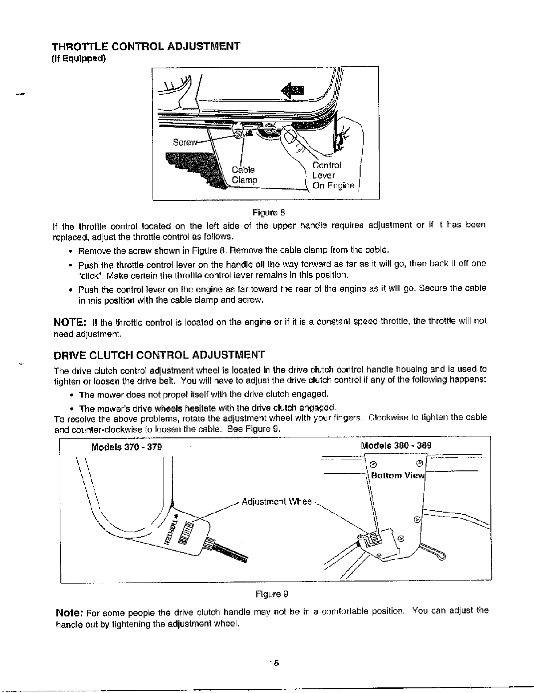
THROTTLE CONTROL ADJUSTMENT
(If Equipped)
On Engine
Figure 8
If the throttle control located on the left side of the upper handle requires adiLIstment or if It has been
replaced, adjust the throtge control as follows.
• Remove the screw shown in Figure 8. Remove the cable clamp from the cable.
• Push the throttle contrM lever on the handle all the way forward as far as it will go, then back it off one
"click". Make cerlain the thml_le control Iever remains in this position.
•Push the conti'ol lever on the engine as far toward the rear el the engine as it will go. Secure the cable
in this position with the oable clamp and screw.
NOTE: If the throttle control is located on the engine or if it is a constanl speed throttle, the throttle will not
need adjustment,
DRIVE CLUTCH CONTROL ADJUSTMENT
The drive clutch control adjustment wheel is located in the drive clutch control handle housing and is used to
tighten or loosen the drive belt. You will have to adjust the drive clutch contlol if any of the following happens:
•The mower does not propel itself with the drive clutch engaged
•The mower's drive wheels hesitate with Ihe drive clutch engsged.
To resolve the above problems, rotate the adjustment wheel with your fingers. Clockwise to tighten the cable
and eounler-clockwise to loosen the cable. See Figure £.
Models 370 -379 Models 380 * 38g
® ®
Figure 9
Note: For some people the drive clLJtch handle may not be in a comfortable position. You can adjust the
handle out by tightening the adjustment wheel,
15
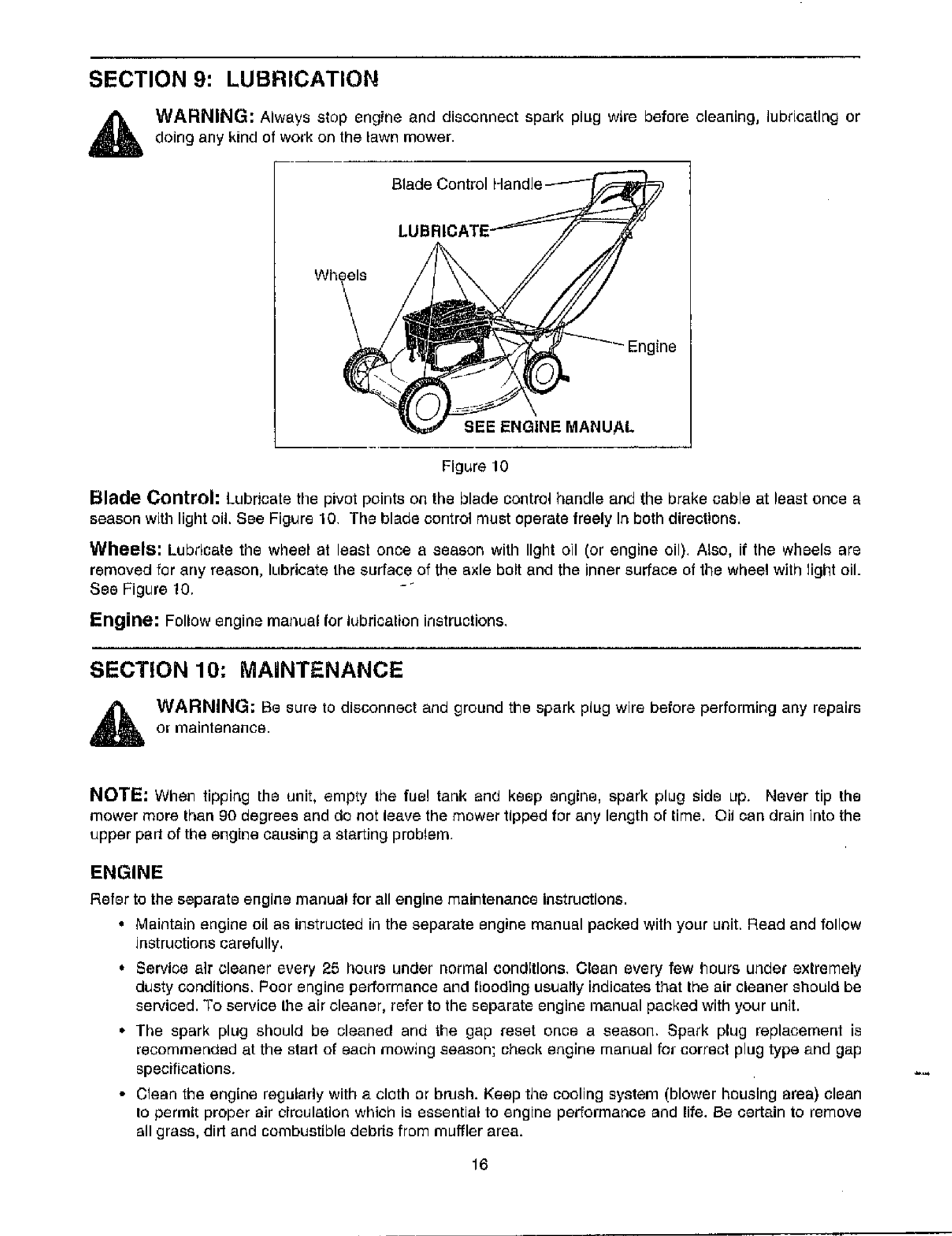
SECTION 9: LUBRICATION
WARNING: Always stop engine and disconnect spark plug wire before cleaning, lubbcatlng or
doing any kind of work on the lawn mower.
Blade Control Handle
LUBI
Wheels
Engine
BEE ENGINE MANUAL
Figure 10
Blade Control: Lubricate the pivot points on the blade control handle and the brake cable at beast once a
season with light oil. See Figure 10 The blade control must operate freely In both directions.
Wheels: Lubdcate the wheel at least once a season with light oil (or engine oil), Also, if the wheels are
removed for any reason, lubricate the surface of the axle bolt and the inner surface of the wheel with Ught oil.
See Figure 10. -_
Engine: Follow engine rna_ual for lubricalion instructions,
SECTION 10: MAINTENANCE
WARNING; Be sure to disconnect and ground the spark plug wire before performing any repairs
o[ maintenance.
NOTE: When tipping the unit, empty Ihe fue! tank and keep engine, spark plug side up. Never tip the
mower more than 90 degrees and do not leave the mower tipped for any length of time. Oil can drain into the
upper pad of the engine causing a starting problem
ENGINE
Refer to the separate engine manual for all engine maintenance instructions.
• Maintain engine oil as iJqstructed in the separate engine manual packed with your unit. Read and follow
instructions carefully,
•Service air cleaner every 25 hours ullder norl'nal (3ondltlon$. Clean every few hours u_bel" extremely
dusty conditions. Poor engine performance and flooding usually indicates that the air cleaner should be
serviced. "Toservice the air cleaner, refer to the separate engine raanual p_cked with your unit.
•Ihe spark plug should be cleaned and the gap reset once a season. Spark plug replacement is
recommerldsd at the start of each mowlng season; check etlgine manual for correct plug type and gap
specifications.
• Clean the engine regularly with a cloth or brush. Keep the cooling system (blower housing area) clean
to permit proper air droulatlon which is essential to engine pertormanee and life. Be certain to remove
_11grass, did and combustible debds from muffler area.
16
DECK
The underside of the mower deck should be cleaned after each use to prevent a buildup of grass clippings,
leaves, dirt or other matter. If this debds Is allowed to accumulate, it will invite rust and corrosion, and may
prevent proper mulching, dlecharge or bagging.
The deck may be cleaned by tilting the mower and scraping clear_ with asuitable tool (make certain the spark
plug wire Is drsconnected).
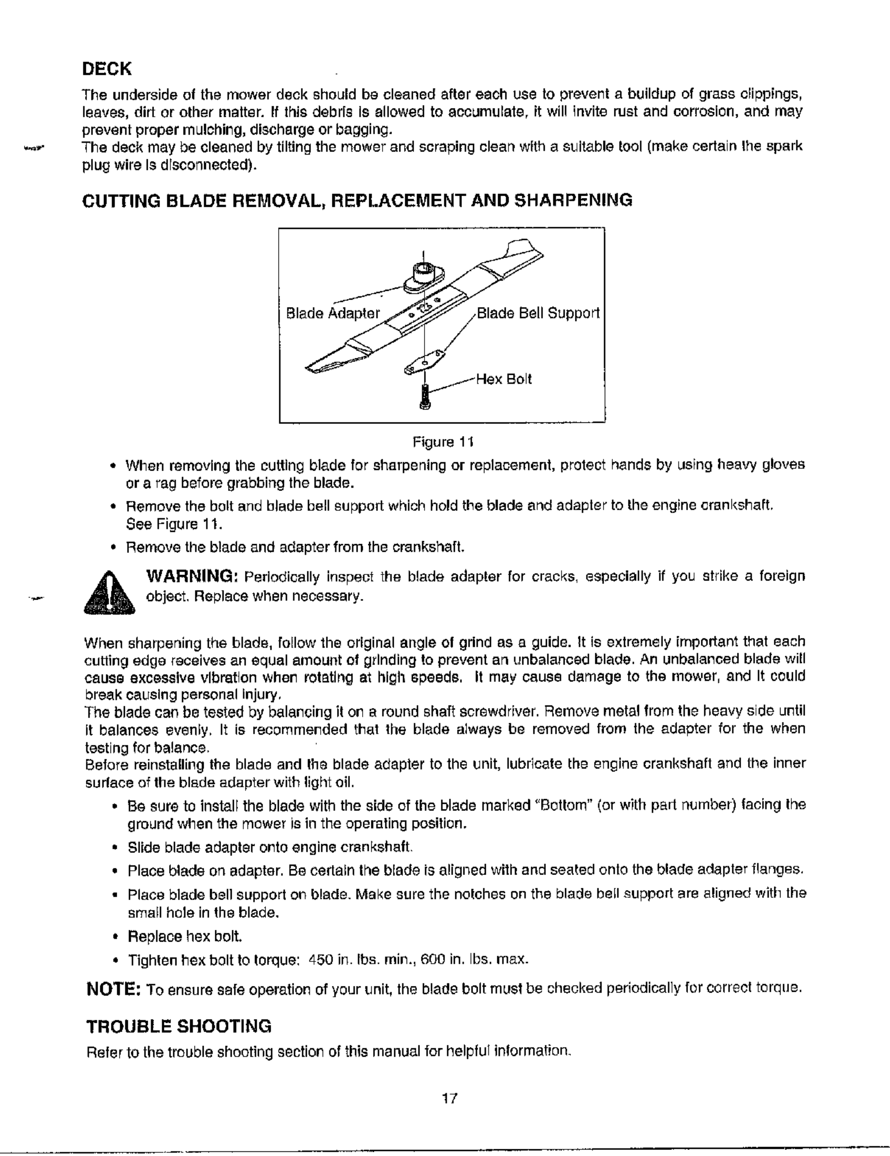
CUTTING BLADE REMOVAL, REPLACEMENT AND SHARPENING
Blade Adapter Blade Bell Support
× Bolt
Figure 11
• When removing the cutting blade for sharpening or replacement, protect hands by using heavy gloves
or arag before grabbing the blade.
• Remove the bolt and blade bell support which hold the blade and adapter to the engine crankshaft,
See Figure lt.
• Remove the blade and adapter from the crankshaft.
WARNING; Periodically inspect the blade adapter for cracks, especially if you strike a foreign
object. Replace when necessary.
When sharpening the blade, follow the original angle of gdnd as a guide, g is extremely important that each
curling edge receives an equal amoul}t of gdnding to prevent an unbalanced blade. An unbalanced blade will
cause excessive vibration when rotating at high speeds. It may cause damage to the mower, and It could
break causing personal injury,
The blade can be tested by balancing it on e round shaft screwdriver. Remove metal from the heavy side until
it balances evenly, It is recommended that the blade always be removed from the adapter for the when
testing for balance.
Before reinstalling the blade and the blade adapter to the unit, lubricate the engine crankshaft and the inner
sudace of the blade adapter with light oil.
•Be sure to install the blade with the side of the blade marked "Bottom" (or with part number) facing the
ground when the mower is in the operating position.
•Slide blade adapter onto engine crankshaft
• Place blade on adapter. Becertalnthebladeisalignedwithandseatedonththebladeadapterflanges.
• Place blade bell support or_ blade. Make sure the notches on the blade bell support are aligned with the
small here in the blade,
• Replace hex bolt.
• Tighten hex bolt to thrque: 450 in. Ibs. rain., 600 in. Ibs. max.
NOTE: To ensure safe operation of your unit, the blade bolt must be checked pedodical]y for correct torque.
TROUBLE SHOOTING
Refer to the trouble shooting section of this manual for helpful inlormagon.
17
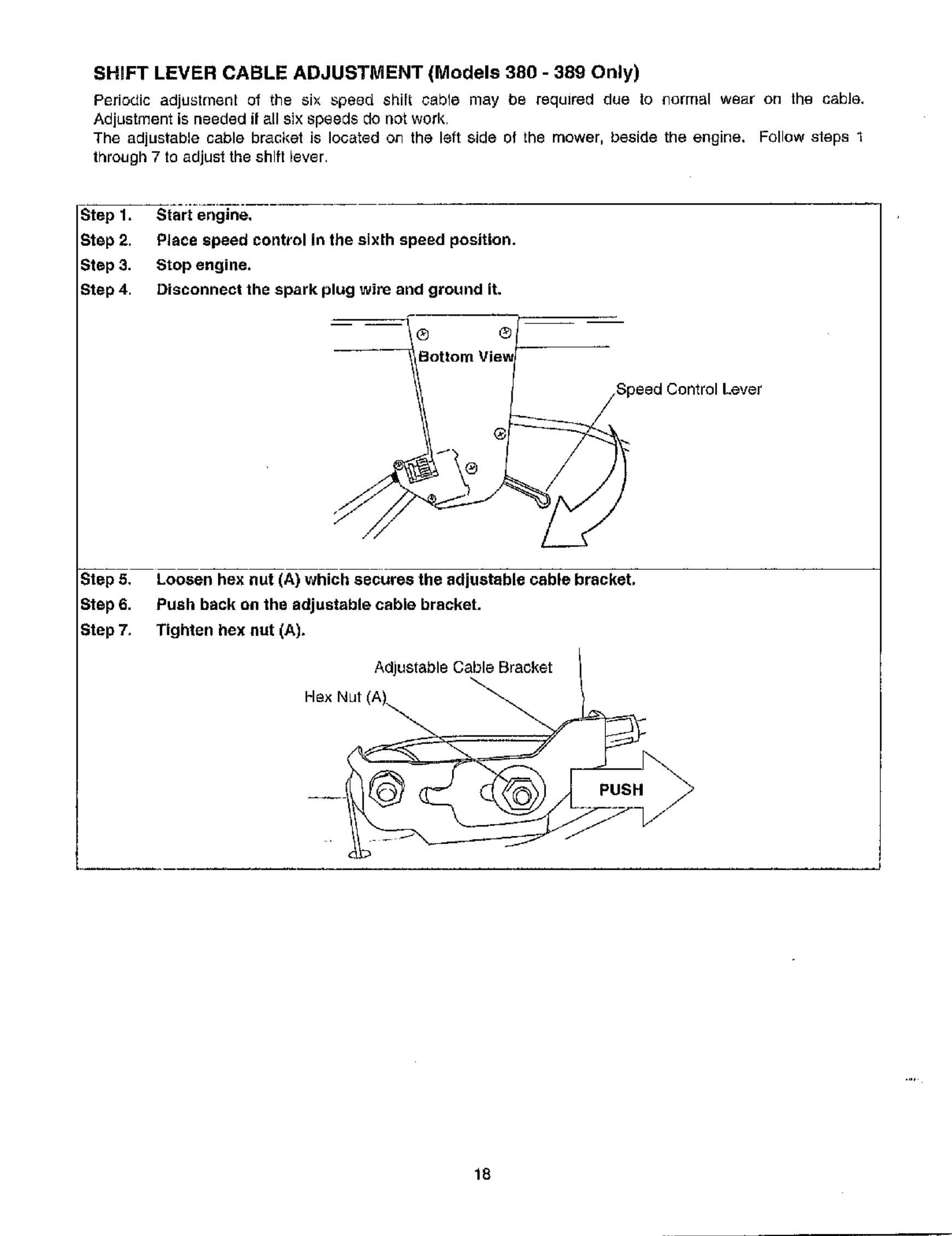
SHIFT LEVER CABLE ADJUSTMENT (Models 380 -389 Only)
Periodic adjustment of the six speod shilt cable may be required due to normal wear on the cable.
Adjustment is needed il all six speeds do not work
The adjustable cable bracket is located on the left side of the mower, beside the engine. Follow steps 1
through 7to adjust the shift lever.
Step 1, Start engine.
Step 2. Place speed control in the sixth speed position.
Step 3. Stop engine.
Step 4, Disconnect the spark plug wire and ground it.
_Speed Control Lever
Step 5, Loosen hex nut (A) which secures the adjustable cable bracket,
Step 6, Push back on the adjustable cable bracket.
Step 7. Tighten hex nut (A),
Adjustable Cable Bracket
Hex Nut (A)_
18
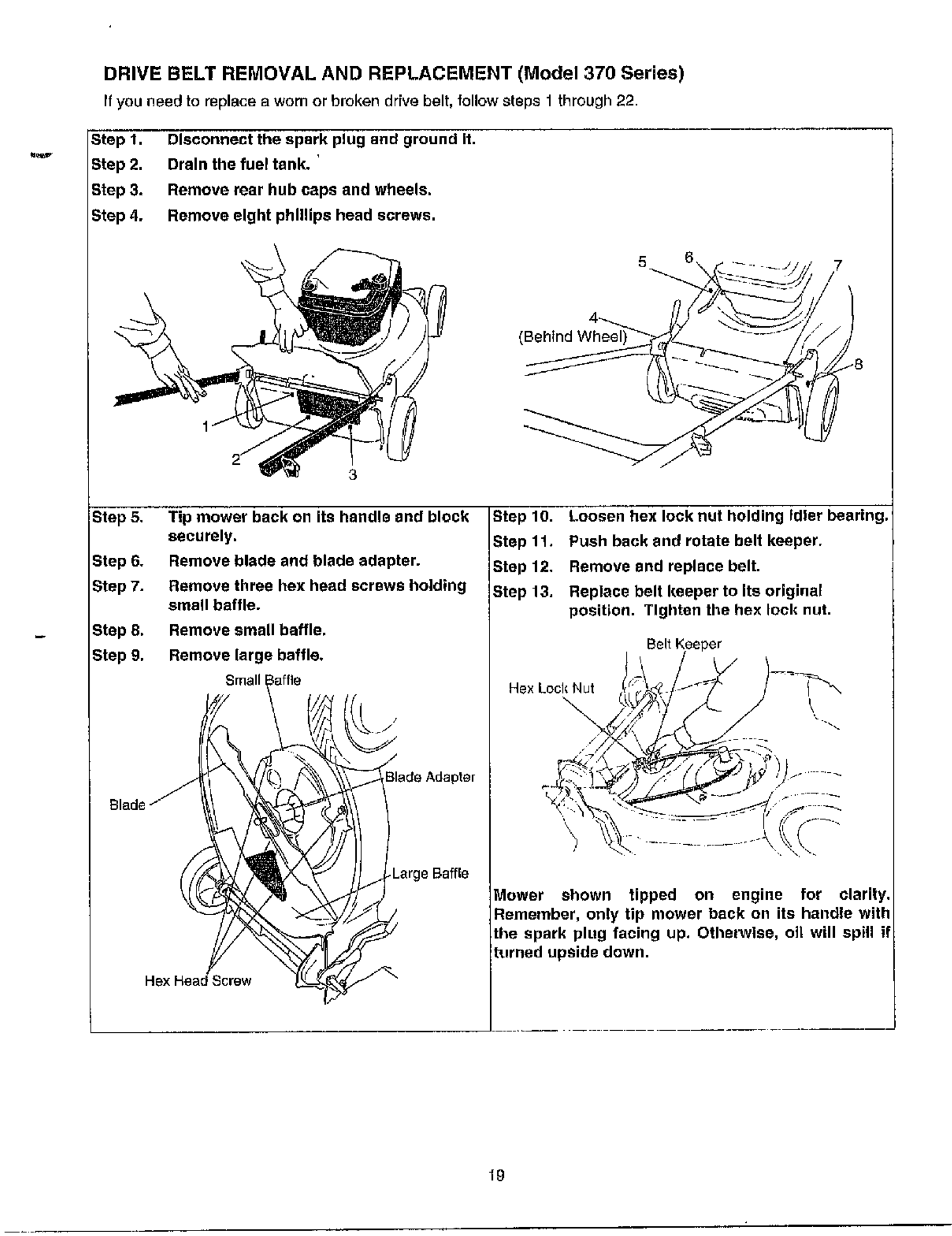
DRIVE BELT REMOVAL AND REPLACEMENT (Model 370 Series)
If you need to replace a worn or broken drive belt, follow steps 1 through22.
Step 1,
Step 2,
Step 3.
Step 4.
Disconnect the spark plug and ground it.
Drain the fuel tank. '
Remove rear hub caps and wheels.
Remove eight phillips head screws,
(Behind Wheel
/7
_tep 5,
gtep 6.
Step 7.
Step 8.
Step g.
Blade _"
Tip mower back on its handle and block
securely.
Remove blade and blade adapter.
Remove three hex head screws holding
smag baffle.
Remove small baffle,
Remove large baffle,
Small
Large Baffle
Hex Head Screw
Step 10. Loosen hex lock nut holding Fdler bearing.
Step 11. Push back and rotate belt keeper.
Step 12, Remove and replace belt.
Step 13. Replace belt Imeper to Its original
position. Tighten the hex lock nut.
Belt Keeper
Hex Lock Nut
Mower shown !ipped on engine for clari!y,
Remember, only bp mower back on ds handle wdh
the spark plug facing up. Othet_vlse, oil will spill il
turned upside down.
19
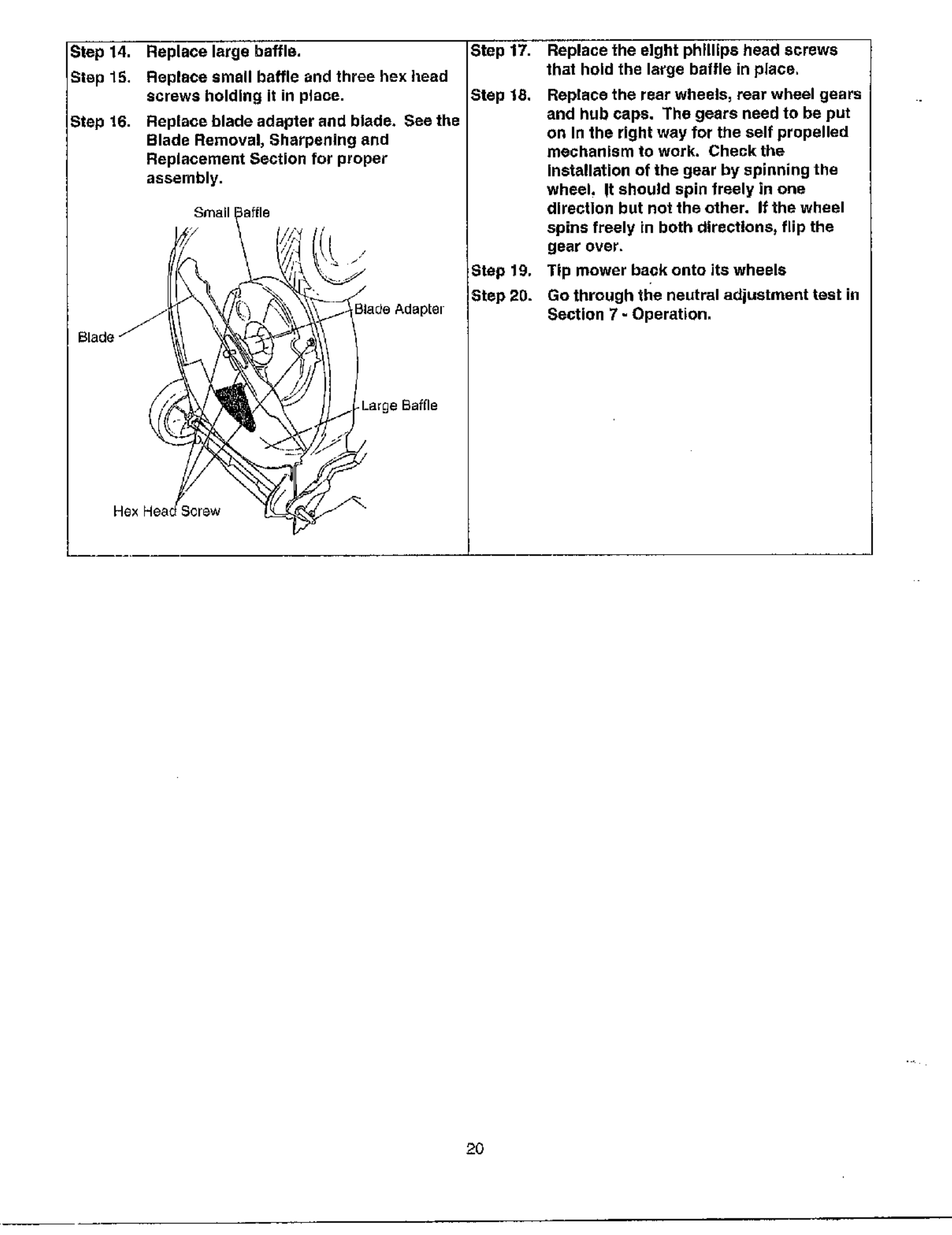
Step 14. Replace large baffle.
Step 15. Replace small baffle and three hex head
screws holding It in place.
Step 16. Replace blade adapter and blade. See the
Blade Removal, Sharpening and
Replacement Section for proper
assembly.
Small
Bla_e AdapLe_
Large Safge
Step 17. Replace the eight phillips head screws
that hold the large baffle in place,
Step iS, Replace the rear wheels, rear wheel gears
and hub caps. The gears need to be put
on In the right way for the self propelled
mechanism to work. Check the
Installation of the gear by spinning the
wheel, It should spin freely in one
direction but not the other. If the wheel
spins freely in both directions, flip the
gear over.
Step 19. Tip mower back onto its wheels
Step 20. Go through the neutral adjustment test in
Section 7 - Operation,
2O

DRIVE BELT REMOVAL AND REPLACEMENT (Model 380 Series)
you r_aed Oreplacea worn or brokendrive belt, follow steps 1 though 30.
Step 1. Disconnect the spark plug and ground it.
Step g, Drain the fuel tank,
Step 3, Remove rear hub caps and wheels.
Step 4. Remove eight phillips head screws.
Step 5. Tip mower back on its handle end block
securely.
Step 6. Remove blade and blade adapter.
Step 7. Remove three hex head screws holding
small baffle.
Step g, Remove small baffle.
Step g. Remove large baffle.
Small
Large Baffle
(Behind W _"_"
8
_p 10. Loosen hex lock nut holding idler bearin
Step 11. Using a pair of pliers, pull back and
belt keeper bracket from the slot on idler
pulley.
Step 12, Slide the belt out from between the Belt
Keeper Bracket and the idler pulley.
Transmissiofl
Pulley
Belt_
Bracket
Idler Pulle_
Bracket
Idler Pulley
Bolt and /
Locknut
21
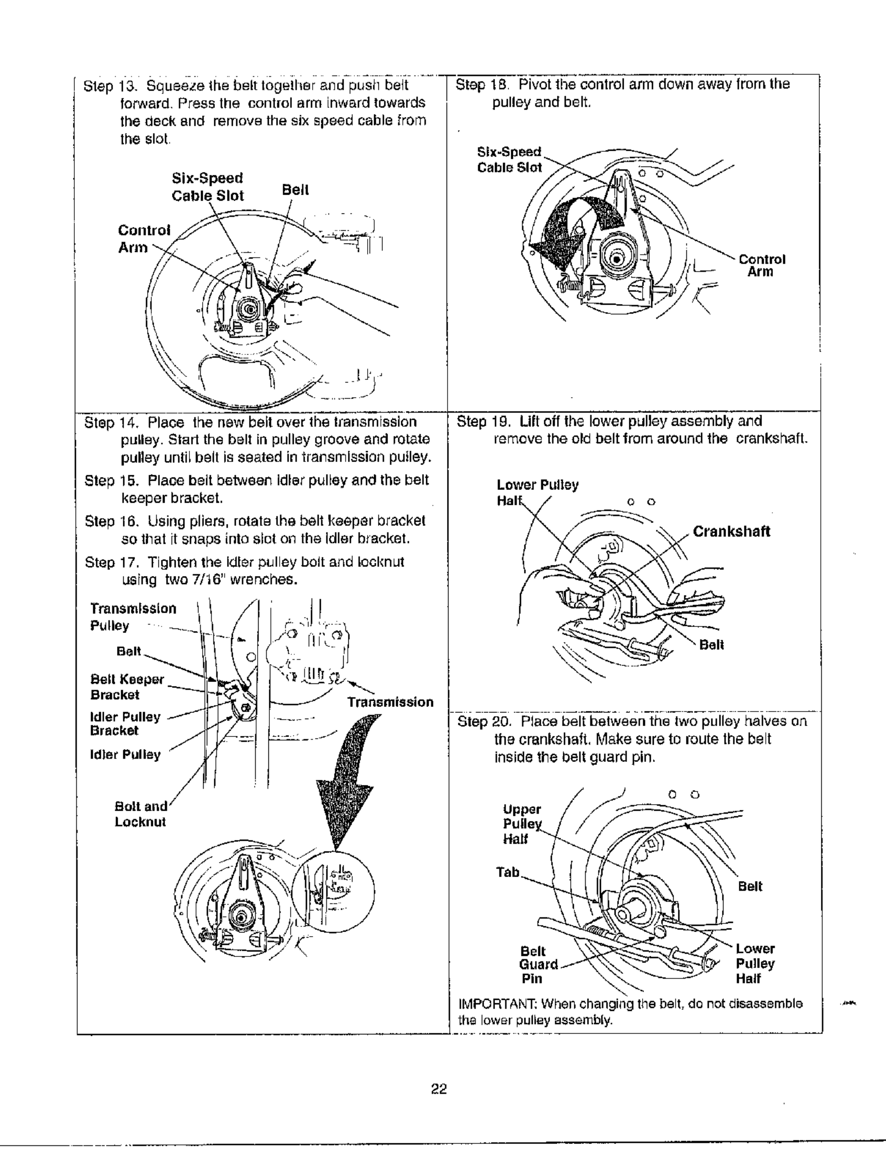
Step 13. squeeze the 5elt togeiliei a_d-push belt ..... St_,p 1g--Pivot tb_control arm down away from the
fon_vard Press the control arm inward towards
the deck and remove the six speed cable from
the slot
Six-Speed
Cable Slot Belt
COlltroJ
Step 14, Place the new belt over the Iransmission
pullBy. Start the belt in pulley groove and rotate
pulley until belt is seated in transmission puiley.
Step 15. Place beg between Idler pulley and the belt
keeper bracket.
Step 16, Using pliers, rotate the belt keeper bracket
so that it snaps into slut eL7the idler bracket.
Step 17. Tighten the Idler pulley bolt and Ioeknut
using two 7/16" wrenches.
Transmlss{on
Pulley
Belt_
Beg Keeper
Bracket
Idler Pulle_,
Bracket
Transmission
Bert =
Locknut
pulley and belt,
Control
Arm
Step 19. Lift off the lower pulley assembly and
remove the old belt from around the crankshaft.
Lower Pultey
e o
• Crankshaft
Step 20, Place belt between the two pulley halves on
the crankshaft, Make sure to route the belt
inside the belt guard pin.
O o
Upper
Pulley_
Hatf
Tab_.._ Belt
Belt
Pulley
Pin Half
IMPORTANT: When changing the belt, do not disassemble
the lower pulley assembly.
22
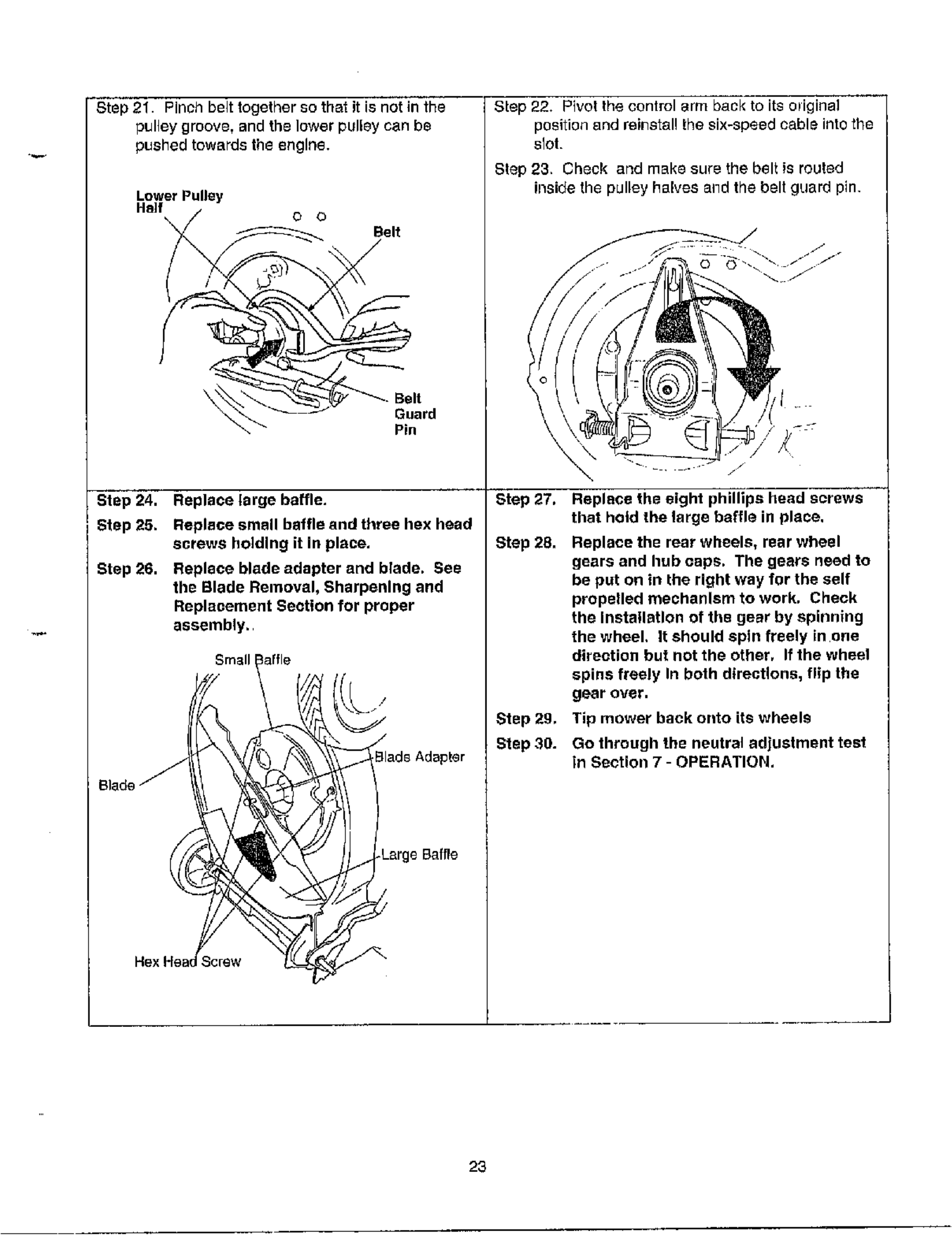
Step 21. Pinch belt together so that it is not in the
pulley groove, and the lower pulley can be
pushed towards the engine.
Lower Pulley
Ha]f 0 0
_ _ _ Guard
_'_" Pin
Step 24. Replace[arge baffle.
Step 25. Replace small baffle and three hex head
screws holding din place.
Step 26. Replace blade adapter and blade. See
the Blade Removal, Sharpening and
Replacement Section for proper
assembly.
Small affle
S.
Hex H
Step 22. Pivol the control arm back to its original
position and reilqstal! the six-speed cable into the
slot.
Step 23. Check and make sure the bal_ is routed
inside the pulley halves alld the belt guard pin.
Step 27.
Step 28.
Step 2g.
Step 30.
Replace the eight phillips head screws
that hold the large baffle in place.
Replace the rear wheels, rear wheel
gears and hub caps. The gears need to
be put on in the right way for the self
propelled mechanism to work. Check
the Installation of the gear by spinning
the wheel. It should spin freely in one
direction but not the other. If the wheel
spins freely In both directions, flip the
gear over.
Tip mower back onto its wheels
Go through the neutral adjustment test
in Section 7 - OPERATION.
23
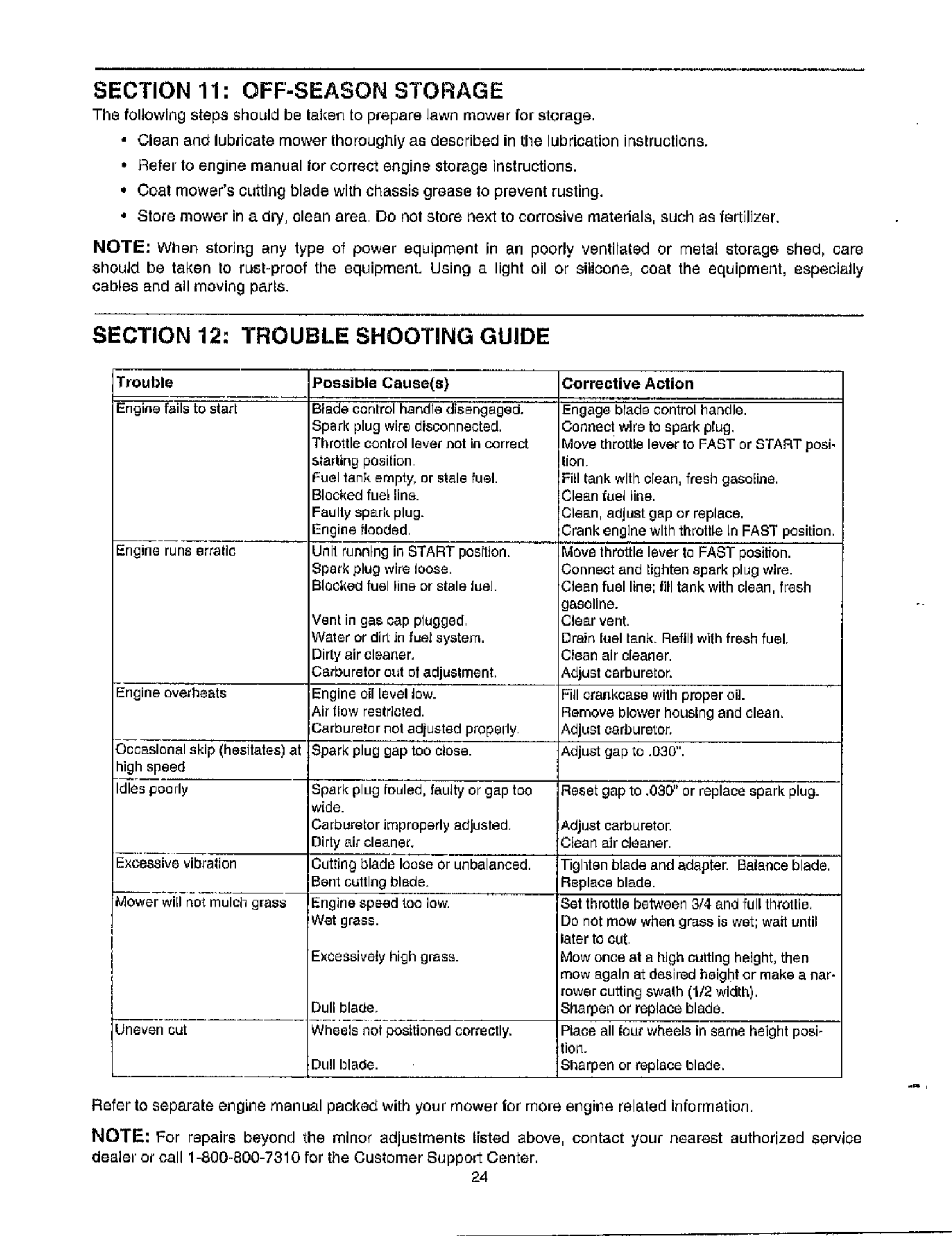
SECTION 11: OFF-SEASON STORAGE
The following steps should be taken to prepare lawn mower ='or storage.
• Clean and lubricate mower thoroughly as described in the lubrlcagon ir_structlons.
•Refel to engine manual lot correct engifl@ storage instructions.
* Coat mower's cutting blade with chassis grease to prevent rusting.
• Store mower in a dl_/, clean area Do nol store next to corrosive materials, such as fertilizer,
NOTE; When storing any type of power equipment in 811 poorly ventltated or metal storage shed, care
should be taken to rust-proof the equipment. Using a light oil or silicone, eo_,t the equipment, especially
cables and all moving pat_s.
SECTION 12: TROUBLE SHOOTING GUIDE
Trouble
Engine fails to stag
Engine runs er_sfls
Possible Cause(s}
Blade control handle disengaged.
Spark plug wire disconnectod.
I'brottle control level not in correct
_aritng position
:uel tanl_ empty, or stale fuel.
Blocked fuel line.
=_ulty spark plug.
=ngine itooded
Jnit running in START position.
_park plug wire loOSe.
Sleeked fuel line or stale fuel
_'ent in gas cap plugged¸
Nater or dirLin fuel system.
Sir_ air cleaner,
_rburetor out of adju_lmenb
:ngine oil level low.
kit itow rectrlcted.
=_,arburefor no1 adjusted properly¸
¸Spark plug gap too close.
Spark plug fouled, taugy or gap too
wide.
Carburetor improperly adjusted¸
Dirty air cleane_.
Cutting blade loose or unbalanced.
Bent cutting blade.
Engine speed toe low
Wet grass.
Excessively high grass.
Engine overheats
Occasional skip (hesitates) at
high speed
Idles poorly
Excessive vibration
Mower will not mulch grass
Unevenest
Dull blade
Wheels i oi positioned correctly.
Du!l blade.
Corrective Action
Engage blade control handle.
Connect wire to spark plug,
Move lhrotUe lever to FAST or START posi-
lion
Fill tank with clean, fresh gasoline.
Clean fuel line.
Clean, adjust gap er replace.
Crank engine with throttle in FAST position.
Move throttle lever fo FAST positron.
Connect and tighten spark plug wire.
Clean fuel line; fill tank with clean, fresh
gasoline.
Clear vent.
Drain fuel tank Refill with fresh fuel
Ctean air cleaner.
Adjust cerburetoc
Fill crankcase wilh proper oil.
Remove blower heusLng and dean.
Adjust oarburetoc
Adjust gap _o .O3O".
Reset gap to .o3g" or replace spark plug.
Adjust carburetor.
Clean air cleaner.
Tighton blade and adapter. Balance blade.
Replace blade.
Set throttle between 3/4 and full throttle.
De not mow when grass is wet; wait until
later to cut
Mow once at a high cutting height, then
mow again at desired height or make a nat-
rower cutting swa_h (1/2 width).
Shaq_en or replace blade.
P_ace all four wheels in same beight posi-
tion.
Sbarpen or replace blade.
Refer to separale ellgi_e manual packed with your mower for more ergkle related information,
NOTE: For repairs beyond the minor adjustments listed above, contact your nearest authorized service
dealer or call 1-800-800-7310 for the Customer Suppor_ Center.
24
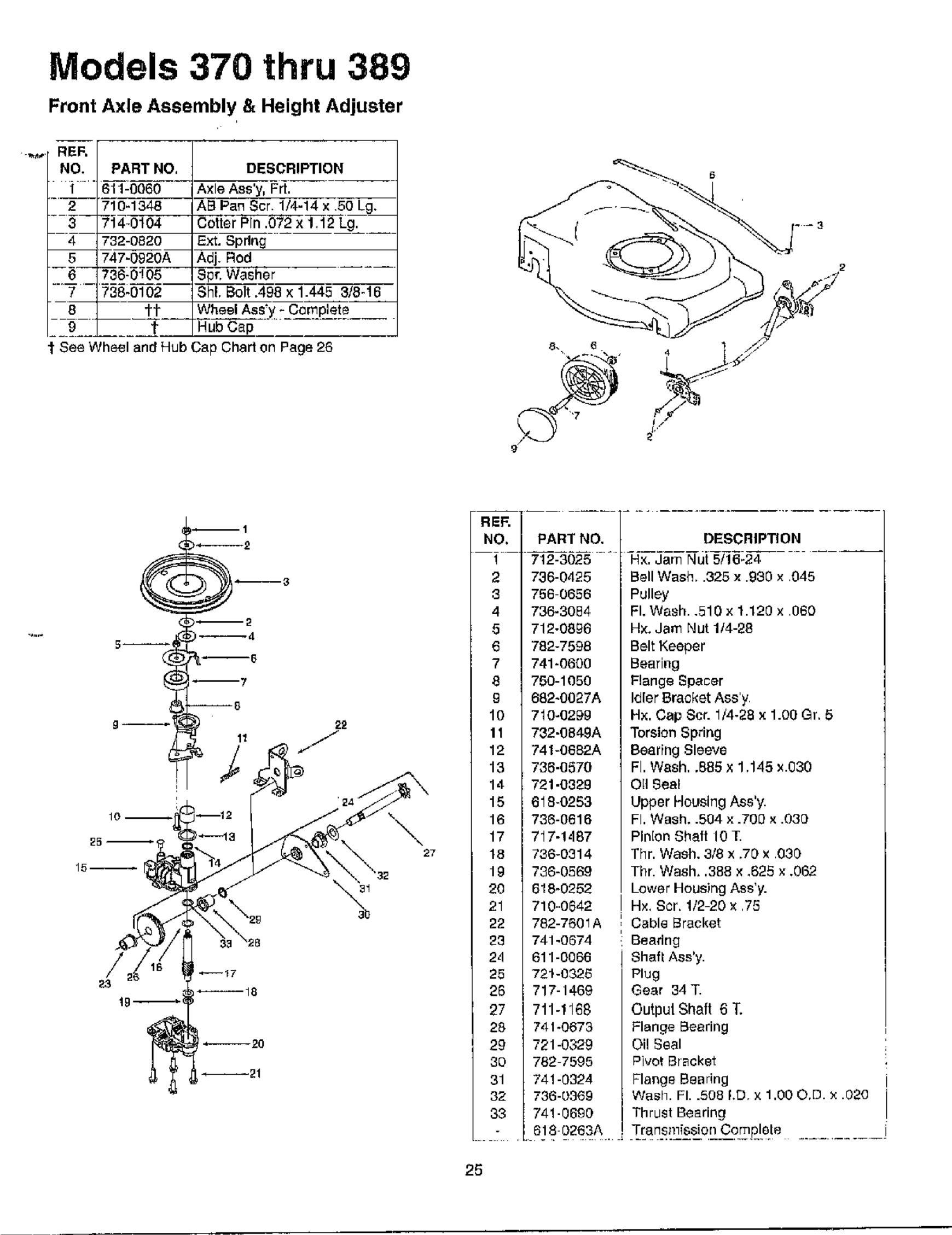
Models 370 thru 389
Front Axle Assembly & Height Adjuster
REF,
NO. PART NO,
1 611-0060
2 710-1348
3 714-0104
4732-0820
5747-0920A
6736-0!00
7 738-0102
6 __jr=
0t
DESCRIPTION
Axle Ass'y, Prt.
ASPan Sc_ 1/4-14x 50 Lg,
Cotter Pin ,072 x1,12 L0,
Ext. Spdn 0
Adj. Rod ___
Bpr, Washer
ShL Bolt .498 × 1.445 3/8-16
WheelAss" - Complete
g_-Y ..........
See Wheel and Hub Cap Chart on Page 26
10
_5
15
18
27
RE_
NO. PARTNO,
! 712_3626
2 7S0_0420
6 756 0656
4 736_36B4
S 712_0sg0
0 762-7066
7 741_0666
S 706-1656
9 6S2_0027A
16 716_626g
11 732_0B4gA
12 _41-6662A
13 235_652B
14 721_B32g
tS 018_BSS3
16 763_6_16
1_ 717_1_
16 _6-6_14
1_ _S-0_66
2g 616_6_62
_1 _10_6g4_
_ 76_-_661_
_ _41_6_
2_ 611_6_1
65 _1-6_6
_5 _17_400
g_ _tl-llg_
_6 _367_
_g _S_0_60
_ _60 _5g5
61 _4_2_
3_ _36_36_
_S _5_g3
DESCRIPTION
Hx. Jam Nut 5/16-24
Bell Wash, .325 x .030 x 045
Pulley
FI. Wash..510x 1.120 x 060
H×. Jam Nut 114-28
Belt Keeper
Bearing
Flange Spacer
Idler Bracket Ass'y
H×. Cap Scr. 1/4-28 x1.00 Gr. 5
Torsion Spring
Bearing Sleeve
FI. Wash..885 x 1,145 _.030
Oil Seal
Upper Housing Ass'y.
Pl. Wash..604 × .700 × .030
Pinion Shaft 10 T.
Thr. Wash, 3/8 x ,7g x 030
Thr. Wash. 388 x,625 ×.062
Lower Housing Ass'y.
H×, Scr. 1/2 20 x 75
Cable Bracket
Beadn 0
Shah Ass'y.
Plug
Gear 34 T.
Output Shaft 6 T.
Flange Bearing
Oi! Seal
PivotBracket
Flange Bearing
Wash. FI..508 LD x1,OOO,D. × .020
Thrust Bearing
61@ 0263A, .T[an_{llj_ssi2r!Cemp[gle ..........
29
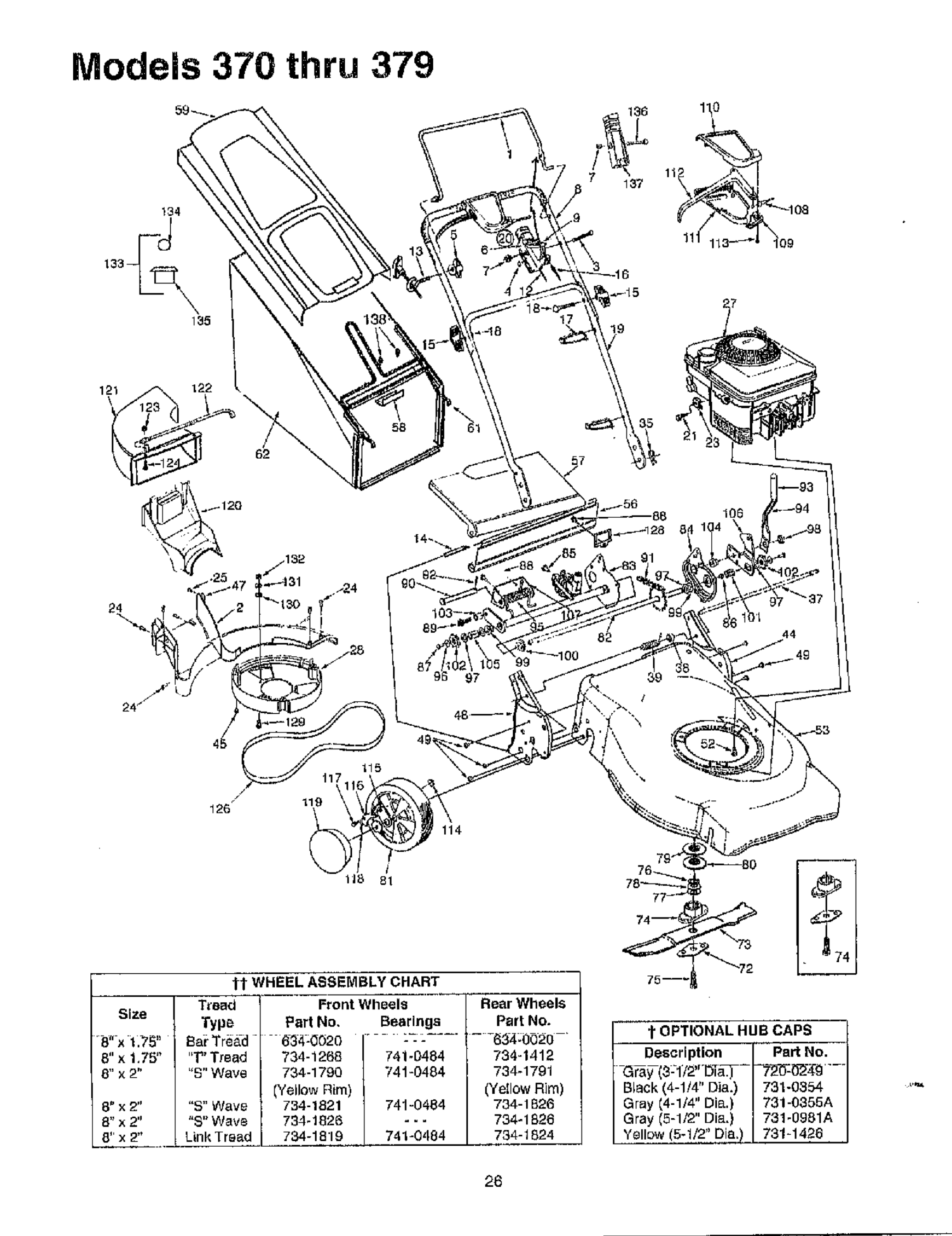
Models 370 thru 379
121
\
\
/
126
114
Size
tOPTIONAL HUB CAPS
Description Part No.
Black (4-1/4" Dia.) 731-0354
Gray 14-1/4" Dia.} 731-0355A
Gray (5-1/2" Dia,) 731-0961A
Yellow (5-1/2" Dia.) 731_1426
26
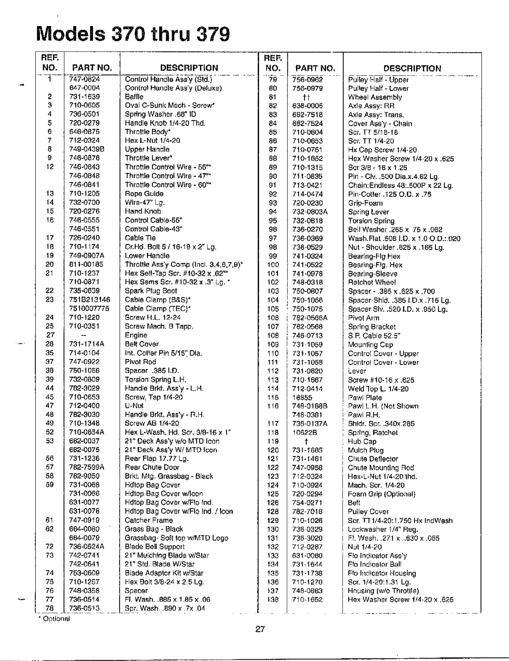
Models 370 thru 379
REF. REF.
NO. PART NO, DESCRIPTION NO. PART NO, DESCRIPTION
647=0804 Control Handle Ass'y IDelLIxe)
2 731=1630 Bagle
3 710-0600 Oval C-Sunk Math - Screw'
4796-0501 spring Washer .66" ID
5720-0279 Handle Knob 1/4-28 Thd,
6 646-0675 Throttle Body*
7 712-0324 Hex L-Nul !/4-20
6 746-04390 Upper Handle
9746-0876 Throttle Lever*
12 746-0843 Throttle Control Wire - 06"*
746-0846 Thr uttle Control Wire *47"*
746-0641 Throttle Control Wire * 60"*
13 710-1205 Rope Guide
14 732-0700 Wire-4T' L9.
15 720-0276 Hand Knob
16 746-(3555 Control Cable-65"
746-(3551 Control Cable°43"
17 726-0240 Cable _e
18 718-1174 Cr.HB Bolt0/16*18x2_Lg.
19 746-6907A Lower Handle
20 611-00165 Thretfe Ams'y Comp IIn¢l 3,4,6,7,9) +
21 710-1237 He× Self-Tap Scr. 810-38 X .69"*
710-0871 Hex SBms S_r. 810-92 x,3" Lg. *
22 735-0639 Spark Plug Beet
83 7516213146 Cable Clamp CB&S)*
7510007776 Cable Clamp (TSCI*
24 710-1220 Screw H.L. 12-24
26 710-0351 Screw Mech. B Tapp.
27 Engine
28 731-1714A Be!t Cover
35 714-0104 Int, Golfer Pitt 5/15': DIe.
37 747-0922 Pivot Rod
38 750-1065 6pacBr .365 I.D.
39 732-06(39 Torsion Spring LH,
44 782-3839 Handle Srkt. A_s'y -LI4
45 710-0653 Screw, Tap 1/4-20
47 712-0400 U-Nut
46 702-9030 Handle Brkt. Ass'y - R.H
49 710-1348 Screw AB 1/4-20
52 718-0664A Hex L-Wash. Hd. Scr. 8/8-16 x 1"
53 682-0037 21" Oeck ASB'y W/O MTS Icon
602-0075 21" Deck Ass'y W! MTG Icon
66 731-1236 Rear Flap 17.77 Lg.
67 782-7599S Rear Chute Door
68 762-9050 Srkt, I_11g, Grassbag - Slack
89 731-0068 Hdlop Bag Cover
781-6066 Hdlop Bag Cover w/Icon
691-0077 Hdlop Bag Cover w/F!e Pnd
631-0076 Hdlop Bag Cover w/Flo Ind / Icon
61 747-0919 Catcher Frame
60 664-0080 Grass Bag - Black
664-0079 Grassbag- SoIt top w/MTO Logo
72 786-0624A Brade Sell Support
73 742-0741 21" Muichfng Blade w/Star
742-0641 21" Std Blade W/Star
74 753-0608 Blade Adaptor Kll w/Star
79 710-1287 Nex Bolt 8/8.24 x25Lg
76 748-0358 Spacer
77 736-0514 FL Wash. 986 x 189 x 06
70 736-05! 3 Spr. Wash¸ 890 x :7x 04
" Optional
88
61
62
63
84
65
86
87
86
89
gO
91
02
93
94
95
96
97
98
99
100
101
102
103
104
105
106
107
10B
108
110
111
112
116
114
115
116
!17
118
119
120
121
122
123
124
125
186
128
129
130
131
132
136
134
135
+36
_37
lgB
750-0979
tt
638-0005
682-7518
682-7524
710 0604
710-0663
710-0751
710-1652
710-1315
711 0835
713 0421
714-0474
720-0230
732 0803A
732-0818
736-0270
736 0369
788 0529
741-0624
741-0522
74%0978
748-0318
17_0-0807
] 750-1056
i 750-1075
782-0566A
i 762-0568
746 0713
731 1059
731-1057
731-1058
721-0620
710 1667
718 0414
16865
749-01866
748-0391
738-0137A
10622B
t
731-168_
731-1461
747-0968
7f2-0324
710-0624
720-0294
754-0271
782-7018
710-1026
738 0329
736-3020
712 0287
631-0060
731 1644
731-1798
710-1270
748-0883
7i0-1663
Pulley Half - Lower
Wheel Assembly
Axle Assy: RR
Axle Assy: Trans,
Cover Ass'y -Chain
Scr, FT 5118-16
Scr, TT 1/4-20
Hx Cap Screw 114-20
Nex Washer Screw 1/4 20 x ,625
Scrg/B-18x125
Pin - Cir. ,500 Dia,x.4 62 Lg
Chain:Endless 48:.500P x 22 Lg.
Pin-Cotter ,125 0.[3. x .76
Grip-Foam
Spring Lever
Torsfon Spring
Bell W_sher ,285 x 75 x .062
Wash.Flat .5081.13. x 1.00 D.: 020
Nut- Shoulder ,825 x,165 Lg.
Bear[ng-FI 9 Flex
Searing FPg, Hex
Be_dng Sleeve
Ratchet Wheel
Spaoer - .385 × ,685 x .700
Spacer Shld..385 ID,x ,715 Lg,
Speeer 8Iv..520 LD, x368 Lg.
Pivot Arm
Spdng Bracket
SR Cable 525"
Mounling Cap
Centre[ Cover - Upper
COlltro_ Cove[ -Lower
Lever
Screw 8!0-16 x .625
Weld ]bp L. 1/4-20
Pawl Plate
Pawl L H (Not Shown
Pawl R,H,
Shldr. Scr..340x 285
Spring, Ratchel
Hub Cap
Mulch Plug
Chute Deflector
Chute Mour_tlng Rod
Flex-L-Nut 1/4-20 Ihd.
Maeh, Scr. !/4-20
Foam Grip (Optional)
Bett
Pulley Cever
Scr Tll/4-20:1.750 Hx IndWash
Leckwasher 1/4 _ Reg,
Ff. Wash, .271 x .830 x ,065
Nut 1/4 20
FEe Indiealor Ass'y
Fro Indlcalor Bait
Fro Ii]dicator Housing
Sor. 1/4-20:1 31 Lg.
H_using (w/o Throgle)
Hex Washer 6clew 1/4-20 x .625
27
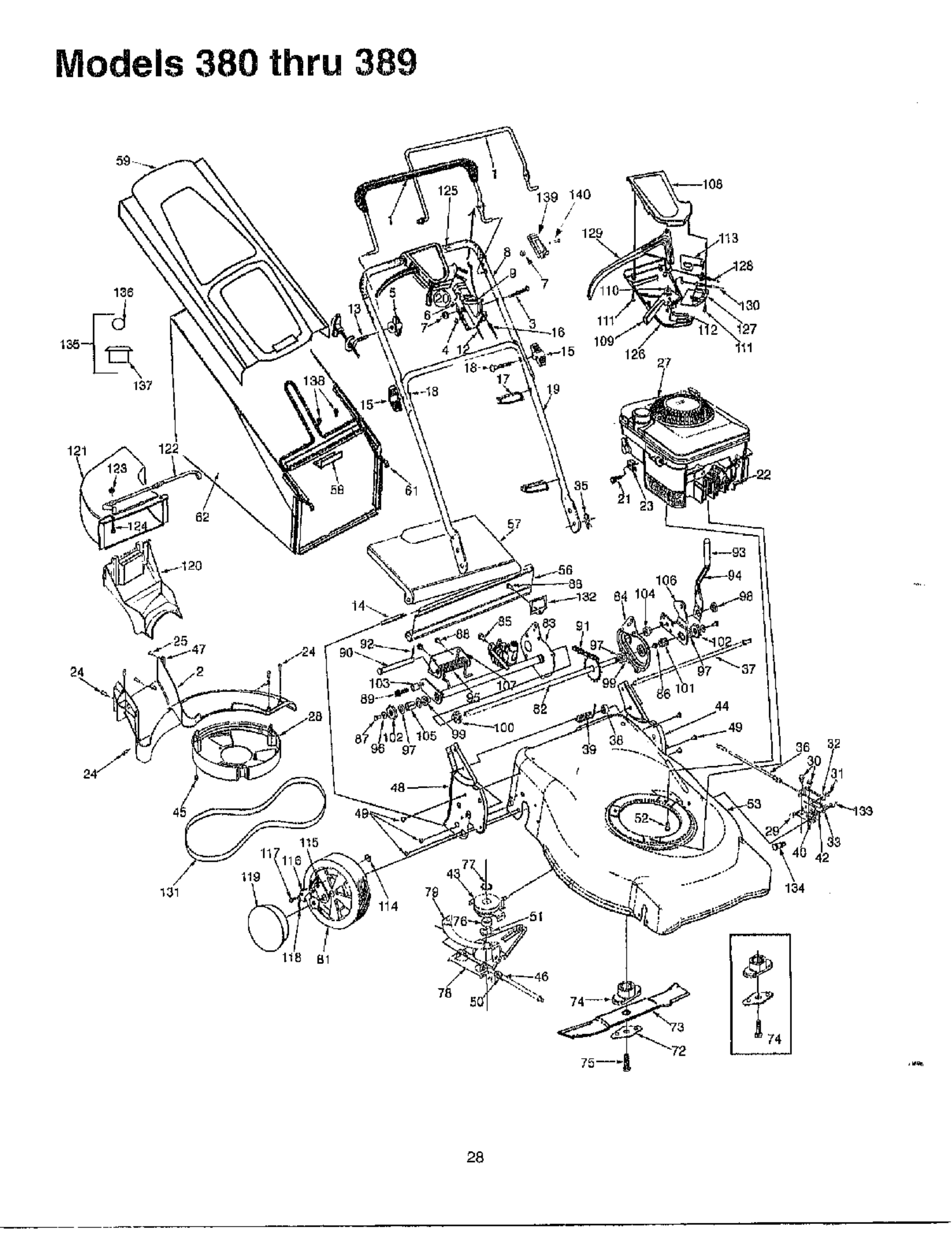
Models 380 thru 389
36
/
131 114
B1
28
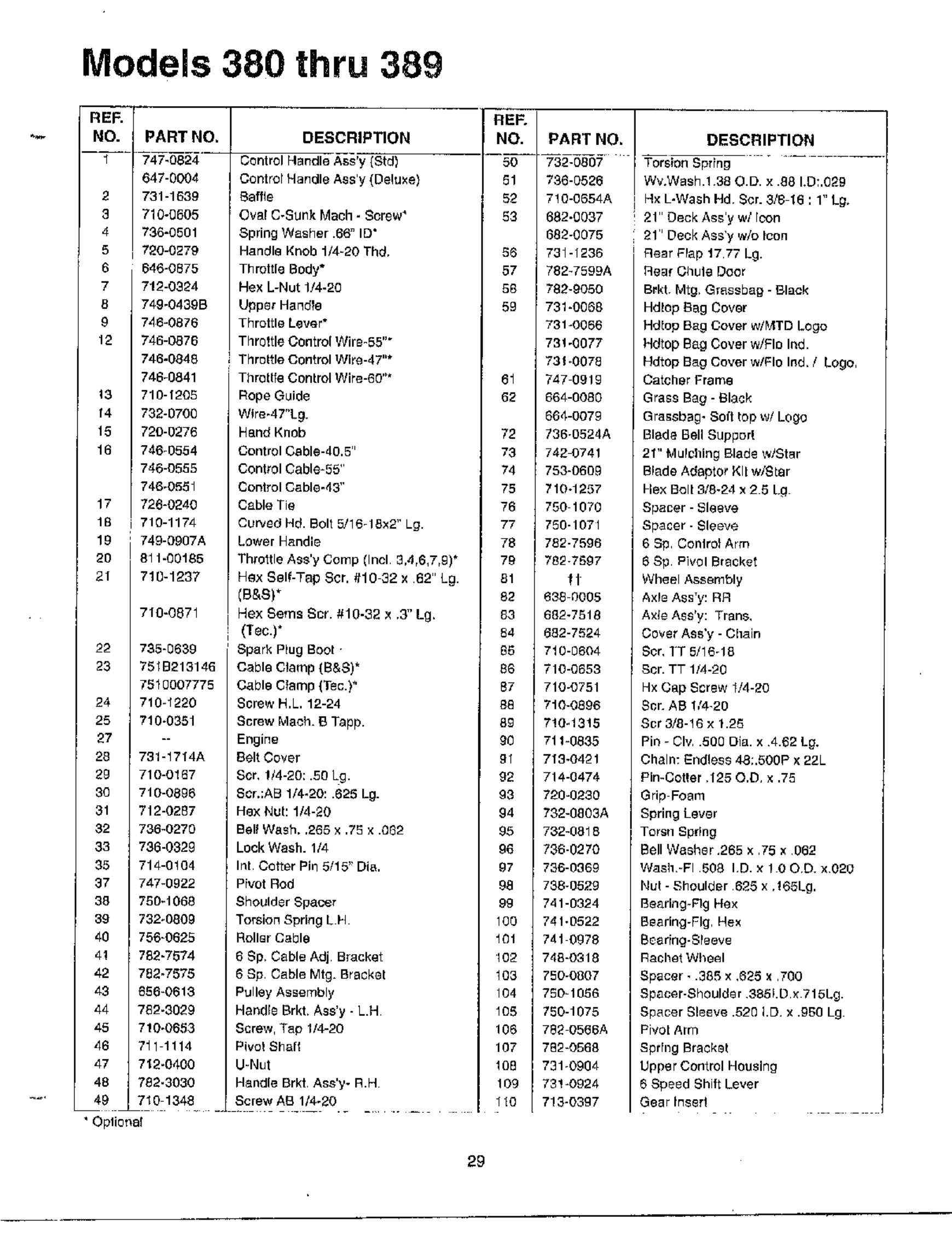
Models 380 thru 389
REF.
NO.
2
3
4
5
6
7
8
9
12
13
f4
15
16
17
16
19
20
21
22
23
24
25
27
28
83
30
31
32
33
35
37
38
39
40
41
42
43
44
45
46
47
48
49
PARTNO.
647-0004
731-1639
710-0805
736-0501
720-0279
648-0875
712-0384
749-0439B
746-0876
746-0876
746-0848
746-0841
710-f208
732-0700
720-0276
746-0554
746-0555
746-0581
726-0240
710-1174
749-0907A
811-00185
710-1237
710-0671
735-0839
7818213146
7810007775
710-_280
710-0351
781-1714A
710-0167
710-0396
712-0287
736-0270
736-0329
714-0104
747-0922
780-1068
732-0809
756-0625
788-7574
782-7575
856-0618
782-9029
710-0683
711 1114
71g-B400
788.3030
710 1348
REF.
DESCRIPTION NO.
Control Handle Ass'y CStdl 50
Contror Handle Ass'y {Deluxe) 81
Saffle 82
Ova! C-Sunk Mach- Screw* 53
Spring Washer •66=ID"
Handle Knob 1/4-20 Thd, 66
Throttle Body* 57
Hex L-Nut 1/4-20 58
Upper HandTe 59
Throttle Lever*
Throttle Control Wire-55""
', Throttle Control Wlre-4T'*
ThreSfe Control Wire-60"* 61
Rope Guide 62
Wlre-47"bg.
Hand Knob 72
Control Cable-40.5" 73
Control Cable-55' 74
Control Cable-43" 75
Cable Tie 76
Curved Hd. Bolt 5/16-18×2" Lg. 77
Lower Handle 78
Throttle Ass'y Coop (Inel 3,4,6,7,9)* 79
Hex Self-Tap Scr. 010 32 x 62" Lg. 81
(B&S)* 82
Hex Seres Scr. 010-32 × ,3" Lg. 83
(Tee.)* 84
Spark P_ug Boot 88
Cable Clamp {B&S)* 86
Cable Clamp (Tee.)* 87
Screw H.L. 12-24 86
Screw Math. B lapp. 89
Engine 98
Belt Cover gl
Son 1/4-20:.50 Lg. 92
8or,;AB 1/4-20:.626 Lg. 93
Hex Nut: 1/4-20 94
Bel! Wash..265 x .75 x .082 95
Lock Wash. 1/4 96
Int Cotter Pin 5/15" Oi_. 87
Pivot Rod 98
Shoulder Spacer 99
Torsion Spring L FI 100
Roller Cable 101
6 Sp, Cable Adj Bracket 102
8 Sp Cable Mtg. Bracket 103
Pulley Assembly 104
Handle Brkb Ass'y - L.H 105
Screw, Tap I/4-20 108
Pivot Shall 107
U-Nut 108
Handle Brkt Ass'y- B.H 109
Screw AS 1/4-20 110
•OplionsI
PART NO.
732-0807
736-0586
710-0654A
682-0037
683-0075
731-1236
782-7599A
782-9050
731-0068
731-0066
731-6077
731-0078
747 0919
664-0080
864-0079
Y36-O524A
742-0741
753-0609
?104257
750 1070
750-1071
782-7596
789-7897
fl
638 0005
682-7618
682-7824
710-0604
710-0653
710-0751
710-0896
7!0_1315
711-0835
719-0421
714-0474
720-0230
732-0803A
732-0818
736-0270
736-0669
738-0528
741-0324
741.0522
741 0978
748-0318
750-0807
780-1066
790-1075
788 0566A
782-0568
731-0904
731-0924
7!3-0397
DESCRIPTION
Tore/on Spring
Wv.Wash.1 38 O.D. x.88 LDT.Ogg
H×LWashHd $er. 3/816,1 Lg.
21" Deck Ass'y w/rcon
21' Deck Ass'y w/o Icon
Rear Brap 1777 Lg.
Sea/Ohule Door
Brkt Mtg, GrassbaB - Black
Hd_op Bag Cover
Hd_op Bag Cover w/F,_TD Logo
Hdtop Bag Cover w/BID Ind.
Hdtop Bag Cover w/FIo Ind. /Logo,
Catcher Frame
Grass Bag- Black
Gra_sbag- 8o0 top w/LOgo
Blade Bell Supper!
21" MuPchlng Blade w/Star
Blade Adaptor Nil w/SLar
Flex Bolt 9/8-24 _ 2 6 [d
Spacer - Sleeve
Spacer - Sleeve
6 Sp Conlrot Arm
6 Sp PivolBracket
Wheel Assembly
Axle Ass'y: RR
A×le Ass'y: Trans,
Cover Ass'y -Chain
Son IT 5/16-18
Scr. TT 1/4-20
Hx Cap Screw 1/4-20
Scr. AB 1/4-20
Scr 3/8-16 x 1.2_
Pin - CIv .500 Oia. x 4.82 L0.
Chain: Endless 4&.SBOP x 22L
Pin-Cotter H25 O.D, x .75
Grip Foam
Spring Lever
Torah Sp#n 6
Bell Washer,265 x 75 x 062
Wash-FI 808 ID. × ! 00D. xO20
Nut - Shoulder 828 x H65Lg,
Bearing-Fig Hex
Beadng-FIg Sex
Bearing-Sleeve
Rather Wheel
Spacer. •385 x ,886 x 760
Spacer-Shoulder 385LD _ 715L6.
Spacer Sleeve •520 I.D x .980 Lg
Pivot Arm
Sprfng Bracket
Upper Control Housing
8 Speed Shift Lever
Gear Inset!
29
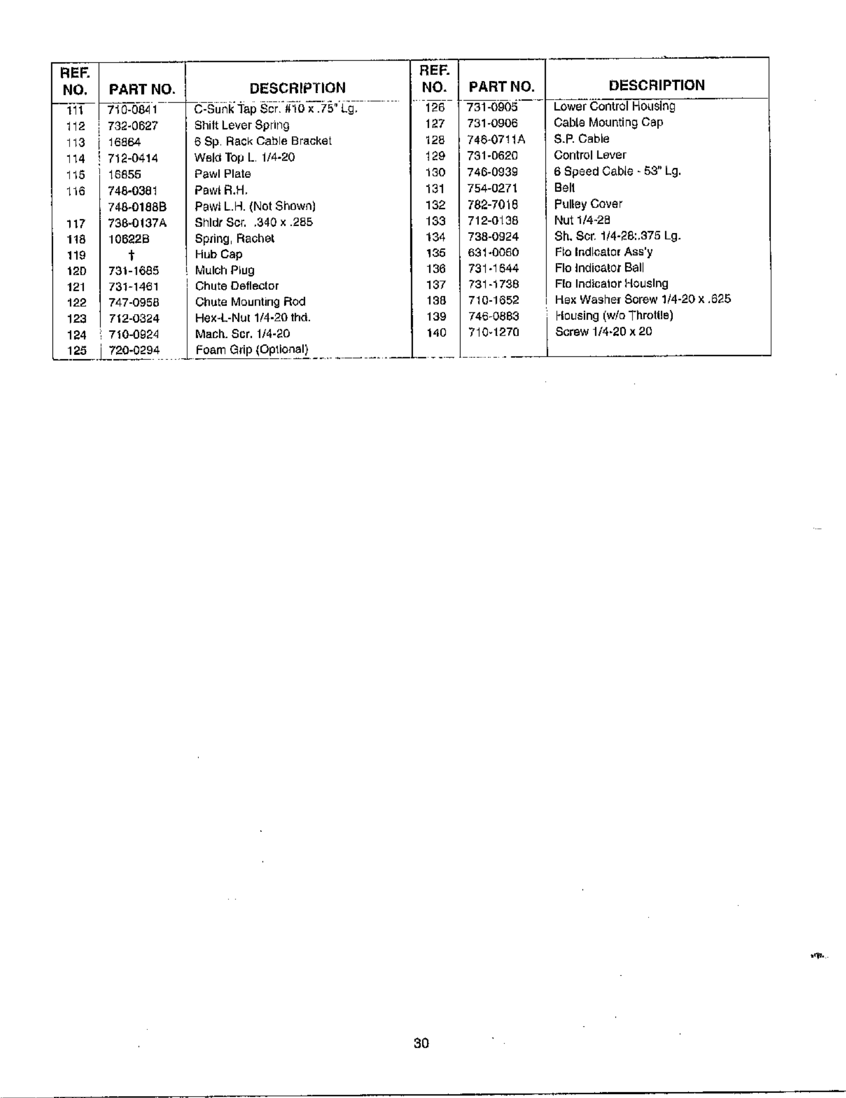
REF. 1171 REF.
NO. PART NO_ DESCRIPTION NO. PART NO.
111 1g-0841 C-SunkTapScr _!0x.75 Lg, g6 73 0905
112 732-gg27 Shilt Lever Sprirlg 127 731-0906
113 16864
114 712-0414
115 16855
_16 748-0381
748-01888
117 738-0137A
118 106228
119 f
12D 731-1885
121 731-1461
122 74710958
123 712-0324
124 i 7104)924
6 Sp Rack Cable Bracket
WBId Top [. 1/4-20
Pawl Plate
Paw_ R.H,
Pawi L.H. (Not Shown)
Shldt Scr. ,340 x •285
Spgng, Rather
Hub Cap
Mulch Plug
Chute Deflector
Chute Mounting Rod
Hex-L-Nul 1/4-20 thd.
Mach. Scr. 1/4-20
128
129
130
131
132
183
134
135
136
137
138
139
140
I746-0711A
751-062g
746-0939
754-0271
782-7018
712-0138
738-0924
631-0060
731-1844
73%1738
710-1352
746-0g83
710q270
DESCRIPTION
Cow_ _c,_tToI Housing
Cable Mounting Cap
S.E Cable
Control Lever
6 Speed Cable - 53" Lg.
Bell
PulLey Cover
Nut 1/4-28
Sh, Sot 114-28:,375 Lg.
FIg Indlc_t or Ass'y
Fig Indicator Ball
FEeIndicator Housing
Hex Washe[ Screw 1/4-20 x ,gg5
Housing (w/o Throtlle)
Screw 1/4-20 x 20
1.25 __720-0294 Foam Grip (Optional)
,r@,
30
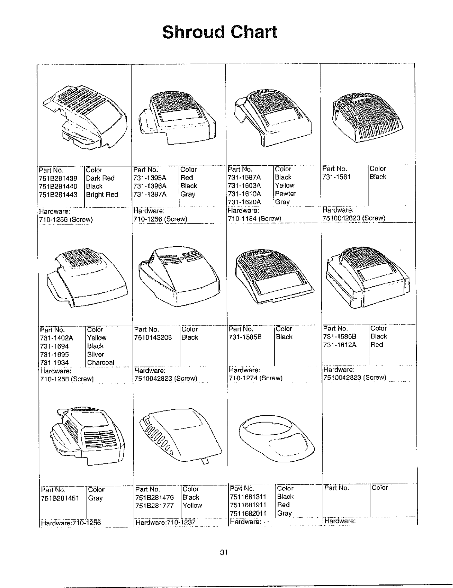
Shroud Chart
Pad NO. Part No. Er_<kC°t°r Part No, i_rP_we Part No. Color
751B281499 Dark Red 731-1395A Red 731-1587A Black 731-1061 SIack
751B28!440 _lack 731 1396A 731-1603A Yellow
751B201443 Bright Red 731-1397A !Gray 701-1610A
____ i 731-1620A =Gray ...............
HardwBre: Hardware: Hardware: Hardware;
710-1256........ Screw , i'!0-1250 (Screw) ,710 1184 (Sere_w)....... 75!0042823...... (Screw)
jJ
731-1492A Yellow H0143208 3lack 731-1585B B]ack 701-1580B 3lack
731-1694 Black ;1-1612A _ed
731-1695 Silver
731 1934 Charcoal
Hardware: ...... Hard.rare: I-iardware: Hardware:
710-1258 Screw 7510942923 (Screw) 710-1274 (Screw) 7510042823 (Screw) ......
751B281ZL51 Gray 751B281470 Black 7511681311 Black
751B281777 IYellow 7511681911 Red
7511682611 Gray
Hardware:710-1206 Hardware:710-1237 Hardware: --,Hardware:
31
MANUFACTURER'S LIMITED WARRANTY FOR:
ffAR#MACHINES
For TWO YEARS from the date of retail purchase
withil7 the United States of America, its possessions
and territories, MTD PRODUCTS INC will, al its
option, repab or replace, for the original purchaser,
free of charge, any purl er parts found to be
defective in material or workmanship. This wartan[y
covers units which have been operated and
maintained In accordance with the operating
instructions furnished with the unit, and which bare
not bead subject to misuse, abuse, commercial use,
neglect, accident, improper maintenance or
alteration
Normal wear parts or components tlqereof are
subject to separate terms as noted below in the ':No
Fault Ninety Day Consumer Warranty" cJause,
All rlormal wear part failures will be covered on this
product for a period of 90 days regardless of cause
After 90 days, but within tbe two year period, normal
wear parts failures will be covered ONLY IF caused
by defects in material or workmanship of OTHER
component parts. Normal wear parts are defined as
batteries*, belts, blades, blade adapters, grass bags,
rider deck wheels, seats, snow thrower skid shoes,
shave plates and tires
How to obtain service: Warranty service is
available, with proof of purchase, through your local
authorized service deale_. To locate the dealer in
your area, please check the yellow pages or contact
the Customer Service Depadmenl of MTD
PRODUCTS INC, P. O, Box 388022, Cleveland,
Ohio 44136-9722 Phone 1 (800) 800 7310 The
return of a complete unit will not be accepted by the
factory unless pnor written permission has been
extended by the Customer Service Department of
MTD PRODUCTS INC,
Transporter{on char£1es; Transportation charges
for the movemenl of any power equipment unit or
attachment are the responsibility of the purchaser.
Units exported out of the United States; MTD
PRODUCTS INC does not extend any warranty for
products sold or exported outside of the United
States of America, its possessions and territories,
except those sold through MTD PRODUCTS ]NC's
authorized channels of export distribution,
Other Warranties:
1, Tbe engine or component parts thereof carry
8eps.rate warranties from tbeir manLftacturef8
Please refer to the applicable manufacturer's
warranty on these items.
2. *Batteries are covered by a 90-day replacement
ws.rranty,
3. Log splitter pumps, valve£ and cylinders or
component part8 thereof are covered by a one
year warranty.
4. All ether warranties, express or implied,
including any implied warranty of merchantability
or Illness for 8, particular purpose, are hereby
expressly disclaimed in their emirety.
5. The provisions as sel forth in this warranty
provide the sole and exclusive remedy of MTD
PRODUC-FS INC's obligations arising from the
sales of its products. MTD PRODUCTS INC will
not be liable for incidental or consequential loss
or damage.
How state law relates to this warranty; This
limited warranty gives you specific legal rights, and
you may also bare other rights which vary from state
to state. Certain disclaimers are not allowed in some
states and therefore they may not apply to you
under all c#cumstances
NOTE: This warranty does not cover routine
maintenance items such as lubricants, filters, blade
sharpening and tune-ups, or adjustments such as
brake adjustments , clutch adjustments or deck
adjustments. Nor does this warranty cover normal
detedoratien of the exterior finish due to Lisa or
exposure.
