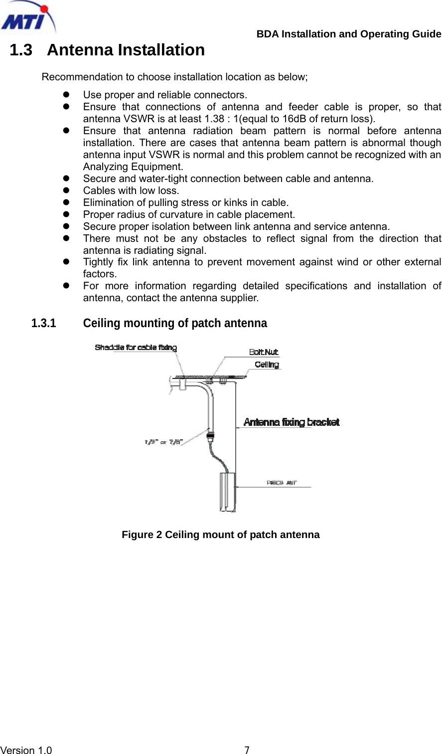
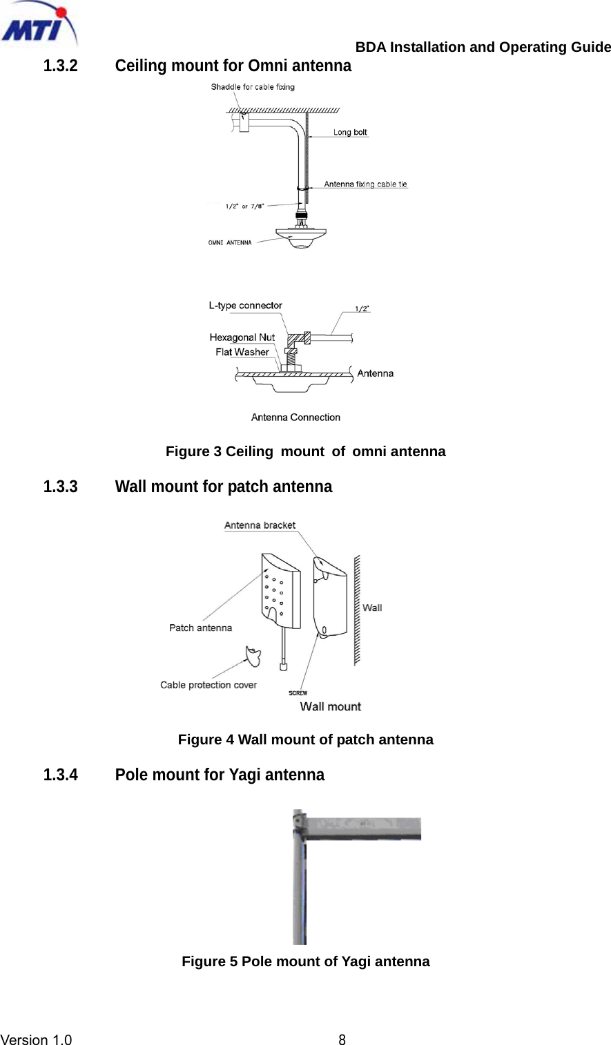
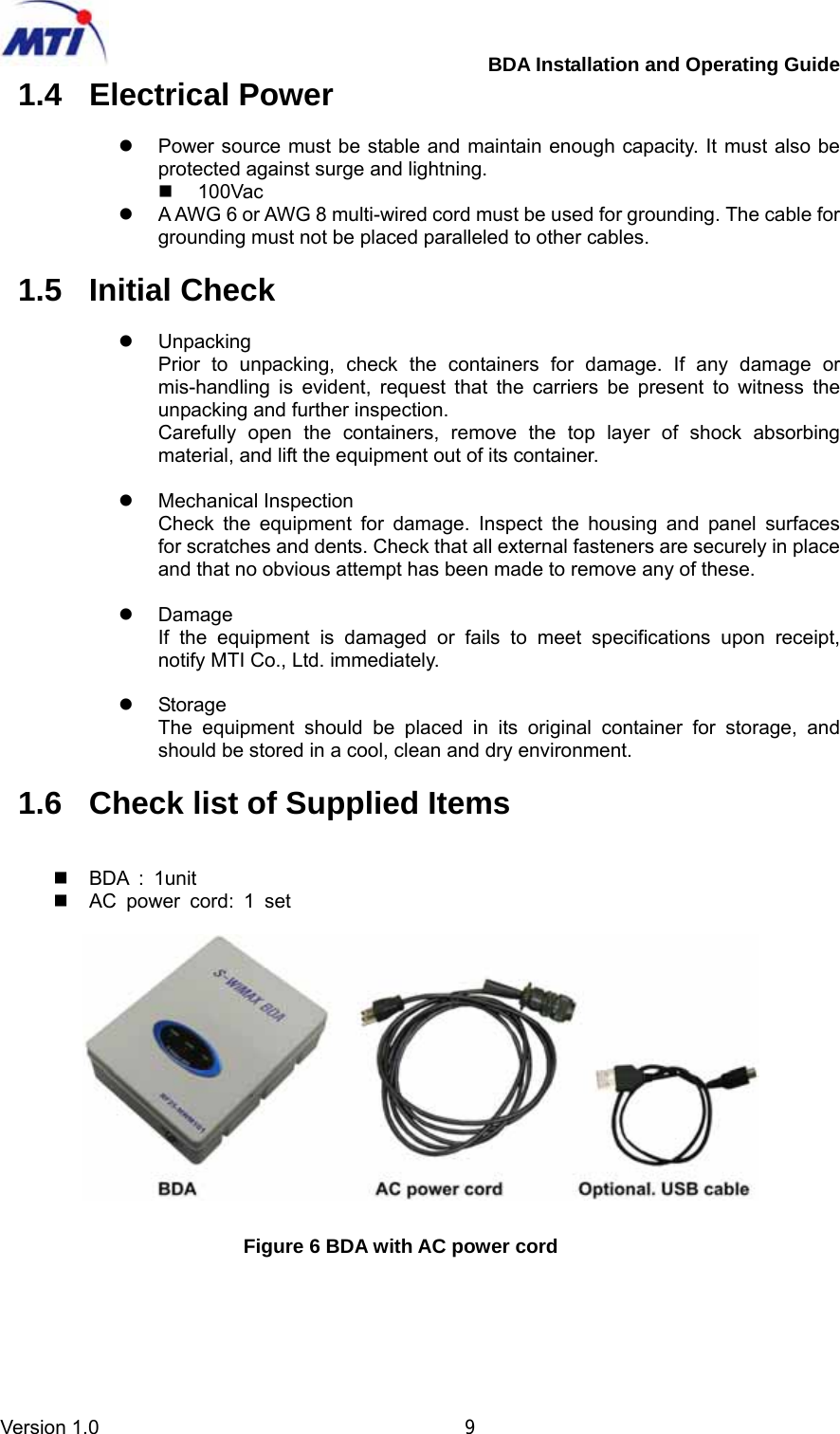
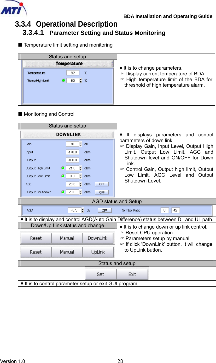
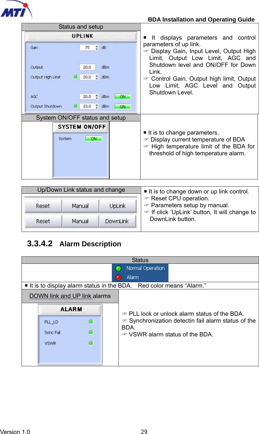
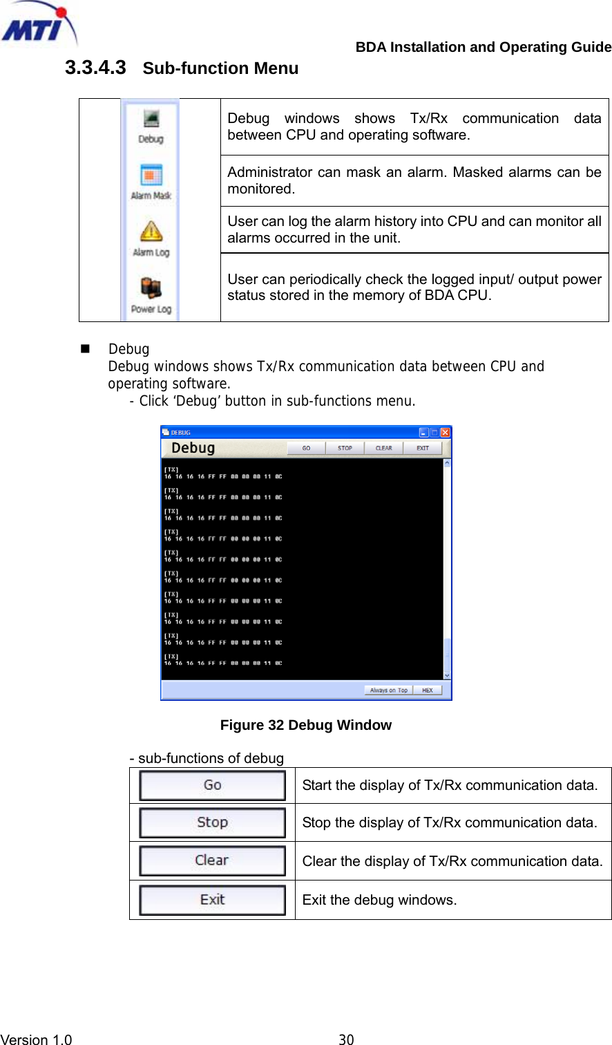
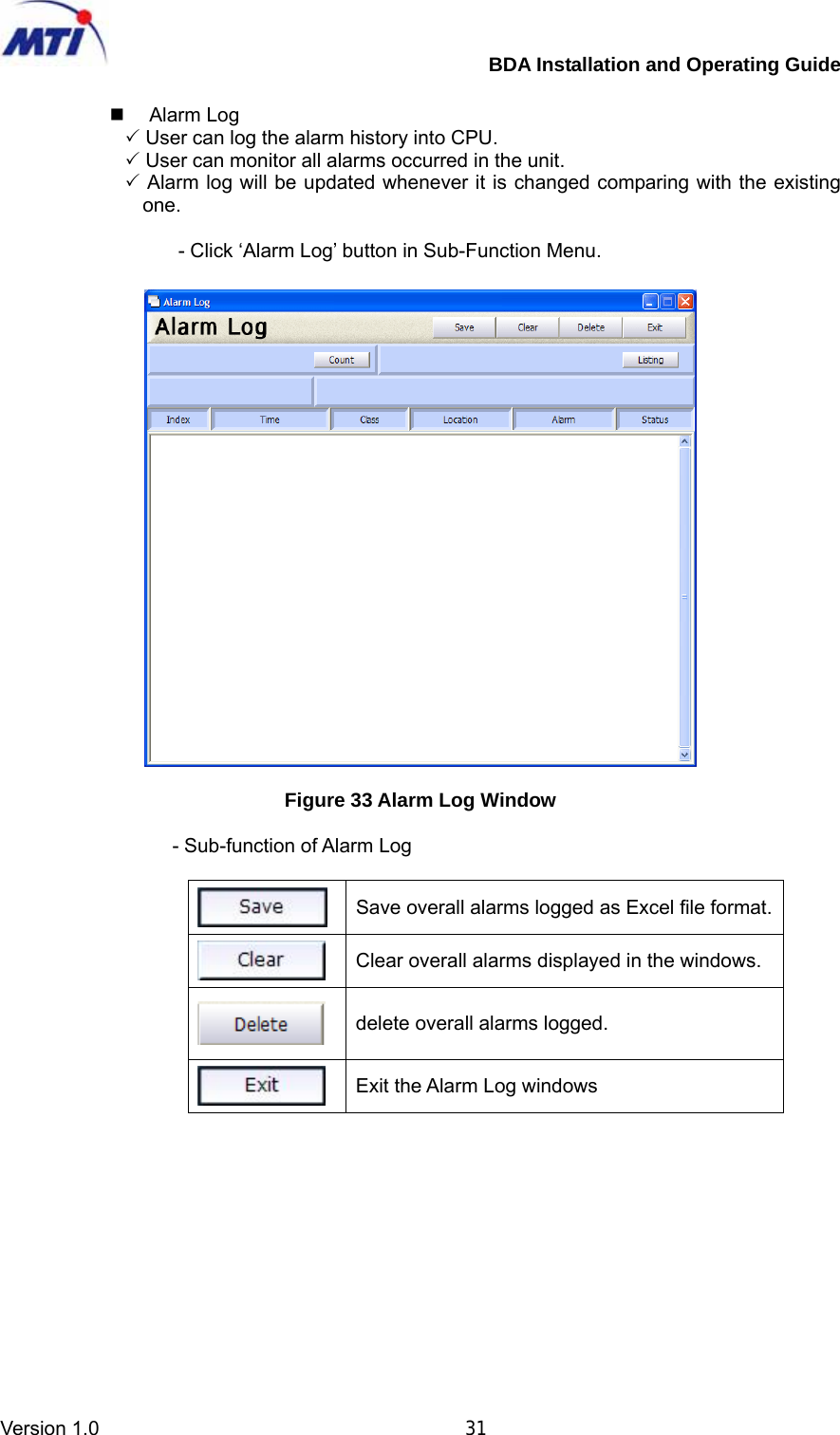
MTI RF25-MWM101 S-WiMAX BDA User Manual ATT E

MTI Co., Ltd. S-WiMAX BDA ATT E

User manual

 FCC ID : SQD-RF25-MWM101   HCT CO., LTD. SAN 136-1, AMI-RI, BUBAL-EUP, ICHEON-SI, KYOUNGKI-DO, 467-701, KOREA TEL:+82 31 639 8517    FAX:+82 31 639 8525    www.hct.co.kr Report No. : HCT-R08-186                                                                                                        1/1      ATTACHMENT E.   - USER MANUAL -
   Installation Guide +20dBm BDA for WiMAX  Standard Release V1.0      Issue Sept 16, 2008  What’s inside  Pre-installation Consideration Installation Installation Procedure Operating Software                MTI Co., Ltd.
        BDA Installation and Operating Guide Version 1.0                                       i  Publication history   Sept 2008       Issue 1. Issued for Installation Guide +20dBm BDA Release V1.0                                      ‘2008 by MTI Co., LTD                                                                                                                                 Restricted Distribution : This document contains critical information about MTI products and may not be distributed to any one written permission of MTI Co., LTD. All data and/or information contained in this document are proprietary and confidential information of MTI Co., LTD. No part of this document may be reproduced, in any form or by any means, without written permission of MTI Co., LTD.
        BDA Installation and Operating Guide Version 1.0                                       ii  Contents  1 Pre-installation Consideration ...................................................................................... 5 1.1 Introduction ...................................................................................................... 6 1.2 Site Selection ................................................................................................... 6 1.3 Antenna Installation........................................................................................... 7 1.3.1 Ceiling mounting of patch antenna ............................................................ 7 1.3.2 Ceiling mount for Omni antenna ............................................................... 8 1.3.3 Wall mount for patch antenna ................................................................... 8 1.3.4 Pole mount for Yagi antenna .................................................................... 8 1.4 Electrical Power ................................................................................................ 9 1.5 Initial Check...................................................................................................... 9 1.6 Check list of Supplied Items ............................................................................... 9 1.7 Accessories for installation of the units...............................................................10 1.7.1 Test Equipment for installation .................................................................10 1.7.2 Required Testing Equipment & Tools ........................................................10 1.8 Electrical Specification......................................................................................11 1.8.1 Specification ..........................................................................................11 1.8.2 Functions ..............................................................................................11 2 Installation ................................................................................................................12 2.1 Cable Connection to BDA .................................................................................12 2.1.1 Connection of RF cable to BDA ...............................................................12 2.1.2 Connection of electrical power cable to BDA.............................................13 2.1.3 Connection of Laptop PC to BDA.............................................................13 2.2 Cable Connection to BDA .................................................................................14 2.2.1 Connection of RF cable and electrical power cable to BDA ........................14 2.2.2 Connection of Laptop PC to BDA.............................................................15 3 Installation Procedure ................................................................................................16 3.1 Installation procedure for BDA.............................................................................16 3.1.1 Enclosure...............................................................................................16 3.1.2 Connection of electrical power cable.........................................................17 3.1.3 Installation procedure .............................................................................18 3.1.4 Connection and checking of RF output power............................................19 3.2 Installation Procedure for network........................................................................20 3.2.1 Total network configuration......................................................................20 3.2.2 Network adjustment procedure ................................................................20 3.3 Operation Software Guide...................................................................................22 3.3.1 Installation of Operating Software ............................................................22 3.3.2 Starting of Operating Software.................................................................27 3.3.3 COM Port Set-up....................................................................................27 3.3.4 Operational Description ..........................................................................28 4  Appendices. Alarm Reference List..............................................................................34
        BDA Installation and Operating Guide Version 1.0                                       iii  List of Figures  Figure 1 BDA Solution for in-building................................................................................................6 Figure 2 Ceiling mount of patch antenna..........................................................................................7 Figure 3 Ceiling  mount  of  omni antenna ........................................................................................8 Figure 4 Wall mount of patch antenna ...............................................................................................8 Figure 5 Pole mount of Yagi antenna .................................................................................................8 Figure 6 BDA with AC power cord.......................................................................................................9 Figure 7 Interfacing with Link antenna and Service antenna.....................................................12 Figure 8 Interfacing port of top side.................................................................................................12 Figure 9 Cable Connection of BDA...................................................................................................13 Figure 10 Connection of Laptop PC .................................................................................................13 Figure 11 Cable Connection of the BDA..........................................................................................14 Figure 12 Interfacing port of BDA bottom side..............................................................................14 Figure 13 Connection of Laptop PC in BDA...................................................................................15 Figure 14 Assembling of the BDA.....................................................................................................16 Figure 15 Assembly of electrical power cable of the BDA..........................................................17 Figure 16 Electrical power cable connection of the BDA ...........................................................17 Figure 18 Install bracket of the BDA on the wall ...........................................................................18 Figure 19 Cable arrangement at the BDA........................................................................................19 Figure 20 Total network configuration for indoor .........................................................................20 Figure 21 Required Items for Installation........................................................................................22 Figure 22 Installation of Operating Software (GUI).......................................................................22 Figure 23 Installation starting of Operating Software..................................................................23 Figure 24 Selection Folder of Operating Software Installation..................................................23 Figure 25 Creation of a shortcut in a start menu folder ..............................................................24 Figure 26 Setup review window.........................................................................................................24 Figure 27 Progress view of installation ...........................................................................................25 Figure 28 Installed completed............................................................................................................25 Figure 29 Display launcher Window.................................................................................................26 Figure 30 Initial window.......................................................................................................................26 Figure 31 Starting of Operating Software........................................................................................27 Figure 32 COM port set-up..................................................................................................................27 Figure 33 Debug Window ....................................................................................................................30 Figure 34 Alarm Log Window .............................................................................................................31 Figure 35 Power Log Window ............................................................................................................32 Figure 36 Alarm Mask Window...........................................................................................................32
        BDA Installation and Operating Guide Version 1.0                                       iv Abbreviation & Acronyms  AC   Alternating Current AGC    Automatic Gain Control ALC    Automatic Level Control ANT   Antenna ATTN   Attenuation or Attenuator BDA           Bi-Directional Amplifier BPF    Band Pass Filter BTS   Base Station CH, Ch   Channel CPL    Coupler or Coupling (same as Coup) Coup    Coupler or Coupling (same as CPL) CPU    Central Processing Unit (same as Controller) dB    Decibel measurement of gain and loss dBm    Decibel measurement of power, reference to 1mW D/C   Directional Coupler DNC   Down Converter DPX   Duplexer DMM   Digital Multimeter ERP    Effective Radiated Power ESD   Electrostatic Discharge EVM   Error Vector Magnitude FA   Frequency Allocation FREQ   Frequency FWD   Forward GND    Ground or Grounding GUI    Graphical User Interface HPA    High Power Linear Amplifier IF   Intermediate Frequency LED    Light Emitting Diode LNA   Low Noise Amplifier LNK   Link NMS    Network Management System PSU    Power Supply Unit REV   Reverse RF   Radio Frequency RSSI    Receive Sensitivity Strength Indication RTC   Real Time Clock RX   Receive SVC   Service TEMP   Temperature TX   Transmit VSWR    Voltage Standing Wave Ratio
        BDA Installation and Operating Guide Version 1.0                                       5  1 Pre-installation Consideration               Prepare the proper ground prior to installation of the BDA; the ground must be independent from that for other equipment (Do not use common ground with others). The ground must be connected with AWG 6 or AWG 8 multi-wired cable. The cord must not be parallel to other electrical or RF cable. Do not apply the electric power without connecting output port of BDA to Antenna or Dummy Load. The system will be stabilized in 5 minutes after power is switched on. Before operation of the BDA, ensure that RF connectors and cables are not damaged and properly connected.            DO NOT FASTEN OR UNFASTEN THE COAXIAL CABLE CONNECTOR ON THE BDA WITH UNDER THE UNIT POWERED EQUIPMENT. EXTREME CARE MUST BE TAKEN TO AVOID ELECTRIC SHOCK. MAKE SURE THAT POWER SUPPLIER IN BDA UNIT IS TURNED OFF PRIOR TO CONNECTING THE COAXIAL CABLE TO THE CABLE ENTRY CONNECTOR ON BDA ENCLOSURE. DO NOT OPEN THE DOOR OF THE UNIT WHEN IT IS IN OPERATION WITHOUT PROPER PERMISSION FROM THE AUTHORITIES. DANGEROUSLY HIGH VOLTAGES APPEAR WITHIN THE EQUIPMENT. EXTREME CARE MUST BE TAKEN TO AVOID ELECTRIC SHOCK.
        BDA Installation and Operating Guide Version 1.0                                       6 1.1 Introduction  The mobile coverage extension solution is used to extend coverage to specific areas within a building, multiple buildings, or subway. This coverage extension system solution features useful combination that distributes wireless coverage over RF cable and antennas, making the best choice for signal quality, flexibility, and overall performance. The mobile coverage extension product family offers service providers a flexible, low cost, easy installation to improve customer retention and offer enhanced services to meet increasing subscriber demands.  1.2 Site Selection  Depending on RF environment and size of space, output power of the BDA and number of antennas are decided for optimum service. For instance, an OMNI antenna (service) is connected to a small BDA for a small room, two or three OMNI antennas are con-nected to a medium BDA, or several antennas are distributed in couple of floors of a building if a large BDA is installed.   Recommendation to choose installation topology as below;   Figure 1 BDA Solution for in-building  z  Less interference from other BTS Cells z  Easy access and maintenance of the equipment   z  Avoiding direct sunlight to protect equipment z  Easy access to electrical power z  A shadow and cool environment
        BDA Installation and Operating Guide Version 1.0                                       7 1.3 Antenna Installation  Recommendation to choose installation location as below; z  Use proper and reliable connectors. z  Ensure that connections of antenna and feeder cable is proper, so that antenna VSWR is at least 1.38 : 1(equal to 16dB of return loss). z  Ensure that antenna radiation beam pattern is normal before antenna installation. There are cases that antenna beam pattern is abnormal though antenna input VSWR is normal and this problem cannot be recognized with an Analyzing Equipment. z  Secure and water-tight connection between cable and antenna. z  Cables with low loss. z  Elimination of pulling stress or kinks in cable. z  Proper radius of curvature in cable placement. z  Secure proper isolation between link antenna and service antenna. z  There must not be any obstacles to reflect signal from the direction that antenna is radiating signal. z  Tightly fix link antenna to prevent movement against wind or other external factors. z  For more information regarding detailed specifications and installation of antenna, contact the antenna supplier.  1.3.1  Ceiling mounting of patch antenna    Figure 2 Ceiling mount of patch antenna
        BDA Installation and Operating Guide Version 1.0                                       8 1.3.2  Ceiling mount for Omni antenna   Figure 3 Ceiling  mount  of  omni antenna  1.3.3  Wall mount for patch antenna    Figure 4 Wall mount of patch antenna  1.3.4  Pole mount for Yagi antenna   Figure 5 Pole mount of Yagi antenna
        BDA Installation and Operating Guide Version 1.0                                       9 1.4 Electrical Power  z  Power source must be stable and maintain enough capacity. It must also be protected against surge and lightning.  100Vac z  A AWG 6 or AWG 8 multi-wired cord must be used for grounding. The cable for grounding must not be placed paralleled to other cables.  1.5 Initial Check  z Unpacking Prior to unpacking, check the containers for damage. If any damage or mis-handling is evident, request that the carriers be present to witness the unpacking and further inspection. Carefully open the containers, remove the top layer of shock absorbing material, and lift the equipment out of its container.  z Mechanical Inspection Check the equipment for damage. Inspect the housing and panel surfaces for scratches and dents. Check that all external fasteners are securely in place and that no obvious attempt has been made to remove any of these.  z Damage If the equipment is damaged or fails to meet specifications upon receipt, notify MTI Co., Ltd. immediately.  z Storage The equipment should be placed in its original container for storage, and should be stored in a cool, clean and dry environment.  1.6  Check list of Supplied Items     BDA : 1unit   AC power cord: 1 set    Figure 6 BDA with AC power cord
        BDA Installation and Operating Guide Version 1.0                                       10 1.7  Accessories for installation of the units  z  Laptop PC : 1 unit z  USB Cable : 1 unit   z  AC Power Extender : 1 unit z  AC Power Cord for BDA    : 1 set z  RF Coaxial Cable : 3 set of RG cable for Analyzing equipment. z  Adapter; 3 units of N-male to SMA-female, 1 unit of N-female to N-female, SMA-female to SMA-female z  Other accessories to install the BDA, such as fixed attenuations (5dB, 10dB & 15dB); it depends on the situation of the site.  1.7.1  Test Equipment for installation  z WiMAX Signal Analyzer(E4445A)  z WiMAX Signal Generator(E4438C)  z VSA (Vector Signal Analyzing Software VSA89600 in PC)  z Network Analyzer  z Power Meter  z 30dB High Power Fixed Attenuator  z High Power Termination  z Digital Multimeter  z Laptop PC z RF Connection Cable Set  z 10dB/1dB Step Attenuator for 2.5GHz  z Noise Figure Meter  z Noise Figure Source   1.7.2  Required Testing Equipment & Tools  z  Spectrum Analyzer 1 set (Spectrum analyzer for CDMA, E4445A for WiMAX) z  Signal Generator 1 set (CDMA sig gen for CDMA, E4438C, VSA for WiMAX) z  Site Master 1 set (Anritsu S331A or equivalent) z  Laptop PC 1 set (Pentium-class PC, 90MHz or higher recommended, Window 95 or more recent)   z  Digital Multi-meter 1 set
        BDA Installation and Operating Guide Version 1.0                                       11 1.8 Electrical Specification  1.8.1 Specification Item  Specification  Remark Input Frequency  2642 ~ 2672MHz Output Frequency  2642 ~ 2672MHz Operating Bandwidth  30MHz Fixed FH Channel VSWR  1.5:1  DL/UL DL  -25 ~ -55dBm/Total   Input  UL MAX –55dBm/ Total  DL  45~75dB   Gain Adjustment Range  UL 45~75dB  Gain Adjustment Step  1dB Step  DL/UL Gain Adjustment Tolerance  < ±0.7dB  DL/UL DL  > 20dBm/Toltal   Max. Output  UL > 20dBm/Toltal  DL  30dB AGC  UL 30dB  DL  23dBm/Total   Shut Down  UL 23dBm/Total  Impedance (IN/OUT)  50Ω   In-Band  US FCC 04-135 & 27.53 Compliance   Spectral MaskOut-Band US FCC 04-135 & 27.53 Compliance  System Delay  < 3.0us  DL/UL ≤5dB  @ Max. Gain Noise Figure(DL/UL)  ≤12dB  @ Min. Gain Flatness  < 3dB  pk-pk @ BW 30MHzFrequency Stability  < ±0.02ppm  DL/UL EVM  <5% (DL:64QAM, UL:16QAM) Source Comparison Sync. Signal Detection level (DL) Min : -75dBm  @ BDA Input Size(mm)  190 * 250 * 80 (7.6 * 10 * 3.2 inch)   Weight  < 6 kg   Power Consumption  < 40 W @Instant Max. Power 1.8.2 Functions Item  Specification VSWR Alarm  1.5:1 Over Power Alarm  @ Max. Output +2dB AGC(Auto Gain Control)  30dB AGD(Auto Gain Difference of DL/UL)  0 ~ 10
        BDA Installation and Operating Guide Version 1.0                                       12  2 Installation  2.1  Cable Connection to BDA  2.1.1  Connection of RF cable to BDA  Input and output of BDA is fit for interface with N-type RF cable. Signal of RAS DL/UL path at antenna connection cable is fed/transmitted to/from “LINK ANT” at BDA bottom side of enclosure and amplified signal from BDA is fed/transmitted to/from “SERVICE ANT” port to service area at BDA bottom side of enclosure.(Refer to Figure 10).    z  Interfacing with link and service antenna   Figure 7 Interfacing with Link antenna and Service antenna  z  RG 400 or similar quality of coaxial cable (50ohm) is recommended for the link and service antenna connection. z  “LINK ANT” and “SERVICE ANT” antenna port of BDA is to be connected to the link and service antenna with RF cable. Refer to the above figure for the connection port at the unit.   Figure 8 Interfacing port of top side
        BDA Installation and Operating Guide Version 1.0                                       13 2.1.2  Connection of electrical power cable to BDA  AC Power (100V ± 20%) is supplied to the unit with the AC Power cable. Before connection of ground cable, don’t plug the AC power cable into the wall outlet of AC power source. Connect by using grounding cable between CHASSIS Port locating left side of the BDA and Ground bar. plug the AC power cable into the wall outlet of AC power source.            Figure 9 Cable Connection of BDA  2.1.3  Connection of Laptop PC to BDA  The BDA should be connected to a laptop PC with the USB cable to control BDA locally. Plug the USB cable from the laptop PC into the USB connector in the BDA. Refer to operating software chapter for monitoring and controlling the unit.   Figure 10 Connection of Laptop PC
        BDA Installation and Operating Guide Version 1.0                                       14  2.2  Cable Connection to BDA  2.2.1  Connection of RF cable and electrical power cable to BDA  Service antenna port is to be connected to the “SVC ANT” port of BDA with RF cable. “LINK ANT” port of BDA also connected to link antenna with 50ohm feeder. Refer to the below figure for the connection port at the unit. AC Power (100V ± 20%) is supplied to the unit with the AC Power cord. Plug the AC power cord into the connector. Before apply the power source, Connect grounding cable between CHASSIS port locating left side of the BDA and Ground bar. Refer to the following figure for the connection port on the BDA.   Figure 11 Cable Connection of the BDA    Figure 12 Interfacing port of BDA bottom side
        BDA Installation and Operating Guide Version 1.0                                       15 2.2.2  Connection of Laptop PC to BDA  The BDA should be connected to a note PC with the USB cable direct to laptop PC for local GUI. Plug the USB cable from the Laptop PC into the USB port of the BDA. Refer to the following figure for the connection port in the unit.      Figure 13 Connection of Laptop PC in BDA
        BDA Installation and Operating Guide Version 1.0                                       16  3 Installation Procedure  3.1 Installation procedure for BDA  3.1.1 Enclosure     Figure 14 Assembling of the BDA  z  Ensure that BDA, cables and connectors inside the box are properly equipped before starting installation. z  Unscrew the ground lug from the “CHASSIS” port of BDA and insert ground wire into the lug. Screw up the ground lug to the place as it was and connect the other end of the ground wire to a ground bar prepared in the site. z  Ensure that AC input power is in the range of the specification (typical AC 110V: range AC 90V ~ AC120V). z  Connect the AC power cord of the power cable to the input port on the bottom of the BDA and check if LED on the front of the BDA.     Unit :mm 182 82 232
        BDA Installation and Operating Guide Version 1.0                                       17 3.1.2 Connection of electrical power cable      Figure 15 Assembly of electrical power cable of the BDA            Figure 16 Electrical power cable connection of the BDA  z  Ensure that AC input power is in the range of the specification (typical AC 110V, range: AC 90V ~ AC 120V). z  Connect the power cable to the power connector on the bottom panel of the BDA and then check if ‘Power’ LED on the front of the BDA is green and ‘RUN’ LED is blinking.   z  Connect a Laptop PC to the BDA and execute the Operating Software (GUI). z Minimize Gain value in the down and up link on the Operating Software of the Laptop PC to protect the FWD HPA & FWD Transceiver of the BDA. z  Check if VSWR of Link antenna is within the range of specification.(Less than 1.38, equal to 16dB of Return Loss) z  If the VSWR of Link antenna is not good, check antenna connection status and cable.
        BDA Installation and Operating Guide Version 1.0                                       18 3.1.3 Installation procedure             Figure 17 Install bracket of the BDA on the wall  Decide on a suitable site for installing the BDA. It is best to have it near to the power supply and outdoor antenna. Avoid direct sunlight and humidity, and keep it under where with good ventilation allowance. BDA installation was described following procedure.  First, Drilling on the wall in proper side. Second, Insert the BDA mount pilot in hall and Fix the BDA mount as above. Third, Hang up the BDA. Forth, Connecting the Antenna cable. Fifth, Install on a suitable site for the indoor or the outdoor antenna as a fixed antenna. Sixth, plug the cord on to the AC outlet.
        BDA Installation and Operating Guide Version 1.0                                       19 3.1.4 Connection and checking of RF output power   Figure 18 Cable arrangement at the BDA  z  Connect coaxial cable to the “SVC ANT” port and the 50Ω coaxial cable connected to measure the output power from the monitor port(“SVC ANT” port side) of BDA with a Spectrum Analyzer. z  Connect the AC power cable to the power connector on the bottom panel of the BDA and then check if ‘Power’ LED on the front of the BDA is green and ‘RUN’ LED is blinking. z  Measure input power with a Spectrum Analyzer at BDA input or GUI and compare it with the expected level. For instance, suppose input power of the BDA is -55dBm/Total. Output power of monitor port should be +20dBm/Total.   z Set proper forward gain in the Operating Software. As the forward input power of the BDA is -55dBm, FWD Gain of BDA must be 75dB to output +20dBm/Total. z  Enable FWD_HPA. And then check output power of the BDA using Spectrum Analyzer. Forawrd Output power of the MCU must be less than +20dBm, where typical output power is +20dBm.
        BDA Installation and Operating Guide Version 1.0                                       20 3.2 Installation Procedure for network  3.2.1  Total network configuration    3.2.1.1  Network configuration      Figure 19 Total network configuration for indoor  z  Ensure that modules, cables and connectors inside the unit are properly equipped before starting installation. z  Unscrew the ground lug from the “CHASSIS” port of BDA, and insert ground wire into the lug. Screw up the ground lug to the place as it was and connect the other end of the ground wire to a ground bar prepared in the site. z  Ensure that AC input power is in the range of the specification (typical AC 110V: range AC 90V ~ AC120V). z  Connect the power plug of the power cable to the power input port on the bottom of the BDA, and check if ‘POWER’ LED on the front of the BDA is green and ‘RUN’ LED is blinking.   z  Connect coaxial cable to 50Ω antenna or attenuator for testing. z  Connect Laptop PC to BDA controller as figure 13. connection of Laptop PC in BDA. z  Connect the AC power cord of the power cable to the input port on the bottom of the BDA.  3.2.2  Network adjustment procedure  The BDA should be connected to a laptop PC with the USB cable to control BDA locally. Plug the USB cable from the laptop PC into theUSB port of the BDA controller. Execute GUI program at laptop PC. Refer to operating software guide for monitoring and controlling the unit.
        BDA Installation and Operating Guide Version 1.0                                       21   z  Feed -55dBm/total of WiMAX signal (using a signal generator) to ‘LINK ANT’ port of BDA and adjust gain(75dB max) in the DOWNLINK (UPLINK) path, so that the output power of the BDA becomes +20dBm. Access the BDA and check if output power of the BDA is +20dBm. If not, adjust gain in the DOWNLINK (UPLINK) path. z  If you don’t want maximum output power(+20dBm), decrease DOWNLINK gain or UPLINK gain. z  Set difference between gain of down link and gain of up link (AGD). If don’t need difference between down link and up link, set “0”. z Temperature alarm threshold. z  If the parameters have proper value, enable HPA and UDC module. z  Check if the alarm generated or not.
        BDA Installation and Operating Guide Version 1.0                                       22 3.3 Operation Software Guide  3.3.1  Installation of Operating Software  3.3.1.1  System Requiremets  •  PC Installed Microsoft Internet Explorer 5.01 or later version •  WINDOWS 98/2000/XP or equivalent operating system •  Personal computer with a 500MHz microprocessor or better (INTEL PENTIUM Processor recommended) •  128 MB or more of RAM •  100MB of hard disk space available   •  Available serial port •  USB driver or CD driver   Figure 20 Required Items for Installation  3.3.1.2  Starting Installation of the Operating Software   Installation of Operating Software •  Double click ‘Setup.exe’ in the folder of ‘D:\SDMCenter-Eng-Setup’ operating software.    Figure 21 Installation of Operating Software (GUI)
        BDA Installation and Operating Guide Version 1.0                                       23   •  The below windows shows installation starting of the operating software.    Figure 22 Installation starting of Operating Software  • The setup program generates a folder automatically and installs the program in the folder of ‘C:\Program Files\SDM Center’. If you prefer another folder, you can choose it where the program is installed by clicking the ‘Browse…’ button. Click ‘Next’ button when the folder is chosen.    Figure 23 Selection Folder of Operating Software Installation
        BDA Installation and Operating Guide Version 1.0                                       24 •  The following window is displayed for creation of a shortcut in a Start Menu folder.    Figure 24 Creation of a shortcut in a start menu folder  •  The Setup review window is displayed as follow.    Figure 25 Setup review window
        BDA Installation and Operating Guide Version 1.0                                       25 •  The following window shows progress of Installation.    Figure 26 Progress view of installation  •  The following window is displayed when installation is completed.    Figure 27 Installed completed
        BDA Installation and Operating Guide Version 1.0                                       26 •  The following two initial operating window is displayed when ‘finish’ button is clicked.    Figure 28 Display launcher Window      Figure 29 Initial window
        BDA Installation and Operating Guide Version 1.0                                       27 3.3.2  Starting of Operating Software  • The Software will be started by double clinking ‘SDM Center’ icon of your Desktop or laptop.    Figure 30 Starting of Operating Software  3.3.3  COM Port Set-up  z  Prior to control the SDM Center program, vacant communication port, which is not occupied with other device, should be secured. This can be checked via control panel of Window OS. Conventionally, every communication devices have to occupy the unique resource "COM port" of PC even though such a COM port number are changed according to each PCs. Therefore, if you choose such an occupied COM port by other devices as the COM port of SDM Center program, you will encounter a port collision and not be able to run the SDM Center program properly. In order to run the SDM Center program normally, you should select an available COM port except COM port occupied by other programs.    Figure 31 COM port set-up
        BDA Installation and Operating Guide Version 1.0                                       28 3.3.4 Operational Description 3.3.4.1  Parameter Setting and Status Monitoring   Temperature limit setting and monitoring  Status and setup  It is to change parameters. " Display current temperature of BDA " High temperature limit of the BDA for threshold of high temperature alarm.    Monitoring and Control  Status and setup  It displays parameters and control parameters of down link. " Display Gain, Input Level, Output High Limit, Output Low Limit, AGC and Shutdown level and ON/OFF for Down Link. " Control Gain, Output high limit, Output Low Limit, AGC Level and Output Shutdown Level.  AGD status and Setup  It is to display and control AGD(Auto Gain Difference) status between DL and UL path.Down/Up Link status and change   It is to change down or up link control. " Reset CPU operation. " Parameters setup by manual. " If click ‘DownLink’ button, It will change to UpLink button.  Status and setup   It is to control parameter setup or exit GUI program.
        BDA Installation and Operating Guide Version 1.0                                       29 Status and setup  It displays parameters and control parameters of up link. " Display Gain, Input Level, Output High Limit, Output Low Limit, AGC and Shutdown level and ON/OFF for Down Link. " Control Gain, Output high limit, Output Low Limit, AGC Level and Output Shutdown Level.  System ON/OFF status and setup   It is to change parameters. " Display current temperature of BDA " High temperature limit of the BDA for threshold of high temperature alarm.   Up/Down Link status and change   It is to change down or up link control. " Reset CPU operation. " Parameters setup by manual. " If click ‘UpLink’ button, It will change to DownLink button.   3.3.4.2  Alarm Description  Status   It is to display alarm status in the BDA.    Red color means “Alarm.” DOWN link and UP link alarms  " PLL lock or unlock alarm status of the BDA. " Synchronization detectin fail alarm status of the BDA.  " VSWR alarm status of the BDA.
        BDA Installation and Operating Guide Version 1.0                                       30 3.3.4.3  Sub-function Menu  Debug windows shows Tx/Rx communication data between CPU and operating software. Administrator can mask an alarm. Masked alarms can be monitored. User can log the alarm history into CPU and can monitor all alarms occurred in the unit.  User can periodically check the logged input/ output power status stored in the memory of BDA CPU.   Debug                Debug windows shows Tx/Rx communication data between CPU and        operating software. - Click ‘Debug’ button in sub-functions menu.    Figure 32 Debug Window  - sub-functions of debug Start the display of Tx/Rx communication data. Stop the display of Tx/Rx communication data. Clear the display of Tx/Rx communication data.Exit the debug windows.
        BDA Installation and Operating Guide Version 1.0                                       31   Alarm Log 3 User can log the alarm history into CPU. 3 User can monitor all alarms occurred in the unit. 3 Alarm log will be updated whenever it is changed comparing with the existing one.  - Click ‘Alarm Log’ button in Sub-Function Menu.    Figure 33 Alarm Log Window  - Sub-function of Alarm Log   Save overall alarms logged as Excel file format.  Clear overall alarms displayed in the windows.  delete overall alarms logged.  Exit the Alarm Log windows
        BDA Installation and Operating Guide Version 1.0                                       32  Power Log 3 User can periodically check the logged input/ output power status stored in the memory of BDA CPU.    Figure 34 Power Log Window  - Sub-function of Power Log   Save overall Power logged as Excel file format.  Clear overall Power displayed in the windows.  delete overall Power logged.  Exit the power Log windows.   Alarm Mask 3 Click ‘Alarm Mask’ button in the Sub-Function Menu. 3 Select alarm items can be inactivated.    Figure 35 Alarm Mask Window
        BDA Installation and Operating Guide Version 1.0                                       33
        BDA Installation and Operating Guide Version 1.0                                       34 4  Appendices. Alarm Reference List   Alarms  Related Module or Unit  Alarm Level  Description Shutdown " When Over Power Alarm occurs, shutdown and retrial of enabling is repeated five times. If Over Power Alarm still continues, there are no more retrials and Shutdown Alarm is displayed. Cause of the problem must be removed and the repeater unit must be manually switched on.   DL shutdown  HPA  Critical " This alarm is to protect HPA, confining output power of HPA. UL Shutdown  HPA  Critical "This alarm is to protect BTS, confining  reverse power of HPA.     Over Temperature " These alarms occur when detection level of the temperature is higher than that set in the GUI. The repeater unit is operating normally. Over Temperature  Inside of BDA  Minor  " It occurs when detection level of the temperature is higher than specified value.DL/UL PLL_LD  Transceiver Major " This alarm is to protect transceiver. " This alarm occurs when PLL of the transceiver is unlocked.   " If this alarm occurs when transceiver is not operating normally.

Navigation menu