MTI WCAP6220CSU WiFi Transceiver User Manual Part 1
MTI Co., Ltd. WiFi Transceiver Users Manual Part 1
MTI >
Contents
- 1. Users Manual Part 1
- 2. Users Manual Part 2
Users Manual Part 1

Nortel Networks
WLAN Cable Access Point 6220
User Guide
Preliminary Release 1.0 Issue 2 Nov 2004
What’s inside?
About this document
Overview
Planning your WLAN network
Installation
Configuration
Administration
Troubleshooting
Appendix
NTPM99CA

2
Copyright © 2004 Nortel Networks
All rights reserved. July 2004.
No part of this publication may be reproduced, stored in a retrieval system, or transmitted in any form or by any
means, whether electronic, mechanical, photocopying, recording or otherwise without the prior writing of the
publisher.
Nortel Networks and the Nortel Networks logo are trademarks of Nortel Networks, Inc.
Multi-Region Product Documentation
This document may describe features that are not available in your region due to local regulations.
Compliances
Federal Communication Commission Interference Statement
This equipment has been tested and found to comply with the limits for a Class B digital device, pursuant to Part 15
of the FCC Rules. These limits are designed to provide reasonable protection against harmful interference in a
residential installation. This equipment generates uses and can radiate radio frequency energy and, if not installed and
used in accordance with instructions, may cause harmful and, if not installed and used in accordance with instructions,
may cause harmful interference to radio communications. However, there is no guarantee that the interference will
not occur in a particular installation. If this equipment does cause harmful interference to radio or television reception,
which can be determined by turning the equipment off and on, the user is encouraged to try to correct the interference
by one or more of the following measures:
. • Reorient the receiving antenna
. • Increase the separation between the equipment and receiver
. • Connect the equipment into an outlet on a circuit different from that to which the receiver is connected
. • Consult the dealer or an experienced radio/TV technician for help
FCC Caution: To assure continued compliance, (example - use only shielded interface cables when connecting
to computer or peripheral devices). Any changes or modifications not expressly approved by the party
responsible for compliance could void the user’s authority to operate this equipment.
This device complies with Part 15 of the FCC Rules. Operation is subject to the following two conditions: (1)
This device may not cause harmful interference, and (2) this device must accept any interference received,
including interference that may cause undesired operation.
When installing the unit, choose a location that provides a minimum separation of 20 cm from all persons during
normal operation.
The transmitted power of the APU and CSU does not exceed 36 dBm.
This transmitter must not be co-located or operating in conjunction with any other antenna or
transmitter.

3
Publication history
August 2004
Issue 1. Issued for WLAN Cable Access Point 6220 Release 1
November 2004
Issue 2. Issued for WLAN Cable Access Point 6220 Release 1

4
Contents
ABOUT THIS DOCUMENT 5
OVERVIEW 13
INTRODUCTION 13
PRODUCT DESCRIPTION 15
APU (ACCESS POINT UNIT) 17
CSU (CORPORATE SERVICE UNIT) 22
PLANNING YOUR WLAN NETWORK 27
SITE SURVEY & PLANNING 28
WIRELESS NETWORK PLANNING 29
INSTALLATION 31
APU INSTALLATION & CONFIGURATION 34
PROCEDURE 1-1 34
PROCEDURE 1-2 35
PROCEDURE 1-3 40
PROCEDURE 1-4 41
PROCEDURE 1-5 43
PROCEDURE 1-6 50
PROCEDURE 1-7 51
PROCEDURE 1-8 53
CSU INSTALLATION & CONFIGURATION 55
PROCEDURE 2-1 56
PROCEDURE 2-2 58
CONFIGURATION 61
SOFTWARE INSTALLATION (AP CONFIGURATOR) 62
PROCEDURE 3-1 64
PROCEDURE 3-2 69
PROCEDURE 3-3 75
PROCEDURE 3-4 84
PROCEDURE 3-5 88
PROCEDURE 3-6 123
ADMINISTRATION 165
SAVE CONFIGURATION 166
LOAD NEW CONFIGURATION 167
LOAD NEW LICENSE 168
TROUBLESHOOTING 175

5
WLAN Cable Access Point 6220 NTPM99CA Rel 1.0 Issue 2 Nov 2004
APPENDIX A. SPECIFICATION 182
APPENDIX B. DOCSIS SPECIFICATION 187
APPENDIX C. ANTENNA TYPE 189
NTA.2407 PANEL ANTENNA 189
NTA.2412 BIDIRECTIONAL ANTENNA 190
NTA.2400 OMNI DIRECTIONAL ANTENNA 191
ET-PR12 BUILT-IN PANEL ANTENNA 192
APPENDIX D. ENCLOSURE DIMENSION 193
APPENDIX E. SITE SURVEY 195
APPENDIX F. WIRELESS NETWORK PLANNING 206

6
About this document
This document describes the system features used in the WLAN Cable Access
Point 6220 Release 1.0 Product.
Topics covered include the following:
• Overview
Introduction
Product Description
APU (Access Point Unit)
CSU (Corporate Services Unit)
• System Planning
Site Survey & Planning
Wireless Network Designing
• Installation
APU Hardware Installation
CSU Hardware Installation
• Configuration
APU in Hot Spot Mode (802.11b)
APU in Secure Data Mode (P2P, P2M)
CSU in Secure Data Mode (P2P, P2M)
Testing Connection between APU and CSU
• Advanced Configuration
System Administration Tasks
Save configuration
Edit configuration
Load new configuration
Upload new license
• Troubleshooting

7
WLAN Cable Access Point 6220 NTPM99CA Rel 1.0 Issue 2 Nov 2004
Audience
The intended audience for this document includes:
• Installers
• Technicians
• Nnetwork planners
• Network & system engineers
• Network administrators
List of Abbreviations
AP Access Point
APU Access Point Unit
ARP Address Resolution Protocol
BPDU Bridge Protocol Data Unit
BPSK Binary Phase-Shift Keying
CATV Community Antenna Television
CM Cable Modem
CMTS Cable Modem Termination System
CPE Customer Premises Equipment
CSU Corporate Service Unit
DBPSK Differential Binary Phase-Shift Keying
DHCP Dynamic Host Configuration Protocol
DOCSIS Data Over Cable Service Interface Specifications
DQPSK Differential Quadrature Phase Shift Keying
DVM Digital Volt Ohm Meter
EAP Extensible Authentication Protocol
EIRP Equivalent Isotropic Radiated Power
EMI Electromagnetic Interference
FCC Federal Communications Commission
FCS Frame Check Sequence
FTP File Transfer Protocol
HFC Hybrid Fiber Coax
ICMP Internet Control Message Protocol
IEEE Institute of Electrical and Electronics Engineers
ISM Industrial Scientific and Medical equipment
ISP Internet Service Provider
ITU International Telecommunication Union
LOS Line of Sight
MAC Media Access Control
MIB Management Information Base
NAS Network Access Server
NAT Network Address Translation

8
WLAN Cable Access Point 6220 NTPM99CA Rel 1.0 Issue 2 Nov 2004
NLOS Non Line of Sight
NMS Network Management System
NWID Network ID
OLOS Optical Line of Sight
ONU Optical Network Unit
PCMCIA Personal Computer Memory Card International Association
PI Power Inserter
POE Power over Ethernet
PSU Power Supply Unit
QAM Quadrature Amplitude Modulation
QPSK Quadrature Phase Shift Keying
RADIUS Remote Authentication Dial-In User Services
RF Radio Frequency
RIP Routing Information Protocol
SEC Super Ethernet Converter
SMTP Simple Mail Transfer Protocol
SNMP Single Network Management Protocol
SNR Signal to Noise Ratio
SSID Service Set Identification
TCP Transmission Control Protocol
TLS Transport Layer Security
TTL Time to Live
UDP User Datagram Protocol
UNII Unlicensed National Information Infrastructure
UPS Uninterruptible Power Supply
VLAN Virtual Local Area Network
VSWR Voltage Standing Wave Ratio
WEP Wired Equivalent Privacy
Wi-Fi Wireless Fidelity
WLAN Wireless Local Area Network

9
WLAN Cable Access Point 6220 NTPM99CA Rel 1.0 Issue 2 Nov 2004
Technical Support and Information
If you purchased a service contract for your Nortel Networks product from a
distributor or authorized reseller, contact the technical support for that
distributor or reseller for assistance.
If you purchased a Nortel Networks service program, contact Nortel Networks
Technical Support as indicated in the following table.
Internet http://www.nortelnetworks.com/cgi-
bin/comments/comments.cgi • Click on Technical Support
• Select Online Support
• Open a Customer Service Request online
Telephone 1-800-4NORTEL (1-800-466-7835) • Call 1-800-4NORTEL
• Find the nearest Technical Solutions Center
• Enter ERC (Express Routing Code) if it is
available
FCC Conformance
This device complies with Part 15 of the FCC rules. Operation is subject to the
following two conditions: (1) this device may not cause harmful interference.
And (2) this device must accept any interference received, including interference
that may cause understand operation.
This Class B digital apparatus complies with Canadian ICES-003.
10
Safety guidelines
This chapter contains safety guidelines that you must follow for personal safety
and for the correct handling and operation of equipment.
Warning and safety precautions
To prevent personal injury, equipment damage, or service interruption, follow
all precautionary messages found in WLAN Cable Access Point 6220
documentation and the safety procedures established by your company.
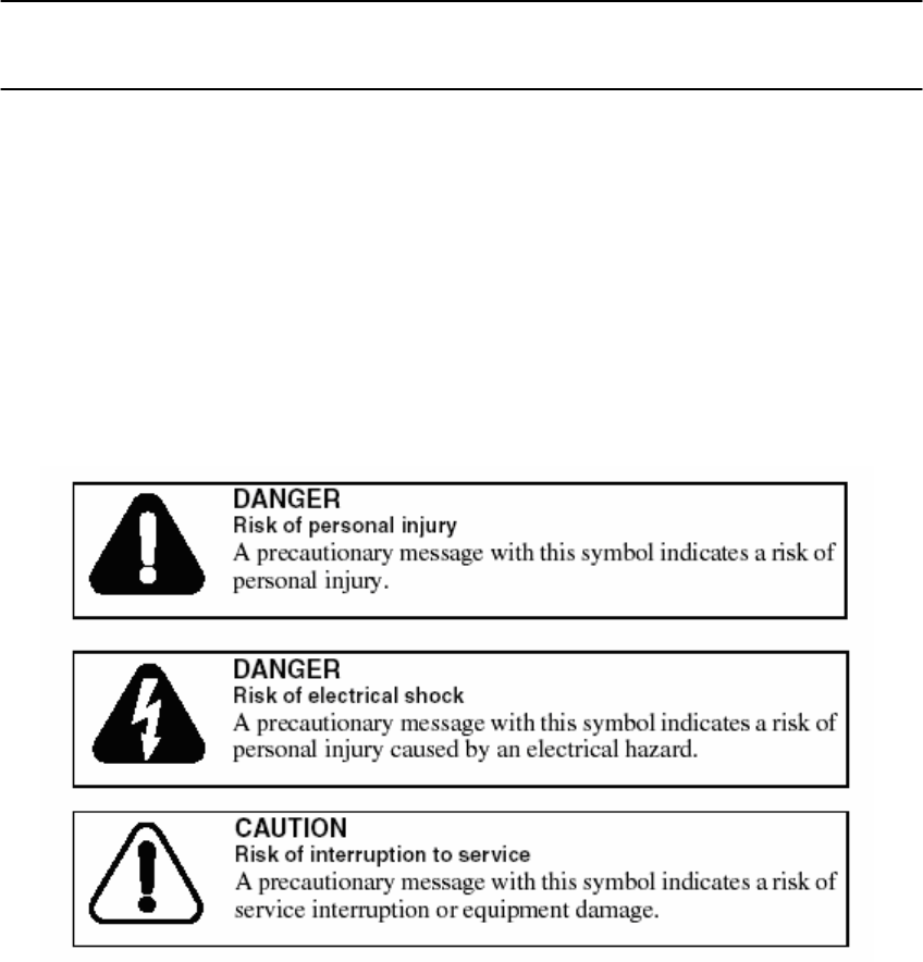
The following precautionary messages appear in WLAN Cable Access Point
6220 documentation:
The graphic symbol of an exclamation point within an equilateral triangle warns
the user of the device that it is necessary to refer to the instruction manual and its
warnings for proper operation of the unit.
11
WLAN Cable Access Point 6220 NTPM99CA Rel 1.0 Issue 2 Nov 2004
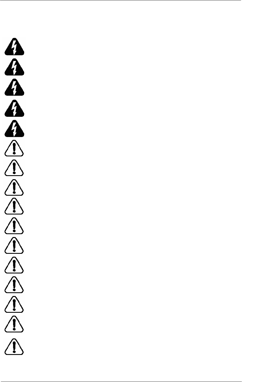
Summary of Warning and Safety Precautions
MAKE SURE THAT POWER SUPPLIER IN HFC NETWORK IS TURNED OFF
PRIOR TO CONNECTING THE COAXIAL CABLE TO THE CABLE ENTRY
CONNECTOR ON APU ENCLOSURE.
DO NOT FASTEN OR UNFASTEN THE COAXIAL CABLE CONNECTOR ON THE
APU WITH UNDER THE UNIT POWERED.
DO NOT CONNECT OR INJECT ANY AC POWER EXCEPT CATV UPS/POWER
SUPPLY. SUCH A MISTAKE WILL CAUSE APU TO BE SERIOUSLY DAMAGED.
REFER SERVICING TO A QUALIFIED TECHNICIAN TO REDUCE THE RISK OF
ELECTRIC SHOCK WHEN THE UNIT DOES NOT APPEAR TO OPERATE
NORMALLY OR EXHIBITS A MARKED CHANGE IN PERFORMANCE.
WHEN INSTALLING THE UNIT, CHOOSE A LOCATION THAT PROVIDES A
MINIMUM SEPARATION OF 20 cm FROM ALL PERSONS DURING NORMAL
OPERATION.
THE APU AND CSU SHALL BE INSTALLED BY A PROFESSIONAL FIELD
TECHNICIAN
BOTH TYPES OF UNITS SHOULD BE INSTALLED BY A PROFESSIONAL FIELD
TECHNICIAN TO REMOVE THE POSSIBILITY OF INCORRECT INSTALLATION
FOR APU AND CSU.
DO NOT EXPOSE THIS UNIT TO RAIN, MOISTURE OR DUST UNCOVERED.
BE SURE NOT TO BE SITUATED NEAR HIGH VOLTAGE POWER SOURCES.
MAKE SURE THAT ALL BOLTS ON THE ENCLOSURE ARE TIGHTENED FIRMLY
SO THAT WATER DOES NOT ENTER THE UNIT.
BE SURE THAT ALL CONNECTORS ARE CONNECTED TO THE UNIT AND THE
RF CABLE HAS BEEN PROTECTED BY THE WATER-PROOF CAP.
BE SURE THAT THE POWER SUPPLY UNIT THAT PROVIDES AC POWER TO
THE APU OPERATES WITHIN THE GUIDELINES IN THIS MANUAL.
IF YOU ARE NOT SURE OF THE TYPE OF POWER SUPPLIED TO YOUR UNIT,
CONSULT YOUR LOCAL NORTEL NETWORKS REPRESENTATIVE OR
NETWORK SERVICE COMPANY.
BE SURE THAT THE RADIO ANTENNA IS LOCATED AWAY FROM ALL POWER
FACILITIES SUCH AS CABLE OR POWER SUPPLIERS.
NEVER PUSH OBJECTS OF ANY KIND INTO THE UNIT. IT MAY TOUCH
DANGEROUS VOLTAGE POINTS OR SHORT-OUT PARTS THAT COULD CAUSE
AN ELECTRIC SHOCK.
DO NOT ATTEMPT TO HANDLE THE UNIT YOURSELF. WITHOUT FULL
KNOWLEDGE OF THE OPERATIONS AND CHARACTERISTICS OF THE APU
PRODUCT AS OPENING OR REMOVING COVERS MAY EXPOSE YOU TO
DANGEROUS VOLTAGE OR OTHER HAZARDS.

13
Overview
Introduction
This document describes the system features used in the WLAN Cable Access
Point 6220 Release 1.0 Product.
The Wireless LAN Cable Access Point 6220 is an outdoor hardened, strand-
mountable access point solution designed to extend the reach of the cable
operators’ hybrid fiber coax network utilizing wireless technologies from
existing rights of ways. This solution from Nortel Networks provides cable
operators a fast, low-cost alternative for delivering service to new customers by
eliminating the time, permits, and construction costs associated with extending
aerial or buried drops.
The WLAN Cable Access Point 6220 solution provides:
Flexible service platform
The WLAN Cable Access Point 6220 is a flexible service platform giving cable
operators the ability to offer many different wireless services such as Public Hot
Spots and Commercial High Speed Data services.
Standard Compliance and Interoperability
The WLAN Cable Access Point 6220 utilizes standard-compliant DOCSISTM
cable modems, thus ensuring interoperability with the existing cable network.
Wireless access is accomplished using industry-standard IEEE 802.11 radios
approved by government regulatory agencies for use in “unlicensed” ISM
frequencies.
14
WLAN Cable Access Point 6220 NTPM99CA Rel 1.0 Issue 2 Nov 2004
Security
Security is of the highest importance when delivering wireless services. The
WLAN Cable Access Point 6220 adheres to industry standards for 802.11
devices and augments those standards with additional security features designed
to provide both the cable operator and the end-user maximum protection.
Performance optimization via multiple antenna options
Nortel Networks provides antenna options specifically engineered to enable the
WLAN Cable Access Point 6220 to achieve peak link performance in Line of
Sight (LOS) and Near LOS applications.
Ease of installation
Designed for simple, fast installation by professional technicians, the WLAN
Cable Access Point 6220 is installed in a simple three-step procedure: lock down
strand clamps, connect power via coax drop, and attach and align antenna for
service optimization
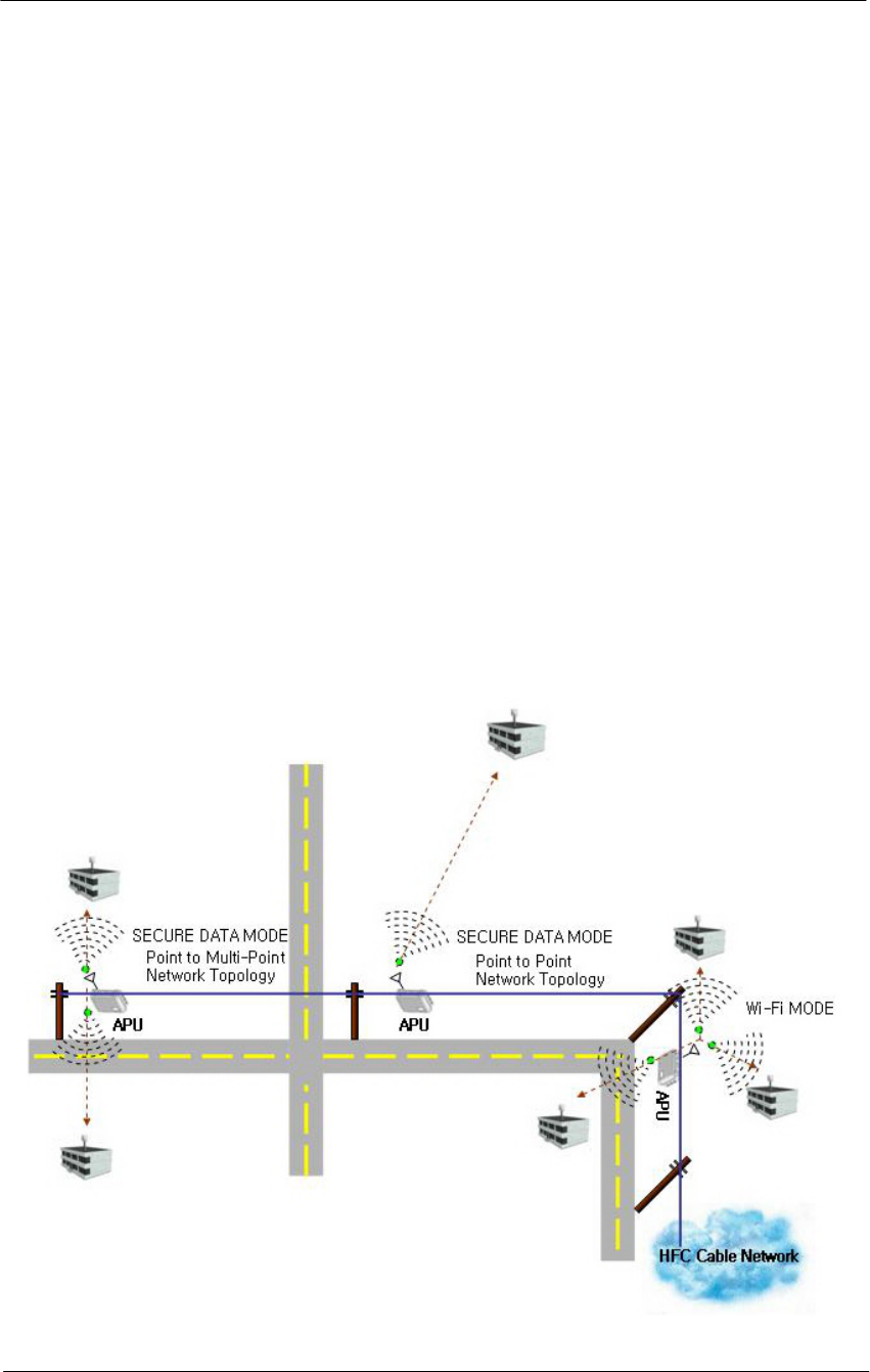
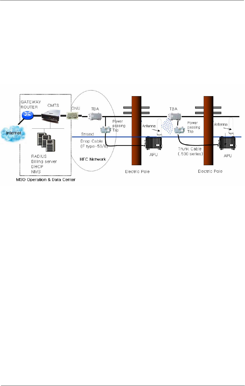
Figure 1-1
WLAN Cable Access Point 6220 Service Concept Diagram

15
WLAN Cable Access Point 6220 NTPM99CA Rel 1.0 Issue 2 Nov 2004
Product Description
Table 1-1
WLAN Cable Access Point 6220 Products
PEC DESCRIPTION
APU
NTPM99AC APU,2.4G,B RADIO,Cable Modem,NA,6Mhz
NTPM99AE KIT APU,2.4G,FP ANTENNA, 14 dB gain,NA,6Mhz
NTPM99AF KIT APU,2.4G,OMNI ANTENNA, 7dB gain,NA,6Mhz
NTPM99AP KIT APU, 2.4G, 2412N ANTENNA, 9dB peak,NA,6Mhz
NTPM99AR APU,2.4G,B RADIO,Cable Modem,8Mhz
Accessories
NTPM99EA APU Antenna Mounting Kit
NTPM99EB Flat Panel Antenna connection cable SMA(M) to N(M)
NTPM99EC OMNI Antenna connection cable N(M) to N(M)
NTPM99ED Antenna - Flat panel 14 dB gain
NTPM99EE Antenna - Omni directional 7dB gain
NTPM99EF Antenna - 2412 Bi DIrectional
NTPM99EG CSU MOUNTING KIT
CSU
NTPM99BC CSU,2.4G,B RADIO,Flat Panel, NA, 6Mhz
NTPM99BJ CSU,POE INJECTOR
NTPM99BK CSU,2.4G,B RADIO, Flat Panel (EU)
Documentation
NTPM99CA R1.0 WLAN6220 CAP DOC,PAPER
NTPM99CB R1.0 WLAN6220 CAP DOC,CD
Software
NTPM99DA R1.0 WLAN6220 CAP SOFTWARE,CD
NTPM99DB CERTIFICAT,WLAN6220,R1.0,1/APU
NTPM99DC CERTIFICAT,WLAN6220,R1.0,1/CSU
APU Software Licenses
NTPM99FA RTU,SDM,WLAN6220,1/APU
NTPM99FB RTU Hotspot, WLAN6220, 1/APU
NTPM99GA SLU,WLAN6220,1/APU
NTPM99GB NSLU,WLAN6220,1/APU
CSU Software Licenses
NTPM99HA RTU,SDM,WLAN6220,1/CSU
NTPM99JA SLU,WLAN6220,1/CSU
NTPM99JB NSLU,WLAN6220,1/CSU
16
WLAN Cable Access Point 6220 NTPM99CA Rel 1.0 Issue 2 Nov 2004
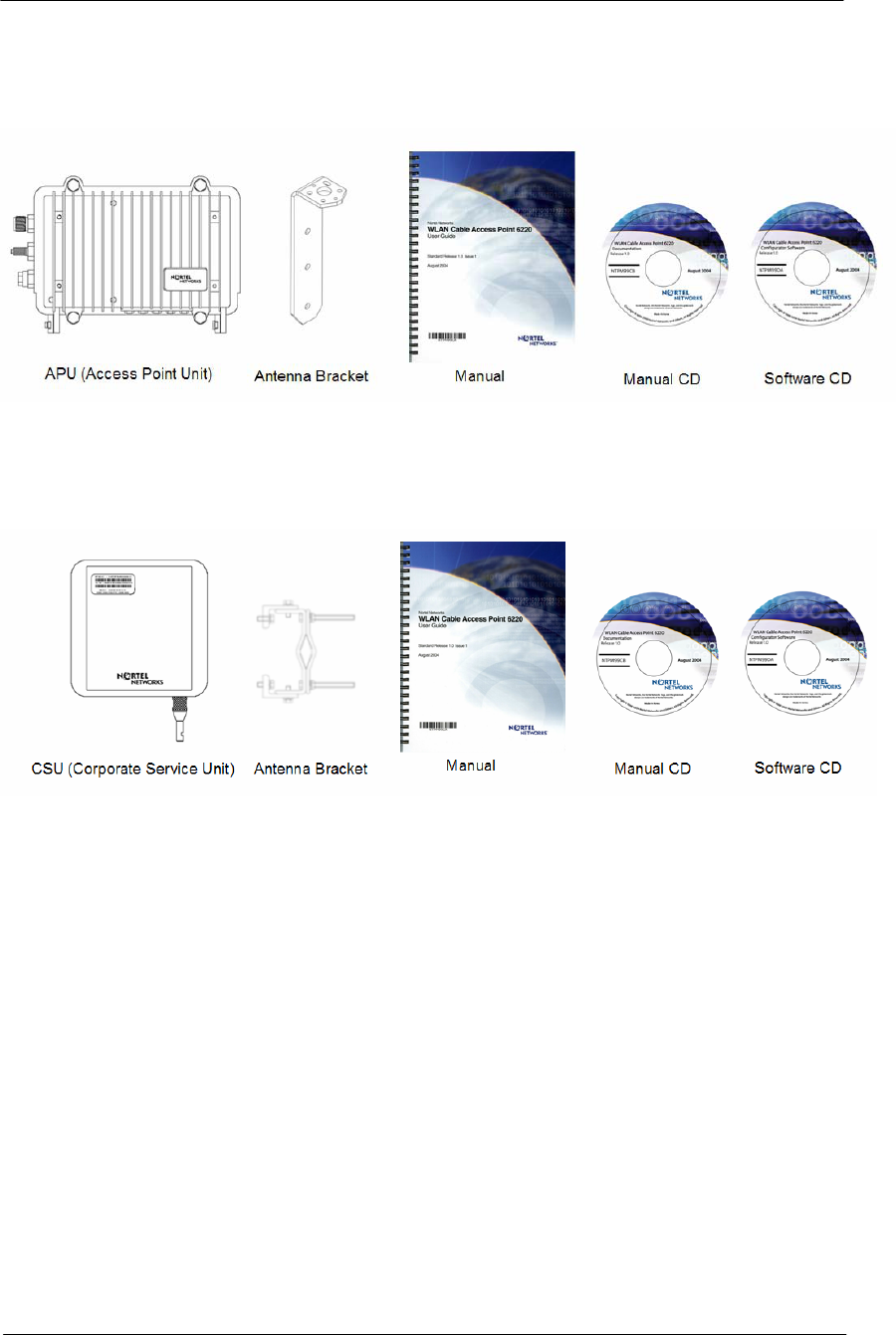
Figure 1-2
WLAN Cable Access Point 6220 APU Package Components
Figure 1-3
WLAN Cable Access Point 6220 CSU Package Components

17
WLAN Cable Access Point 6220 NTPM99CA Rel 1.0 Issue 2 Nov 2004
APU (Access Point Unit)
The following is a list of WLAN Cable Access Point 6220 APU features:
• Enclosure has three sorts of connectors which support the connection to
CATV Cable Network, Antenna and Monitoring Equipment.
• Coaxial Port has the standard type of connector that can be efficiently
adapted to every connector regardless of the termination type of coaxial
cable such as “Trunk or Drop Cable”
• Operation Power and Data Traffic are mixed at a signal amplifier as TBA
(Trunk Bridge Amplifier), PI (Power Inserter) and supplied to the coaxial
port on the APU through coaxial cable.
• Monitoring Port can provide the safe testing method for measuring CATV
signal to an installation engineer by attenuating RF power and protect AC
power signal.
• Basically, two kinds of mounting types are available for the APU, such as a
steel wire strand mounting and wall mounting, but in case of wall
mounting, another optional bracket kit will be needed for installation.
• The three available antennas are ‘Directional Type’, ’Bi-directional Type’
and ‘Omni-directional Type’, which can be mounted on the front or rear
cover of the APU with a Universal Bracket.
• Cable Modem Module is compliant to DOCSIS 2.0(Cablelabs) as well as
DOCSIS 1.1 and WLAN AP support the secure mode connection which
means that wireless traffic from APU and CSU is not scanned and detected
by a conventional sniffing program like ‘Netstumbler’.
18
WLAN Cable Access Point 6220 NTPM99CA Rel 1.0 Issue 2 Nov 2004
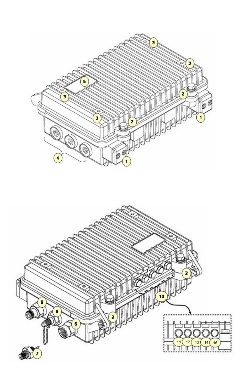
Figure 1-4
APU (Top head)
Figure 1-5
APU (Bottom)

19
WLAN Cable Access Point 6220 NTPM99CA Rel 1.0 Issue 2 Nov 2004
Figure 1-6
Inner Panel (APU)
20
WLAN Cable Access Point 6220 NTPM99CA Rel 1.0 Issue 2 Nov 2004
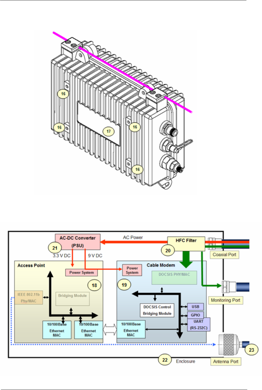
Figure 1-7
APU (Back)
Figure 1-8
APU System Structure and Signal Flow

21
WLAN Cable Access Point 6220 NTPM99CA Rel 1.0 Issue 2 Nov 2004
Table 1-2. Modules and Connectors (APU)
Item Label Description & Function
1 Clamp Module Provide strand mounting function to APU, Strand Clamp and Mount Bosses
2 Lid Bolt Lid Bolt for closing a case of APU enclosure
3 Antenna Mount Hole Screw Holes for mounting a APU antenna with a universal bracket
4 Reserved Port Reserved Location for a future upgrade and revision
5 Logo Panel Location for Nortel networks Logo
6 Cable Entry Port Port for coaxial cable connection. Trunk and Drop termination types are supported
7 Cable Adaptor Coaxial Adaptor Port to connect F-type Drop cable to APU Cable Entry Port
8 Monitoring Port Port reserved for safe testing of Cable RF signal. The signal on this port is attenuated by 20 dB
9 Antenna Port Port for antenna connection
10 LED Panel Provide the information for system operation status through LED Display
11 LED1(Power) Indicate Power is turned on
ON Indicate a valid cable modem operation
12 LED2(Link #1) Flash Indicate that cable modem is linked up on the HFC network
ON Indicates a Ethernet link between access point and cable modem
13 LED3(Link #2)
Flash Indicates that the access point is transmitting or receiving data
ON Indicates the 802.11b radio is enabled and operating
14 LED4(Radio #1) Flash Indicate that a frame is transmitted or received on the radio port
15 Reserved Reserved location for a future upgrade
16 Antenna Mount Hole
Grounding Hole Screw Holes for mounting a APU antenna with a universal bracket and grounding the APU
enclosure
17 Label Location for attaching a product label which include S/N,PEC,MAC address and so on
18 Access Point Mini-PCI type III Radio Card, System Board(Wi-Fi & Secure Data Mode TM)
19 Cable Modem DOCSIS 2.0 compliant cable modem
20 HFC Filter Split a HFC Signal and AC power from the combined signal
21 PSU AC to DC Power converter
22 Case Housing case which can be mounted on strand and antenna mounting bracket
23 Antenna
2.4GHz Radio Frequency Antenna (Flat Panel, Omni-directional and Bi-directional).
APU antenna can be mounted on the front or rear cover of APU with universal bracket.
24 Inner Panel Cover Panel to secure the main system boards(WLAN AP, Cable Modem)
25 USB Port USB type port for testing the Cable Modem Module
26 DC Connector 3-pin connector to supply DC power to system board from Power Converter
27 Ethernet Port Port to connect APU to laptop/PC for testing purpose
28 Reset S/W Switch to reset the system to default settings
29 Cable Modem LED Indicate the full status of Cable Modem
30 Access Point LED Indicate the full status of Access Point

22
WLAN Cable Access Point 6220 NTPM99CA Rel 1.0 Issue 2 Nov 2004
CSU (Corporate Service Unit)
The following is a list of WLAN Cable Access Point 6220 CSU features:
• Enclosure has a POE connection interface and a DC Power Adapter Jack at
the bottom of the CSU.
• Operation Power & Data Traffic are mixed at POE Injector and supplied to
the Ethernet Port on the CSU through CAT5 Cable.
• Two types of mounting alternatives are available, pole mount and wall
mount. If wall mount is used a mounting kit will be required.
• The antenna is basically a Flat Panel type which is a built-in CSU body
protected by a plastic material RADOME.
• WLAN AP supports the secure mode connection which means that wireless
traffic from APU and CSU is not scanned and detected by a conventional
sniffing program like ‘Netstumbler’.
23
WLAN Cable Access Point 6220 NTPM99CA Rel 1.0 Issue 2 Nov 2004
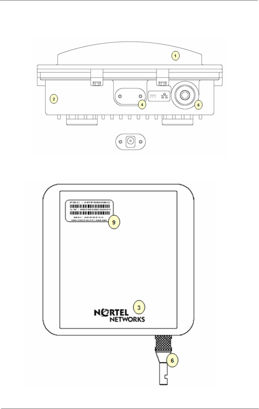
Figure 1-9
WLAN Cable Access Point 6220 CSU (Bottom)
Figure 1-10
WLAN Cable Access Point 6220 CSU (Front)
24
WLAN Cable Access Point 6220 NTPM99CA Rel 1.0 Issue 2 Nov 2004
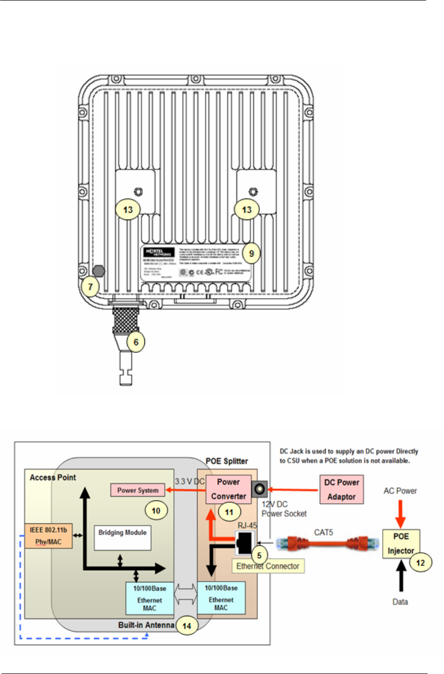
Figure 1-11
WLAN Cable Access Point 6220 CSU (Back)
Figure 1-12
WLAN Cable Access Point 6220 CSU
25
WLAN Cable Access Point 6220 NTPM99CA Rel 1.0 Issue 2 Nov 2004
Table 1-3. Modules and Connectors (CSU)
Item Label Description & Function
1 Antenna Radome Protective Cover designed to contain a built-in antenna
2 Enclosure(Body) Housing Integrated with an Antenna Case Assembly
3 Logo Panel Location for Nortel networks Logo
4 DC Power Socket Provide DC power(12V) from AC-DC Adaptor to CSU
5 Ethernet Port(POE) Provide data connection between CSU and POE Injector or LAN Switch
6 EMI Cap
EMI Cap designed to prevent CSU from interfering to or from other devices
Additionally, provide water proof feature accompanied by sealing tape
7 Ground Point Location for grounding the enclosure to earth for protecting the product from damage
8 Label(Front) Location for attaching a product label which include S/N,PEC,MAC address and so on
9 Label(Back) Location for attaching a product label which include S/N,PEC,MAC address and so on
10 Access Point Mini-PCI type III Radio Card, System Board(Wi-Fi & Secure Mode TM)
11 POE Splitter Power Module to divide Ethernet Signal and DC power combined signal from POE Injector
12 POE Injector Provide 802.3af based signal to CSU through Ethernet Port on CSU
13 Bracket Hole Bolt Hole for assembly of mounting bracket
14 Built-in Antenna 2.4GHz Radio Frequency Antenna (Flat Panel)
THE 12V POWER CONNECTOR IS NOT INTENDED FOR FIELD USE. THIS
SOCKET IS ONLY APPLICABLE FOR A SPECIAL USE AT FACTORY OR
REPAIR FACILITY.

27
Planning your WLAN Network
The wireless network is much different than a wired network. The
Installation of a wireless network requires some additional planning.
This planning includes RF Link Engineering like RF Path planning, site
selection, and back-bone network preparation.
The radio links between all end sites are specified as three types of
environmental connection as listed below:
LOS(Line Of Sight)
OLOS(Optical LOS)
NLOS(Non LOS)
Because High Frequency Radio travels in a straight forward line, a clear
LOS(line-of-sight) between antennas is efficient and ideal. Frequently,
locations of the desired links are fixed.
When you cannot achieve a clear line-of-sight, you must plan according
to basic consideration:
The Basic considerations for sites include:
▪ Installation Facility must be constructed (Electric Pole, Tower)
▪ Possibility of future obstructions
- Trees that may obstruct the path
- Buildings between the sites that may obstruct the path
▪ Lightening
▪ Distance between sites and Network Structure
▪ Strong RF interference

28
WLAN Cable Access Point 6220 NTPM99CA Rel 1.0 Issue 2 Nov 2004
Site Survey & Planning
Definition
A site survey is a task-by-task process by which the surveyor discovers
the RF behavior, coverage, interference, and determines proper hardware
placement in a facility. The site survey’s primary objective is to ensure
that mobile workers and the wireless LAN’s clients experience
continuously strong RF signal as they move around the facility.
Items
• Facilities Analysis
• Existing Networks
• Area Usage & Towers
• Purpose & Business Requirements
• Bandwidth & Roaming Requirements
• Available Resources
• Security Requirements
• Preparation Exercises
• Preparation Checklist
Site Survey Equipment
• Corporate service unit(CSU) with POE Injector
• Laptop and/or PDA
• Wireless PC card with driver & utility software
• Battery pack charger & DC-to AC converter
• Site survey utility software (loaded on laptop or PDA)
• Clipboard, pen, pencils, notebook paper, grid paper, & highlighter
• Blueprints & network diagrams
• Outdoor antennas(Omni-directional, Patch, Bi-directional)
• Cables & connectors
• Specialized software or hardware such as a spectrum analyzer
• Digital camera for taking pictures of particular locations within a
facility
• Variable attenuator

29
WLAN Cable Access Point 6220 NTPM99CA Rel 1.0 Issue 2 Nov 2004
Wireless Network Planning
Procedure 1 (Location)
1. Select and identify enough location candidates to determine freely as
the install point regardless of some design change to some extent.
2. The most crucial parameter is the range at which APU and CSU or
other Wi-Fi Client is required to operate. The range can be
determined by a conventional formula which consider a various kinds
of environmental and radio equipment.
3. Another consideration in installing APU and CSU is the network
connection like a CATV Coaxial Cable and CAT5 Ethernet Cable.
Even though some locations are the best location in terms of RF
performance, the actual installed location is restricted by limited
cable reach.
Procedure 2 (Radio Link Path)
1. Choose the proper antenna type with a site survey result.
2. For best performance, mount the APU and CSU in a location where
there is LOS (Line Of Sight) to each antenna.
3. Perform the field survey to summarize every obstacle like tree and
earth bulge in consideration of OLOS (Optical LOS).
4. With the site survey result, adjust the tilt and angle of antenna so that
there is maximum clearance within the FRESNEL ZONE of the
direct path.
Note: The best means of achieving FRESNEL ZONE clearance is to
raise the height of APU or CSU mounting point as high as possible
5. In order to get the more exact information on RF radio link path,
calculate the Link Budget for Radio Link between APU and CSU
which is referred in the end of this section.
Note: The link budget is a rough calculation of all known elements of the
link to determine whether the signal will have the proper strength to the
other end of the link.
Procedure 3 (RF Channel Selection)
1. Check all range of channels by RF measurement with Frequency
Analyzer in order to see the interference effect with APU and CSU.
Actually, RF interference is likely to arise from any other wireless
system operating within the same frequency band as ISM/UNII Band
Radio Products.
Note: The final selection of operating channel should be done with the
testing results of both APU and CSU.
Procedure 4 (Radio Performance Tuning)
Please refer to the Radio Link Test
31
Installation
General This section provides a complete set of procedures for the installation of
WLAN 6220 equipment. It includes cable assembling information as
well as required connection information for the WLAN 6220 units,
mounting and powering instructions.
It is intended for use by trained installers familiar with CATV or Cable
Modem and Wireless installations.
For technical assistance, contact your next level of support or Nortel
Networks according to the information available in Technical Support
and Information section.
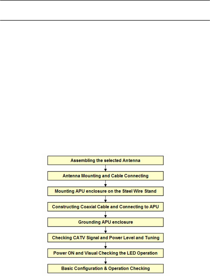
Installation Procedure Summary
APU (Access Point Unit)
32
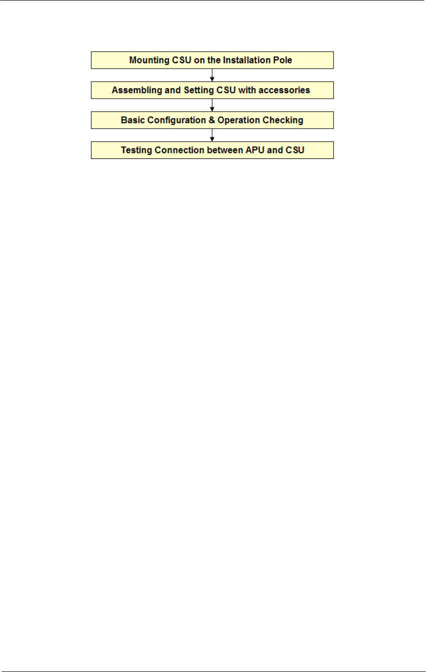
WLAN Cable Access Point 6220 NTPM99CA Rel 1.0 Issue 2 Nov 2004
CSU (Corporate Service Unit)
Required Tools and Materials
Before you install the WLAN Cable Access Point 6220, ensure you have
the following:
APU
WLAN Cable Access Point 6220 APU package does not contain an
antenna and universal antenna bracket kit. For list of antennas and
accessories, see the WLAN Cable AP 6220 manual or contact your local
Nortel networks representative.
One or more antenna cables (N-Male to the connector on the
external antenna)
External antennas selected by yourself
Flat blade screwdrivers
Wire cutters
Phillips screwdriver
Torque wrench/driver
Other proper tools for installation
Heat gun with propane/Mapp torch
Trunk & Distribution Cable Connector and Drop Cable F-
connector port
RF cable for connecting between the APU and Testing Unit (if
needed)
Portable CATV Spectrum Analyzer
DVM(Digital Voltammeter)
“Document CD” and “Software CD” that contains the APU
Configurator, online help for the Configurator, and various
documents.
Advanced Tool: RF Testing Unit: CSU, Laptop computer with
radio card

33
WLAN Cable Access Point 6220 NTPM99CA Rel 1.0 Issue 2 Nov 2004
CSU
IEEE 802.3af-2003-compliant Power over Ethernet (POE) injector
Note: Ensure that the POE Injector is UL/cUL approved,
with LPS (limited power source) output.
Heat gun with propane/ Mapp torch
1 CAT5 Ethernet Extender Coupler
“Document CD” and “Software CD” that contains the APU
Configurator, online help for the System Configuration, and
various documents.
PC or workstation with a Web browser for configuration
34
WLAN Cable Access Point 6220 NTPM99CA Rel 1.0 Issue 2 Nov 2004
APU Installation & Configuration
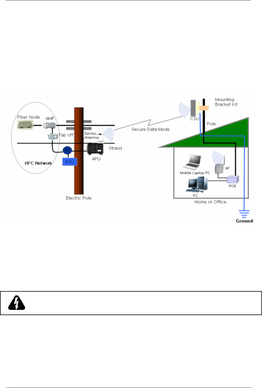
Mounting and Installation Concept
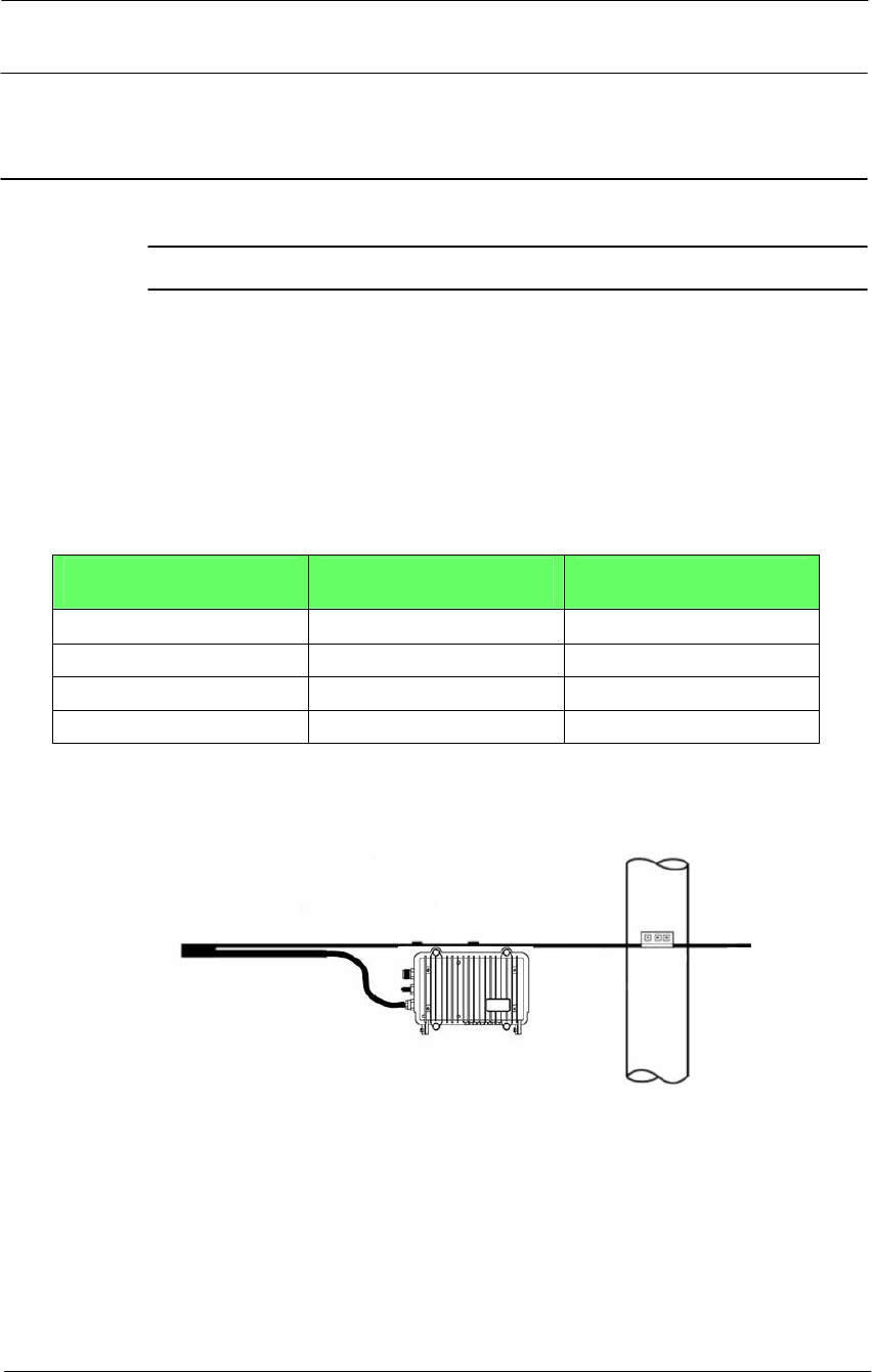
Figure 3-1
APU Installation Concept on CATV Network Facility
By default, APU is strand mountable. Each unit is shipped with a strand
clamp module.
Both Drop and Trunk cable termination types are applicable to the APU.
The recommended method is Drop cable.
The APU supports a variety of antenna types: omni-directional, flat panel
and bi-directional. The antenna type should be selected according to the
coverage needed and type of application - please refer to Appendix H for
more detailed information.

35
WLAN Cable Access Point 6220 NTPM99CA Rel 1.0 Issue 2 Nov 2004
Procedure 1-1
Assembling and Mounting the selected Antenna
Common Procedure
1. Unpack the antenna box and check the contents listed in the manual
in the box.
2. Prepare the recommended tools for assembly and installation of the
antenna.
3. Assemble the antenna and bracket kit following the assembly
procedure for the selected antenna type.
4. Perform assembly of antenna and bracket as below.
Action
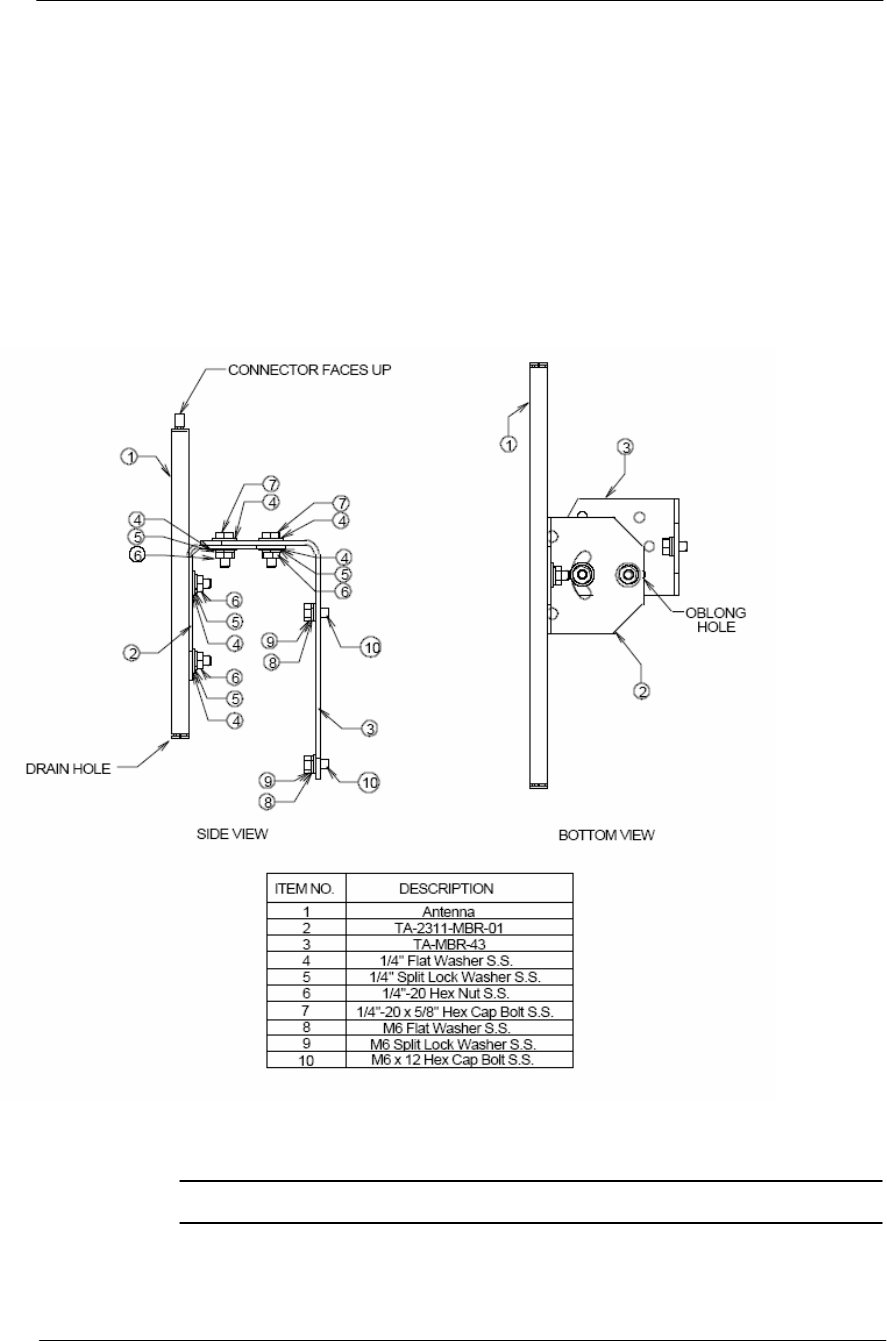
NTA 2407 (Flat Panel Antenna)
Step Action
1. Ensure that each part number is the same as the actual part in the box.
2. Attach the 2311 mounting bracket #1 to the antenna using the 1/4"
flat washers, lock washers and hex nuts as shown in the mounting
drawing.
3. Attach the 2311 mounting bracket #1 to mounting bracket #43 using
the 1/4" flat washers, lock washers, hex nuts, and hex bolts as shown
in the diagram. Ensure that the brackets are attached through the
oblong hole in mounting bracket #43.
4. With the antenna connector oriented upward, fasten mounting
bracket #43 to the radio using the M6 flat washers, lock washers, and
hex bolts as shown in the mounting diagram.
5. To adjust the pan of the antenna, loosen the 1/4" hex bolts that attach
the 2311 mounting bracket #1 with mounting bracket #43, adjust the
pan, and re-tighten the bolts.
Lightning Protection
The antenna is at DC ground for lightning protection. If the antenna is
mounted to a non-conductive structure it should in turn be grounded
using practices supplied/approved by the customer.
Weatherproofing
All connections between the antenna connector and the transmission line
must be weatherproofed according to standard industry practices.
36
WLAN Cable Access Point 6220 NTPM99CA Rel 1.0 Issue 2 Nov 2004
Drainage
Since the RADOME is not pressurized, there is a drain hole in the
connector base plate. The antenna must be installed so that the drain hole
remains on the bottom. This drain hole must be kept open so that any
moisture accumulating inside the RADOME will be able to drain
properly.
Figure 3-2
NTA-2407 Antenna Assembly
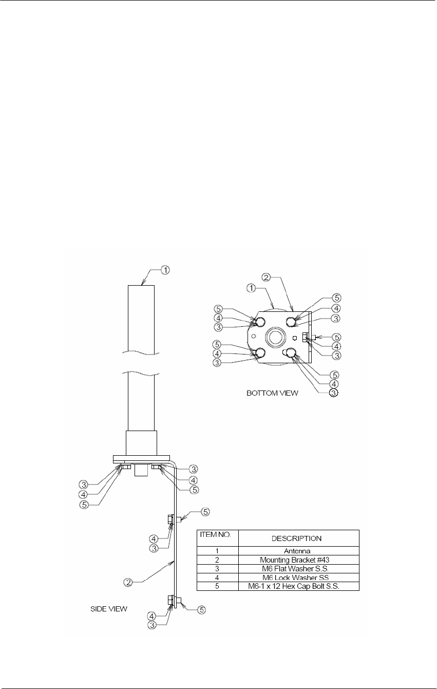
NTA 2400 (Omni directional Antenna)
Step Action
1. Ensure that each part number matches the actual part in the box.
2. Attach the mounting bracket to the antenna using the M6 flat washers,
lock washers and hex cap bolts as shown in the mounting drawing.
37
WLAN Cable Access Point 6220 NTPM99CA Rel 1.0 Issue 2 Nov 2004
3. With the antenna oriented upward, fasten the mounting bracket to the
radio using the M6 flat washers, lock washers, and hex cap bolts as
shown in the mounting diagram.
Lightning Protection
The antenna is at DC ground for lightning protection. If the antenna is
mounted to a non-conductive structure (e.g. building wall, wooden pole
etc.) it should in turn be grounded using practices supplied/approved by
the customer.
Weatherproofing
All connections between the antenna connector and the transmission line
must be weatherproofed according to standard industry practices.
Figure 3-3
NTA-2400 Antenna Assembly

38
WLAN Cable Access Point 6220 NTPM99CA Rel 1.0 Issue 2 Nov 2004
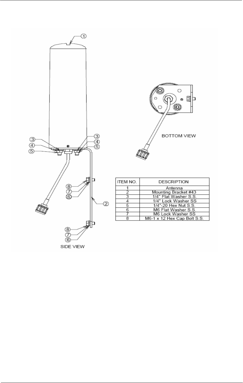
NTA 2412 (Bi-directional Antenna)
Step Action
1. Ensure that each part number matches the actual part in the box.
2. Attach the mounting bracket to the antenna using the 1/4" flat
washers, lock washers and hex nuts as shown in the mounting
drawing.
3. With the antenna oriented upward, fasten the mounting bracket to the
radio using the M6 flat washers, lock washers, and hex bolts as
shown in the mounting diagram.
Lightning Protection
The antenna is at DC ground for lightning protection. If the antenna is
mounted to a non-conductive structure (e.g. building wall, wooden pole
etc.) it should in turn be grounded using practices supplied/approved by
the customer.
Weatherproofing
All connections between the antenna connector and the transmission line
must be weatherproofed according to standard industry practices.
Drainage
Since the RADOME is not pressurized, there is a drain hole in the
connector base plate. The antenna must be installed so that the drain hole
remains on the bottom. This drain hole must be kept open so that any
moisture accumulating inside the RADOME will be able to drain
properly.
39
WLAN Cable Access Point 6220 NTPM99CA Rel 1.0 Issue 2 Nov 2004
Figure 3-4
NTA-2412 Antenna Assembly
40
WLAN Cable Access Point 6220 NTPM99CA Rel 1.0 Issue 2 Nov 2004
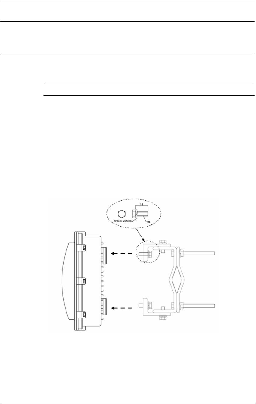
Procedure 1-2
Antenna Mounting and Cable Connecting
Action
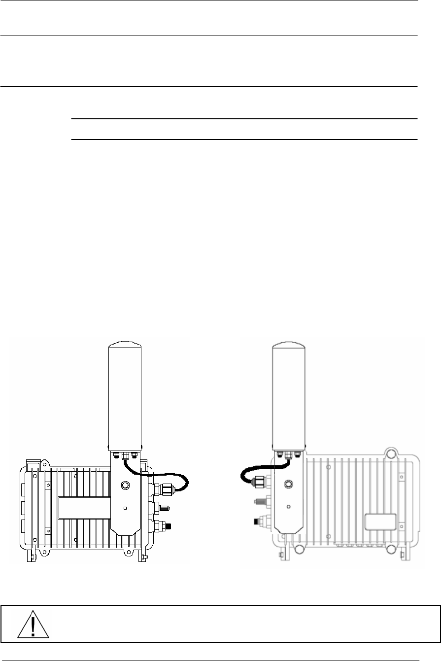
Step Action
1. Attach the bracket on the back surface of the APU and thread one flat
washer onto each hex bolt. Screw each bolt with the washer into the
two mounting holes.
Note: Even if the APU enclosure has universal mounting holes on the
front and rear cover, we recommend that you do not mount two kinds of
antenna such as omni-directional and bi-directional type on the front
cover. If inevitable, the left side of the front cover is the preferred
location in consideration of antenna cable length.
2. Tighten each bolt until the washer is pressed firmly into the APU
Enclosure.
Figure 3-5
Antenna mounting with a bracket
TYPE I TYPE II
BE SURE THAT THE RADIO ANTENNA IS LOCATED AWAY FROM ALL OTHER
POWER FACILITIES LIKE CABLE OR POWER SUPPLIERS.
41
WLAN Cable Access Point 6220 NTPM99CA Rel 1.0 Issue 2 Nov 2004
Procedure 1-3
Mounting the APU on the Steel Wire Strand
Action
Step Action
1. Prior to an installation, check if the strand has the strength to sustain
the weight of the APU or 10 lbs.
Note: During placing the cable, do not exceed the maximum rated
pulling tension of the steel. After the cable has been placed, tension
should be applied to the strand only. Refer to the table of guidelines
found in the current NESC Rules 250-252.
Table 3-1
Strand Tension and limitation
Strand Diagram
inches (mm) Weight
lbs/ft (kg/m) Max rated Load
lbs (kg)
0.109 (2.77) 0.032 (0.048) 1800 (816)
0.134 (3.40) 0.048 (0.075) 2680 (1216)
0.188 (4.77) 0.073 (0.109) 3990 (1810)
0.250 (6.35) 0.121 (0.180) 6650 (3016)
Figure 3-6
APU Installation scheme
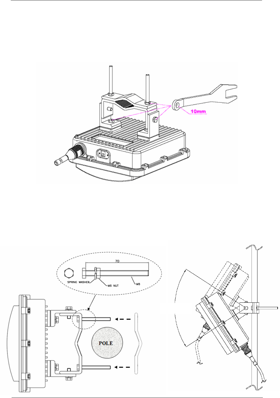
2. Attach the strand clamp assemblies to the top strand clamp bosses
(mounting surfaces) with a long socket cap screw bolt (Diameter: 5
mm, Length: 15mm) and lock washers.
3. Slide the wire strand into the clamp module.
4. Tighten the bolts with the power tool that has a hex head socket bit
so that the enclosure cannot come off the strand, while the location
can still be adjusted.
5. Torque the clamp bolts to between 35 and 60 in-lbs (3.9 and 6.8 Nm).

42
WLAN Cable Access Point 6220 NTPM99CA Rel 1.0 Issue 2 Nov 2004
Figure 3-7
Unfastening the Strand Mounting Clamps on the APU
Figure 3-8
Mounting the APU on the Strand by tightening the socket cap screw bolt
ENSURE THAT ALL BOLTS IN THE ENCLOSURE ARE FIRMLY TIGHTENED.
WHEN INSTALLING THE UNIT, CHOOSE A LOCATION THAT PROVIDES A
MINIMUM SEPARATION OF 20 cm FROM ALL PERSONS DURING NORMAL
OPERATION.
43
WLAN Cable Access Point 6220 NTPM99CA Rel 1.0 Issue 2 Nov 2004
Procedure 1-4
Constructing Coaxial Cable and Connecting to the APU
Common Procedure
1. Prior to installation, choose a type of coaxial cable to be connected to
the APU.
- Trunk & Distribution Cable and Connectors : “.500 series”
- Drop Cable and Connector : “F-type RG-59/6”
2. Perform installation of the coaxial cable as below.
Action
Trunk Cable Connection
Step Action
1. Prepare “.500 series Coaxial Cable”, GRS Type connector and all
required Tools for Terminator, Coring, Jacket stripper and
Compression
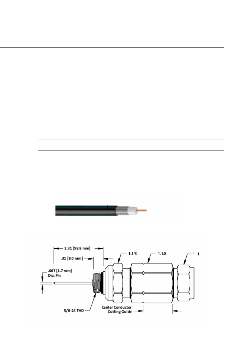
Figure 3-9
Trunk and Distribution Cable
Figure 3-10
Trunk Connector Design
2. Remove the outer jacket/armor to expose the inner jacket, noting that
the removal of the outer jacket must be completed without scoring
the inner jacket.
44
WLAN Cable Access Point 6220 NTPM99CA Rel 1.0 Issue 2 Nov 2004
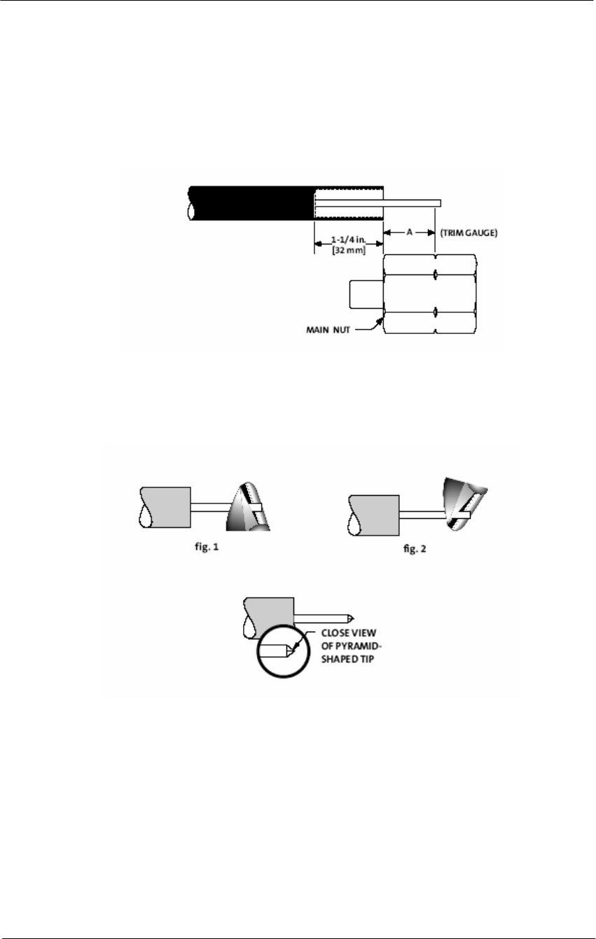
3. Using the built-in trim gauge, verify the center conductor, trim
length(15/16 inch: 24mm) and remove the dielectric to a depth of 1
1/4 inch(32mm) from the end of the outer conductor.
Figure 3-11
Constructing Trunk and Distribution Coaxial Cable
4. After all dielectric and pre-coats have been removed from the center
conductor, re-check the center conductor length and trim accordingly.
Figure 3-12
Shading the tip of the center conductor
5. Make a cut halfway though and rotate the cutters 90° and complete
the cut.
6. Slide the heat shrink tubing over the cable.
7. Remove the outer jacket to a length of ½” (12.7mm).
8. Install the back nut into the cable.
9. Remove and clean flooding material.
10. Install the main nut onto the cable, as a final check on both coring
depth and center conductor length. The center conductor will
protrude 1/16” to 1/8” past the end of the main nut.
11. Ensure that the cable is fully inserted into the connector so that the
jacket butts up against the outer conductor seizing mechanism.
45
WLAN Cable Access Point 6220 NTPM99CA Rel 1.0 Issue 2 Nov 2004
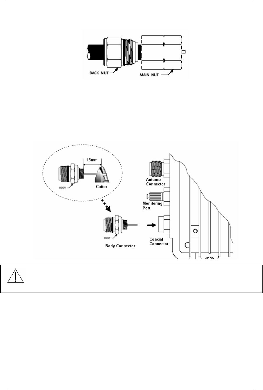
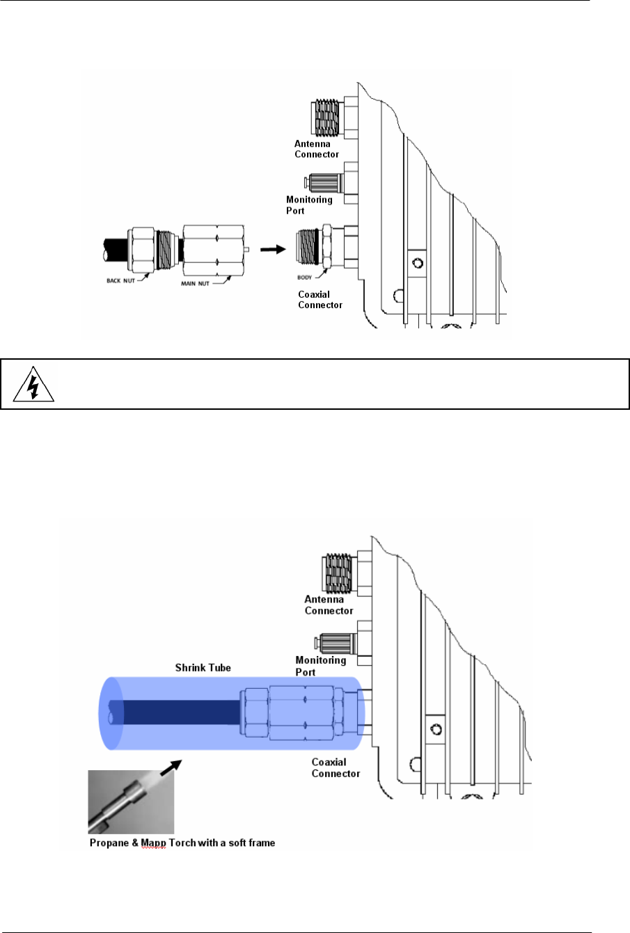
Figure 3-13
Combining Back Nut with Main Nut
12. In order to prevent damage to the connector on the APU enclosure,
cut the pin of the Body connector to the length of 0.59” (15mm) with
a cutting tool.
13. Install the Body connector to the enclosure and tighten firmly.
Figure 3-14
Adjusting the length of the center conductor
14. Bring the main nut and cable to the body connector. Hand-tighten the
main nut to the body continually keeping pressure on cable towards
the body so that the center conductor will be properly seized.
15. Using two wrenches, use one wrench to hold the BODY from
rotation and the other to continue tightening the main nut to the body
until a firm stop is reached.
16. Tighten the back nut by hand, and by using two wrenches, one on the
main nut, complete the installation by tightening the back nut firmly
to secure the cable (approximately 35 lbs, ft).
17. Secure the center conductor into the equipment enclosure with the
seizing screw.
ENSURE THAT THE PIN LENGTH OF THE BODY CONNECTOR DOES NOT
EXCEED 15mm (0.59055 inch) TO PREVENT DAMAGE TO THE JOINT
PORTION OF THE HFC FILTER IN THE ENCLOSURE
46
WLAN Cable Access Point 6220 NTPM99CA Rel 1.0 Issue 2 Nov 2004
Figure 3-15
Connecting the main connector module to the connector port
18. Slide the heat shrink tubing over the connector against the APU.
19. Shrink the tubing with a painting motion not concentrating on any
one area using a propane torch with a broad “soft” frame.
Figure 3-16
Shrink the tubing to Water Proof
ENSURE THAT THE POWER SOURCE IS TURNED OFF PRIOR TO CONNECTING
COAXIAL CABLE (75 ohm) TO PROTECT FROM ELECTRICAL SHOCK
47
WLAN Cable Access Point 6220 NTPM99CA Rel 1.0 Issue 2 Nov 2004
Drop Cable Connection
Step Action
1. Prepare “F series Coaxial Cable”, connector and all required Tools
for Terminator, Coring, Jacket stripper and Compression
2. Remove the outer jacket/armor to expose the inner cable. Fold
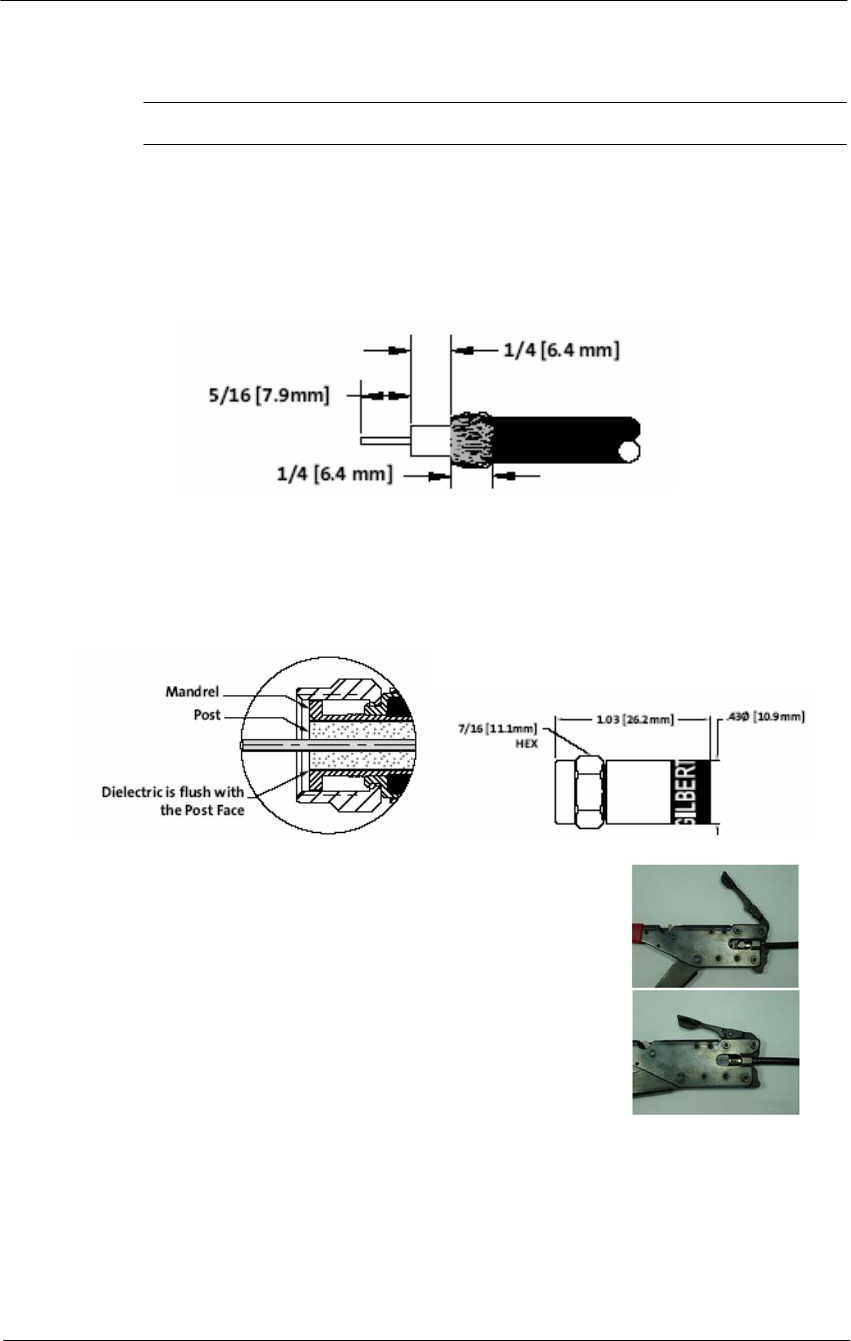
exposed braid back over jacket. Leave foil attached to dielectric.
Figure 3-17
Drop Cable
3. Push connector onto the cable until the cable dielectric is flush with
the connector post face. Approximately 1/4 inch (6.4mm) of center
conductor will protrude beyond the end of the connector nut.
Figure 3-18
Drop Connector Design
4. Slightly angle the connector/cable and insert
into the compression tool area between the
plunger tip and the cable gate allowing the
center conductor to enter the center
conductor guide. Push the cable into the
cable gate. Compress the connector by
squeezing the tool handles together until a
positive stop is reached.
5. Remove the connector/cable from the tool by opening the cable gate
to release the assembly from the tool.
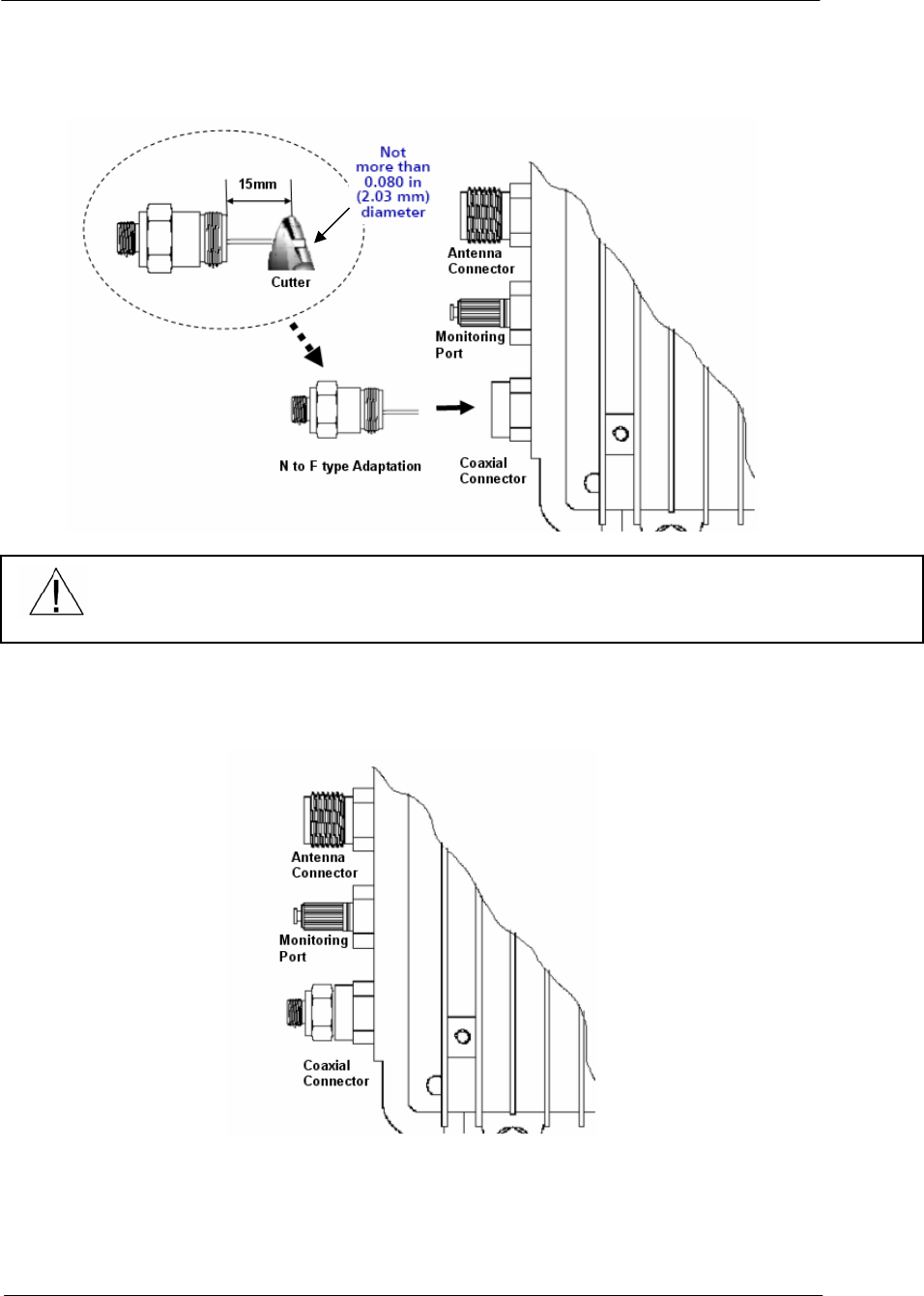
In order to prevent damage to the connector on APU enclosure, cut
the pin of N to F type adapter to the length of 0.59inch (15mm) with
a cutting tool
48
WLAN Cable Access Point 6220 NTPM99CA Rel 1.0 Issue 2 Nov 2004
Figure 3-19
Adjusting the length of the center conductor
6. Install the N to F type Adapter to the enclosure and tighten firmly
Figure 3-20
Connecting the N to F type Adapter to the enclosure
7. Connect a coaxial cable to the F-connector port and fasten enough to
prevent a water intrusion into the gap between connectors.
ENSURE THAT THE PIN LENGTH OF THE ADAPTATION CONNECTOR DOES
NOT EXCEED 15mm(0.59055 inch) TO PREVENT DAMAGE TO THE HFC FILTER
JOINT PORTION IN THE UNIT.
49
WLAN Cable Access Point 6220 NTPM99CA Rel 1.0 Issue 2 Nov 2004
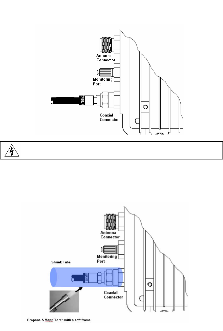
Figure 3-21
Connecting the coaxial cable to the connector port
8. Slide the heat shrink tubing over the connector against the APU.
9. Shrink the tubing with a painting motion not concentrating on any
one area using a propane/Mapp torch with a broad “soft” frame.
Figure 3-22
Shrink the tubing to Water Proof
ENSURE THAT THE POWER SOURCE IS TURNED OFF PRIOR TO CONNECTING
COAXIAL CABLE (75 ohm) TO PROTECT AN INSTALLER FROM ELECTRICAL SHOCK
50
WLAN Cable Access Point 6220 NTPM99CA Rel 1.0 Issue 2 Nov 2004
Procedure 1-5
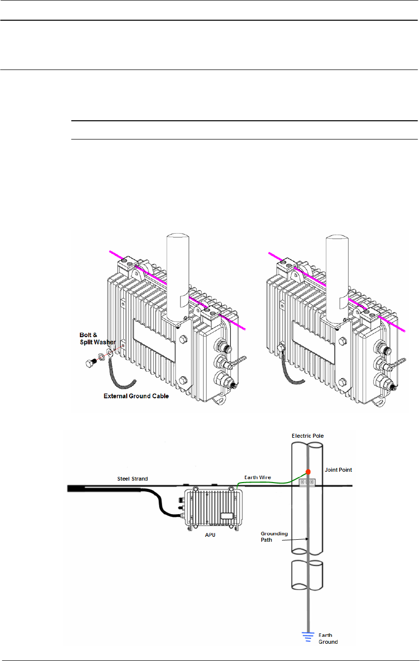
Grounding APU enclosure
Action
Step Action
1. Loosen the grounding bolt and wind the end of the ground wire
around the bolt.
2. Fasten the bolt and the ground wire to the earth by connecting them
to the earth facility.
Figure 3-23
Assembling the grounding bolt and wire
Figure 3-24
Concept diagram of APU enclosure grounding

51
WLAN Cable Access Point 6220 NTPM99CA Rel 1.0 Issue 2 Nov 2004
Procedure 1-6
Checking CATV Signal and Power Level and Tuning
Action
Step Action
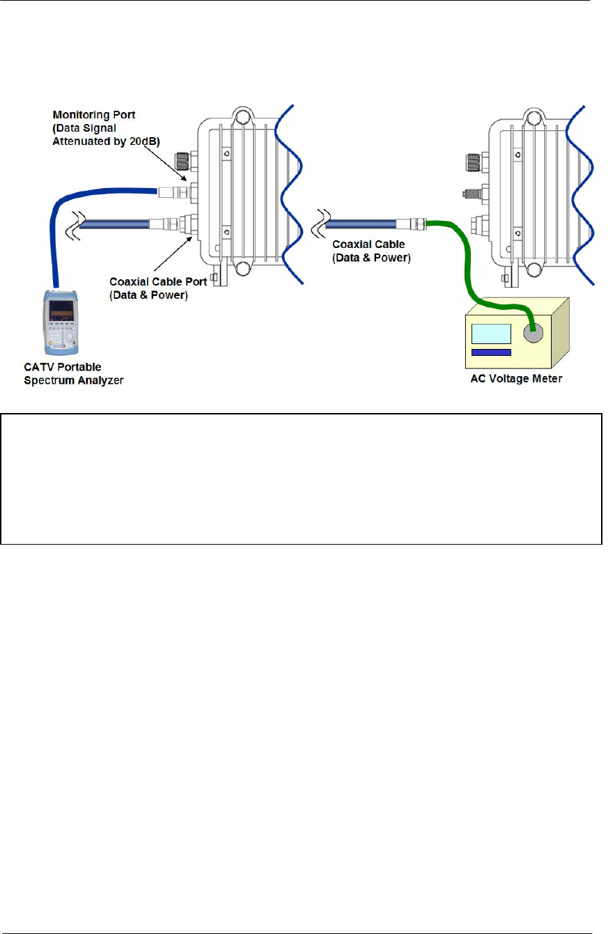
1. Connect an actual coaxial cable to the coaxial port on the APU.
2. Connect a measurement coaxial cable to the monitoring port on the
APU.
3. Measure the Signal Power level at monitoring port.
Note: In case of installation using a Trunk or Distribution Cable &
Connector, it is crucially recommended to measure the RF Signal level
directly at the termination of the coaxial cable from CATV AMP(TBA)
or Splitter before connecting to APU in order to ensure a perfect
operation of Cable Modem inside APU.
If the measured Signal level is outside from the allowed range referred in
DOCSIS, you should adjust the AMP Power level or perform another
proper tuning method to meet the requirement of RF signal level.
It is also recommended to measure AC voltage from CATV UPS Power
Supply to ensure a perfect operation.
Note: In case of installation using a Drop Cable, it is recommended to
measure the AC voltage from Local CATV Power Supply to ensure a
perfect operation. But if you can confirm that a power supply facility is
compliant to the power requirement of APU, this step can be skipped
4. Check if the acquired power level converted by adding 20dBmV to
monitored value satisfy the range (-15dBmV ~ +15dBmV) referred
in DOCSIS standard. But, some level margin should be added to the
measured power level by 1 ~ 3 dB.
52
WLAN Cable Access Point 6220 NTPM99CA Rel 1.0 Issue 2 Nov 2004
Figure 3-25
Measuring the Power Level at the Monitoring Port
Acceptable Signal Levels
HFC Signal level (DOCSIS 1.1 ~ 2.0 Standard)
+ Standard Signal level (Actual Value): - 15dBmV ~ 15dBmV
+ Calculated Signal level at Monitoring Port (Downstream): - 35dBmV ~ -5dBmV
+ Effective Signal level at Monitoring Port (Downstream): - 37dBmV ~ -7dBmV
HFC AC Power level (Square wave): 45 VAC ~ 95VAC (Recommended level: 63Vac)

53
WLAN Cable Access Point 6220 NTPM99CA Rel 1.0 Issue 2 Nov 2004
Procedure 1-7
Power ON and Visual Checking the LED Operation
Action
Step Action
1. Ensure that you know what each one of LED Lights means for the
unit. Please refer to the LED indicators page.
2. Turn ON the HFC Power Supply.
3. Check if the LED operation follows the pre-defined steps during and
after booting.
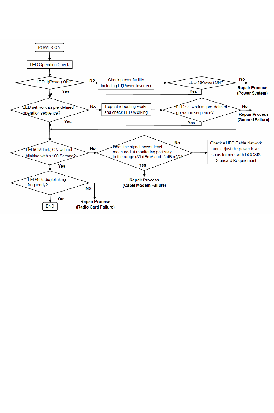
4. Refer to the System Failure Analysis Procedure on the next page
5. Check if the LED 1(Power) is ON.
Note: If there is no LED light, check if the power supply which provides
the CATV (HFC) network with AC power (45 ~ 95VAC) signal is
working properly and that the CATV power is detected at the end of the
coaxial cable. (If any problem has been found in the power system, the
unit has to be entered into a Repair Process)
6. Check if LED 2 (CM Link) flashes for over 100 seconds from when
power is first supplied.
If the LED flashes for more than 100 seconds, check if the data signal
level at the monitoring port on the APU meets the recommended
range of the signal level.
54
WLAN Cable Access Point 6220 NTPM99CA Rel 1.0 Issue 2 Nov 2004
Figure 3-26
LED Visual Checking Procedure
55
WLAN Cable Access Point 6220 NTPM99CA Rel 1.0 Issue 2 Nov 2004
CSU Installation & Configuration
Mounting and Installation Concept
Figure 3-27
CSU Installation Concept on User’s facility
By default, CSU is pole mounted. Each unit is shipped with a pole
mounting module.
ENSURE THE CSU HAS BEEN POSITIONED NO LESS THAN 3 FEET ABOVE
THE GROUND, OR FROM A ROUGHLY HORIZONTAL SURFACE.
56
WLAN Cable Access Point 6220 NTPM99CA Rel 1.0 Issue 2 Nov 2004
Procedure 2-1
Mounting the CSU on the Steel Wire Strand
Action
Step Action
1. Prior to an installation, check if the Pole has the strength and stability
to sustain the weight of the CSU in a strong wind
2. Please find a mounting tool for installing CSU illustrated in Figure
3-26
3. Place the CSU face (RADOME side) down on a flat surface.
4. Using the mounting tool, attach the Mounting Tilt Brackets to the
back of the CSU and insert the two stainless steel M6 hex head
screws and M6 split lock washers into the hole.
Figure 3-28
Assembling the mounting bracket on the CSU
5. Lift the CSU to the selected installation point on the pole and then
attach the clamp to the original location while lashing the CSU to the
pole or using a hoisting rope to keep the unit in place during
mounting work.
6. Slide two mounting nuts through a washer to each bracket hole as
illustrated in Figure 3-27
57
WLAN Cable Access Point 6220 NTPM99CA Rel 1.0 Issue 2 Nov 2004
7. Adjust the direction of CSU Antenna RADOME toward APU and
fasten sufficiently to secure the CSU on the pole.
Figure 3-29
Assembling the mounting bracket with a installation tool
8. Adjust the up/down tilt (- 50 º to 50 º) and move the top or bottom of
the CSU until the unit is roughly positioned at the correct angle and
height.
Figure 3-30
CSU Pole Mounting and Antenna Tilting
100
º
58
WLAN Cable Access Point 6220 NTPM99CA Rel 1.0 Issue 2 Nov 2004
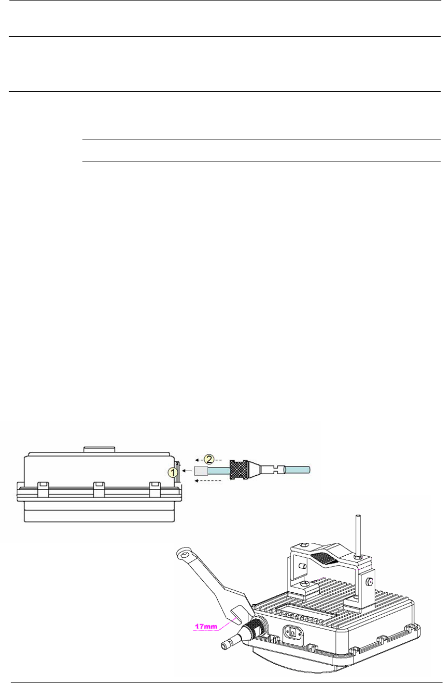
Procedure 2-2
Mounting the CSU on the Steel Wire Strand
Action
Step Action
1. Loosen the EMI cap and slide the CAT5 or 6 cables without the RJ45
connector into the hole of the EMI hood shaped cap.
2. Follow the conventional procedure of creating a CAT5 or 6 Ethernet
cable.
Note: It is recommended to use a shielded cable like S-FTP(Foiled
Twisted Pair) or STP (Shielded Twisted Pair) in which wire pairs are
covered with overall shield material to prevent EMI effects to or from the
near electronic devices or facilities.
Note: The cable from CSU to POE Injector and from POE Injector to
CPE (PC) should be a straight-through cable.
3. Connect a cable to the CSU’s POE port through the hole of EMI cap
and tighten it firmly.
Figure 3-31
Connecting Ethernet Cable to CSU and Securing the Port Cap.
59
WLAN Cable Access Point 6220 NTPM99CA Rel 1.0 Issue 2 Nov 2004
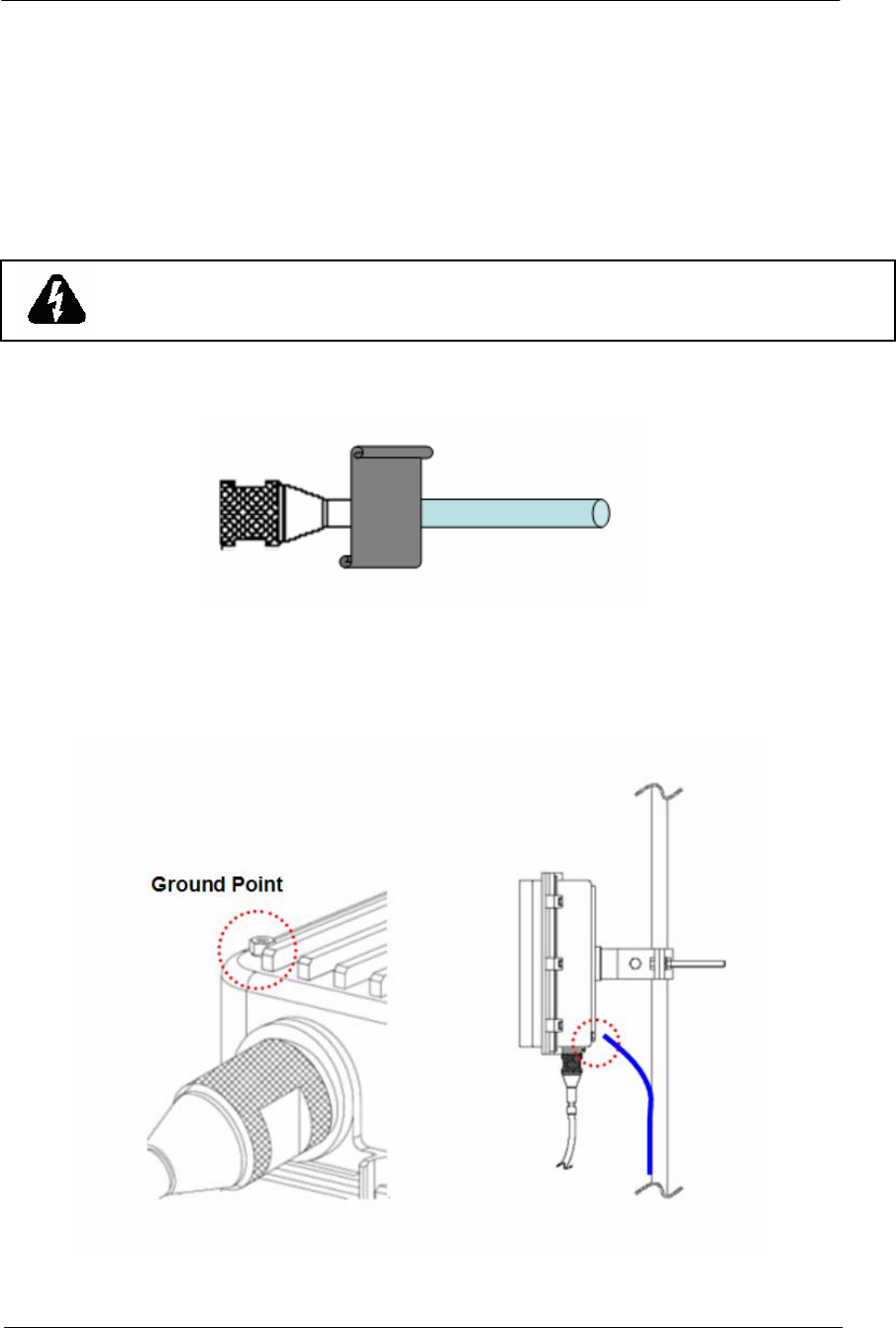
4. Secure the cable in the EMI cap by tightening it with a cable tie.
Cover the connectors with black self amalgamating tape or shrink
wrap tubing to ensure a waterproof seal. This is the most crucial step
of the installation. If this procedure is not completed, long-term and
complex problems could occur.
5. Tighten the EMI cap securely with the special tool including the
product package.
Figure 3-32
Cover the EMI Cap and Shielded Cable with Tape or shrink wrap tubing
6. Connect the ground wire to the ground point at the lower right end of
CSU back panel.
Figure 3-33
Connecting the ground wire to the ground point
7. Connect the other end of the data cable to the POE Injector indoor.
8. Plug the power cord of the POE Injector into an electrical outlet
WHEN INSTALLING THE UNIT, CHOOSE A LOCATION THAT PROVIDES A
MINIMUM SEPARATION OF 20 cm FROM ALL PERSONS DURING NORMAL
OPERATION.
60
WLAN Cable Access Point 6220 NTPM99CA Rel 1.0 Issue 2 Nov 2004
Figure 3-34
Connecting CSU and User PC by an Ethernet Cable though POE Injector
Mounting Tips
• Verify the Line-of-Sight -- Before installing the CSU, make sure a clear line-
of-sight exists. Line of sight (LOS) can be defined as each antenna clearly
seeing the other antenna, and seeing the remote locations when viewing from
the central base location. Be sure to look level with the center of origin of the
transmission (i.e., the middle of the antenna). Repeat this procedure from the
remote location. Any disruption of the signal path due to trees, buildings, or
any other obstructions may cause the link to function incorrectly. If you see
any obstructions between two antennas, move one or both antennas to
another location.
• Use mounting hardware provided to secure the unit to the pole.
• Leave the unit mounting loose enough to allow for movement when
performing the alignment/testing procedure. The unit should be tightened
only after the alignment/testing procedure is completed.
• Install the unit away from microwave ovens and 2.4 GHz cordless phones.
Microwave ovens and some cordless phones operate on the same frequency
as the unit and can cause signal interference.
• Begin at the lowest point, so the tape overlaps from bottom to top creating a
shingled effect. This creates an effective barrier against water runoff. Apply
this "shingle effect" to each layer of the sealing process. Apply two layers of
electrical tape to the connector, and leave approximately 3 inches of cable
exposed on either side of the connector.

61
Configuration
WLAN Cable Access Point 6220 (APU, CSU) has the following
management and operational features listed below:
Software Installation
APU Basic Configuration and Operation Test
CSU Basic Configuration and Operation Test
Testing the connection between APU and CSU
Testing Wireless Network Performance
Basic Configuration
Advanced and Optional Configuration

62
WLAN Cable Access Point 6220 NTPM99CA Rel 1.0 Issue 2 Nov 2004
Software Installation (AP Configurator)
The WLAN Cable AP Configurator is used to configure your wireless
networking devices. Both the executable file needed to install the
Configurator and the online help for the Configurator (*.chm) are
included on the Software CD that you received with your hardware
device. Refer to the online help or the WLAN Cable AP Configuration
User Guide on the Document CD for detailed instructions on how to
configure your device. This section explains the system configuration in
detail.
Note: The features available to you in the WLAN Cable AP
Configuration vary depending on the version of the software. This
section explains all possible features involved in basic configuration.
Your actual software may not display all of the features and fields
described.
Installing the Configurator Software
1. Insert the Software CD into your PC’s/laptop’s CD ROM drive, then
you can see the installation web page as below.
Figure 4-1
Software CD Starting Display
2. Click the “Install” button and press the “open” button to find the
dialog box.
3. Double click the name of the Configurator Installation program
(the .exe file on your Software CD).
63
WLAN Cable Access Point 6220 NTPM99CA Rel 1.0 Issue 2 Nov 2004
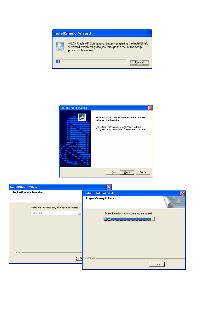
Figure 4-2
Software Installation Launching
3. Follow the onscreen instructions to install the Configurator.
Figure 4-3
Installation Dialog Window
If you are installing the Configurator for the first time, files are stored in the
directory Program Files/Nortel/WLAN Cable AP Configurator. If you are
upgrading from a previous Configurator installation, your files will be stored
in the directory where you last saved the Configurator files. The Install
Shield also installs shortcuts to the Configurator on your desktop.

64
WLAN Cable Access Point 6220 NTPM99CA Rel 1.0 Issue 2 Nov 2004
Procedure 3-1
APU Basic configuration and Operation Test
Action
Step Action
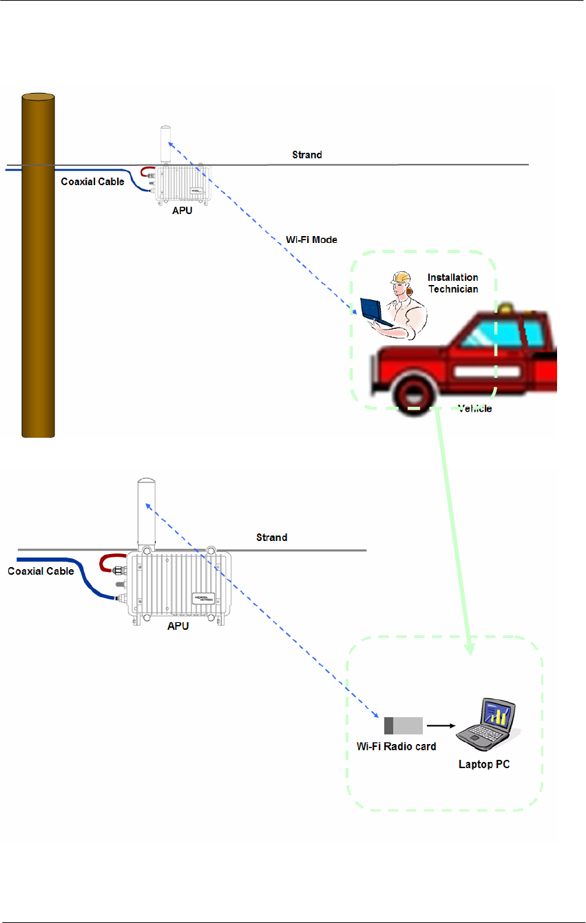
1. Prepare a Laptop computer and a client unit to test and configure the
APU at the installation field.
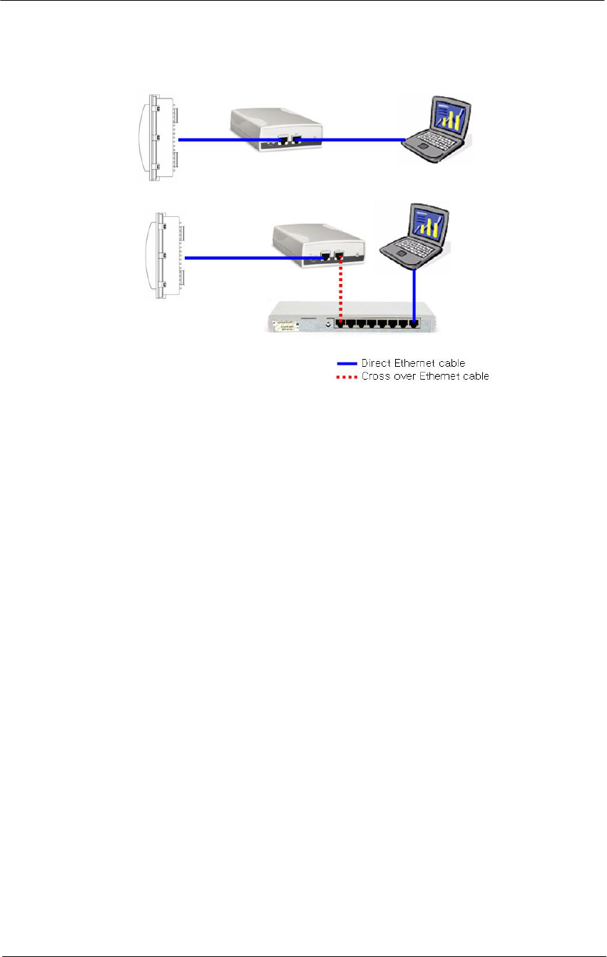
2. There are two kinds of test setups between APU and Wi-Fi Radio
card as below.
A. Type I (Radio Connection: Primary)
This type of test setup is very simple and reliable to setup and test
the operation of APU without additional accessories except
PCMCIA type radio card.
The APU operation test can be performed with only a radio
connection between the APU antenna and Wi-Fi Radio Card in
Laptop PC as shown in Figure 4.4.
B. Type II (RF Cable Connection: Secondary)
If a more secure and reliable setup is required. The APU
operation test can be performed using an RF cable, between the
APU antenna and the Wi-Fi Radio Card in the Laptop PC.
This type of test setup may be a little cumbersome, but, it allows
checking the APU operation and configuration in a secure
environment which will exclude interference from neighboring
radio devices.
Please ensure that each cable has a different termination type at
each end (APU side: N type Male, Radio card side: PC card)
3. The APU has the following factory default parameters:
Factory Default
IP address: DHCP Client (Ethernet 1)
Read Write Password: public
SNMP Secure Configuration Password: public
IEEE 802.11 Interface Setup
- Mode Selection: 802.11 compatible Access Point Mode
- Frequency: CH1 (2412 MHz)
- Transmit Rate: 11Mbps
- SSID: WLAN Cable AP
- WEP Encryption: Disable
65
WLAN Cable Access Point 6220 NTPM99CA Rel 1.0 Issue 2 Nov 2004
Figure 4-4
Test Network Configuration (Radio Connection)
4. Using a laptop computer, search the APU by scanning its’ default
SSID “WLAN Cable AP” and connect to the entity and check if the
radio signal shows a good performance.
66
WLAN Cable Access Point 6220 NTPM99CA Rel 1.0 Issue 2 Nov 2004
5. Launch the Configurator by either double clicking the WLAN Cable
AP Configurator icon on your desktop or by opening the file
config.exe from the directory “C:\Program Files\Nortel\WLAN
Cable AP Configurator” where software is installed
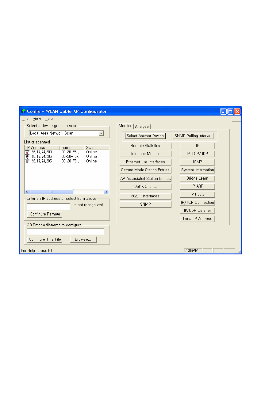
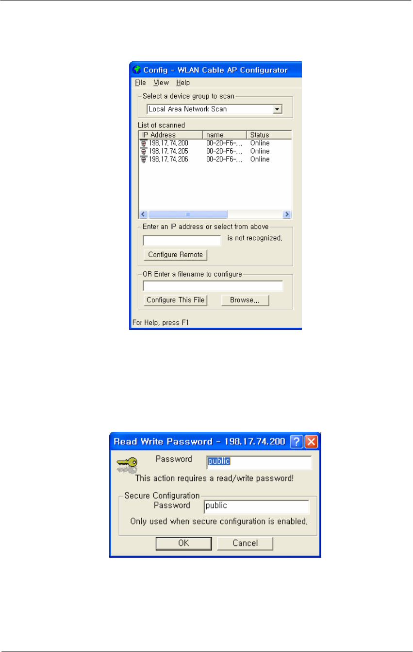
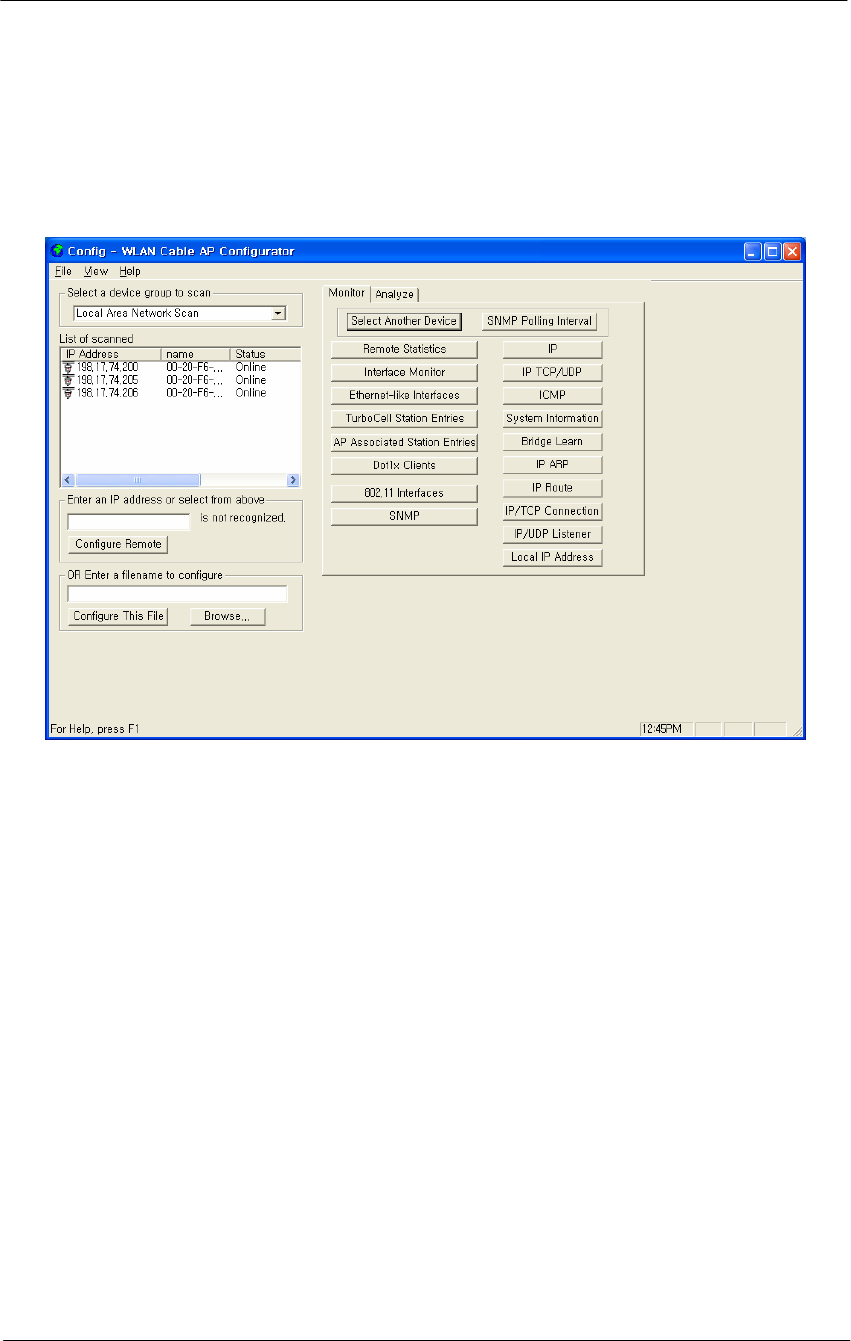
6. Run the Configurator and the IP Address for your APU (and the IP
addresses for any other devices in your network) as appears in the
Configurator window below.
Figure 4-5
Configurator Starting Window
7. Ensure that the laptop computer gets an IP address from the DHCP
server at Network Center by checking an IP address list box at the
left side of the configurator window.
8. If the APU you wish to configure is on the same network subnet as
your computer, you can select it from the list that is automatically
displayed in the IP Address window. Press the <F5> key to refresh
the scan list. Alternately, you can also right click anywhere in the
scan window and select Re-scan the local network.
Note: To differentiate the APU to be configured, you should check the
AP MAC address of the APU which is printed on the label attached on
the side of the APU.
9. If you can find out the IP address of the APU on the IP address
window, move the cursor to the appropriate IP address.
67
WLAN Cable Access Point 6220 NTPM99CA Rel 1.0 Issue 2 Nov 2004
Figure 4-6
IP address list box
10. Right click on the IP address, and click the Configure button below
the list box on the left side of the configurator window. The
Read/Write Password screen is displayed, as shown below.
Figure 4-7
SNMP Password (Read/Write)
11. Enter the password “public” for the device you have selected in both
text boxes, and then click the OK button.
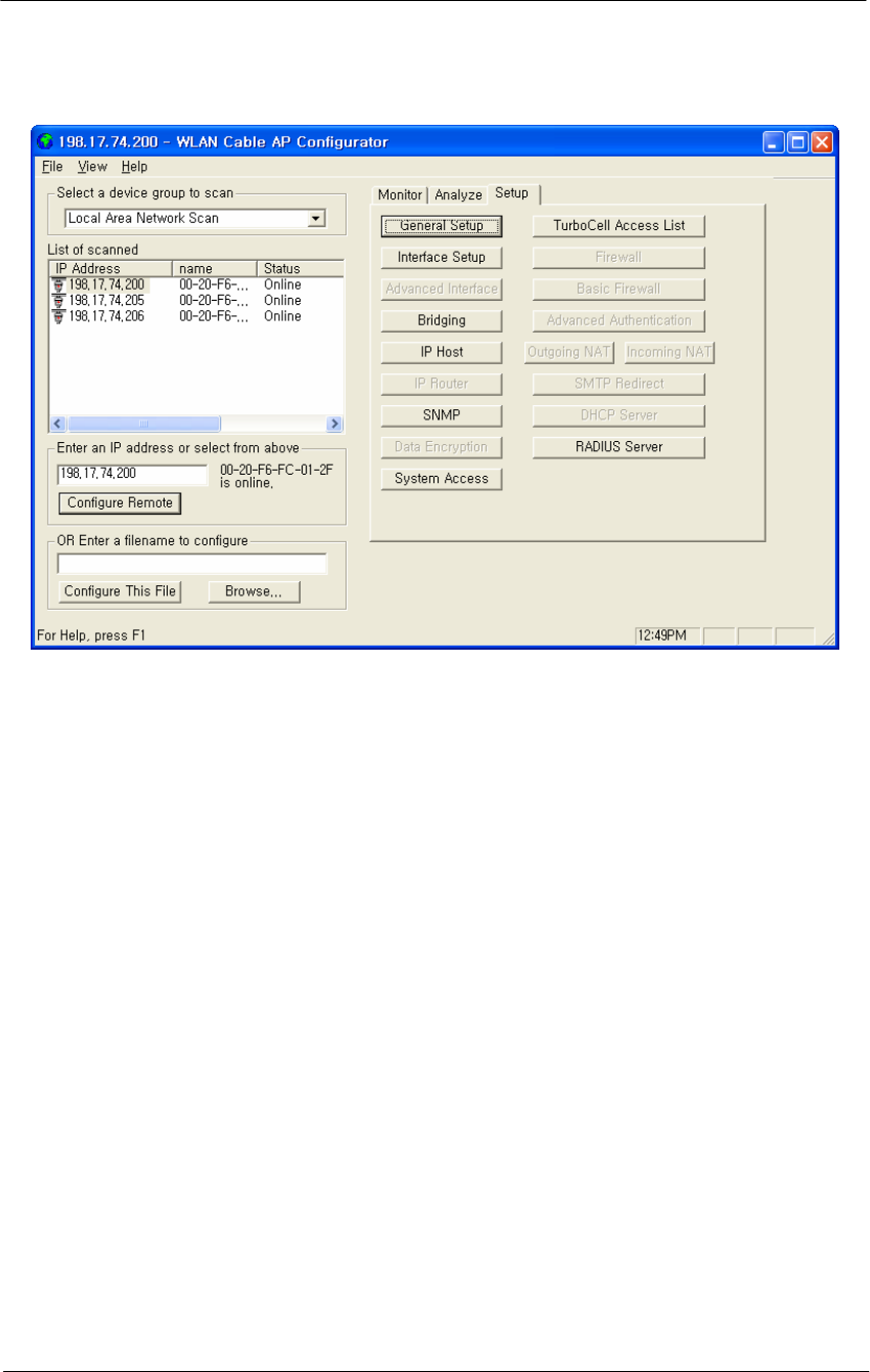
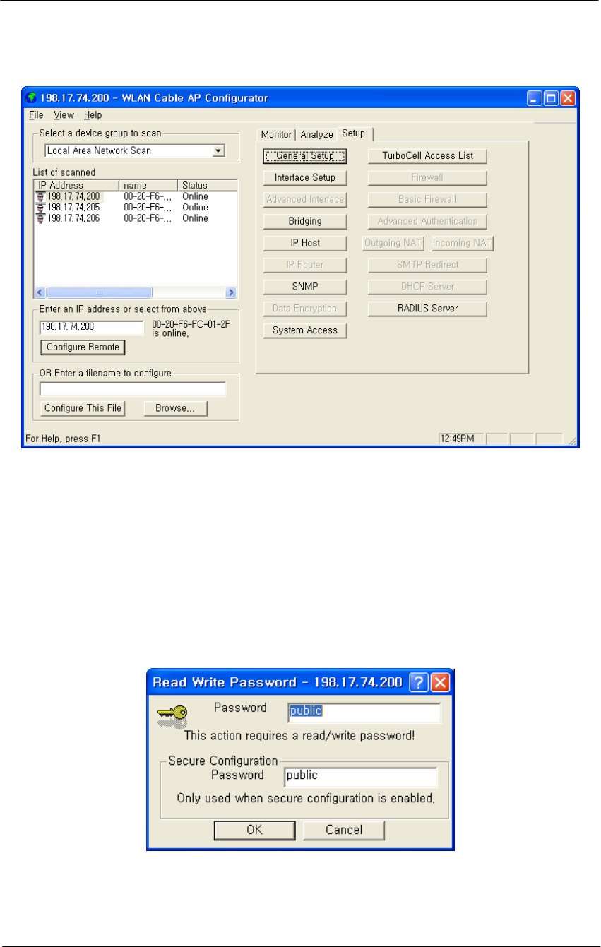
12. If the Setup tab is displayed in the main window as shown below,
SNMP checking is a success.
68
WLAN Cable Access Point 6220 NTPM99CA Rel 1.0 Issue 2 Nov 2004
Figure 4-8
Setup Tab
Note: When you test the APU with Test CSU, you don’t have to change
the parameters of the APU with the AP configurator. But, after all tests
are completed, you should configure the APU according to your local
network design idea.
13. Perform Ping Test to the specific IP address of network entity which
is located at the public internet network during the defined minutes
(1 ~ 2 minutes)
14. Click the Start Button at the left corner of the screen and the Run
button.
15. Enter the command “cmd” to find out the “DOS Command window”
16. Enter the ping command “ping –t < Destination IP address > “
17. You can see the Ping response from the destination.
18. After the defined ending time, press Ctrl + “C” and record the Ping
response.
19. Perform the FTP Download/Upload Test with the Test server through
the Network Center or verify this functionality by accessing any
commercial website with a web browser using the test laptop PC.
20. Configure the APU with your final setup parameters for one or both
operation modes as Wi-Fi or Secure Data Mode (APU).
21. For a more detailed setup, refer to the procedure 3-5(Basic
Configuration) and 3-6(Advanced and Optional Configuration).
69
WLAN Cable Access Point 6220 NTPM99CA Rel 1.0 Issue 2 Nov 2004
Procedure 3-2
CSU Basic configuration and Operation Test
Action
Step Action
1. Connect the Ethernet cable (straight) between the Laptop PC and
CSU via POE Injector.
2. Launch the Configurator by either double clicking the WLAN Cable
AP Configurator icon on your desktop or by opening the file
config.exe from the directory “C:\Program Files\Nortel\WLAN
Cable AP Configurator” where software is installed.
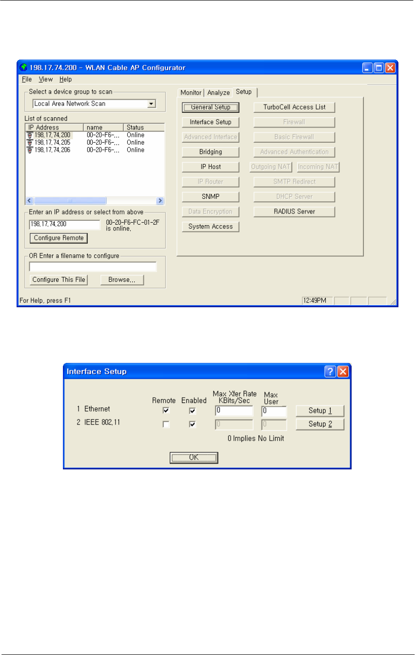
3. The Configurator will open and the IP Address for your APU and
Test CSU (and the IP addresses for any other devices in your
network) will appear in the Configurator window as shown below.
Figure 4-9
Configurator Starting Window
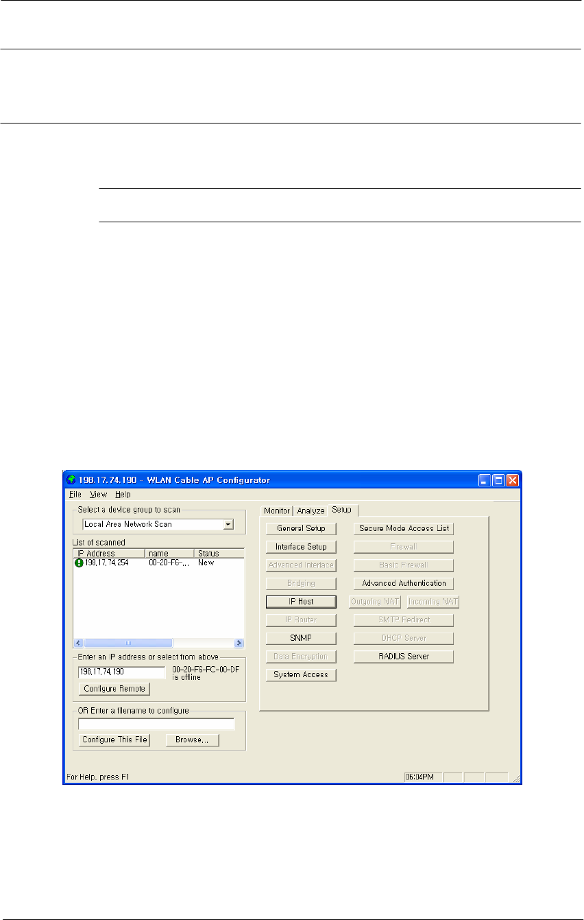
4. Note the device in the List of Scanned Devices window showing the
green exclamation point”198.17.74.254”. This is the device (CSU)
you need to configure. Right click on this device, and then select
‘Configure This Device’. The Change IP window is displayed, as
shown in the following screenshot.
70
WLAN Cable Access Point 6220 NTPM99CA Rel 1.0 Issue 2 Nov 2004
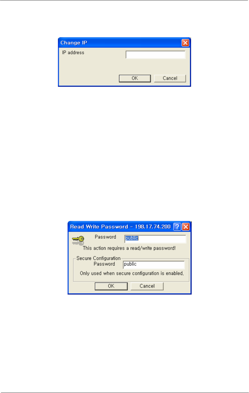
Figure 4-10
IP setup dialog box
5. Enter an IP address that will be local to the IP of the PC/laptop
running the Configurator, and then click the OK button. The main
window is redisplayed.
For example, in case the IP address of Laptop computer is
192.168.0.100/24, the CSU will be allowable in 192.168.0.1/24 ~
192.168.0.254/24 as the IP address subnet group.
Note: The IP address to enter should be included in the same subnet area
with PC/Laptop Computer for access to CSU.
6. The SNMP Password dialog box is displayed, as shown below.
Figure 4-11
SNMP Read Write Password dialog box
7. Enter a proper password in the basic SNMP password box.
8. Click the OK button.
9. The Interface Setup screen is enabled and displayed, as shown in the
Figure 4-12
10. Click the Interface Setup button. The Interface Setup screen is
displayed, as shown in Figure 4-13. And you do not need to set up
the Ethernet Interface.
11. If you have an 802.11b radio card, click the Setup 2 button to set up
the 802.11b interface.
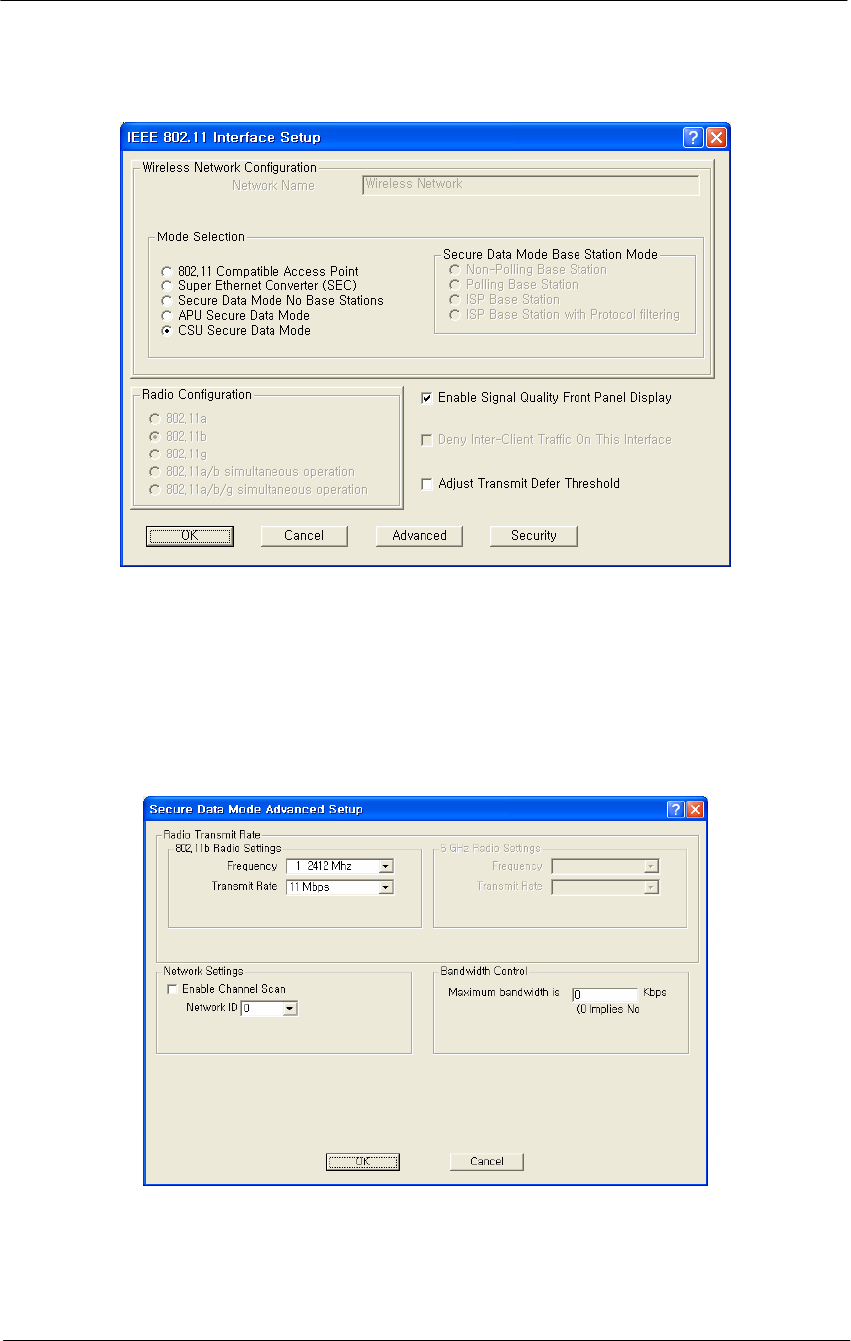
12. Click the Setup 2 button. The IEEE 802.11 Setup screen is
displayed, as shown in Figure 4-14.
71
WLAN Cable Access Point 6220 NTPM99CA Rel 1.0 Issue 2 Nov 2004
Figure 4-12
AP Configurator Main window
Figure 4-13
Interface setup dialog box
13. Make sure the CSU Secure Data Mode in the left portion of Mode
Selection is selected.
14. Select the Enable Signal Quality Front Panel Display checkbox if
your unit has a front panel display that is capable of displaying the
signal quality.
72
WLAN Cable Access Point 6220 NTPM99CA Rel 1.0 Issue 2 Nov 2004
Figure 4-14
Interface setup dialog box
15. Click the Advanced button to set up crucial parameters such as Radio
Frequency, Transmit Rate (Bandwidth) and Network ID.
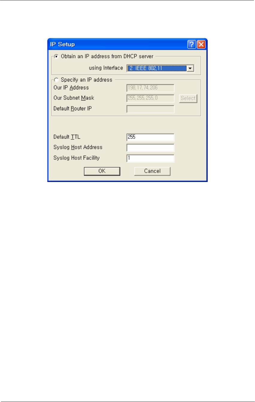
16. The 802.11b Advanced Setup screen for a Secure Data Mode is
shown below.
Figure 4-15
Advanced setup dialog box
17. Select the Frequency and Transmit Rate in 802.11b Radio Setting.
18. Select the Network ID in Network Settings.
19. In case you only know the Network ID, enable the auto channel scan
by checking the checkbox in the networks setting box.

73
WLAN Cable Access Point 6220 NTPM99CA Rel 1.0 Issue 2 Nov 2004
20. Please see appendix G “Wireless Network Planning”.
Note: the Secure Data Mode network ID number (0-15) is used to
differentiate between multiple Secure Data Mode stations using the same
System Access Pass Phrase. This is used to allow a Secure Data Mode
CSU to specify the APU that it wants to connect to if two APUs can be
seen by the same CSU. Generally, this value should be the same as the
Channel Number.
Note: The Radio Transmit Rate should be chosen from the following list
while considering the service level of the user.
Auto-select (IEEE 802.11 only)
Low (1 Mbps)
Standard (2 Mbps)
Medium (5.5 Mbps)
High (11 Mbps)
Note: The channel/frequency values are usually determined by network
administrators. If you set the channel and frequency, ensure that there
are at least four numerical channel differences between two overlapping
cells to avoid interference. For example, channels 1, 6 and 11 don’t
overlap, but channels 1 and 3 do.
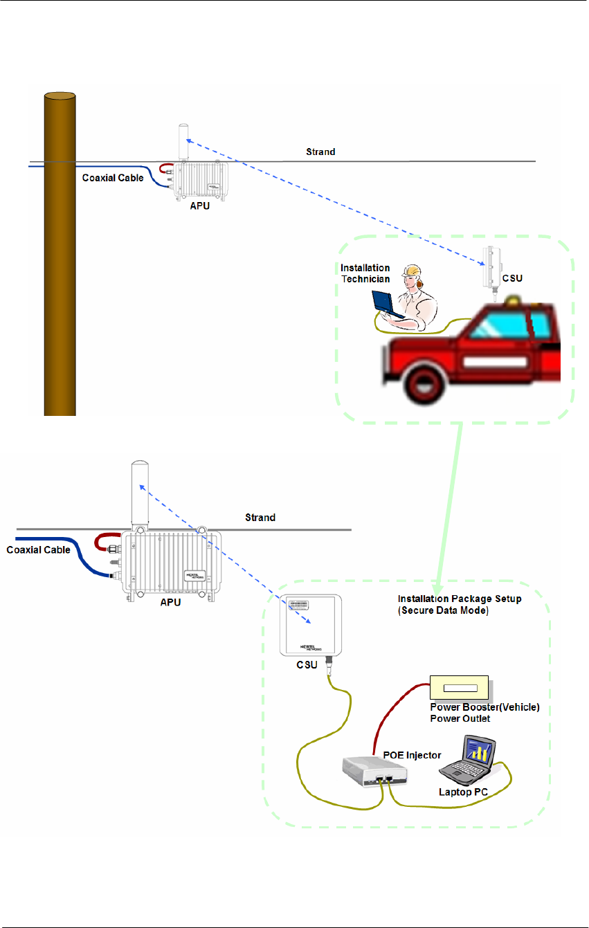
21. Click the Setup Æ IP Setup button. The IP Setup screen is displayed,
as shown below.
Note: The IP Setup screen allows you to set the Secure Data Mode
Station's IP Addressing information. The Secure Data Mode Station must
have an IP address assigned to it if you wish to connect to it using the
Configurator tool, which makes use of SNMP to connect to the Secure
Data Mode Station.
22. Select “2 IEEE 802.11” as the interface which is used to get DHCP
IP address from DHCP Server.
Note: You can choose to set up the APU to obtain an IP address from
DHCP server. If you select this option, you must also choose the
interface on which you would like the APU to send the request. This
option causes your APU to send a broadcast request for its IP address,
subnet mask, and default router over the given interface at APU startup
time. If you select the DHCP option, it is recommended (though not
required) that you set up your DHCP server to always provide the same
IP address to this Secure Data Mode Station system.
23. For a more detailed setup, refer to the procedure 3-5(Basic
Configuration) and 3-6(Advanced and Optional Configuration).
74
WLAN Cable Access Point 6220 NTPM99CA Rel 1.0 Issue 2 Nov 2004
Figure 4-16
IP setup dialog box

75
WLAN Cable Access Point 6220 NTPM99CA Rel 1.0 Issue 2 Nov 2004
Procedure 3-3
Testing the connection between APU and CSU
The Configurators’ Wireless Link Test screen is used to diagnose the
wireless link quality between your APU and any CSU associated with
the APU.
The Wireless Link Test displays the diagnostic counters that apply to the
radio interface and a single remote station connected to this APU.
To assess the overall wireless performance in the wireless area served by
the APU, you might need to run Remote Link Tests with multiple CSUs
(one by one).
Action
Step Action
1. Prepare a Laptop computer and configure the test network as shown
in Figure 4-17.
2. Prepare a CSU module, POE Injector and Power supply system like a
Power booster in a vehicle or regular power outlet in the home.
Note: Ensure that the CSU and the Laptop computer are set to DHCP
Client so that they can get the IP address dynamically through the APU
from the Server.
3. The CSU has the same system parameters as the APU. Set the system
parameter as follows to test connection.
Table 4-1
System Main Parameters
Parameter APU CSU
IP address DHCP Client DHCP Client
Read Write Password User-specific User-specific
SNMP Secure
Configuration Password User-specific User-specific
Mode Selection APU Secure Data Mode CSU Secure Data Mode
Base Station Mode Polling(Primary) N/A
Frequency User-specific Auto scanning support
Transmit Rate User-specific User-specific
Network ID User-specific User-specific
Others User-specific User-specific
76
WLAN Cable Access Point 6220 NTPM99CA Rel 1.0 Issue 2 Nov 2004
Figure 4-17
Test Network Configuration (Maintenance & Testing Setup)
4. Launch the Configurator by either double clicking the WLAN Cable
AP Configurator icon on your desktop or by opening the file
config.exe from the directory “C:\Program Files\Nortel\WLAN
Cable AP Configurator” where software is installed.
77
WLAN Cable Access Point 6220 NTPM99CA Rel 1.0 Issue 2 Nov 2004
5. The Configurator runs the IP Address for your APU and the Test
CSU (and the IP addresses for any other devices in your network)
appears in the Configurator window, as shown below.
Figure 4-18
Configurator Starting Window
6. Ensure that the laptop computer gets an IP address from the DHCP
server at Network Center by checking an IP address list box at the
left side of the configurator window.
7. Check if a Dynamic IP address is allocated to APU and Test CSU.
8. If the APU you wish to configure is on the same network subnet as
your computer, you can select it from the list that is automatically
displayed in the IP Address window. Press the <F5> key to refresh
the scan list. Alternately, you can also right click anywhere in the
scan window and select Re-scan the local network.
Note: To differentiate the APU to be configured, you should check the
AP MAC address of the APU which is printed on the label attached to
the side of the APU.
9. If you can find out the IP address of the APU on the IP address
window, move the cursor to the appropriate IP address.

78
WLAN Cable Access Point 6220 NTPM99CA Rel 1.0 Issue 2 Nov 2004
Figure 4-19
IP address list box
10. Right click on the IP address, and click the Configure button below
the list box on the left side of a configurator window. The
Read/Write Password screen is displayed, as shown below.
Figure 4-20
SNMP Password (Read/Write)
11. Enter the password “public” for the device you have selected at both
text boxes, and then click the OK button.
12. If the Setup tab is displayed in the main window as shown below,
SNMP checking is a success.
79
WLAN Cable Access Point 6220 NTPM99CA Rel 1.0 Issue 2 Nov 2004
Figure 4-21
Setup Tab
Note: When you test the APU with Test CSU, you don’t have to change
the parameters of APU with AP configurator. After all the tests are
completed, you should configure the APU according to your local
network design idea.
13. Select Wireless Link Test from the Analyze Tab. The Enter IP
Address screen is displayed, as shown below.
Figure 4-22
SNMP Password (Read/Write)
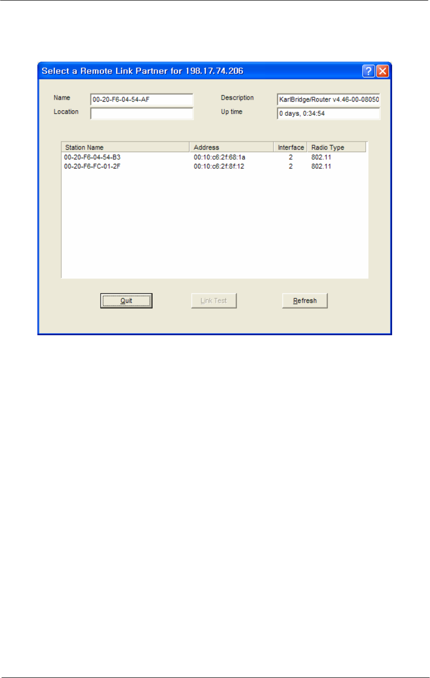
14. Enter the Remote IP Address and Read/Write password for the
wireless station you wish to test. The Select a Remote Link Partner
screen is displayed, as shown below.
80
WLAN Cable Access Point 6220 NTPM99CA Rel 1.0 Issue 2 Nov 2004
Figure 4-23
Remote Link List window
15. From the list of station names, select the remote station or client you
wish to test. Select a station from the list, and then click on the Link
Test button to perform a link test.
Note: Clicking the Explore button refreshes the list of stations that
can be selected.
16. Click the Link Test button to start the link test.
Note: When you open this screen, the base station will need
approximately 20 seconds to build the list of stations and forward this
information to your configurator station. Due to the dynamic
characteristics of mobile wireless stations, the base station will
rebuild the list of connected stations each time you select a different
station, or after clicking the Explore button. If this screen does not
display any station, there might be no wireless station up and running
in the vicinity of the selected base station.
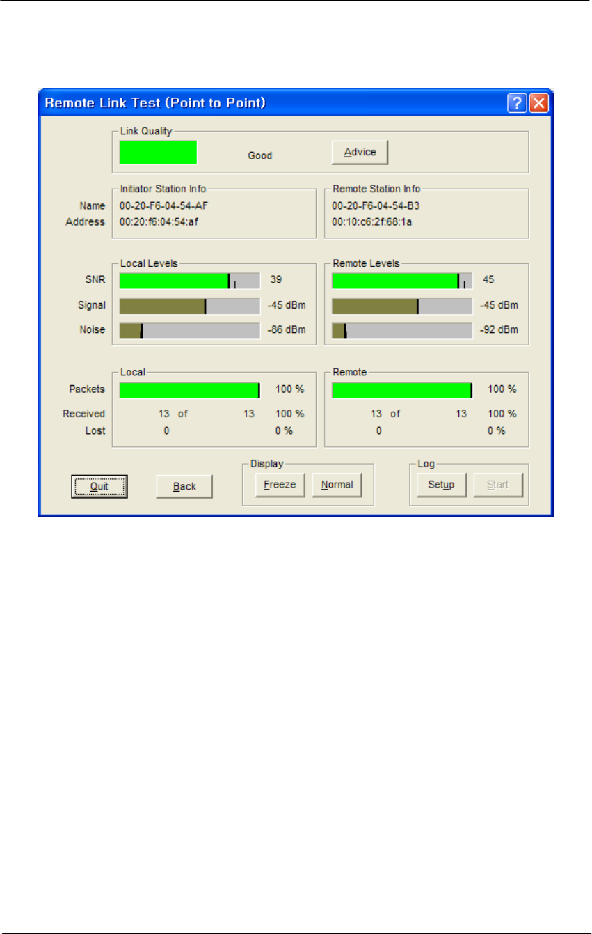
17. The Remote Link Test screen displays the results of your wireless
link test, as shown below.
81
WLAN Cable Access Point 6220 NTPM99CA Rel 1.0 Issue 2 Nov 2004
Figure 4-24
Remote Link Test Status Window
18. The advice button enables you to investigate the outcome of the
Remote Link Test assessment in more detail and provides you with
troubleshooting hints to improve the quality of the link between the
two remote nodes. The following table summarizes the possible
results of clicking the Advice button, and what action is warranted
based on the results:
19. It is necessary that you adjust the vertical tilt and horizontal angle
toward APU at the mounting point of CSU, while monitoring the RF
link quality status window so that the SNR and Link status bar for the
best quality.

82
WLAN Cable Access Point 6220 NTPM99CA Rel 1.0 Issue 2 Nov 2004
Table 4-2
Radio Link Status
Status Risk Action
Excellent None You do not need to perform further
diagnostics.
Good None You may try to optimize antenna
placement to see whether this will
improve the Link Quality result.
Marginal Communication is still
possible, but this
situation may affect the
unit's performance.
View Link Test Details to verify.
The unit may have to retransmit lost
packets.
Verify the Signal Level indicator. A
low Signal Level indicates the unit
has moved away from the base
station.
View Link Test Details to verify the
Noise Level indicator. A high Noise
Level indicates a source of
interference in the signal path
between the unit and the base
station.
Select another unit to verify if the
base station is functioning properly.
Try to optimize antenna placement
to improve the Signal Level or move
it away from the source of
interference.
“No
Connection” Communication is no
longer possible. If the
unit was in the process
of transferring files, data
may not have arrived at
the intended destination,
or it may have been
corrupted.
View Link Test Details to verify the
Signal Level indicator. A low Signal
Level indicates the unit has moved
away from the base station.
View Link Test Details to verify the
Noise Level indicator. A high Noise
Level indicates a source of
interference in the signal path
between the unit and the base
station.
Select another unit to verify if the
base station is functioning properly.
Try to optimize antenna placement
to improve the Signal Level or move
it away from the source of
interference.

83
WLAN Cable Access Point 6220 NTPM99CA Rel 1.0 Issue 2 Nov 2004
Quality
Indicator is
Black
None. The base station
may be busy collecting
diagnostic measurement
results from the unit.
If the indicator remains blank, click
the other button to return to the
Select a Remote Link Partner screen.
Click the Explore button to refresh
the list of Link Test Partners. If the
initial partner no longer appears, it
may have been switched off, or have
been moved outside the range of the
selected Initiator Station.
Select another Link Test Partner to
verify if the base station is
functioning properly.
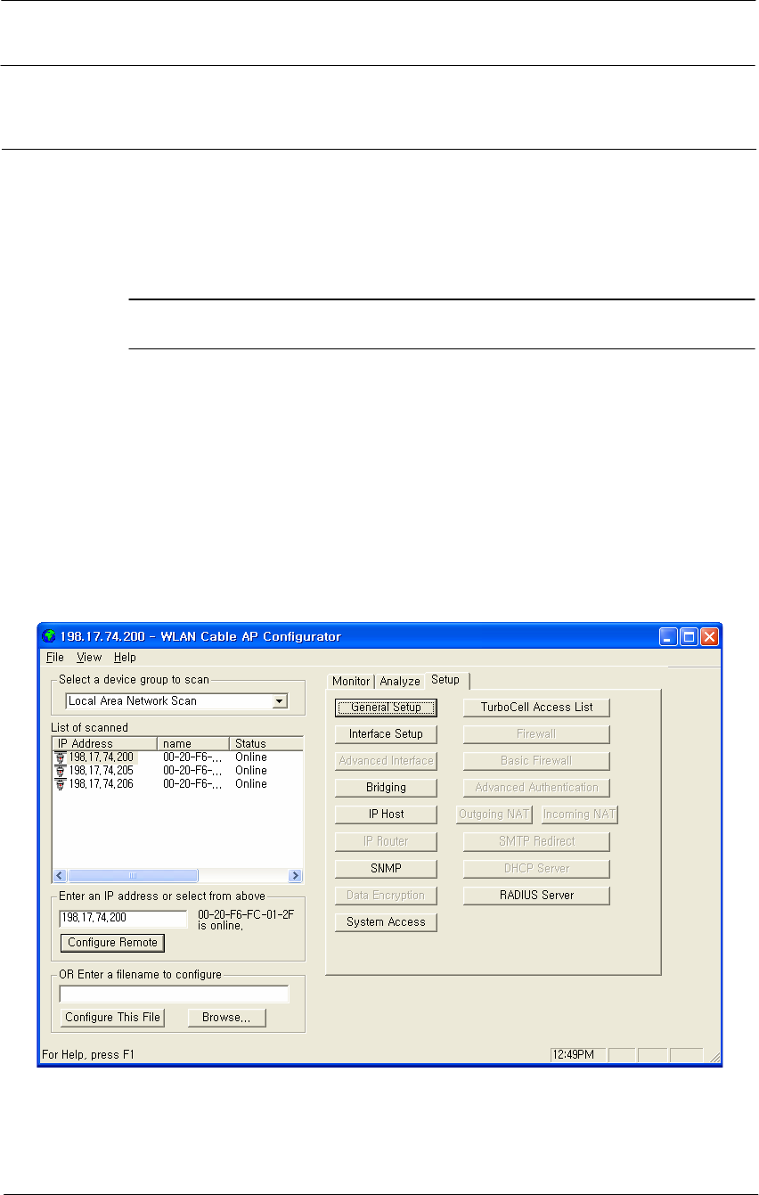
84
WLAN Cable Access Point 6220 NTPM99CA Rel 1.0 Issue 2 Nov 2004
Procedure 3-4
Testing Wireless Network Performance
FTP Up/Download Test
Action
Step Action
1. Launch the Configurator by either double clicking the WLAN Cable
AP Configurator icon in your desktop or by opening the file
config.exe from the directory “C:\Program Files\Nortel\WLAN
Cable AP Configurator” where software is installed.
2. The Configurator runs the IP Address for your APU and Test CSU
(and the IP addresses for any other devices in your network) appears
in the Configurator window.
Figure 4-25
Configurator Starting Window
3. Make sure that the laptop computer gets an IP address from the
DHCP server at Network Center by checking an IP address list box at
the left side of the configurator window.
4. Check if the Dynamic IP address is allocated at the APU.
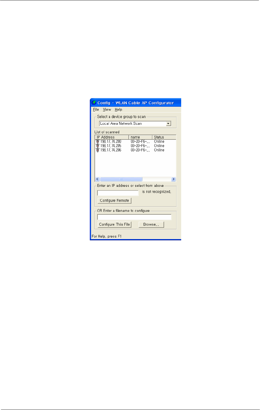
85
WLAN Cable Access Point 6220 NTPM99CA Rel 1.0 Issue 2 Nov 2004
5. If the APU you wish to configure is on the same network subnet as
your computer, you can select it from the list that is automatically
displayed in the IP Address window. Press the <F5> key to refresh
the scan list. Alternately, you can also right click anywhere in the
scan window and select Re-scan local network.
6. If you know the IP address of APU on the IP address window, move
the cursor to the IP address.
Figure 4-26
IP address list box
7. Perform a Ping Test to the specific IP address of network entity
which is located at the public internet network during the typical
minutes(1 ~ 2 minutes)
8. Click the Start Button at the left corner of windows and the Run
button.
9. Enter the command “cmd” and find out the “DOS Command
window”
10. Enter the ping command “ping –t < Destination IP address > “
11. You can see the Ping response from the destination.
12. After the defined ending time press Ctrl + “C” and record the ping
response result.
13. Perform the FTP Download/Upload Test with the Test server through
the Network Center.
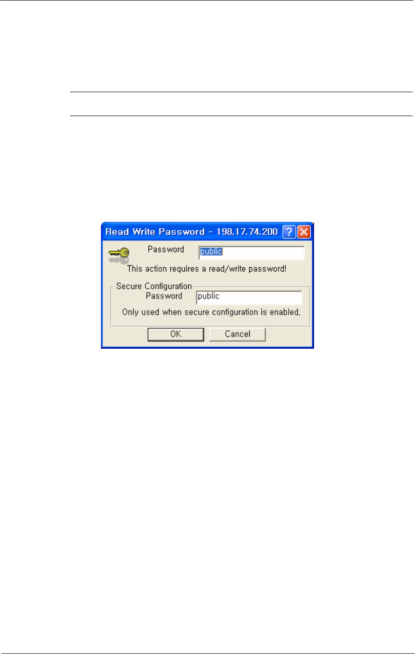
86
WLAN Cable Access Point 6220 NTPM99CA Rel 1.0 Issue 2 Nov 2004
Testing Wireless Network Performance (Ping Fill Test)
Action
Step Action
1. On the Analyze tab, click the Ping Fill Test button. The Enter IP
Address screen is displayed.
Note: The above IP address should be that of the CSU (Client of APU)
which can get the IP address list box at the AP configurator.
Figure 4-27
IP Address Tab
2. Enter the IP address and Read/Write Password of the Internet host with
which you would like to test throughput, and click the OK button. The
Ping Fill Test Parameters screen is displayed. .
Note: To test wireless performance, the target system can be one of the
APU Secure Data Mode station's clients. You can also use a wired host
to test wired interface performance.
3. Enter the Test Window Size, Max Packets, and Test Running Time.
Ex) Packet Length: 60, Window size: 80, Maximum Packets: 20,
Number of Seconds: 5
4. Click the OK button. You will see some warning messages, and then
the Ping Fill test will run. The results of the test are then displayed in
the Ping Fill Results screen.
5. Choosing the correct parameters is crucial to obtain the accurate Ping
Fill Test results. To find out more about each of the parameters, click in
the fields shown in the screenshot below.
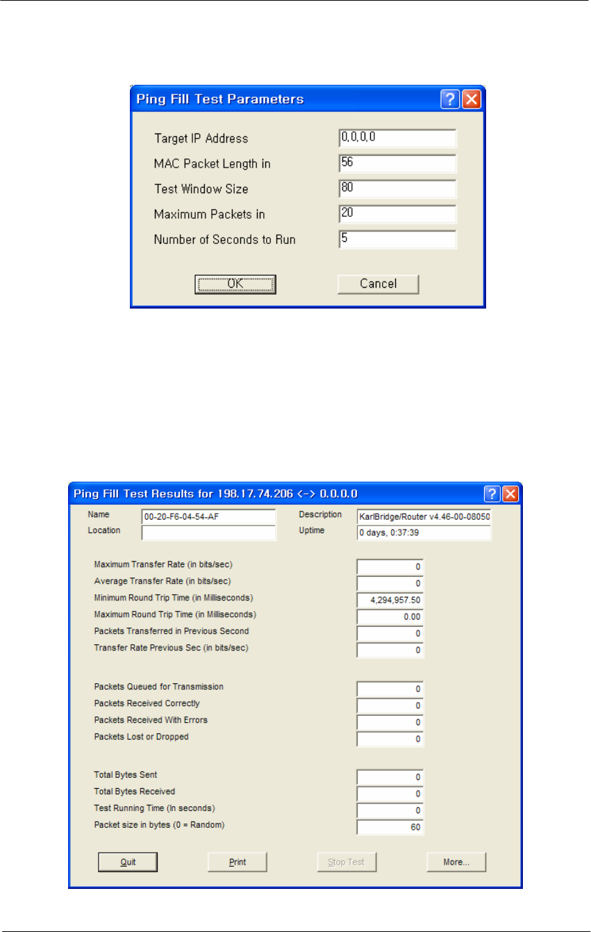
87
WLAN Cable Access Point 6220 NTPM99CA Rel 1.0 Issue 2 Nov 2004
Figure 4-28
Ping Fill Test Parameters
6. As soon as Ping Fill test is over, you can see the result windows as
below.
7. Record the results of Average Transfer Rate.
It is recommended that the results window be captured as a picture
and saved in the file.
Figure 4-29
Ping Fill Test Results Window

88
WLAN Cable Access Point 6220 NTPM99CA Rel 1.0 Issue 2 Nov 2004
Procedure 3-5
Basic Configuration
Set Up General Configuration Options
The Setup tab is used to define the configuration options for the device,
and the General Setup screen is used to enable various setup options.
Click on the Setup tab, then click the General Setup button to display the
General Setup screen as shown below:
Figure 4-30
General Setup window
Note: This menu has been modified for use in this manual. This menu
has all the supported features checked (enabled) and is NOT typical of
the menu you will see. Each of the fields on the screen is explained
below.
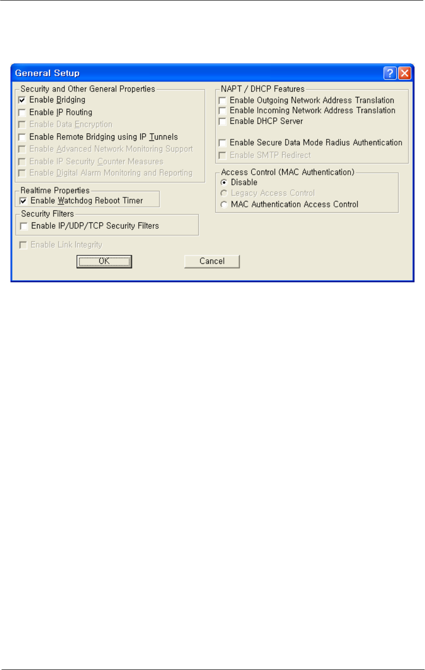
89
WLAN Cable Access Point 6220 NTPM99CA Rel 1.0 Issue 2 Nov 2004
Figure 4-31
General Setup window
Enable Bridging
Selecting this checkbox in General Setup will allow you to access the
Bridge Setup screen, which you can use to enable your device’s
transparent Ethernet bridging feature. This allows for the transference of
Ethernet packets between physical networks connected directly to the
base station.
If enabled, the base station will transfer Ethernet packets from one
interface to the other (for example, between the wireless and the wired
networks). The default behavior is to bridge all Ethernet protocols. You
can set which Ethernet protocols to bridge or deny, as well as, Ethernet
stations that will be allowed or disallowed to send packets over the
bridge using Bridge Setup from the Setup tab.
If disabled, only the IP packets with correct the IP Routes set up in the IP
Router Setup will be bridged between the base station's various
interfaces; general Ethernet packets will not be transferred across the
base station. This would be useful in a situation where you want to
enable IP traffic, but not general Ethernet traffic between (sub) networks.
Enable IP Routing
Selecting this checkbox in General Setup will enable your hardware
device to route IP packets between its various interfaces.

90
WLAN Cable Access Point 6220 NTPM99CA Rel 1.0 Issue 2 Nov 2004
If enabled, you will need to set up routes on the IP Routing screen or you
will not be able to access your hardware unit when you exit the
Configurator program.
Enable Remote Bridging Using IP Tunnels
This option allows you to encapsulate Ethernet packets of any protocol in
IP and then send them to another Secure Data Mode Bridge/Router to de-
encapsulation. Select this checkbox to enable this capability.
Some versions of the Secure Data Mode Station support a special feature
which will enable Ethernet packets of any protocol type to be
encapsulated in IP and then sent to other Secure Data Mode Stations for
de-encapsulation. This method can be used to set up "virtual" Ethernet
LANs between several points using the IP network as the transport layer.
This feature can be used to create a Virtual Private Network when used
in conjunction with the Data Encryption option.
Enable Watchdog Reboot Timer
Select this item in General Setup to enable the watchdog timer reboot
feature. If packets are not seen on the network for more than 10 minutes,
(a very rare occurrence) the Secure Data Mode Station will reboot itself.
Once it has rebooted, the 10 minute reboot timer will not activate again
until a packet has been seen on one of the interfaces. This is to ensure
that only one reboot will occur if the entire network is truly shut down.
Enable IP UDP/TCP Security Filters
Select this option in General Setup to enable the base station's Firewall
(IP Security Filter) features. You can set the base station to explicitly or
implicitly allow or deny IP connections to specific UDP or TCP ports,
and/or between specific IP addresses or subnets. For more information,
see Firewall Setup.
Note: This option is only available when the MAC Authentication
Access Control button has been selected on the General Setup screen.
Enable Outgoing Network Address Translation
Select this checkbox if you will be using Outgoing NAT to multiplex
traffic from all the computers on your internet network through the
Secure Data Mode Bridge/Router.
Outgoing Network Address Translation (NAT) allows multiple
computers to share a single IP address to connect to an IP network,
including the Internet. This allows homes, small businesses, and Internet
Service Providers to have Internet service for all of their computers
without having to pay for additional IP addresses. The NAT feature

91
WLAN Cable Access Point 6220 NTPM99CA Rel 1.0 Issue 2 Nov 2004
serves as a simple firewall for incoming connections, since only traffic
initiated by an interior computer is permitted through the NAT.
Enable Incoming Network Address Translation
Select this checkbox if you will be using Incoming NAT to multiplex
traffic from the network to all the computers on the internal network.
Incoming Network Address Translations (NAT) is used to redirect
requests to servers in the local address space based on the port of the
request. If, for example, the client at local address 10.0.1.2 is serving
web pages, and a request comes to the access point on that port for a web
session, then the request will be forwarded to the web server on 10.0.1.2.
The server will respond with the web page to the address of the original
request.
Note: Incoming NAT only needs to be configured if servers in the local
(private) Address space needs to connect with clients in the global
(public) address space.
Enable DHCP Server
Select this checkbox if you are using the Secure Data Mode Bridge/
Router to provide DHCP information to the computers on your network.
Note: If you do not check this option, you will not be able to access the
DHCP Server screen.
Enable Secure Data Mode Radius Authentication
Select this checkbox if you wish to enable RADIUS authentication for
your Secure Data Mode stations.
Enable Network Address Translation Redirector
Select this checkbox if you wish to enable network address translation
(NAT) redirection, which is used to forward the packets sent to a
particular port number to a specified IP address, regardless of the original
destination IP address.
Access Control Buttons
The access control buttons determine how authentication is controlled.
There are three possible means of authentication control:
Disable - Selecting Disable turns off MAC authentication entirely.
Legacy Access Control - Selecting Legacy Access Control enables
access to the Access Control Setup screen and disables access to the
Advanced Authentication screen
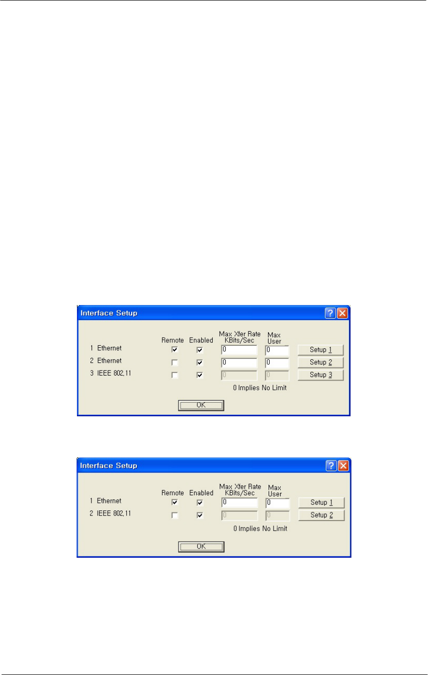
92
WLAN Cable Access Point 6220 NTPM99CA Rel 1.0 Issue 2 Nov 2004
MAC Authentication Access Control - Selecting MAC
Authentication Access Control enables access to the Advanced
Authentication Setup screen, which provides more detailed MAC
authentication setup options, and disables access to the Access
Control Setup screen.
Set Up Interfaces
Once you have enabled various configuration options, you need to define
the network interfaces for your hardware device. You will typically set
up one or more of the following interfaces:
As the name suggests, the Interface Setup screen is used to set up
network interfaces. From the Setup tab, click the Interface Setup button.
The Interface Setup screen is displayed, as shown below:
Figure 4-32
Interface setup window
Interface (APU)
Interface (CSU)
The following rules apply for setting up network interfaces:
You do not need to set up the Ethernet Interface.
If you have an 802.11b radio card, click the Setup 2 button to set up
the 802.11b interface.

93
WLAN Cable Access Point 6220 NTPM99CA Rel 1.0 Issue 2 Nov 2004
Remote Checkbox -- Select this checkbox if all traffic coming in on this
interface is to be viewed as remote traffic for firewall, bridging, filtering,
and routing purposes. If this checkbox is not selected, then all traffic on
this interface will be considered local traffic. Note that the “Remote”
designation is significant only for the Security filters, and does not imply
physical location. The security filters will pass (permit) or drop (deny)
packets of particular types from being forwarded between interfaces
designated as “Local” (unchecked) and those designated as “Remote”.
Note: At least one enabled interface must be a remote interface.
Enabled -- Select this checkbox if this interface should be enabled. If
this box is not selected, then the base station will disable the interface
and it will not be used, and the interface itself will be "down" from an
administrative standpoint.
Note: At least one enabled interface must be a remote interface.
Maximum Transfer Rate (Kbits/sec) -- The maximum transfer rate is
the number of bits that can be used for sending and receiving packets. If
you wish to limit the maximum data transfer rate for a particular
interface, enter the maximum number of kilobits per second that can be
transmitted from and to the base station. This helps to reduce the risk of
over-powering remote sites and to limit the bandwidth used by a
particular base station.
Note: The transfer rate represents the total transfer rate for both sending
and receiving packets. For example, if you set the transfer rate to 10,000
Kbits (10 Mbits) per second, then 10 Mbits represents the maximum rate
available for both sending and receiving packets. Therefore, if you use 7
Mbits per second in sending the packets, then only 3 Mbits per second
are available for receiving packets.
Setup 1, 2, 3 -- The Setup 1, 2 buttons are used to define the available
interfaces. In the screenshot shown above, clicking Setup 1 will display
the Ethernet Setup screen, clicking Setup 2 will display the 802.11b
Setup screen. Each of the Interface Setup screens is explained in more
detail below.
Set up Ethernet
Clicking the Setup 1 button on the Interface Setup screen displays the
Ethernet Setup screen.
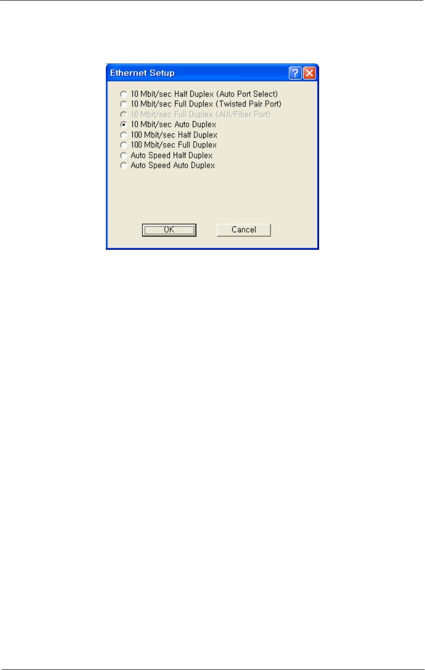
94
WLAN Cable Access Point 6220 NTPM99CA Rel 1.0 Issue 2 Nov 2004
Figure 4-33
Ethernet Setup window
The Secure Data Mode station will automatically set up the Ethernet
interface to use the type of medium that has been connected to the unit.
By default, the Ethernet connection is set at 10 Mbit/sec for both half
duplex and full duplex. Therefore, you do not need to configure special
settings for the Ethernet hardware interface. If you wish to customize the
Ethernet settings, you can change the settings listed below. However,
you do not need to change any settings for your hardware device to be
functional.
The Secure Data Mode Station supports both Ethernet IEEE 802.3
and DIX Ethernet frame types.
Protocols are set in the Interface Setup window of the Setup Tab.
Note: Do not change the default setup “10Mbit/sec Auto Duplex” in this
setup window without consulting the manufacturer.
Ethernet Type -- The Ethernet type options provide a variety of
Ethernet settings. The default value for Ethernet type will vary,
depending on your hardware device. Only the settings that are enabled
on your screen are supported by your particular hardware device. If your
switch or Ethernet card supports different speeds, you may want to
change the speed setting.
Set Up 802.11b
Clicking the Setup 2 button on the Interface Setup screen displays the
802.11b Setup screen. The 802.11b Setup screen is used to set up the
interface to your 802.11b network devices.
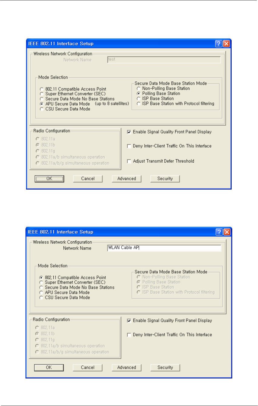
95
WLAN Cable Access Point 6220 NTPM99CA Rel 1.0 Issue 2 Nov 2004
Figure 4-34
802.11 Radio Interface Setup window (APU Secure Data Mode)
Figure 4-35
802.11 Radio Interface Setup window (APU Wi-Fi Hotspot Mode)
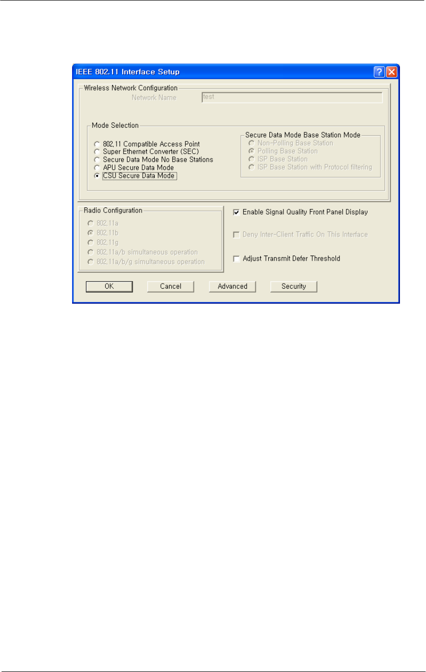
96
WLAN Cable Access Point 6220 NTPM99CA Rel 1.0 Issue 2 Nov 2004
Figure 4-36
802.11 Radio Interface Setup window (CSU)
802.11b Network Name-- The 802.11b Network Name is used in
standard IEEE 802.11b networks to distinguish stations in your 802.11b
network from stations that belong to a neighboring 802.11 network.
The value used for the radio interface on this station should be the same
for all wireless stations in the 802.11b network. Only stations configured
with the proper 802.11b Network Name will be able to connect to the
802.11b station's radio interface.
The Network Name can be any alphanumeric string in the range of "a" to
"z,” "A" to "Z" and "0" to "9,” and can contain from 1 to 32 characters.
If you wish to allow access to the wireless network to be open to all
wireless stations, the Network Name should be set to ANY.
Note: The Network Name is used only when the 802.11b radio interface
(for example, Orinoco) is set to run in IEEE 802.11 Access Point Mode.
802.11 Compatible Access Point-- When this option is selected on the
802.11a or 802.11b Setup screen, the card attached to this interface will
act as a standard 802.11a or 802.11b access point.
Use this setting when:
Connecting to any 802.11 radios acting as mobile units
Operating this interface for compatibility with other manufacturers'
access point hardware

97
WLAN Cable Access Point 6220 NTPM99CA Rel 1.0 Issue 2 Nov 2004
Communication over the wireless network is light, or is limited
primarily to one satellite
Note: When using this mode, you will not be able to connect to multiple
Access Points over the same interface.
If you wish to support a LAN (either wired or wireless) connected to the
far side of a remote 802.11 device, you must use a Secure Data Mode
Network setup by choosing one of the Secure Data Mode Station modes
(see Related Topics for more information).
The IEEE 802.11b Access Point mode is useful primarily for indoor
wireless LAN's that have no hidden nodes. For wireless network
infrastructure connections you should use one of the Secure Data Mode
Station types.
Super Ethernet Converter-- When this option is selected, the card
attached to this interface will act as a Mobile Router.
You must also uncheck the Enable Bridging checkbox in General Setup
(of the Mobile Router). An Access Point acting as an IEEE Compatible
Mobile Router will allow only IP traffic to be transmitted between the
Remote IP LAN and the Secure Data Mode Network. The remote LAN
must be using IP in order to connect to the IEEE network, but can use
additional protocols as well.
In order to bridge Ethernet traffic over the wireless network between
remote LANs, you must select one of the Secure Data Mode station types.
Secure Data Mode No Base Stations-- Select this option to set your
802.11b device's radio card on this interface to run as a Secure Data
Mode Network without a Secure Data Mode Base Station (i.e. peer-to-
peer).
Use this setting only in the rare instance when all Secure Data Mode
stations are able to "see" each other (i.e., there are no hidden nodes).
When all connected Secure Data Mode Stations are not able to "'see" one
another, this setting should not be used. In that case, you should set one
of your Secure Data Mode Station stations to Secure Data Mode Base
Station, and the others to Remote (Satellite) Secure Data Mode Stations.

98
WLAN Cable Access Point 6220 NTPM99CA Rel 1.0 Issue 2 Nov 2004
APU Secure Data Mode-- Selecting this option sets the Secure Data
Mode Station to run as a Secure Data Mode Base Station over the
802.11b device's radio interface. Every system that needs to connect to
the wireless network must be able to connect to the Secure Data Mode
Base Station.
When you select this Base Station type, you must select one of the
Protocol Filtering Modes. The Protocol Filtering Mode determines how
the base will interact with the satellite (slave) stations. Is it recommended
that you use the Enable Filters between Slaves mode.
The possible base station modes are as follows:
Non-Polling Base Station
The non-polling Secure Data Mode Base Station Mode is provided
mostly for compatibility with older Secure Data Mode Networks, but
may give increased performance over other (polling) Secure Data Mode
Base Station modes in a lightly loaded network, or in a network with
only a few satellites.
Setting a base station to non-polling mode may increase performance in
the rare case where all satellites can hear one another (i.e. there are no
hidden nodes), or when there is sporadic network use. In an environment
where most network traffic is with one satellite, and other satellites rarely
transmit data, this setting may also increase performance. However, it is
highly recommended that you select one of the polling modes.
Selecting this Secure Data Mode Base Station Mode takes full advantage
of the features of a Secure Data Mode Network.
Polling Base Station
Selecting this Secure Data Mode Base Station Mode sets the Secure Data
Mode Station to run as a Secure Data Mode Base Station which performs
a highly optimized Nortel Networks-proprietary polling of the satellite
stations for data. In the Non-Polling Base Station mode, all wireless
stations must be able to 'hear' each others' traffic, or performance may
degrade considerably (the hidden node problem). In polling mode, the
Base Station will poll each station for data, and also offer the opportunity
for 'free-for-all' sending of data at set intervals.
In conjunction with the standard features of the Secure Data Mode
Network, this Secure Data Mode Base Station Mode offers a significant
performance increase over other wireless protocols when the network is
under a heavy load.

99
WLAN Cable Access Point 6220 NTPM99CA Rel 1.0 Issue 2 Nov 2004
ISP Base Station
Selecting this Secure Mode Base Station sets the Secure Mode Station to
run as a base station for connections to Microsoft Windows PC Clients.
This mode takes full advantage of the features of a Secure Mode
Network and allows Windows clients to connect directly to the base
station, eliminating the need for an Ethernet connection to a second
Secure Mode Station running as a Remote Secure Mode Station.
The following Windows clients are supported:
Windows 95a (with the Winsock 2 update)
Windows 95b
Windows 98
Windows NT 4.0
Windows XP
To filter Ethernet protocols that are transferred between the wireless
stations (for example, to disable the Windows Network Neighborhood),
select ISP Base Station with Protocol Filtering. Filters set in Bridge
Setup... are not applied to wireless-only traffic in the non-filtering ISP
Secure Data Mode Base Station Mode.
We strongly recommend that you set your Secure Data Mode Base
Station to ISP Base Station with Protocol Filtering mode when
connecting Windows PC Client satellites.
ISP Base Station with Protocol Filtering
Selecting this Secure Data Mode Base Station Mode gives you the same
functionality of the ISP Base Station mode, with an added filtering
function that applies the bridge filters set in Bridge Setup to traffic sent
over the wireless network as well.
With the non-filtering ISP Secure Data Mode Base Station Mode, all
traffic between two wireless stations is permitted. Bridge filters do not
apply to wireless-only traffic in the non-filtering ISP Secure Data Mode
Base Station Mode.
When using the ISP Base Station with the Protocol Filtering setting, you
can set the bridge filters so that each wireless machine (or LAN behind
another connected Secure Data Mode Station) is 'hidden' from all other
machines or LAN's connected to the Secure Data Mode Network.
Properly setting up Protocol Filtering will disable the Windows 'Network
Neighborhood' from seeing other machines connected on the wireless
network.

100
WLAN Cable Access Point 6220 NTPM99CA Rel 1.0 Issue 2 Nov 2004
If you do not deny IP and IP-ARP packet types in Protocol Filtering,
wireless machines are still able to connect to each other via IP packets,
including TCP and UDP. Permitting only IP traffic over the wireless
network will allow your wireless clients to interact as if they were
connected to the Internet, but not together on a private network. For
added security, the firewall features of the bridge can be used to deny
certain types of IP packets from flowing between the wireless stations.
We strongly recommend that you select ISP Base Station with Protocol
Filtering when the Secure Data Mode Base Station will service satellites
running the PC Client.
CSU Secure Data Mode-- Selecting this option in IEEE 802.11b sets
the Secure Data Mode Station to Connect to an APU Secure Data Mode
Station over this 802.11b device’s radio interface.
To properly use this setting, you must be sure that the following items
match the APU Secure Data Mode Station Settings:
Network ID(NWID)
System Access Pass phrase
Frequency Channel
Enable Signal Quality Front Panel Display-- On units that have a front
panel display that is capable of displaying the signal quality, selecting
this checkbox will enable the signal quality display.
Deny Inter-Client Traffic on this Interface-- Select this checkbox if
you wish to prevent wireless stations from sending packets to each other
directly. Usually, the AP will repeat station-to-station traffic and will not
send it to the bridge and firewall filters. This is because bridging routines
historically works between physical interfaces only.
An Ethernet packet sent between two Ethernet hosts on the same
Ethernet subnet will automatically be seen by the destination host. With
wireless, the packet must be repeated by the AP. This turns off the AP’s
packet repeating code.
Secure Data Mode Advanced Setup
Clicking the Advanced Button on the 802.11b Setup screen displays the
802.11b Advanced Setup screen, which allows you to configure more
options related to the setup of your 802.11b network device.
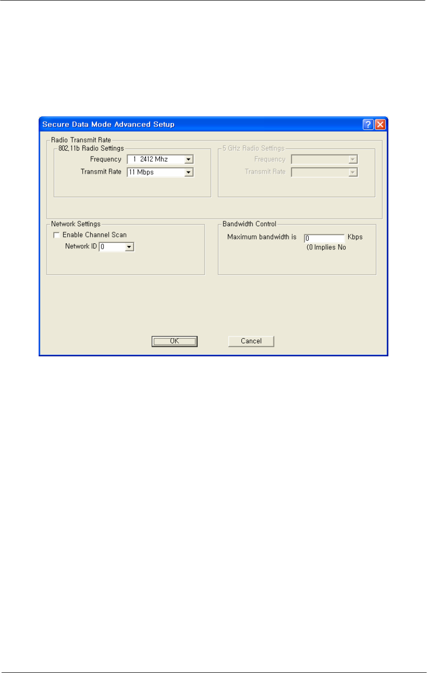
101
WLAN Cable Access Point 6220 NTPM99CA Rel 1.0 Issue 2 Nov 2004
The appearance of the 802.11b Setup screen varies depending on which
options are set on the 802.11b Setup screen. The 802.11b Advanced
Setup screen for a Secure Data Mode Base Station is shown below.
Figure 4-37
Secure Data Mode Advanced Setup window
The 802.11b Secure Data Mode Base Station Advanced Setup screen is
used to set up advanced features for an 802.11b Secure Data Mode base
station.
Network ID-- Enter the Secure Data Mode network ID number (0-15)
used to differentiate between multiple Secure Data Mode stations using
the same System Access Pass Phrase. This is used to allow a Secure Data
Mode satellite to specify the Base Station it wants to connect to if two
base stations can be seen by the same satellite. Generally, this value
should be the same as the Channel Number.
Radio Transmit Rate-- Select the radio bit rate used to transmit.
Your choices are:
Auto-select (IEEE 802.11 only)
Low (1 Mbps)
Standard (2 Mbps)
Medium (5.5 Mbps)
High (11 Mbps)

102
WLAN Cable Access Point 6220 NTPM99CA Rel 1.0 Issue 2 Nov 2004
A lower signal will increase the noise. In essence, the poorer the signal-
to-noise ratio, the lower this rate should be set.
Note: The transmit rate affects only the transmissions made by this
station.
802.11b Frequency Setup-- Clicking the Frequency button on the
802.11b Setup screen displays the 802.11b Frequency Setup screen,
which allows you to set the Frequency Channel for your 802.11b radio
card.
The 802.11b Frequency Setup screen is used to change the channel and
frequency for one of the remote devices on your network. Note that this
screen is only accessible if you have identified remote devices in your
network. If all devices are in your local network, then the Frequency
Setup screen is unavailable.
Channel/Frequency-- Select the channel and frequency for the remote
device from the drop-down list. See Frequency Channels for a more
detailed explanation of the frequency channels.
Note: The channel/frequency values are usually determined by network
administrators. If you set the channel and frequency ensure that there are
at least four numerical channels difference between two overlapping
cells to avoid interference. For example, channels 1, 6 and 11 don’t
overlap, but channels 1 and 3 do.
Hotspot Mode Advanced Setup
Clicking the Advanced Button on the 802.11b Setup screen displays the
802.11b Advanced Setup screen, which allows you to configure more
options related to the setup of your 802.11b network devices.
The appearance of the 802.11b Setup screen varies depending on which
options are set on the 802.11b Setup screen. The 802.11b Advanced
Setup screen for a Hotspot Mode Base Station is shown below.
The 802.11b Hotspot Mode Base Station Advanced Setup screen is used
to set up advanced features for an 802.11b Secure Data Mode base
station.