MTI WCAP6220CSU WiFi Transceiver User Manual Part 2
MTI Co., Ltd. WiFi Transceiver Users Manual Part 2
MTI >
Contents
- 1. Users Manual Part 1
- 2. Users Manual Part 2
Users Manual Part 2
103
WLAN Cable Access Point 6220 NTPM99CA Rel 1.0 Issue 2 Nov 2004
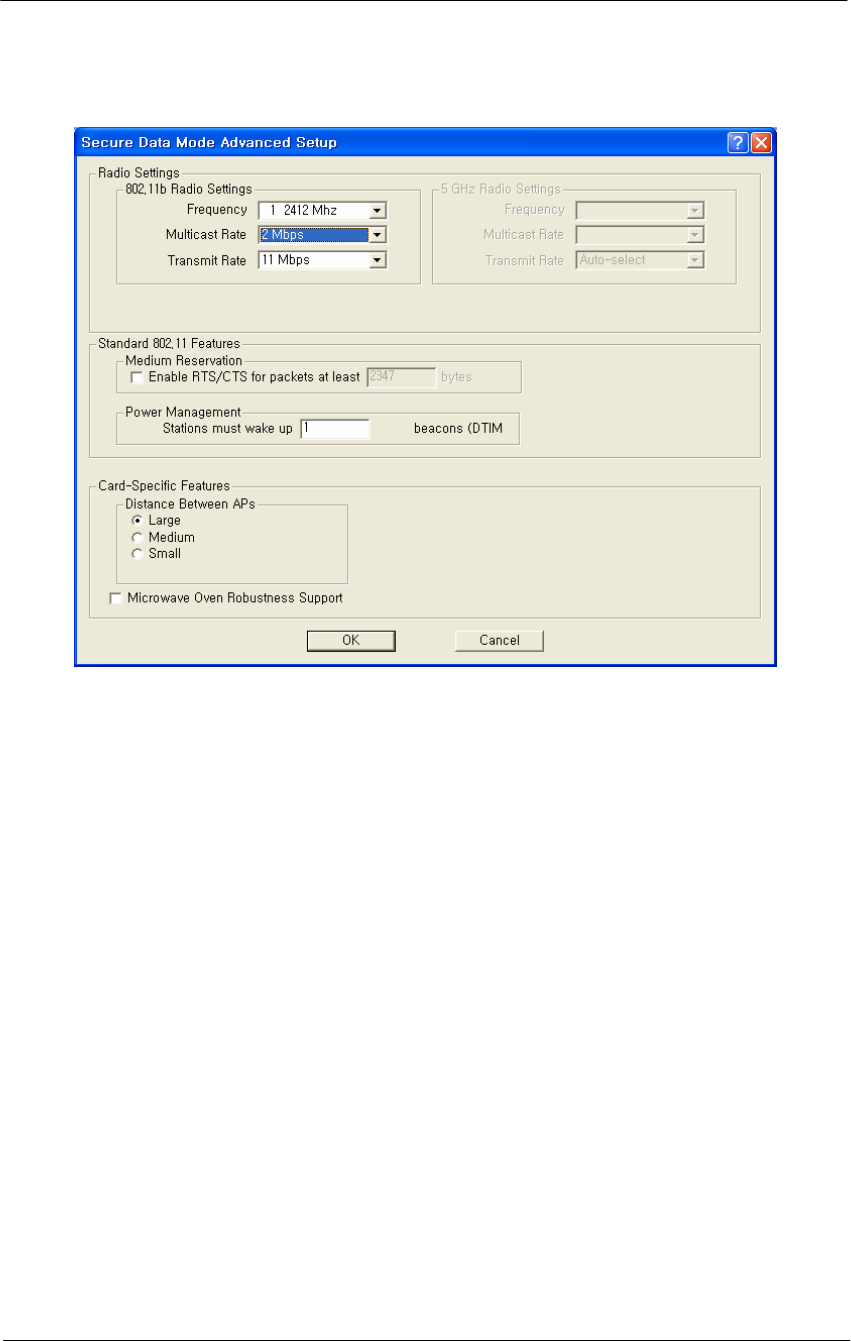
Figure 4-38
Hotspot Mode Advanced Setup window
Channel/Frequency-- Select the channel and frequency for the remote
device from the drop-down list. See Frequency Channels for a more
detailed explanation of the frequency channels.
Radio Transmit Rate-- Select the radio bit rate used to transmit.
Your choices are:
Auto-select (IEEE 802.11 only)
Low (1 Mbps)
Standard (2 Mbps)
Medium (5.5 Mbps)
High (11 Mbps)
Multicast Rate-- Select one of the following values:
1 Mbps
2 Mbps
5.5 Mbps
11 Mbps
Note that for data communication with wireless clients in its vicinity, the
802.11 device is able to determine the appropriate Transmit Rate for each
client individually.

104
WLAN Cable Access Point 6220 NTPM99CA Rel 1.0 Issue 2 Nov 2004
However, for "anonymous data traffic" such as Multicast messages that
must be transmitted to all stations simultaneously, the LAN
Administrator must identify the correct Multicast Rate.
Warning: Selecting the 5.5 Mbits/sec or 11 Mbits/sec values in network
environments that do not satisfy these requirements may result in
Multicast messages getting lost.
Enable RTS/CTS - Select this checkbox to enable the Medium
Reservation mechanism.
When you enable Medium Reservation, the APU will use the Request to
Send/Clear to Send (RTS/CTS) protocol to control wireless data
transmissions, based on the length of the data frame that is to be
transmitted.
RTS/CTS Threshold-- Enter a Medium Reservation Threshold value.
Valid values are any decimal value in the range of 0 to 2347. The default
value of 2347 indicates that Medium Reservation is disabled.
Note: Most vendors recommend using a threshold of around 500.
DTIM Period-- The Delivery Traffic Indication Map (DTIM) parameter
influences the handling of Multicast messages that need to be transmitted
to the wireless medium.
Valid values are any digit in the range of 1 through 65535. The
recommended value is 1. Note that the default value of "0" indicates the
default used by the manufacturer of the radio card, not "0" milliseconds.
Distance between access points—This selection impacts the multicast
rate. ALL stations connected to an AP need to receive broadcasts/
multicasts or some protocols (e.g. IP ARP) will not work, therefore, the
distance between the multiple AP multicasts without negatively
impacting performance. The value set (Small, Medium, Large) should be
the value that guarantees that all stations will receive the broadcasts.
The following table explains the relationship between these two fields:
Multicast Rate Then Set Distance Between APs to ...
1 Mbps Large
2 Mbps Medium
5.5 Mbps Medium
11 Mbps Small
105
WLAN Cable Access Point 6220 NTPM99CA Rel 1.0 Issue 2 Nov 2004
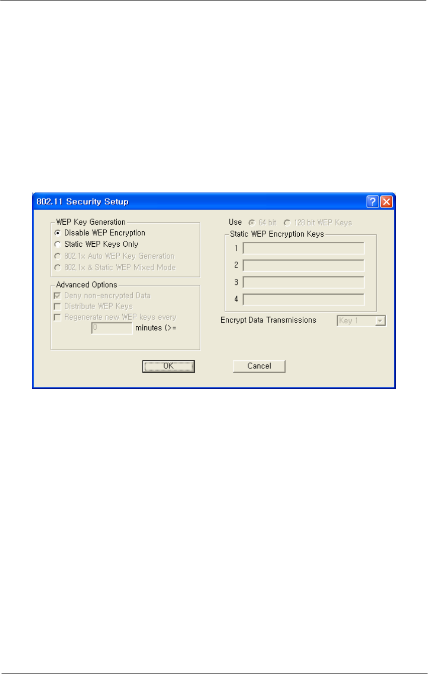
802.11b Security Setup
Clicking the Security button on the 802.11b Setup screen displays the
802,11b Security Setup screen, which allows you to set up security for
your 802.11b devices. Note that the fields shown in the screenshot
below will vary depending on the version of the Configurator you are
using and the options contained in the .bin file. The screen below shows
all available options.
Figure 4-39
802.11 Security Setup window
Disable WEP Encryption-- Select this button if you wish to disable
Wired Equivalent Privacy (WEP) encryption.
If you are not concerned about security (for example, home users using
this device only to browse the Internet), and if you are not concerned
your AP is used by others, then select this checkbox.
Note: For simple security, you can disable WEP encryption and select
the Closed Wireless System checkbox.
Static WEP Keys Only-- Select this button if you wish to enter Wired
Equivalent Privacy (WEP) keys identically on each access point/station
and Secure Data Mode unit in the network. When you select this button,
the four Static EP Encryption key fields are enabled on the right side of
the screen.

106
WLAN Cable Access Point 6220 NTPM99CA Rel 1.0 Issue 2 Nov 2004
802.1x Auto WEP Key Generation-- Select this option if you wish to
automatically create Wired Equivalent Privacy (WEP) keys using the
802.1x protocol. Selecting this option prevents you from creating static
WEP keys.
802.1x & Static WEP Mixed Mode-- Select this option if you wish to
automatically create Wired Equivalent Privacy (WEP) keys using the
802.1x protocol and also allow static keys.
Deny Non-Encrypted Data-- Select this checkbox if you want to deny
all received data that is not encrypted. When this checkbox is selected,
any packet received that is not encrypted using one of the four WEP
Encryption keys listed above will be dropped. When this checkbox is not
selected, unencrypted packets will be accepted and/or forwarded.
Warning: You should always select this checkbox if WEP is enabled in
any form. If disabled, clients without WEP can access your network!
Distribute WEP Keys-- If auto key generation is done in any form
(auto-only or mixed mode), then the keys must be distributed to the
stations. If you have 802.1x enabled on the interface, and STATIC
generation ONLY, then the statically defined keys can still be distributed
to 802.1x stations. However, if you do not have 802.1x, you cannot
distribute WEP keys; and you must use Static keys and enter them
manually.
Regenerate New WEP Keys Every n Minutes-- When generating keys,
change them every n minutes and send them to the access point/station.
Note: This option is only available for 802.1x devices.
Note: This option only applies if you have selected Auto WEP Key
Generation.
Use n-bit WEP Keys-- Select either 64-bit (silver) or 128-bit (gold)
encryption keys. The higher bit count provides somewhat higher security.
Static WEP Encryption Keys-- If you use static encryption keys, you
must enter each key in the Static WEP Encryption Keys fields. Note that
these keys must be entered identically on each access point/station and
Secure Data Mode unit in the network.
Encrypt Data Transmission Using Key n-- Enter the key number that
should be used to encrypt data on this interface. Note that you can
receive using any key, but will generally always transmit using a single
key. Unicast transmissions to an 802.1x station with dynamic keys will
107
WLAN Cable Access Point 6220 NTPM99CA Rel 1.0 Issue 2 Nov 2004
use that’s station’s dynamic key, but all broadcasts, multicasts, and other
unicasts will be encrypted using the key identified in this field.
Closed Wireless System-- Select this checkbox if you wish to require
802.11 stations to have the 802.11 Service Set Identifier/Network Name
entered on their system. Stations without the correct network name will
be denied access. Selecting this option indicates that you do not want the
AP to broadcast the SSID. For example, if you select this checkbox,
then Windows XP will not be able to see the AP.
Note: For simple security, you can disable WEP encryption and select
the Closed Wireless System checkbox. Note, however, the Closed
Wireless System checkbox applies only to Orinoco radios.
Configure the APU for Basic MAC Authentication
Advanced Authentication allows you to restrict access to an 802.11
access point by specifying the MAC Addresses of stations that can use
the wireless bridge
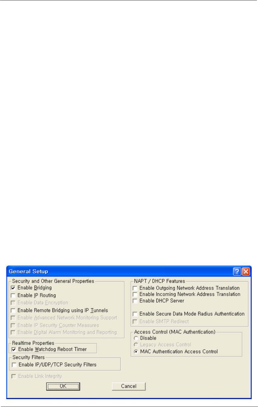
1. Select the Setup Tab, and then click the General Setup button. The
General Setup screen is displayed, as shown below.
2. Select the MAC Authentication Access Control radio button, as
shown in the screenshot, then click OK to close the General Setup
screen.
3. Click the Advanced Authentication button. The Advanced
Authentication Setup screen is displayed, as shown in Figure 4-40.
Figure 4-40
General Setup Window
108
WLAN Cable Access Point 6220 NTPM99CA Rel 1.0 Issue 2 Nov 2004
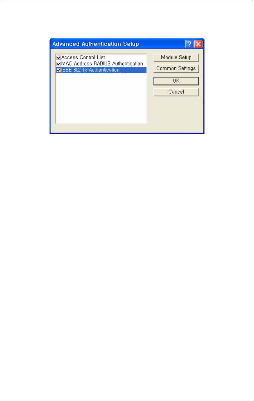
Figure 4-41
Advanced Authentication Setup Window
When a station tries to connect to the hardware device (via Ethernet,
802.11, etc.), the AP can decide whether or not to forward packets to or
from that station based on authorization criteria. There are three
authentication modules that comprise MAC authentication, but the
network administrator determines which of those three modules are used.
• Access Control List (ACL)
• MAC RADIUS Authentication (with optional WARP support)
• 802.1x
These modules are enabled on a per-interface basis. This provides
greater control for the network administrator. In essence, the
administrator decides whether there will be more or less (or no)
authentication on an interface-by-interface basis.
For example, an administrator can permit MAC addresses entered as part
of the ACL only on 802.11b, but can permit MAC addresses entered
through RADIUS Setup for both the Ethernet and 802.11b interfaces.
The modules are checked in the order in which they appear on the
Advanced Authentication Setup screen, and the options that have been
selected (checked) determine how authentication is carried out.
Assuming that all options are selected, the first method used is the
Access Control List, followed by MAC Address Radius, followed by
802.1x authentication. If no options are selected, then no authentication
takes place. Zero to three of the modules can be enabled, but at least one
module must be enabled for advanced authentication to take place.
The process by which authentication takes place is as follows:
109
WLAN Cable Access Point 6220 NTPM99CA Rel 1.0 Issue 2 Nov 2004
The first module in the list (for example, ACL) checks the source
address of the incoming packet to see if it is permitted to send
packets on the selected interfaces.
The module will designate the address as one of the following:
• Permit -- the MAC address is permitted on this interface, and
packets are forwarded
• Deny - the MAC address is denied on this interface, and the
packets are not sent
• Unknown - the MAC address is not known on this interface, and
is passed to the next authentication module
If the designation is unknown, then it is passed to the next module in
the list (for example, from the ACL to MAC RADIUS
Authentication), and the process starts again.
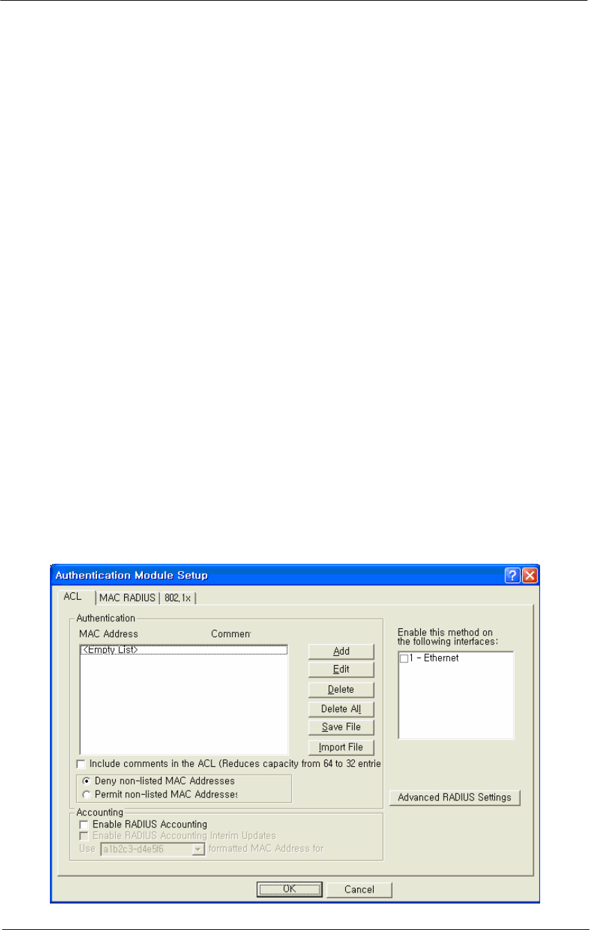
Ensure that the MAC Address RADIUS Authentication checkbox is
enabled, and then click the Setup button. The Authentication Module
Setup screen is displayed as shown below.
Note: The number of tabs displayed on this screen will vary depending
on which Advanced Authentication options you have selected on the
Advanced Authentication Setup screen. In the screenshot below, all
Advanced Authentication options have been enabled.
Figure 4-42
Authentication Module Setup Window
110
WLAN Cable Access Point 6220 NTPM99CA Rel 1.0 Issue 2 Nov 2004
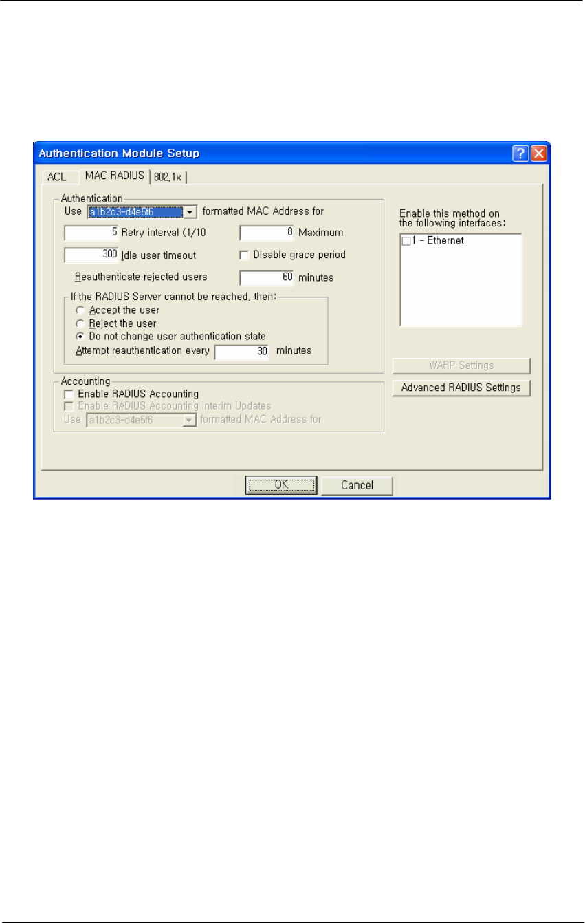
4. Click the MAC RADIUS tab. The MAC RADIUS Setup screen is
displayed, as shown below.
Figure 4-43
Authentication Module Setup Windows
The MAC RADIUS Setup screen is used to define advanced
authentication and accounting options for clients that are authenticated
via RADIUS using the client's MAC Address as the RADIUS username.
RADIUS authentication and accounting server IP addresses and port
numbers are set up using the MAC RADIUS Setup screen. Note that this
particular MAC RADIUS module applies only to Ethernet and 802.11
access point interfaces.
This screen is used in conjunction with the RADIUS Server Setup screen
to define various authentication options. If you wish to use accounting,
you must first set up accounting parameters on the RADIUS Server
Setup screen.
5. Enter values in the RADIUS Server Setup screen to configure your
RADIUS server. Each field on the screen is explained in more detail
below.
Use formatted MAC Address for username-- Select “A1-2B-3C-45-
CD-EF” if you wish to use all uppercase formatting for MAC address
accounting. This format corresponds to the new RFC RADIUS
standards.

111
WLAN Cable Access Point 6220 NTPM99CA Rel 1.0 Issue 2 Nov 2004
Select a1b2c3-d4e5f6 if you wish to use the older formatting of MAC
addresses. Select the EAP packet username if you wish to use the EAP
packet username (802.1x Authentication only).
Enable this method on the following interfaces.
Select the interfaces used for MAC RADIUS authentication.
Note: You can select either the Ethernet or 802.11b interface if you wish
to use WARP.
Retry Interval-- The retry interval for authentication, in tenths of a
second. The default value is 5, or a retry interval of .5 seconds. You can
set the retry interval to any value between 3 (.3 seconds) and 30 (3
seconds).
Maximum Retries-- The number of times the access point will retry to
connect with the server. The default value is 8(eight), and the range for
retries is between 1(one) and 10(ten).
Idle User Timeout (sec)
Enter a value in this field if you wish to disconnect users after a period of
inactivity. The value entered will be the number of seconds that must
pass without activity before users are disconnected.
The default value is 300 seconds (or five minutes). The range of
accepted values is between 0 and 3825.
Disable Grace Period -- The grace period allows a client to roam
between access points without losing open TCP connections. Select this
checkbox if you wish to disable the grace period. If selected, the user
does not receive a grace period; if unselected, the user receives a grace
period.
Note: The Grace Period must be enabled (unchecked) if you wish to use
WARP.
Re-authenticate Rejected Users Every n Minutes -- Select the interval
at which users who have not been authenticated will be allowed to re-
authenticate. The default interval is 60 minutes.
Accept the User-- Select this radio button if you wish to allow network
access to the user if the RADIUS server is down.
Reject the User -- Select this radio button if you wish to deny network
access to the user if the RADIUS server is down.

112
WLAN Cable Access Point 6220 NTPM99CA Rel 1.0 Issue 2 Nov 2004
Do not change user authentication state-- Select this checkbox if you
wish to keep the user authentication state the same as that before the
RADIUS server went down. When this checkbox is selected, if the user
was authenticated before the server went down, then the user will remain
authenticated. If the user was not authenticated before the RADIUS
server went down, then the user will remain unauthenticated.
Note: This field is used in conjunction with the "After n Failed
Authentication Attempts and "Make users wait n seconds" fields.
Attempt Re-authentication Every n Minutes -- If the RADIUS server
cannot be reached, the access point will attempt to authenticate all clients
via the RADIUS server according to the interval specified here. The re-
authentication interval must be specified in increments of 15 minutes.
Valid values are 15, 30, 45, etc.
Enable RADIUS Accounting --Select this button if you wish to enable
RADIUS accounting. Accounting keeps track of the number of bytes
and packets sent by a client. It also keeps track of the amount of time a
client has been authenticated. You will want to select this button if you
wish to monitor the amount of traffic a client passes, or the amount of
time a user is logged on. Typically, you will do this if you wish to bill
the client based on time or traffic.
Note: Accounting must be used with authentication. You cannot use
accounting without authentication.
Enable RADIUS Accounting Interim Updates -- Select this checkbox
if you wish to allow RADIUS accounting updates. If this feature is
enabled, the number of bytes and packets sent by a client will be updated
according to the update interval defined on the Advanced RADIUS Setup
screen.
WARP Settings Button -- Clicking this button displays the WARP
Settings screen, which allows you to define various IP addresses and
ports that will be used for Wireless Authentication and Registration
Protocol (WARP).
Advanced RADIUS Settings Button -- Clicking this button displays the
Advanced RADIUS Settings screen, which enables you to define more
advanced RADIUS parameters.
113
WLAN Cable Access Point 6220 NTPM99CA Rel 1.0 Issue 2 Nov 2004
Configure the APU for Advanced RADIUS MAC Authentication
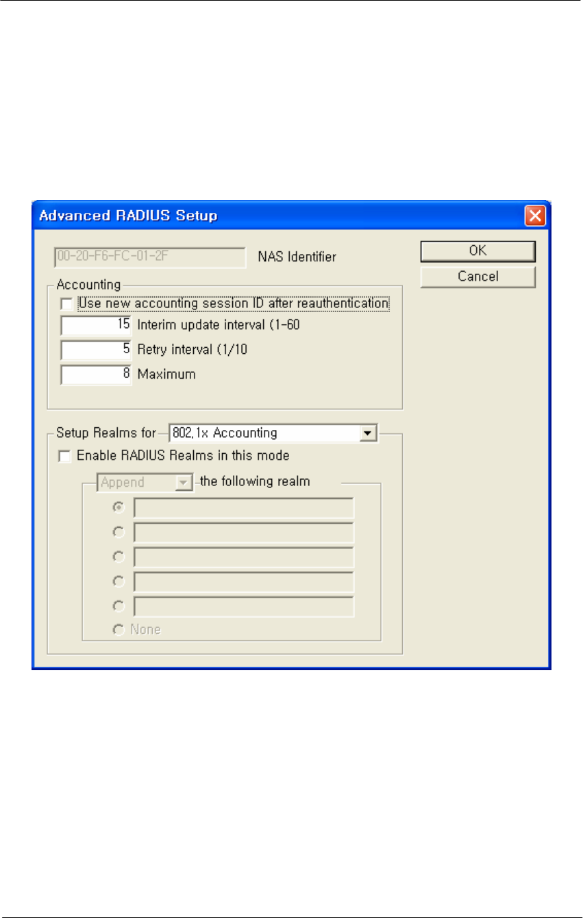
1. From the MAC RADIUS Setup screen, click the Advanced RADIUS
Settings button. The Advanced RADIUS Setup screen is displayed,
as shown below.
Figure 4-44
Advanced RADIUS Setup Window
The Advanced RADIUS Setup screen is used to configure optional
RADIUS-related parameters.
2. Enter values in the Advanced RADIUS Setup screen, as indicated by
the field descriptions below.
NAS Identifier - This field displays your Network Access Server (NAS)
name. The access point's SNMP System Name is used as the NAS
Identifier, and is shown here for your convenience.
Note: The NAS ID takes the place of the IP address that would normally
be used to identify the AP.

114
WLAN Cable Access Point 6220 NTPM99CA Rel 1.0 Issue 2 Nov 2004
Use New Accounting Session ID After Authentication -- Select this
checkbox if you wish to use another ID for accounting after
authentication has taken place.
Interim Update Interval -- Set the interval (in minutes) between interim
updates.The interim update is used to send information in between
normal "start/stop" packets. Interim updates are useful because they
provide a log of network traffic at a regular interval.
The default value for the interim update interval is 15 minutes. The
interim update must be between 1 - 60 minutes.
Retry Interval (1/10 sec) -- The retry interval for accounting, in tenths
of a second. The default value is 5 (or a retry interval of .5 seconds).
You can set the retry interval to any value between 3 and 30.
Maximum Retries -- The number of times the access point will retry to
connect with the server. The default value is 8, and the range for retries
is between 1 and 10.
Set Up Realms for -- When an access client sends user credentials, a
user name is often included. Within the user name are two elements:
• Identification of the user account name
• Identification of the user account location
For example, for the user name user1@microsoft.com, user1 is the user
account name and microsoft.com is the location of the user account. The
identification of the location of the user account is known as a realm.
With RADIUS, a realm is used to separate one name space from another.
This allows you to create a login such as user@dom1.com and another
login such as user@dom2.com. RADIUS realms also allow Internet
Service Providers (ISPs) to segment customer logins, so authentications
go to the appropriate RADIUS server(s).
A domain is registered with the InterNIC, and used for mapping servers
and services to IP addresses, such as Web, e-mail, etc. Typically, a
RADIUS realm corresponds to a domain name (e.g., microsoft.com;
yahoo.com). However, there is no requirement to do so, and in fact ISPs
often assign realms with no top-level domain (for example, user@dom1 -
- without a .com extension).

115
WLAN Cable Access Point 6220 NTPM99CA Rel 1.0 Issue 2 Nov 2004
From the dropdown list, select the accounting or authorization feature for
which to provide special handling of <RADIUS realms>. Options
currently include:
• 802.1x Accounting
• 802.1x Authorization
• Access Control List (ACL) RADIUS Accounting
• MAC RADIUS Accounting
• MAC RADIUS Authorization
For each of the above Authentication/Accounting types, special handling
of RADIUS Realms can be enabled or disabled using the "Enabled
RADIUS Realms in this mode" checkbox. Depending on the selected
Authentication/Accounting type, different options are available for how
to handle RADIUS realms.
Following Realm Name -- Select the type of behavior that will be used
for the realm. The behavior determines how the access point handles the
realm. Select one of the following realm types:
Append -- Takes the user supplied user name, and appends the realm
name onto it (for example, if the user name is smith and the realm name
is microsoft.com, then the append action produces
smith@microsoft.com)
Supply -- Supplies the selected realm name if the user does not already
have one selected. If the user provided a realm name, then use the
provided realm name, and do not use the one provided.
• Example #1: User provided smith, Behavior is set to Supply, and
user did not provide a realm name. The supply action produces
jsmith@microsoft.com.
• Example #2: User provided smith, Behavior is set to Supply, and
user provided the realm name yahoo.com. The supply action
produces jsmith@yahoo.com).
Require -- Requires the user to use the selected realm name (or none, if
none is selected). If there is a realm name in the realm name field, the
user must have the realm name indicated by the radio button. If the user
does not, then he or she is not authenticated. If none is selected, then the
user is required not to have a realm name.
• Example #1: User provided smith, Behavior is set to require,
user has the realm name microsoft.com, but yahoo.com is entered
in the realm name field. The user is not authenticated.
• Example #2: User provided smith, Behavior is set to require,
user has the realm name microsoft.com and microsoft.com is
entered in the realm name field. The user is authenticated.)

116
WLAN Cable Access Point 6220 NTPM99CA Rel 1.0 Issue 2 Nov 2004
Force -- Replaces any realm name supplied by the user with the selected
realm name, or strips off the realm name supplied by the user in the case
of none.
• Example: User provided smith, Behavior is set to Force, user
provides the realm name microsoft.com, but yahoo.com is
entered in the realm name field. The user is authenticated as
jsmith@yahoo.com)
Note: The available behaviors vary depending on the type of accounting
or authorization realm selected. The following table shows the types of
behaviors available for each type of accounting or authorization realm.
Table 4-3
Type of Accounting/Authorization Realm Behavior(s) Available
802.1x Accounting • Append
802.1x Authentication • Append
• Supply
• Require
• Force
ACL Radius Accounting • Append
MAC RADIUS Accounting • Append
MAC RADIUS Authentication • Append
117
WLAN Cable Access Point 6220 NTPM99CA Rel 1.0 Issue 2 Nov 2004
Set Up HotSpot Functionality
You are now ready to set up HotSpot functionality.
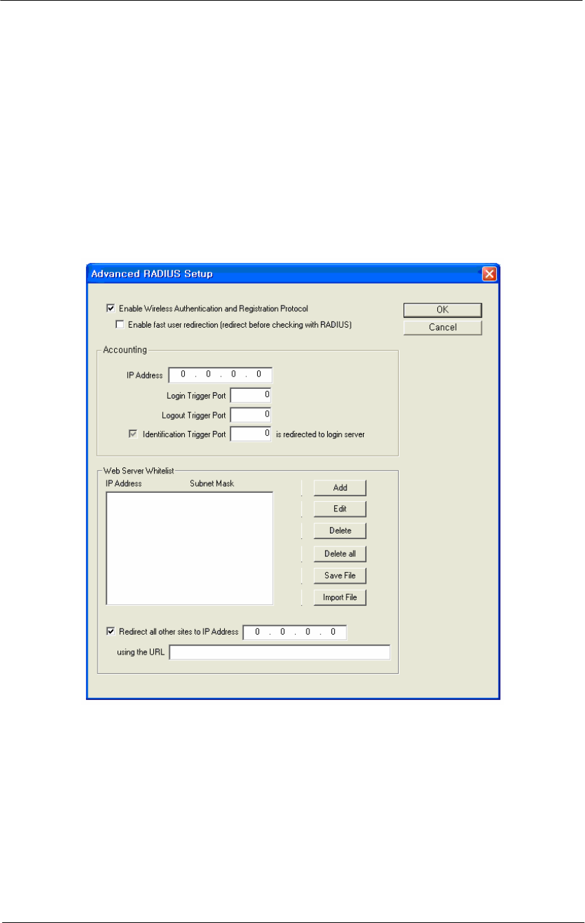
1. From the MAC RADIUS Setup screen, click the WARP Settings
button. The WARP Settings screen is displayed, as shown below.
Enter the HotSpot configuration information on this screen, as
explained below.
Figure 4-45
WARP Settings Window
The WARP Settings screen is used to set up parameters for Wireless
Authentication and Registration Protocol (WARP).
The WARP feature enables the creation of Hotspots for wireless access.
This allows wireless users to access the Internet from their laptops or
PDAs, typically on a pay-per-use basis. When WARP is enabled, all
traffic is redirected to a login web server, and users will be unable to
access other web pages until they have successfully logged in.
Each of the fields and buttons on the WARP Setup screen are explained
below.

118
WLAN Cable Access Point 6220 NTPM99CA Rel 1.0 Issue 2 Nov 2004
Enable Wireless Authentication and Registration Protocol -- Select
this checkbox to enable the Wireless Authentication and Registration
Protocol (WARP) feature. Note that once this checkbox is selected, the
other fields on the screen become available.
Enable fast user redirection (redirect before checking with RADIUS)
-- Select this checkbox if you wish to provide immediate access to the
Internet without going through the RADIUS authentication process.
When enabled, this option redirects all users without consulting the
RADIUS server. Users who have an account with time left do not have to
repeat the login process. This is particularly useful for roaming,
recovery from idle timeouts, and fast Internet access. It is also useful if
you wish to show a "splash screen" to all users.
If unselected, users will be redirected to the login server or their home
page. The AP is put in a "grace period" and a request is sent to the
RADIUS server. Established TCP connections may continue while the
request is pending (supports roaming without re-login at each AP). When
the response is received, the AP is either redirected to login, or allowed
full access to the Internet. Users with time remaining are given a link that
bypasses the registration process, and proceed directly to the redirect
through the login trigger port. Note that users with no account go
through the normal login procedure.
Authentication Web Server IP Address -- Enter the IP address of the
web server that should be used for WARP. When WARP is enabled, all
traffic will be redirected to this login web server, and users will be
unable to access other web pages until they have successfully logged in
on a pay-per-use basis.
Authentication Web Server Login Trigger Port -- Enter the number of
the port used in conjunction with the IP address of the login web server
for WARP. The login server directs successful logins to the trigger port,
which makes the access point attempt a second RADIUS authentication.
This authentication should be successful because the login updated the
RADIUS server client list. The second RADIUS request is done by the
access point when it sees traffic to the trigger port.
Note: The login trigger port cannot be the same port as the port used for
the login page or the logout trigger port.
Authentication Web Server Logout Trigger Port -- Enter the number
of the port used in conjunction with the IP address of the logout web
server for WARP. The logout server directs successful logouts to the

119
WLAN Cable Access Point 6220 NTPM99CA Rel 1.0 Issue 2 Nov 2004
trigger port, which attempts a second RADIUS authentication. This
authentication should fail because the logout updated the RADIUS server
client list. The second RADIUS request is done by the access point
when it sees traffic to the logout trigger port.
Note: The logout trigger port cannot be the same port as the port used
for the login page or the login trigger port.
Identification Trigger Port n is redirected to Login Server –
Enter the port number that the client will be redirected to when the web
server needs to obtain the client's identification information. When the
Access Point sees the client attempting to connect to the Identification
Trigger Port, the client will be redirected to the login server at port 80
and the URL will be filled in with the client's MAC Address by the
Access Point.
Note: The Identification URL is independent of the White list URL
displayed at the bottom of the WARP Settings screen.
Web Server White list -- The Web Server White list allows you to add
or edit IP address/subnet mask pairs that correspond to websites that can
be accessed before the user is authenticated. For example, if HotSpot
access is being used in a coffee shop, the coffee shop might provide
access to its own web site without requiring authentication.
These IP address/subnet mask appear in the Web Server White list
window once they have been created.
Clicking the Add button displays the IP Address White list Entry screen,
and allows you to add new IP address/subnet mask pairs to your white
list.
Selecting an IP address/subnet mask pair in your white list and clicking
the Edit button also displays the IP Address White list Entry screen, and
allows you to edit one or both of the IP address/subnet mask entries for a
particular website.
Selecting an IP address/subnet mask pair in your white list and clicking
the Delete button deletes that entry from your white list. You are
prompted before the delete occurs.
Clicking the Delete All button deletes every entry in your white list.
You are prompted before the delete occurs.

120
WLAN Cable Access Point 6220 NTPM99CA Rel 1.0 Issue 2 Nov 2004
Clicking the Save File button allows you to save the IP address/subnet
mask entries in your white list to an external file, which can then be
imported at a later time.
Clicking the Import File button displays the standard Windows Open
File dialog, and allows you to navigate to the directory where a
previously saved white list can be selected and imported into the
configurator.
Redirect all other sites to IP Address -- Enter the IP address that will
be used to redirect all other sites. The IP address should be associated
with the URL entered in the field below.
Using the URL -- Enter the URL (using format
http://www.sitename.extension) to which all other sites will be
redirected. The URL must be associated with an IP address entered in
the web server white list or the WARP login server, or the AP will be
redirected forever.
If no URL is given, APs will be redirected to "http://<server-IP>/login".
This URL is useful to hide the IP, to change the location of the login
page, or to redirect to a non-login home page. Note that you must enable
the Identification Trigger Port to complete the login process.
Configure the RADIUS Server for Hotspot Service
Once the AP has been configured for basic operation, you are ready to
configure the device for HotSpot Mode and Firewall functionality.
This is a four-step process:
• Configure the RADIUS Server for Authentication (and,
optionally, Accounting)
• Configure the APU for Basic RADIUS MAC Authentication.
• Configure the APU for Advanced RADIUS MAC
Authentication.
• Set up HotSpot Functionality
Each step is explained in more detail below. Note that this section
assumes that you have launched the AP Configurator and that you have
completed all steps in Configure the Access Point for Basic Operation
section.
1. From the Setup tab on the Configurator, click the RADIUS Server
button. The RADIUS Authentication and Accounting Server Setup
screen is displayed, as shown below.
121
WLAN Cable Access Point 6220 NTPM99CA Rel 1.0 Issue 2 Nov 2004
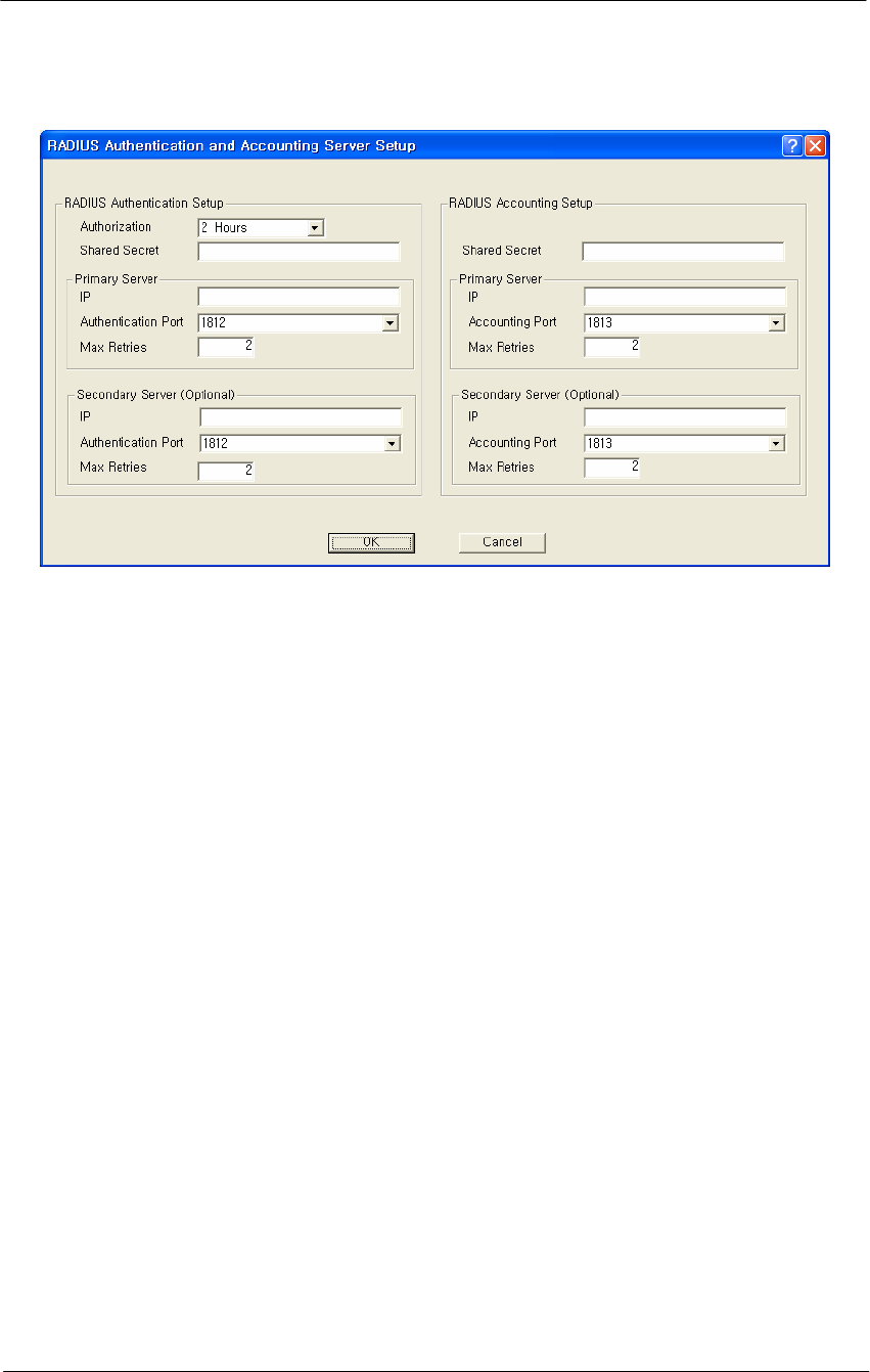
Figure 4-46
RADIUS Setup Window
The RADIUS Server Setup screen is used to configure authentication and
accounting parameters for terminal servers that speak the RADIUS
protocol.
RADIUS is the de-facto standard protocol for authenticating users and
for recording accounting information. Accounting keeps track of the
number of bytes and packets sent by a client. It also keeps track of the
amount of time a client has been authenticated. It is commonly used by
Terminal Servers or Network Access Servers (NASs) whenever a user
logs on and off a dialup Internet service.
Note: This screen is only available if the MAC Authentication Access
Control button on the General Setup screen has been selected.
There are two main sections in the RADIUS server setup dialog:
RADIUS Authentication Setup and RADIUS Accounting Setup. In most
cases you will want to set up both, although you do not have to set up
Accounting. The two are almost identical except for the Authorization
Lifetime, which appears only with Authentication.
To set up RADIUS authentication and accounting:
1. Enter values in the RADIUS Authentication and Accounting Server
Setup screen to configure your RADIUS server. Each field on the
screen is explained in more detail below.

122
WLAN Cable Access Point 6220 NTPM99CA Rel 1.0 Issue 2 Nov 2004
Authorization Lifetime -- Authorization lifetime is the length of time
the authorization is valid. Users will need to be-authenticated/re-
authorized after this time expires. You should set this value to the
maximum time you wish a user to be able to use your service without the
need to be re-authenticated.
Shared Secret -- The client file for your RADIUS server contains the IP
address and password for the base station you are setting up. You must
add the IP address and password (shared secret) from this file in the
RADIUS Server Setup screen.
Note: There are separate shared secrets (passwords) for authentication
setup and accounting setup. The shared secret is an ASCII string that
should be between 2 - 32 characters and should not start with a space.
Primary Server IP Address -- In the RADIUS dialog, enter the IP
address for the RADIUS server (the host).
Primary Server Authentication Port -- In the RADIUS dialog, enter
the authentication port (default = 1812) for the RADIUS server (the
host).
Secondary Server IP Address -- If you are using a second RADIUS
server for network robustness, enter the IP address of that RADIUS
server.
Primary Server Accounting Port -- In the RADIUS dialog, enter the
accounting port (default = 1812) for the RADIUS server (the host).
Secondary Server Authentication Port -- If you are using a second
RADIUS server for network robustness, enter the authentication port
(default = 1812) for that RADIUS server (the host).
Secondary Server Accounting Port -- If you are using a second
RADIUS server for network robustness, enter the accounting port
(default = 1812) for that RADIUS server (the host).
123
WLAN Cable Access Point 6220 NTPM99CA Rel 1.0 Issue 2 Nov 2004
Procedure 3-6
Advanced and Optional Configuration
Once you have set up the basic network configuration, you may choose
to set up one or more optional or advanced configuration components.
This chapter describes how to configure the following optional and
advanced components:
Set Up the Bridge
The Bridge Setup screen is used to set up the bridge. In addition, you
may use the following screens to set up optional bridge components:
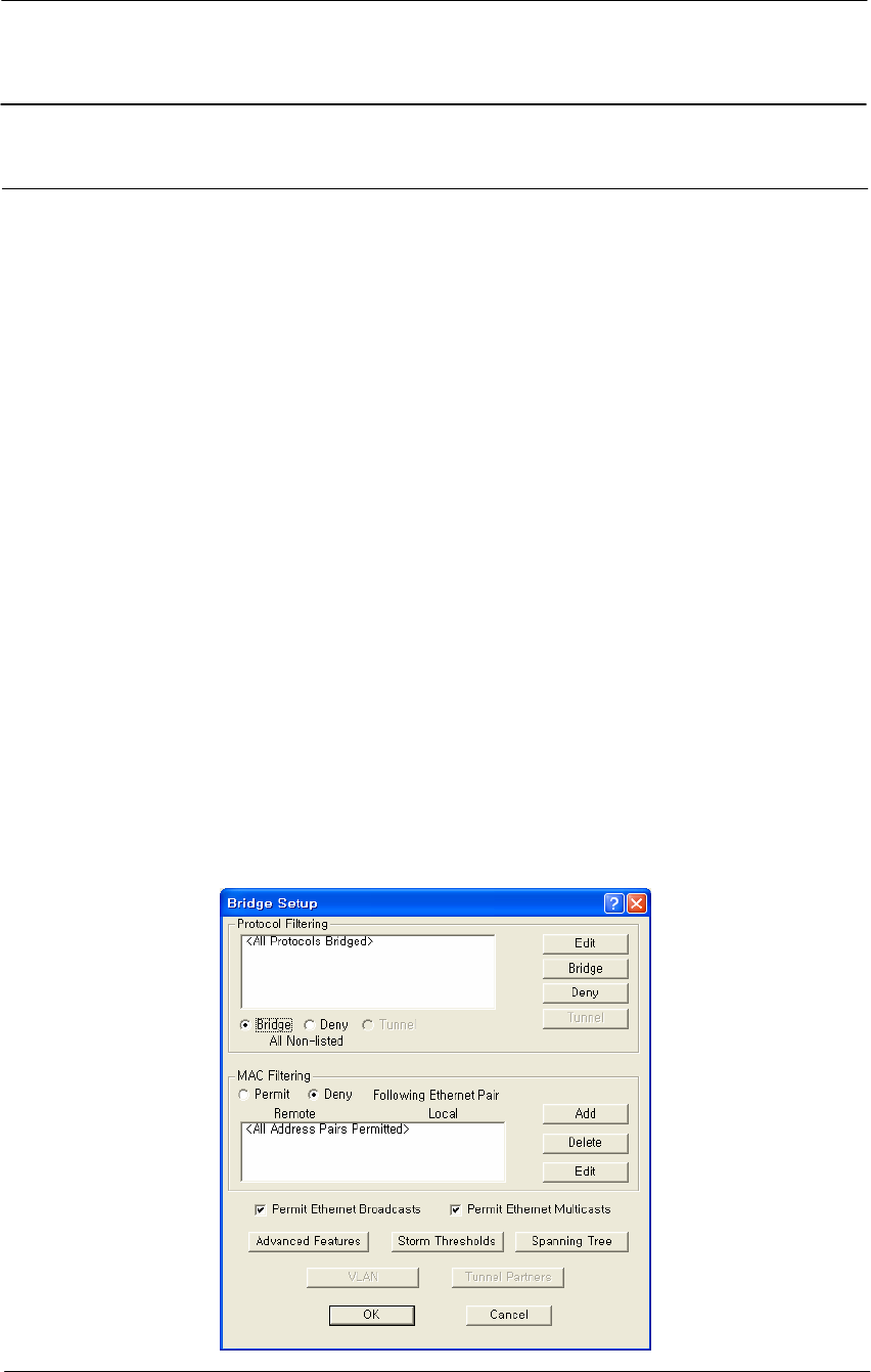
The Bridge Setup screen is used to set up the parameters used for
bridging. In most cases you will not need to modify the factory
configured Bridge Setup. If you are working with an extensive network
environment, however, and if you are an experienced network
administrator, you may want to modify some of the parameters to fit
specific network requirements.
The top half of the screen allows you to define different handling options
based on different protocols. The bottom half of the screen allows you to
define different handling options based on individual MAC addresses.
Note: This screen is only available when the Enable Bridging checkbox
has been selected on the General Setup screen.
Figure 4-47
Bridge Setup window
124
WLAN Cable Access Point 6220 NTPM99CA Rel 1.0 Issue 2 Nov 2004
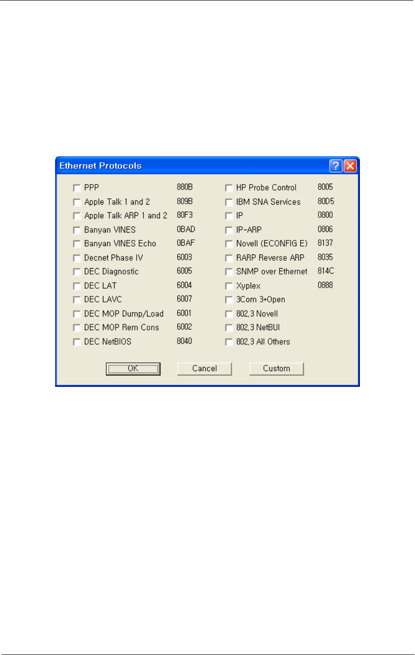
Protocol Filtering
The Protocol Filtering section of the Bridge Setup screen allows you
to select a handling method (Bridge, Deny, or Tunnel) for the most
common protocols.
Figure 4-48
Protocol Filtering Setup window
1. Select the protocols from the list that you wish to handle separately,
or click the Custom button to add an unlisted protocol. Click the OK
button when finished to re-display the Bridge Setup screen. Note
that the protocols you have selected are listed in the Protocol
Filtering window, and that all protocols are denied by default.
2. If you wish to Bridge or Tunnel any of the protocols in the list, select
the protocol, then click either the Bridge or Tunnel buttons
3. At the bottom of the Protocol Filtering list, click the Bridge, Deny, or
Tunnel button to define how all other non-listed protocols should be
handled.
Note: You can add new protocols to the list at any time by clicking the
Edit button and checking additional protocol check boxes.

125
WLAN Cable Access Point 6220 NTPM99CA Rel 1.0 Issue 2 Nov 2004
Tunnel Button--The Tunnel button is used in conjunction with the
protocols listed in the Protocol Filtering list. Select a protocol from the
list and click the Tunnel button to indicate that the selected protocol
should be tunneled.
Deny Button-- the Deny button is used in conjunction with the protocols
listed in the Protocol Filtering list. Select a protocol from the list and
click the Deny button to indicate that the selected protocol should be
denied.
Bridge Button-- the Bridge button is used in conjunction with the
protocols listed in the Protocol Filtering list. Select a protocol from the
list and click the Bridge button to indicate that the selected protocol
should be bridged.
Bridge MAC Address Filtering Overview
You can specify static MAC Address filters in Bridge Setup to optimize
the performance and increase security on your wireless (and wired)
network. You can permit or deny access to individual stations by
specifying their particular MAC Addresses, or to multiple stations by
using an X as a wildcard character. You can also permit or deny
Ethernet multicast address all traffic that does not match one of the pairs
explicitly listed in the Ethernet pair list will be permitted or denied based
on your selection.
Table 4-4
Traffic Filtering
Selection Traffic Matching Listed Pairs Traffic Not Matching Listed
Pairs
Permit Following Ethernet Pair Permit Deny
Deny Following Ethernet Pair Deny Permit
Stations to be filtered are identified by their MAC Address and whether
they are on a remote or local interface. The Interface parameter indicates
whether the station with the specified MAC Address is located on the
wired or wireless interface of the base station. Use the Add, Delete, and
Edit buttons to modify the entries of the list.
Permit Ethernet Broadcasts-- If you wish to deny broadcast traffic in
your bridged network, deselect this option. Normally, however, you will
select this option to permit Ethernet broadcasts.
Note: This option applies to all Ethernet interfaces, and not simply to
Ethernet traffic.
126
WLAN Cable Access Point 6220 NTPM99CA Rel 1.0 Issue 2 Nov 2004
Permit Ethernet Multicasts-- If you wish to deny multicast traffic in your
bridged network, deselect this option. Normally, however, you will select
this option to permit Ethernet multicasts.
Note: This option applies to all Ethernet interfaces, and not simply to
Ethernet traffic.
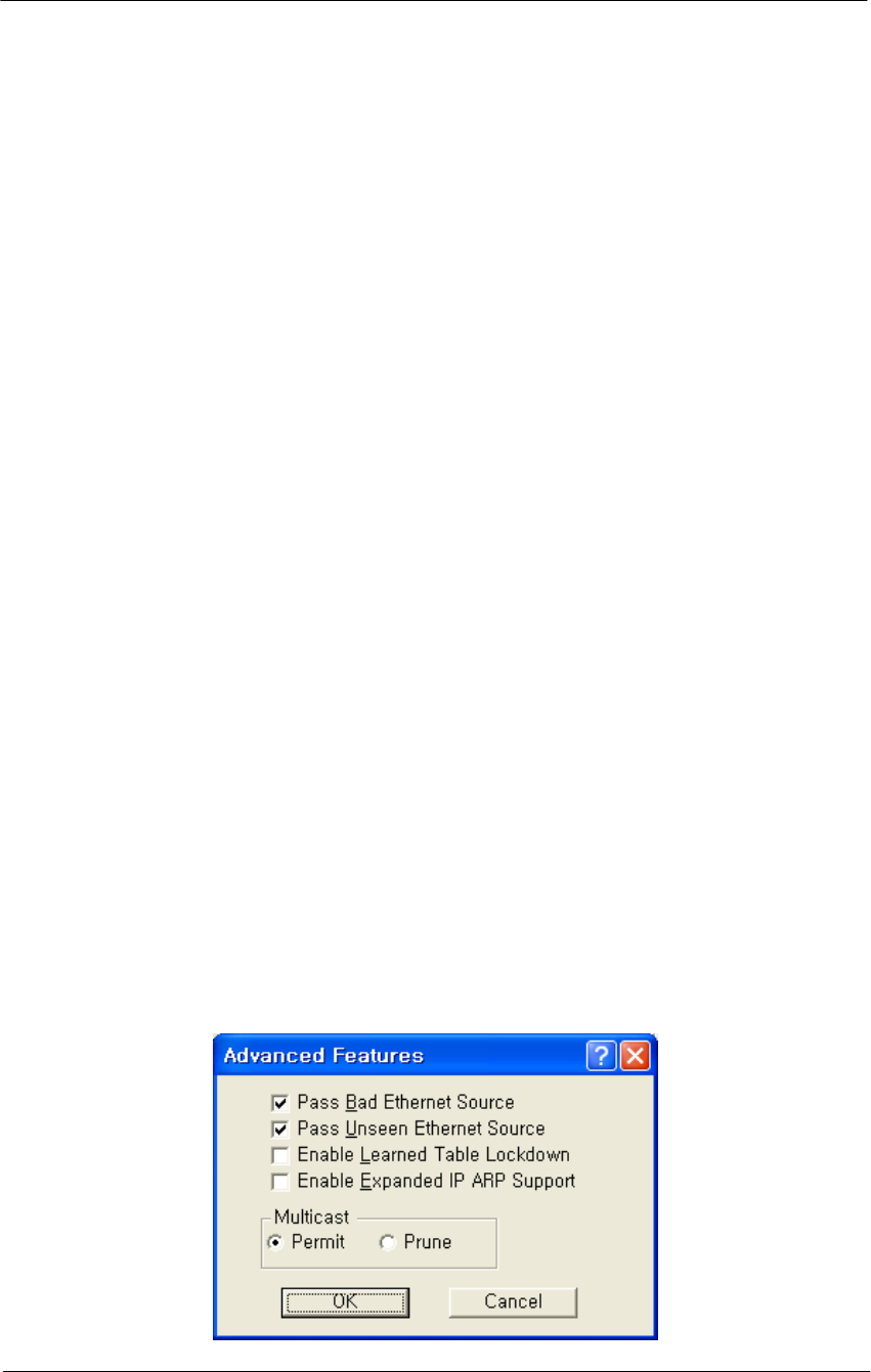
Advanced Bridging Features
The Advanced Bridge features can be accessed by clicking the Advanced
Features button on the Bridge Setup screen.
MAC Layer (Ethernet) Filters allow you to filter Ethernet traffic due to
bad or unknown
DHCP Filtering allows you to limit DHCP responses to a particular
DHCP server.
IP/ARP Filtering allows you to prevent unnecessary IP/ARP packets
from being sent over the wireless link.
Incoming Broadcast Filters allow you to prevent broadcast and multicast
packets arriving from the remote interface(s) from being transmitted on
the local interface(s).
Outgoing Broadcast Filters allow you to prevent broadcast and multicast
packets sent from the local interface(s) from being transmitted out the
remote interface(s).
Miscellaneous Statistics Gathering allows you to enable some
miscellaneous advanced bridging features.
Figure 4-49
Advanced Bridging Setup window

127
WLAN Cable Access Point 6220 NTPM99CA Rel 1.0 Issue 2 Nov 2004
Permit Multicast Button-- Select this checkbox if you wish to permit
multicast.
Prune Multicast Button-- Select this checkbox if you wish to prune
multicast.
Enable Learned Table Lockdown--A standard Bridge/Router watches the
source addresses of each packet it receives on any of its interfaces.
As new addresses are seen, entries are added in the “learned table” that
contain the particular source address and the interface number that
address was received on. If that source address is later seen on a
different interface, the Bridge will immediately change the interface
number in the learned entry table. This condition could happen in a
correctly functioning network if someone moved the computer to a
different part of the network.
This could also happen if someone was trying to capture network packets
by spoofing the Bridge. Enabling learned table lockdown will prevent
the interface number from being changed once the source address has
been seen.
A standard Bridge will also time-out the learned table records every ten
(10) minutes. If learned table lockdown is enabled, these records will not
be timed-out. Once a record is learned, it will not be changed or deleted
until either the Secure Data Mode station reboots or the learned table
becomes completely filled and needs to be reset.
Note: A typical Secure Data Mode learned table can contain over
12,000 records.
Enable Expanded IP/ARP Support
Enabling this feature will cause the Secure Data Mode station to watch
the IP/ARP packets that occur on the network. Normally, no action is
taken in response to an IP/ARP packet that is not destined for a host that
is being Proxy ARPed by the Secure Data Mode station. When this
function is selected, the Secure Data Mode station will add the IP address
to its IP/ARP table when it sees an ARP packet from another source.
This feature is helpful on an ARP network because it will build a
database of MAC layer address to IP address pairs.
Note: The IP/ARP table is never timed out in this mode.
128
WLAN Cable Access Point 6220 NTPM99CA Rel 1.0 Issue 2 Nov 2004
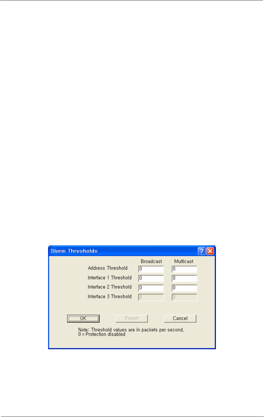
Storm Threshold Setup
The Storm Thresholds screen is used to set threshold values for broadcast
and multicast messages.
In most situations, you will not need to set the Storm Thresholds.
However, if intensive multicast or broadcast messaging is typical of the
network protocols used in your network environment, you may wish to
control the maximum number of broadcast and multicast messages. If the
maximum value of broadcast or multicasts per second is exceeded, the
Secure Data Mode Station will ignore all subsequent messages issued by
the particular network device, or ignore all messages of that type coming
on that particular interface.
You can use the Storm Threshold screen to:
Specify a maximum value as received from a single network device
(identified by its MAC address).
Specify an absolute maximum of messages per second per Interface.
You can specify a set of thresholds for each Interface of the Secure Data
Mode Station access point, identifying separate values for the number of
Broadcast messages/second and Multicast messages/second.
Figure 4-50
Broadcast Storm Setup window
Broadcast Address Threshold
Enter the maximum number of broadcast messages per second that will
be received from a single network device (identified by its MAC
address).

129
WLAN Cable Access Point 6220 NTPM99CA Rel 1.0 Issue 2 Nov 2004
Multicast Address Threshold-- Enter the maximum number of
multicast messages per second that will be received from a single
network device (identified by its MAC address).
Broadcast Interface 1 Threshold-- Enter the maximum number of
broadcast messages per second that will be received on Interface 1
(typically Ethernet).
Multicast Interface 1 Threshold-- Enter the maximum number of
multicast messages per second that will be received on Interface 1
(typically Ethernet).
Broadcast Interface 2 Threshold-- Enter the maximum number of
broadcast messages per second that will be received on Interface 2
(typically 802.11b).
Multicast Interface 2 Threshold-- Enter the maximum number of
multicast messages per second that will be received on Interface 2
(typically 802.11b).
Broadcast Interface 3 Threshold-- Enter the maximum number of
broadcast messages per second that will be received on Interface 3
(typically 802.11a).
Multicast Interface 3 Threshold-- Enter the maximum number of
multicast messages per second that will be received on Interface 3.
Preset Button-- Clicking the Preset button sets all broadcast and
multicast rates to their default values. The default values are as follows:
Table 4-5
Default Threshold values
Item Broadcast Multicast
Address Threshold 30 30
Interface1 Threshold 60 60
Interface2 Threshold 60 60
Interface3 Threshold 60 60
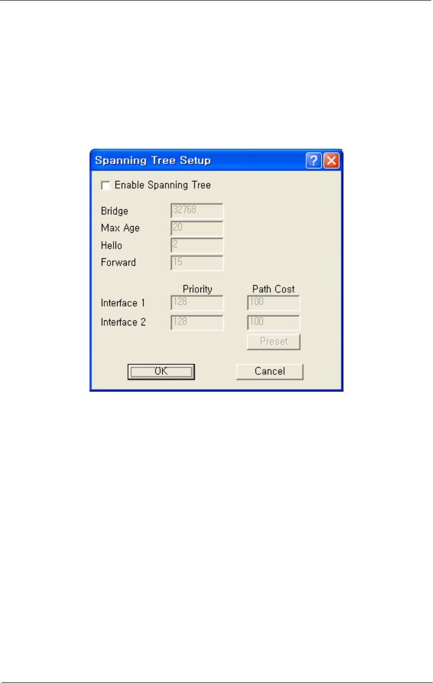
Spanning Tree Setup
The Spanning Tree Setup screen allows you to configure your bridges so
that they will dynamically discover a loop-free subset of the LAN
topology (a tree), that provides the most efficient level of connectivity
between every pair of physically connected Local Area Network
segments. See Spanning Tree for more information about how the
spanning tree algorithm works. The default settings for the Spanning
130
WLAN Cable Access Point 6220 NTPM99CA Rel 1.0 Issue 2 Nov 2004
Tree Algorithm will provide satisfactory performance for most Local
Area Network (LAN) topologies.
Enable Spanning Tree -- Select this checkbox if you wish to enable
Spanning Tree capabilities.
Figure 4-51
VLAN Spanning Tree Setup window
Bridge Priority -- The Bridge Priority parameter allows you to influence
the choice of the Root Bridge and Designated Bridge as calculated by the
Spanning Tree Algorithm.
Valid Values: 0 - 65000
Default: 32768
A low numerical value makes the bridge more likely to become the
designated bridge or root bridge (typically 0).
The recommended value is 32768.
You may assign a duplicate priority value to multiple bridges, provided
that it is a non-zero value. Bridges that have an identical Bridge Priority
level are typically not intended to function as the root bridge.
Max Age -- The Max Age parameter identifies the maximum age of
received Spanning Tree protocol information.

131
WLAN Cable Access Point 6220 NTPM99CA Rel 1.0 Issue 2 Nov 2004
When the bridge receives protocol information that exceeds the Max Age
value, the bridge will discard the information and start the Forward
Delay timer to allow other bridges to forward updated topology
information (for example, that another bridge has become the Root
Bridge).
Note: Recommended Value (20 seconds)
A low Max Age value occasionally may cause the Spanning Tree to
reconfigure unnecessarily, resulting in temporary loss of connectivity
throughout the network.
A high Max Age value will cause the LAN to take longer than necessary
to rebuild the Spanning Tree whenever a link or bridge unit breaks down
or becomes available again.
Hello Time -- The Spanning Tree Hello Time parameter identifies the
time interval between Configuration PBDU transmitted by a root bridge,
or a bridge that is attempting to become the root bridge.
Note: Recommended Value (2 seconds)
Shortening the Hello Time will make the protocol more robust,
especially when the probability of loss of configuration messages is high.
Lengthening the Hello Time will lower the overhead of the algorithm
since the interval between the transmissions of configuration messages
will be longer.
Forward -- The Forward Delay is a timer that prevents a bridge to
forward data packets when:
• The bridge receives information that the active Spanning Tree
topology must be updated (for example when a bridge breaks down
or when somebody modified the Bridge Priority or Path Cost value of
a particular bridge).
• The bridge registers that the protocol information exceeds the
specified Max Age value.
• Changes in the Spanning Tree topology must be communicated to all
bridges in the bridged network. The Forward Delay timer will
compensate for the propagation delays that occur in passing the
protocol information, allowing all bridges to close the old data paths,
before the new data paths are activated.
Note: Recommended Value (15 seconds)
A lower value may result in temporary loops as the Spanning Tree
Algorithm converges.

132
WLAN Cable Access Point 6220 NTPM99CA Rel 1.0 Issue 2 Nov 2004
A higher value may result in longer partitions after the Spanning Tree
reconfigures.
Port Priority-- Normally the Bridge Port priority in Spanning Tree
topologies is imposed by the Root Bridge and the applicable values of
the Path Cost to the Root Bridge.
When concurrent bridge ports of a single bridge unit are connected in a
loop, this parameter enables you to influence which port should be
included in the Spanning Tree.
Valid Values: 0 - 255
Default: 128
A lower value makes a port more likely to become selected in the
Spanning Tree than the concurrent one that has a higher numerical value.
A higher value makes a port less likely to be selected in the Spanning
Tree than a port with a lower numerical value.
Path Cost-- The Path Cost value is used to determine the preferred data
paths between bridges throughout the network and the root bridge.
The Root Bridge transmits BPDU messages throughout the Local Area
Network. When a bridge unit receives a BPDU message at one of its
ports, it will add the value in the Path Cost field for that port to the value
in the Root Path Cost Field of the BPDU message before forwarding the
message again. This will help the other bridges to determine the Total
Path Cost to the Root Bridge via this port.
Valid Values: 0 - 255
Default: 100
A lower Path Cost value would typically be used for ports to LAN
segments closer to the Root Bridge.
A higher Path Cost value would typically be used for ports to LAN
segments that are the "leafs" of the Spanning Tree.
For example, when using the Secure Data Mode Station as an access
point for wireless stations to the Ethernet, a high Path Cost for the
wireless interface will minimize unnecessary use of the bandwidth for
the wireless medium (recommended value 255).
When using Secure Data Mode Stations in a wireless point-to-point link
to interconnect two LAN segments, a low Path Cost for the wireless
interface will prioritize this link as compared to other physical links, such
as a leased line or low-bandwidth connections.
133
WLAN Cable Access Point 6220 NTPM99CA Rel 1.0 Issue 2 Nov 2004
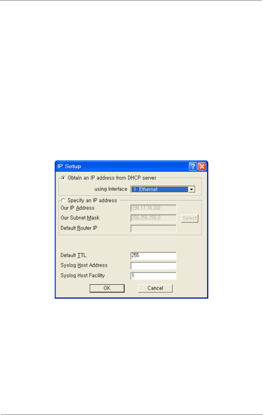
Set Up IP for APU and CSU
The IP Setup screen allows you to set the Secure Data Mode Station's IP
Addressing information. The Secure Data Mode Station must have an IP
address assigned to it if you wish to connect to it using the Configuration
tool, which makes use of SNMP to connect to the Secure Data Mode
Station.
Note: This screen is only available when the Enable IP Routing, Enable
Outgoing Network Address Translation, and Enable Incoming Network
Address Translation checkboxes been de-selected on the General Setup
screen.
Figure 4-52
IP Setup window
You can choose to set up the base station to obtain an IP address from
DHCP server. If you select this option, you must also choose the
interface on which you would like the base station to send the request.
This option causes your base station to send a broadcast request for its IP
address, subnet mask, and default router over the given interface at base
station startup time. If you select the DHCP option, it is recommended
(though not required) that you set up your DHCP server to always
provide the same IP address to this Secure Data Mode Station system.
You can also manually specify an IP Address to set the IP Address for
the base station yourself:

134
WLAN Cable Access Point 6220 NTPM99CA Rel 1.0 Issue 2 Nov 2004
You can set the life expectancy for packets originating from this Secure
Data Mode Station using the Default TTL (Time to Live) field.
You can use syslog messages to log information such as logins, service
errors and general configuration information. Since there is no storage
on a base station, a general purpose computer is needed to log these
messages. To set the syslog host that will accept syslog messages, use
the Syslog Host Address and Syslog Host Facility fields.
Obtain an IP Address from DHCP Server-- Select this radio button if
you wish to obtain an IP address from the DHCP Server.
If you select this option, you must also choose the interface on which
you would like the base station to send the request. This option causes
your base station to send a broadcast request
For its IP address, subnet mask, and default router over the given
interface at base station startup time. If you select the DHCP option, it is
recommended (though not required) that you set up your DHCP server to
always provide the same IP address to this Secure Data Mode Station
system.
Using Interfaces-- Select the interface for which you wish to obtain an
IP address. A base station has several network interfaces to which it may
be connected. The network interfaces are numbered (1, 2, 3...), and the
interface numbers may be found by selecting Interface Setup from the
Setup Menu.
Specify an IP Address-- Select this radio button if you wish to enter an
IP address manually.
Our IP Address-- This is the address of the Secure Data Mode
Bridge/Router itself. If you wish to configure or monitor your Secure
Data Mode Bridge/Router, or if your network supports IP and you wish
to enable the Ping support and IP/SNMP support of the Secure Data
Mode Bridge/Router, set this to a valid IP address. After setting this
address to 0.0.0.0, enter the IP address of the base station.
Please note that unless you enable IP Routing on the IP Router Setup
screen, the Bridge/Router is not an IP router. It has only one IP address,
and that address applies to both the remote and local networks (i.e., both
sides of the Bridge). Having two Ethernet interfaces with the same IP
address is different than a standard IP host, but is appropriate for a
Transparent Bridge. The Ethernet address of both interfaces is also the
same.

135
WLAN Cable Access Point 6220 NTPM99CA Rel 1.0 Issue 2 Nov 2004
Note: This field is only enabled when the Specify an IP Address radio
button has been selected.
Our Subnet Mask-- Enter the subnet mask for the base station.
Note: This field is only enabled when the Specify an IP Address radio
button has been selected.
Default Router IP-- Enter the IP address of the router.
Note: This field is only enabled when the Specify an IP Address radio
button has been selected.
Select Button-- Clicking this button displays the IP Mask List screen,
which allows you to select a particular IP mask.
IP Mask List-- The IP Mask List window displays a list of common IP
subnet masks for a given size IP subnet.
Default TTL-- The Time To Live (TTL) counter avoids endless
forwarding of message frames with incorrect addressing by defining a
maximum number of hops a packet can take. Each time the frame is
forwarded by a router, the TTL counter decreases by one.
When the TTL = 0, the frame is rejected.
Syslog Host Address-- Syslog messages can be used to log information
such as logins, service errors and general configuration information.
Since there is no storage on a base station, a general purpose computer is
needed to log these messages.
The Syslog Host Address is the IP Address of the system which accepts
"syslog" system logging packets from the base station.
Syslog Host Facility
Syslog messages can be used to log information such as logins, service
errors and general configuration information. Since there is no storage
on a base station, a general purpose computer is needed to log these
messages.
The Syslog Host Facility describes the part of the system generating the
syslog message, and in UNIX-based systems usually uses one of the
following keywords: auth, authpriv, cron, daemon, kern, lpr, mail, mark,
news, syslog, user, uucp, and local0 through local7.
The base station is capable of sending messages using the local0-local7
facilities. Enter the correct syslog facility number (0-7) that corresponds
to the local facility type on your syslog host.
136
WLAN Cable Access Point 6220 NTPM99CA Rel 1.0 Issue 2 Nov 2004
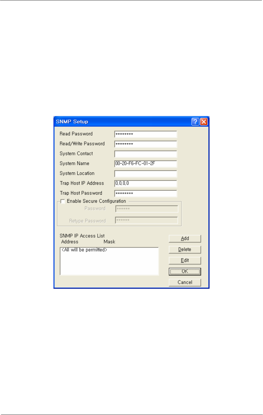
Set Up SNMP
The SNMP Setup screen allows you to manage a network environment
that includes multiple base stations where you can use the Simple
Network Management Protocol (SNMP).
SNMP setup allows you to create multiple authorization levels for
network management that are password protected.
Figure 4-53
SNMP Setup window
Read Password-- This password enables you to create a network
management level where a local LAN Administrator can view, but not
modify, the SNMP parameters.
Read/Write Password-- This password enables you to create a network
management level where only a Network Supervisor knowing the right
Read/Write password will be able to view or modify the SNMP
parameters.
Contact-- Optionally, enter the name or address of the Network
Administrator.

137
WLAN Cable Access Point 6220 NTPM99CA Rel 1.0 Issue 2 Nov 2004
System Name-- Optionally, enter the logical location of a base station
(for example, the network segment to which the base station has been
connected).
System Location-- The optional field to identify the physical location of
a base station. For example, the building or room where the base station
is located at
Trap Host IP Address-- The IP Address of the network management
station that collects the SNMP Trap messages.
The Trap Host is the station in an SNMP managed network where SNMP
trap messages are collected. Trap messages are sent to the trap host when
certain events occur, such as rebooting.
Trap Host Password-- The Trap Host is the station in a SNMP managed
network where SNMP trap messages are collected. Trap messages are
sent to the trap host when certain events occur, such as rebooting.
Enter a password that corresponds to the password set at the Trap Host to
filter unsolicited or unauthorized SNMP Trap messages at the Trap Host.
The Trap Host IP Password will be embedded in the SNMP Trap
messages sent by this base station. If the Trap Host receives a message
without or with an unknown password, the Trap message will be ignored.
SNMP IP Access List-- The SNMP IP Access List displays the IP
addresses and subnet masks of those stations that you have designated as
stations that will manage networks using SNMP.
In addition to the Read and Read/Write passwords, you can use the
SNMP Access List to prevent unauthorized users from modifying the
SNMP setup of your base stations.
The SNMP IP Access List enables you to authorize SNMP management
to a restricted group of SNMP Management stations identified by:
The unique IP address of the Management Station(s)
The interfaces via which the base station will be accessed.
Click the Add button to display the Input SNMP Access List to add new
IP addresses to the list.
138
WLAN Cable Access Point 6220 NTPM99CA Rel 1.0 Issue 2 Nov 2004
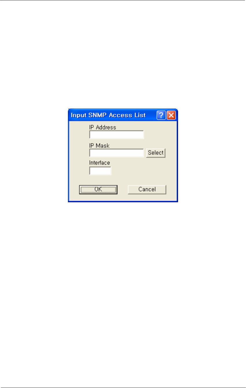
Input SNMP Access List Dialog - Overview
Clicking the Add button displays the SNMP Access List Dialog, which
allows you to enter the IP addresses and subnet masks of those stations
that you have designated as stations that will manage networks using
SNMP.
Figure 4-54
Input SNMP Setup window
IP Address-- The unique IP address of the SNMP management station
you wish to add or edit.
IP Mask-- Enter the Subnet mask, or clicks the Select button to display
the IP Mask List and select a mask from the list.
Note: A subnet mask value of 255.255.255.255 will authorize only the
station with the address specified in the IP address. A subnet mask value
of 255.255.255.0 will authorize all stations that have an IP address
within the range of that particular subnet (the IP address field will
display the value xxx.xxx.xxx.0).
Warning: The subnet mask value 0.0.0.0 will authorize any station to
view or modify SNMP IP setup of the base station via the interface
identified in the Interface field.
Interface-- The number of the interfaces over which packets on this
route is sent.
Select Button-- Clicking this button displays the IP Mask List screen,
which allows you to select a particular IP mask.
139
WLAN Cable Access Point 6220 NTPM99CA Rel 1.0 Issue 2 Nov 2004
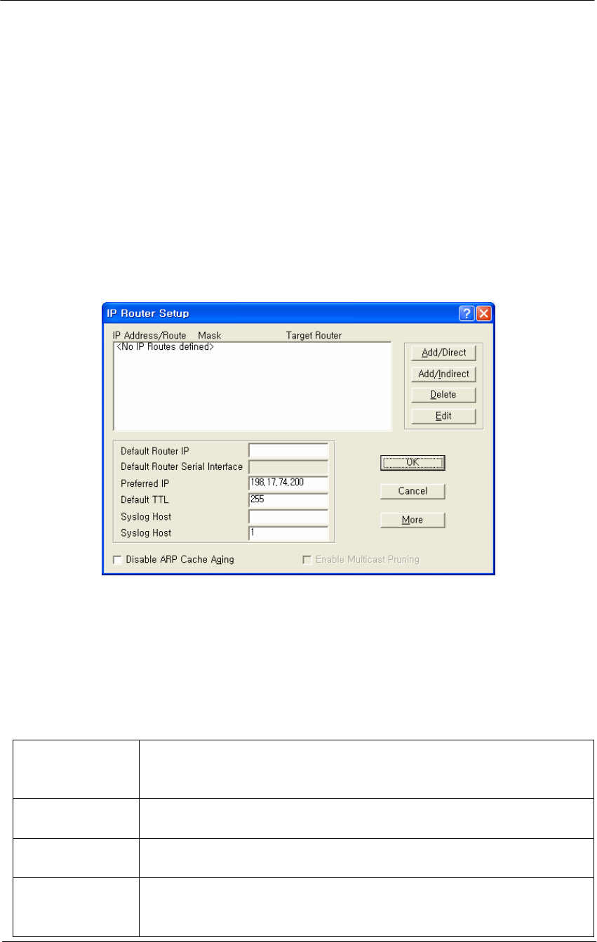
Set Up IP Routing
The IP Router Setup screen is used to set up IP Routing. This enables the
base station to send IP packets to the appropriate subnet or router. Once
you have set up the basic IP Router configuration, you may also want to
set up the following optional components:
Note: This option is only available if the Enable IP Routing checkbox
on the General Setup screen has been selected.
Figure 4-55
IP Router Setup window
IP Route List
This pane displays the list of IP Routes that this Router has been
configured to use. To add additional direct or indirect routes, click on the
Add/Direct or Add/Indirect buttons.
Table 4-6
IP Route List
IP Route List
This pane displays the list of IP Routes that this Router has been
configured to use. To add additional direct or indirect routes,
click on the Add/Direct or Add/Indirect buttons.
Mask The Subnet Mask of the IP Address, which shows which
addresses should be routed using this route.
Target For a Direct Route, the word Direct appears in this field. For an
Indirect Route, this field shows the Default Router.
Interface/Cost For direct routes, the interface to use when sending packets
using this route. For indirect routes, the cost metric of using this
route (used to determine the best route to use for a given packet).

140
WLAN Cable Access Point 6220 NTPM99CA Rel 1.0 Issue 2 Nov 2004
Default Router IP Address-- Enter the IP Address of the router that the
base station should use to communicate with networked devices outside
its current subnet.
Default Router Serial Interface-- The Secure Data Mode station has
several network interfaces to which it may be connected. An interface
number is required for the Secure Data Mode station to know which
interface to use to send packets addressed to a given destination. This
field displays the serial interface that the router will use by default.
Preferred IP Address-- From time to time, the Secure Data Mode
Bridge/Router will transmit unsolicited IP packets such as SNMP traps,
Syslog, RIP, or IP/ARP packets. Most routers randomly use one of the IP
addresses from one of the router interfaces as the source IP address for
these packets. However, in the Preferred IP Address field, you can
specify the source IP address that you prefer to use for these packets.
Default TTL-- The Time To Live (TTL) counter avoids endless
forwarding of message frames with incorrect addressing by defining a
maximum number of hops a packet can take. Each time the frame is
forwarded by a router, the TTL counter decreases by one. When the TTL
= 0, the frame is rejected.
Syslog Host Address-- Syslog messages can be used to log information
such as logins, service errors and general configuration information.
Since there is no storage on a base station, a general purpose computer is
needed to log these messages.
The Syslog Host Address is the IP Address of the system that accepts
"syslog" system logging packets from the base station.
Syslog Host Facility-- Syslog messages can be used to log information
such as logins, service errors and general configuration information.
Since there is no storage on a base station, a general purpose computer is
needed to log these messages.
The Syslog Host Facility describes the part of the system generating the
syslog message, and in UNIX-based systems usually uses one of the
following keywords: auth, authpriv, cron, daemon, kern, lpr, mail, mark,
news, syslog, user, uucp, and local0 through local7.
The base station is capable of sending messages using the local0-local7
facilities. Enter the correct syslog facility number (0-7) that corresponds
to the local facility type on your syslog host.
Disable ARP Cache Aging-- Select this checkbox to stop the Address
Resolution Protocol (ARP) table from removing entries after a certain

141
WLAN Cable Access Point 6220 NTPM99CA Rel 1.0 Issue 2 Nov 2004
period of time. The IP ARP table relates each (wired or wireless)
station's IP address to its physical MAC Address so the base station
knows how to address Ethernet messages bound for a particular IP
Address. If you disable (uncheck) ARP cache aging, the base station will
not remove entries from this table, and it may fill up over time. The base
station can hold up to 10,000 entries in the ARP table.
Enable Multicast Pruning-- Select this checkbox if you want to enable
multicast pruning.
IP multicast is a bandwidth-conserving technology that reduces traffic by
simultaneously delivering a single stream of information to potentially
thousands of corporate recipients and homes.
Without multicast pruning, multicast traffic is treated in the same manner
as broadcast traffic. That is, it is forwarded to all ports. However, with
multicast pruning, you choose to permit only the packets that are a part
of multicast group in your network. Multicast pruning generates no
additional network traffic, allowing you to significantly reduce multicast
traffic passing through your switch.
Add Direct IP Routes
Clicking the Add/Direct button displays the Add Direct IP Route screen,
which allows you to add new direct IP routes.
When the Secure Data Mode station has two or more IP subnets directly
attached to its different interfaces, it can route IP packets between those
subnets using a direct route. This screen is used to specify the direct
routes for each of the interfaces on the Secure Data Mode Bridge/Router.
A direct route consists of an IP address, which specifies the basic IP
address to route, a Subnet Mask which defines the basic class of IP
addresses that will be routed, and an interface number which specifies
where the IP subnet is attached. When IP packets addressed to a system
arrives at the Secure Data Mode station, the Secure Data Mode station
will send it directly to the target machine on the interface specified.
Figure 4-56
Direct IP Route Setup window

142
WLAN Cable Access Point 6220 NTPM99CA Rel 1.0 Issue 2 Nov 2004
IP Address-- The IP address specifies the basic IP address to route.
IP Mask-- The Subnet Mask which defines the basic class of IP
addresses that will be routed. Clicking the Select button displays the IP
Mask List, which the shows the IP Masks that can be used as public or
private IP masks for IP routing. The list consists of all possible subnet
masks, and represents the range of addresses that will be translated.
Interface-- An interface number specifies where the IP subnet is
attached.
Add Indirect IP Routes
The Add Indirect IP Route screen is used to add indirect IP routes.
When the base station needs to send IP packets between IP subnets
which are not directly connected to one of its interfaces (i.e., not on the
same network segment), it must have an indirect route for sending those
packets.
An indirect route consists of:
An IP Address which specifies the basic IP address to route,
A Subnet Mask which defines the class of IP addresses that will be
routed,
A Target Router that will relay the IP packet, and
A Cost value, which specifies the number of "hops" required for the
indirect route.
When an IP packet addressed to a system on the indirectly routed subnet
arrives at the base station, the base station will route it over the interface
specified to the Target Router to be further routed.
Figure 4-57
Indirect IP Route Setup window
143
WLAN Cable Access Point 6220 NTPM99CA Rel 1.0 Issue 2 Nov 2004
IP Address-- The IP Address which specifies the basic IP address to
route.
IP Mask-- Enter the IP subnet mask for the IP address to be routed, or
click the Select button and choose a subnet mask from the list. Clicking
the Select button displays the IP Mask List, which the shows the IP
Masks that can be used as public or private IP masks for IP routing. The
list consists of all possible subnet masks, and represents the range of
addresses that will be translated.
Target Router-- Enter the IP address of the router that you wish to use
as the target router.
A target router is the IP address of the router that knows how to handle
the IP packet that is being routed. When used in indirect routes, it could
specify the router that is attached directly to the subnet of the packet's
final destination, or a router that knows where to send it.
Cost-- The cost value reflects the number of "hops" required for the
connection. The default value of 1 indicates that only one "hop" is
required. The lower the cost value, the more likely that route will be
chosen.
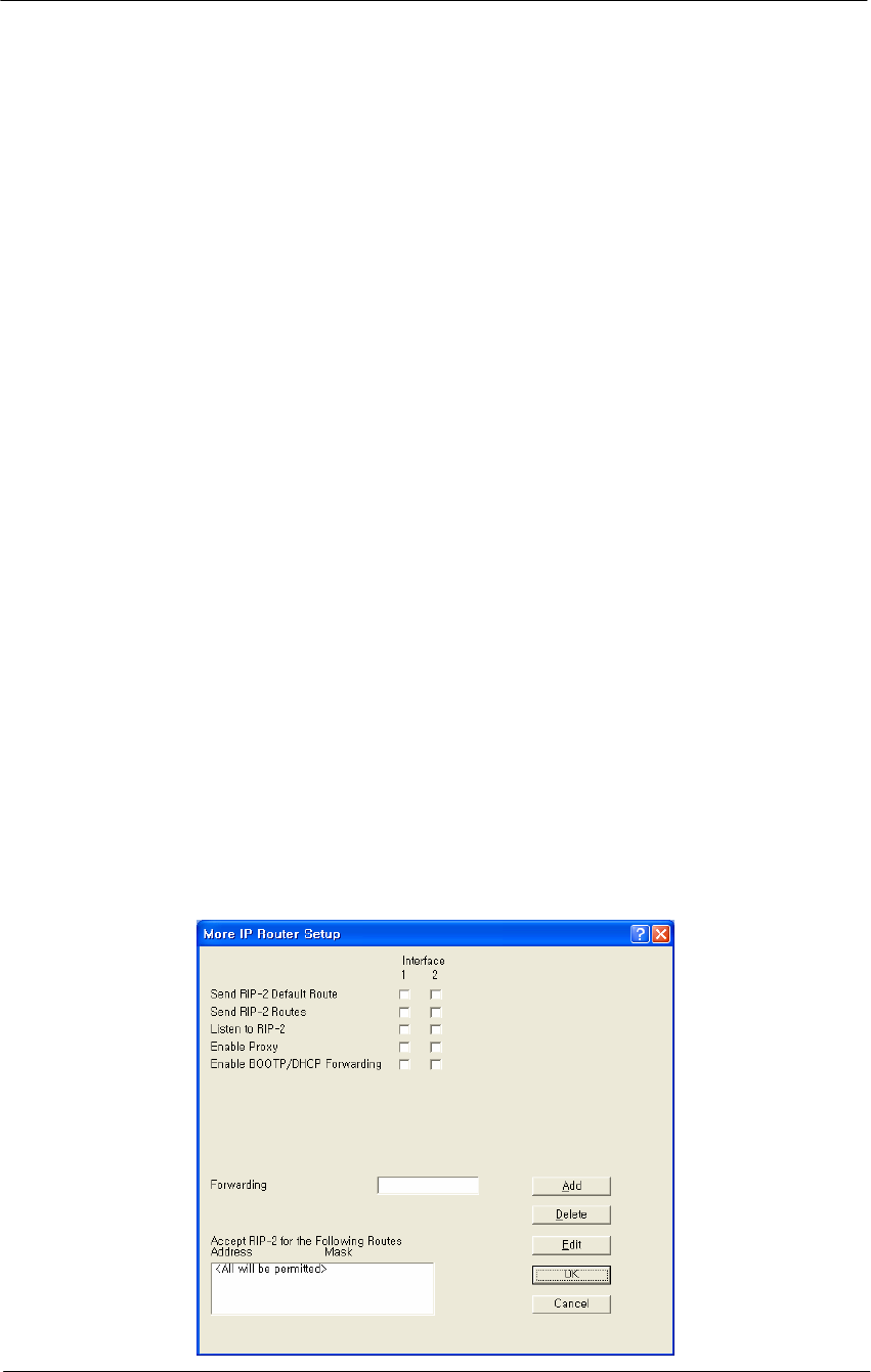
Advanced IP Routing Setup
The More IP Router Setup screen is used to set up advanced IP router
interfaces.
Figure 4-58
Advanced IP Routing Setup window

144
WLAN Cable Access Point 6220 NTPM99CA Rel 1.0 Issue 2 Nov 2004
Send RIP-2 Default Route-- If the base station sends the Routing
Information Protocol (RIP) default route (0.0.0.0) to other routers and
hosts attached to a particular interface, select that interface's checkbox on
the Send RIP Default Route line. By default, the base station will not
send the Default Route on a particular interface unless this box is
checked.
In the example shown in the screenshot, the base station will send RIP
routes only on interfaces 1 and 2.
Send RIP-2 Routes -- If the base station should SEND Routing
Information Protocol (RIP) Routes for routes of which it has knowledge
to other routers on a particular interface, select that interface's checkbox
on the Send RIP Routes line. By default, the base station will not send
RIP Routes on a particular interface unless this box is checked.
For the given example, the base station will send RIP Routes only on
interface 1.
Listen to RIP-2-- If the base station should ACCEPT Routing
Information Protocol (RIP) routes from other routers on a particular
interface, select that interface's checkbox on the Listen to RIP line. By
default, the Secure Data Mode Station will not accept RIP Routes from
other routers, so you must select the interfaces if you wish to listen to
RIP. For the given example, the Secure Data Mode Station will listen to
RIP Routes on Interfaces 1 and 2, but will not accept RIP routes sent to it
on interface 3.
Enable Proxy ARP-- Enabling Proxy ARP for a particular interface tells
the base station that when it receives an ARP request for a particular
client connected by that interface, that the base station itself should
respond to the ARP Request, fulfilling the request with information that
is in its IP ARP Table.
For example, Proxy ARP is enabled on interface 2. The IP ARP Table
contains (among others) the following entry:
Table 4-7
IP ARP Table
Interface Physical Address IP Address Media Type
2 00:60:1d:04:4d:88 10.7.3.5 dynamic
Since Proxy ARP is enabled for interface 2, when the base station
receives a broadcast ARP Request for 10.7.3.5, instead of passing the
ARP on to 10.7.3.5, the base station will answer the request with

145
WLAN Cable Access Point 6220 NTPM99CA Rel 1.0 Issue 2 Nov 2004
information its own IP ARP table, that is: IP Address 10.7.3.5 -> MAC
Address 00:60:1d:04:4d:88.
Proxy ARP is useful in many situations to reduce unnecessary network
traffic, but is especially useful when you have clients in power-save
mode, to prevent them from being 'woken up' whenever an ARP is done.
Enable BOOTP/DHCP Forwarding -- Select the interfaces for which
you would like the base station to forward BOOTP and DHCP requests
on to the BOOTP/DHCP server, which is specified in 'Forwarding Host’.
Forwarding BOOTP and DHCP requests is necessary when the
BOOTP/DHCP clients are not on the same IP subnet as the
BOOTP/DHCP server.
If you are using BOOTP/DHCP, forwarding should most likely be
DISABLED for the interface through which the BOOTP/DHCP server is
located, and ENABLED for the other interfaces.
In the displayed screen, the BOOTP/DHCP Server is located via
interface 1, so forwarding is enabled for interfaces 2 and 3, since clients
on interfaces 2 and 3 have no other way of accessing the BOOTP/DHCP
server.
Forwarding Host -- If you have enabled BOOTP/DHCP forwarding for
one or more interfaces, enter the IP address of the BOOTP/DHCP server
or relay agent to which you should forward BOOTP/DHCP requests.
In this example, the BOOTP/DHCP Forwarding host is 10.2.3.1.
Accept RIP-2 for the Following Routes-- In addition to the other
Advanced IP Router features which allow you to accept RIP routes from
particular interfaces, you can specify which RIP Routes you would like
to accept. You are also able to specify the interfaces from which you
would like to accept those particular RIP Routes.
The base station will accept RIP only for three particular routes. In the
More IP Router Setup screen, it was specified that the base station should
listen to RIP Routes on interfaces 1 and 2. This section further specifies
that the base station should listen to the following RIP Routes ONLY:
10.17.42.0 (mask 255.255.255.0) only if it comes from interface 1
10.20.24.0 (mask 255.255.248.0) only if it comes from interface 2
10.220.23.0 (mask 255.255.255.0) on any interface
All other RIP routes will be ignored.
146
WLAN Cable Access Point 6220 NTPM99CA Rel 1.0 Issue 2 Nov 2004
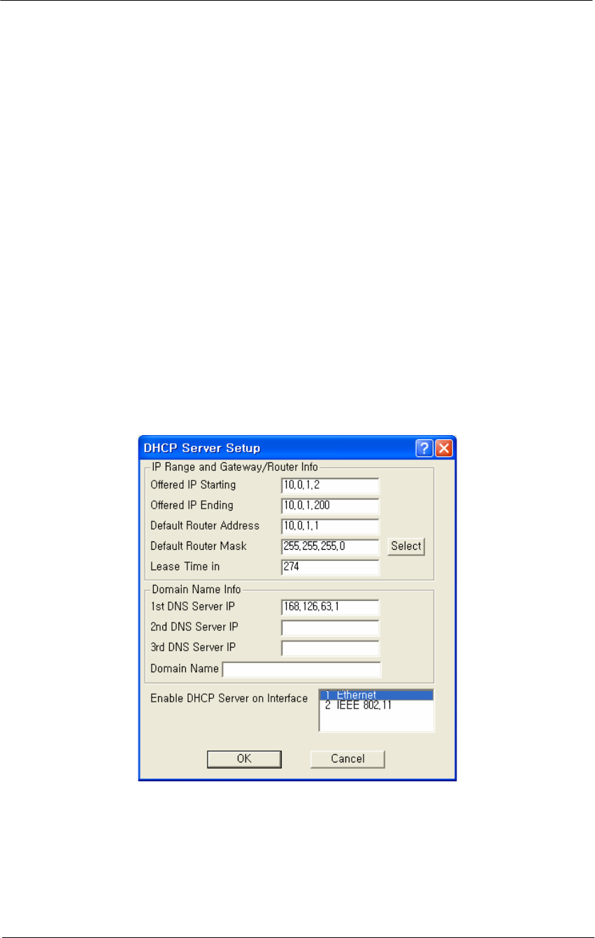
DHCP Server Setup
The DHCP Server Setup screen is used to set up the base station's
Dynamic Host Configuration Protocol (DHCP) Server feature. The
DHCP Server feature is a basic DHCP Server that can enable any and all
wireless (or other) clients that connect to the base station to obtain their
IP Address information from this Secure Data Mode.
Warning: If you have set up the base station to Obtain IP Address from
DHCP Server on the IP Host Setup screen, do not enter anything in the
Domain Name Info section of this screen. When the base station gets its
own IP Address by DHCP, it will automatically determine the correct
Domain Name information. You should, however, set up the IP Range
and Gateway/Router Info section and select the correct interface.
Note: This screen is only available when the Enable DHCP Server
checkbox has been selected on the General Setup screen.
Figure 4-59
DHCP Server Setup window
Offered IP Address-- Enter the beginning and ending IP addresses for
the IP address range that the Secure Data Mode Station should offer to
DHCP clients. When DHCP requests are received by the Secure Data
Mode Station, it will offer the IP Starting Address to the first client, and
increment the IP address offered to each consequent DHCP client until it
reaches the IP Ending Address. IP Address leases must be renewed by

147
WLAN Cable Access Point 6220 NTPM99CA Rel 1.0 Issue 2 Nov 2004
the DHCP client within the given Lease Time, or the IP Address will be
made available to another client.
Note: The Secure Data Mode Station does NOT store DHCP address
assignments between restarts. If the Secure Data Mode Station is
rebooted, it will ARP for each address in the provided address range,
recording which client is using which IP address.
Note: Be careful not to include the default router's IP address in the
Offered IP Address range.
Default Router Address-- Enter the default router IP address for the
Secure Data Mode Station's DHCP clients.
Note: The default router IP address must be outside of the range defined
by the Offered IP Starting Address and Offered IP Ending Address.
Default Router Mask-- Enter the subnet mask for the default router, or
click the Select button to display the IP Mask List, and select a subnet
mask from the list.
Lease Time in Minutes-- A DHCP lease is the amount of time that the
DHCP server grants permission to the DHCP client to use a particular IP
address. Enter the lease time (in minutes) for your DHCP server.
DNS Server IP Addresses-- Enter the IP address for the DNS server.
Warning: If you have set up the base station to Obtain IP Address from
DHCP Server on the IP Host Setup screen, do not enter any DNS server
IP addresses or a domain name. When the base station gets its own IP
Address by DHCP, it will automatically determine the correct Domain
Name information. You should, however, set up the IP Range (IP
starting and ending addresses) and Gateway/Router Info section and
select the correct interface.
Domain Name-- Enter the name of the domain.
Warning: If you have set up the base station to obtain IP Address from
DHCP Server on the IP Host Setup screen, do not enter any DNS server
IP addresses or a domain name. When the base station gets its own IP
Address by DHCP, it will automatically determine the correct Domain
Name information. You should, however, set up the IP Range (IP
starting and ending addresses) and Gateway/Router Info section and
select the correct interface.
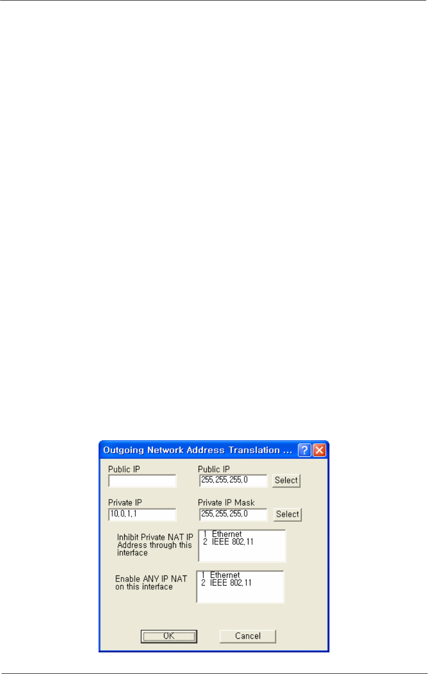
148
WLAN Cable Access Point 6220 NTPM99CA Rel 1.0 Issue 2 Nov 2004
Enable DHCP Server on Interface-- Select the interface on which you
wish to enable the DHCP server.
Set Up Outgoing Network Address Translation (NAT)
Outgoing Network Address Translation (NAT) allows multiple
computers to share a single IP address to connect to an IP network,
including the Internet. This allows homes, small businesses, and Internet
Service Providers to have Internet service for all of their computers
without having to pay for additional IP addresses. The NAT feature
serves as a simple firewall for incoming connections, since only traffic
initiated by an interior computer is permitted through the NAT.
In the screen shown below, when the client 10.0.1.1 wants to send data to
the Internet, the access point will take the packet, replace the return
address of 10.0.1.1 with 140.254.5.147, and then send the packet to the
Internet. When a response comes from the Internet, the access point
sends it to the correct client in the local address space.
Note: This screen is only available when the Enable Outgoing NAT
checkbox has been selected on the General Setup screen.
Note: You do not need to turn on Outgoing NAT if you are using
Incoming NAT, and vice versa. Incoming NAT only needs to be
configured if servers in the local (private) address space need to connect
with clients in the global (public) address space.
Figure 4-60
Outgoing NAT Setup window

149
WLAN Cable Access Point 6220 NTPM99CA Rel 1.0 Issue 2 Nov 2004
Public IP Address-- The IP address/mask seen by the external network.
Note: The IP address and subnet mask must be the same as the one in the
IP Setup dialog under the Setup menu.
Public IP Mask-- The IP mask seen by the external network.
Note: The IP address and subnet mask must be the same as the one in the
IP Setup dialog under the Setup menu.
Select IP Mask Button-- Clicking this button displays the IP Mask List,
which the shows the IP Masks that can be used as public or private IP
masks for outgoing NAT. The list consists of all possible subnet masks,
and represents the range of addresses that will be translated.
Private IP Address-- The IP address that is seen by the local/internal
network.
Note: The IP will be combined with the subnet mask, and the range of
addresses that results will be translated. This range of IP set must match
the addresses of the clients that connect to the base station.
Private IP Mask-- The IP mask that is seen by the local/internal network.
Note: The IP will be combined with the subnet mask, and the range of
addresses that results will be translated. This range of IP set must match
the addresses of the clients that connect to the base station.
Inhibit Private NAT IP Address through this interface
This option allows you to select one or more interfaces in which NAT
will not be permitted. By default, no interfaces are selected. To select
more than one interface, hold down the <Ctrl> key and click the names
of the interfaces you wish to inhibit. Typically, you will inhibit the
public interfaces because you will generally have users behind the
private side (i.e., the private side is NATed to the public side).
Therefore, you must inhibit the interface used on the public side,
whichever it may be. For example, in the screen shown below, the
Ethernet 10.* network is NATed to the 140.* public wireless network.
Therefore, NAT must be inhibited on the public interface, in this case the
802.11b interface. To do this, you would select 802.11b from the list, and
click the OK button.
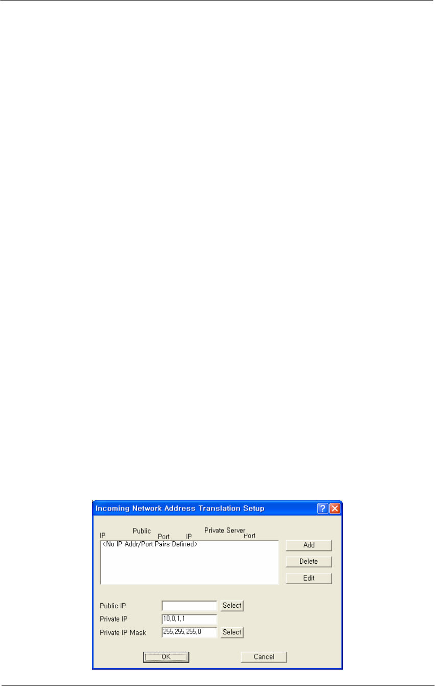
150
WLAN Cable Access Point 6220 NTPM99CA Rel 1.0 Issue 2 Nov 2004
Set Up Incoming Network Address Translation (NAT)
Incoming Network Address Translations (NAT) is used to redirect
requests to servers in the local address space based on the port of the
request. If, for example, the client at local address 10.0.1.2 is serving
web pages, and a request comes to the access point on that port for a web
session, then the request will be forwarded to the web server on 10.0.1.2.
The server will respond with the web page to the address of the original
request.
Note: This screen is only available when the Enable Incoming NAT
checkbox has been selected on the General Setup screen.
Note: Incoming NAT only needs to be configured if servers in the local
(private) address space need to connect with clients in the global (public)
address space. You do not need to turn on Incoming NAT if you are
using Outgoing NAT, and vice versa.
To set up incoming NAT:
1. From the Setup tab, select General Setup. The General Setup screen
is displayed.
2. Make sure that the Enable IP Routing checkbox is unchecked.
3. Select the Enable Incoming Network Address Translation checkbox,
and then click OK to close the General Setup screen.
4. Click the Incoming NAT button on the Setup tab. The Incoming
Network Address Translation Setup screen is displayed, and any
public and private IP address/port pairs that you have previously
defined are displayed in the window.
Figure 4-61
Incoming NAT Setup window

151
WLAN Cable Access Point 6220 NTPM99CA Rel 1.0 Issue 2 Nov 2004
IP Addresses/Ports-- This window displays the public and private IP
address/port pairs that you have previously defined.
Public IP Mask-- The public subnet mask for your local (internal)
servers in the dialog. The public IP mask is paired with the Public IP
address on the Input IP Address screen, as shown in the screens below.
Note: The public IP Mask must be the same subnet mask that was used
in the setup of the external (or global) address of the base station.
Private IP Address-- The private IP address for your local (internal)
servers in the dialog.
Note: The Private IP Address must be the same as the address and subnet
mask that was selected for your internal network.
Private IP Mask-- The private subnet mask for your local (internal)
servers in the dialog.
Note: The private IP Mask must be the same as the subnet mask that was
selected for your internal network.
Add IP Address/Port Pairs-- Clicking the Add button displays the Add
IP Address/Port Pair screen is used to add new pairs of incoming ports,
and the IP address to which they should be directed.
Figure 4-62
Input IP address/Port (NAT) Setup window
Public IP Address-- The public IP address for the service you wish to
use. On the incoming NAT, there can only be one public address. You
can map ports to specific local servers, but you must use the same public
IP address, as configured on the incoming NAT screen.

152
WLAN Cable Access Point 6220 NTPM99CA Rel 1.0 Issue 2 Nov 2004
Note: The Public IP address is paired with the Public IP mask on the
Incoming Network Address Setup screen, as shown in the screenshots
below.
Public Port-- The public port for the service you wish to use. For a
discussion of the ports on which well known services run, see
http://www.tatanka.com/doc/technote/tn0081.htm.
Note: The public IP address must be the same for different local servers,
but the port will be different (e.g. different ports for SMTP, FTP, web
servers, etc.).
Private Server IP Address-- The local (private) IP address of the server
to which the request should be forwarded.
Private Server Port-- The local (private) port on the server to which the
request should be forwarded.
Set up IP/UDP/TCP Filters-- Select the Firewall option from the Setup
Tab to set up the IP TCP/UDP firewall (filtering) features.
IP Firewalls are used to restrict access between (sub) networks to certain
IP hosts, types of IP packets, or connections to certain ports. You can set
up the firewall to completely block all external IP traffic, or restrict
access to certain machines, ports, or packet types.
Note: You must select the Enable IP/TCP/UDP Security Filters
checkbox on the General Setup screen in order to access this screen.
Remote IP Address and Mask-- This column of the TCP/UDP Filter
List displays the IP Address and Subnet Mask of the (un-trusted) remote
sub network or machine for which you have chosen to set up this IP
UDP/TCP filter.
Local IP Address and Mask-- This column of the TCP/UDP Filter List
displays the IP Address and Subnet Mask of the local sub network or
machine that is being protected by this particular firewall filter.
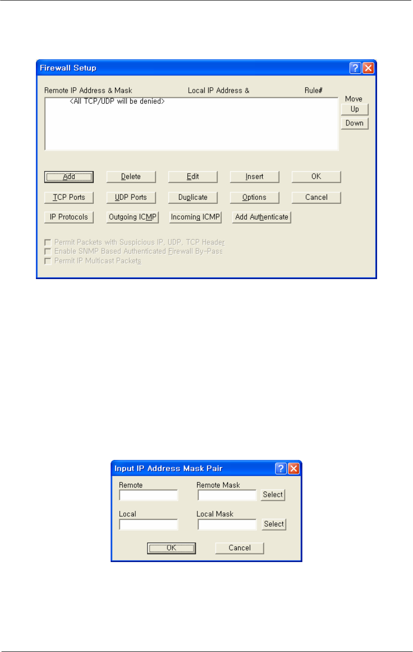
153
WLAN Cable Access Point 6220 NTPM99CA Rel 1.0 Issue 2 Nov 2004
Figure 4-63
Firewall Setup window
Add/Edit IP Address Mask Pair
The Add/Edit IP Address Mask Pair screen is used to enter both the IP
Address and Subnet Mask of both the local network (or machine) you
would like to protect and the remote network (or host) you would like to
protect it from.
A particular filter is applied only to traffic between the specific local and
remote networks (or hosts) shown in the list. If you wish to filter all
traffic, set the Remote IP Address and Subnet Mask both to '0.0.0.0'.
Figure 4-64
Input IP address (Firewall) Setup window
TCP Security Filters
To set the TCP ports to which a given filter will be applied, select the
filter you want to modify in the TCP/UDP Filter List and click the TCP
Ports button.
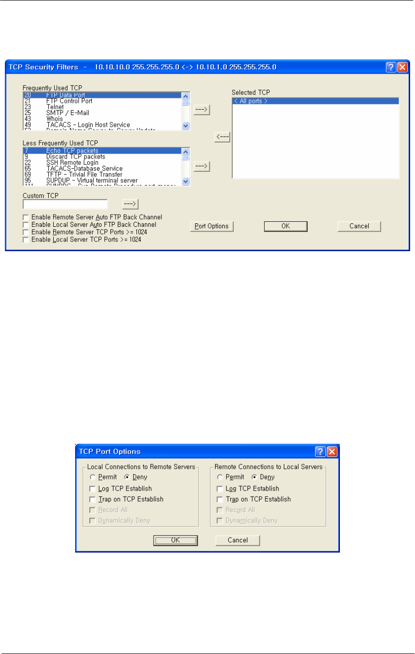
154
WLAN Cable Access Point 6220 NTPM99CA Rel 1.0 Issue 2 Nov 2004
Figure 4-65
TCP Security Filter Setup window
TCP Port Options
Clicking the Port Options button on the TCP Security Filter screen
displays the TCP Port Options screen. To set how the firewall filter is
applied for a given port, select the port (or the line labeled 'All other
ports') from the Selected TCP Ports list, and click on the 'Port Options'
button. This will display the window below, which you can click on for
more information. If you select the line 'All Other Ports' and then click
the 'Port Options' button, you will see a screen similar to the one
described in the UDP Port Options screen.
Figure 4-66
TCP Port Options Setup window
UDP Port Filters
To set the UDP ports to which a given filter will be applied, select the
filter you want to modify in the TCP/UDP Filter List and click the 'UDP
Ports' button.
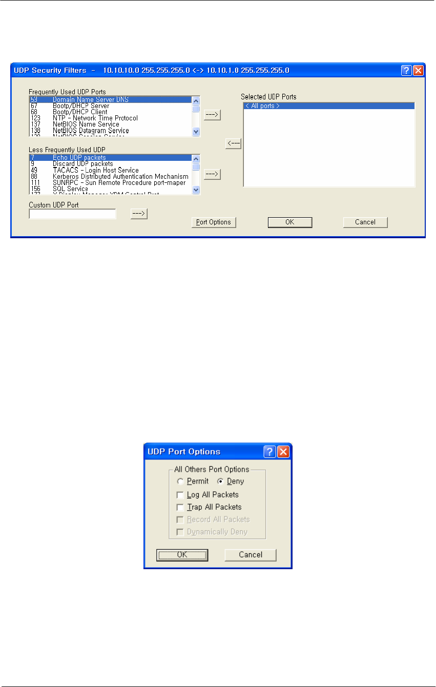
155
WLAN Cable Access Point 6220 NTPM99CA Rel 1.0 Issue 2 Nov 2004
Figure 4-67
UDP Port Options Setup window
UDP Port Options
Clicking the Portion Options button on the UDP Security Filters screen
displays the UDP Port Options screen. To set how the firewall filter is
applied for a given port, select the port (or the line labeled 'All other
ports') from the Selected UDP Ports list, and click on the 'Port Options'
button. The window displayed below is for the 'All Other Ports' line,
which sets the filter settings for all ports not explicitly listed in the
Selected UDP Ports list. See TCP Port Options for an example using a
specific port.
Figure 4-68
UDP Port Options Setup window
Firewall Setup Options
The Firewall Setup Options screen allows you to set handling options for
a particular filter. Select the filter from the list on the Firewall Setup
screen, and then click the Options button to display the following options.
Alternately, you can simply double click the filter in the list to display
the Firewall Setup Options screen.
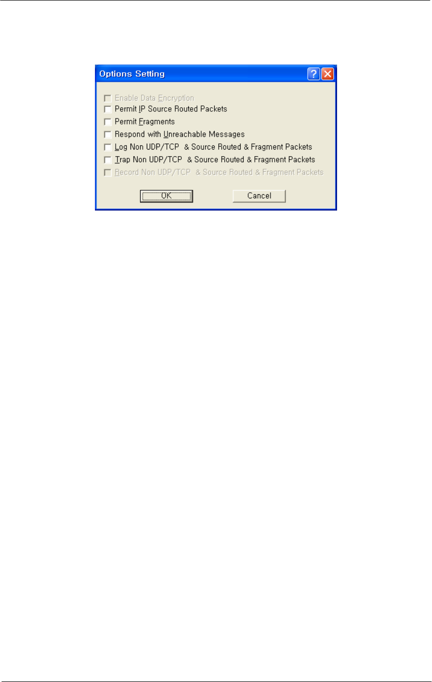
156
WLAN Cable Access Point 6220 NTPM99CA Rel 1.0 Issue 2 Nov 2004
Figure 4-69
Firewall Option Setup window
Enable Data Encryption-- Select this option if you wish to enable the
data in packets sent between the IP hosts or subnets specified in this filter
to be encrypted/decrypted by the Secure Data Mode Station. This option
is not available if Data Encryption is not enabled on the General Setup
screen.
Permit Non UDP/TCP Packets-- Select this option if you would like
the Secure Data Mode Station to allow IP packets that are neither TCP
nor UDP, such as ICMP. The firewall does not have specific filters for IP
protocols other than TCP, UDP, and ICMP. If you want to deny other
relatively rare protocols, do not select this checkbox.
Permit IP Source Routed Packets-- Select this option if you want the
Secure Data Mode Station to allow Source-Routed IP packets to the local
hosts protected by this filter. Source-Routed packets contain routing
information inside the packet headers, instead of allowing network
routers to decide the best route for the packet. They are primarily used in
network troubleshooting, but may be used to 'fool' the firewall that the
packets are coming from a trusted host. We strongly recommend that you
do not permit source routed packets.
Permit Fragments-- Select this option if you would like the Secure Data
Mode Station to permit fragmented IP packets to be passed through the
firewall. IP packets may be incorrectly fragmented, creating security
problems for hosts that may not properly handle incorrectly fragmented
IP packets.
Respond with Unreachable Messages-- Select this option if you want
the Secure Data Mode Station to respond to remote hosts attempting to
connect to local machines with Destination Unreachable messages when
the connection is denied by this security filter.
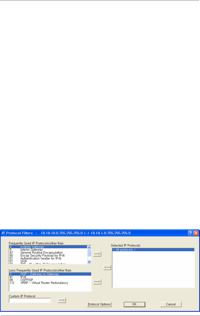
157
WLAN Cable Access Point 6220 NTPM99CA Rel 1.0 Issue 2 Nov 2004
Log Non UDP/TCP & Source Routed & Fragment Packets-- Select
this option if you want to log to the syslog for all packets that are not
UDP/TCP, are source-routed, or are fragmented.
Trap Non UDP/TCP & Source Routed & Fragment Packets-- Select
this option if you want the Secure Data Mode Station to SNMP Trap
messages whenever a non-TCP or non-UDP, Source Routed, or
Fragmented IP packet is received by the Secure Data Mode Station.
SNMP Traps are sent to the SNMP Trap Host specified in SNMP Setup.
Record Non UDP/TCP & Source Routed & Fragment Packets--
Select this option if you want the Secure Data Mode Station to record all
packets that are not UDP/TCP, are source-routed, or are fragmented.
IP Protocol Filters
Clicking the IP Protocols button displays the IP Protocol Filters screen,
which allows you to set the IP protocols to which a given filter will be
applied. Select the filter you want to modify on the Firewall Setup
screen, and click the IP Protocols button.
Less Frequently Used IP Protocols-- This list displays some of the less
commonly used protocols that run over IP If you wish to filter one of
these protocols, select it and click the [ -> ] button. Then set the action
to take using the Protocol Options button.
Selected IP Protocols-- Select one of the protocols added to the list and
then click the Protocol Options button to set the action for this protocol.
Select “All Protocols" or "All Other Protocols" to set a default action
when a packet is received from a protocol for which no action has been
defined.
Figure 4-70
IP Protocol Filter Setup window
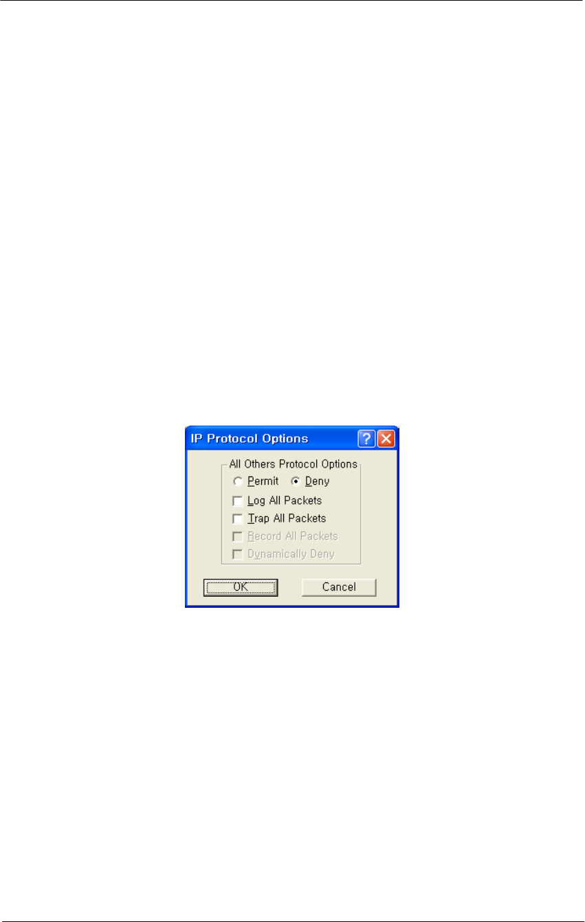
158
WLAN Cable Access Point 6220 NTPM99CA Rel 1.0 Issue 2 Nov 2004
Custom IP Protocol-- If you wish to explicitly allow or deny access to a
given IP protocol not listed in the two panels above, you can add that
protocol to the list by simply typing it in the Custom IP Protocol field
and clicking on the right arrow button [->] next to the text field. You do
not need to add a protocol to the list unless you have specific
requirements for that particular protocol.
IP Protocol Options
Clicking the Protocol Options button displays the IP Protocol Options
screen, which allows you to define an action to take when data using that
protocol is sent or received. When you select a protocol to filter, you
will need to define an action to take when data using that protocol is sent
or received. Initially, you will need to indicate whether you wish to
permit or deny that protocol. In addition, you can optionally choose to
log, trap, or record all packets, and to dynamically deny all other
protocols.
Figure 4-71
IP Protocol Option Setup window
Permit All Other Protocols Button-- Select this button if you wish to
permit all other protocols.
Deny All Other Protocols Button-- Select this button if you wish to
deny all other protocols.
Log All Packets-- Select this checkbox if you wish to log all packets.
Trap All Packets-- Select this checkbox if you wish to trap all packets.
Record All Packets-- Select this checkbox if you wish to record all
packets.
Dynamically Deny All Other Protocols-- Select this checkbox if you
wish to dynamically deny all other protocols.
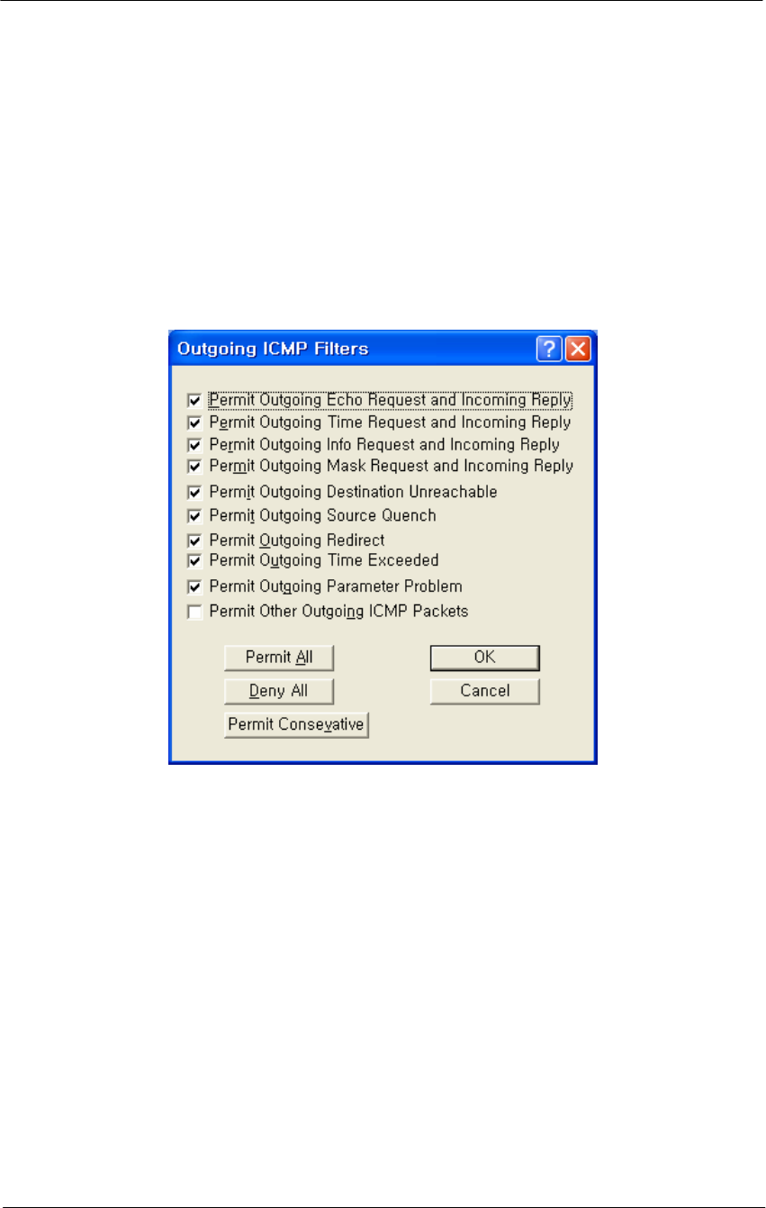
159
WLAN Cable Access Point 6220 NTPM99CA Rel 1.0 Issue 2 Nov 2004
Outgoing ICMP Filters
Clicking on the Outgoing ICMP button on the Firewall Setup screen
displays the Outgoing ICMP Filters screen, which allows you to permit
or deny ICMP packets from going out from the local to remote interfaces.
This allows you to deny diagnostic messages requested by internal
(private) sources in this filter from being sent to external (un-trusted)
machines.
Figure 4-72
Outgoing ICMP Filter Setup window
Permit Outgoing Echo Request and Incoming Reply-- Permit Echo
(ping) Requests sent from local stations to remote stations, and the
remote stations' replies.
Permit Outgoing Time Request and Incoming Reply-- Permit local
stations' Time Requests sent to remote stations and the replies from
remote machines.
Permit Outgoing Info Request and Incoming Reply-- Permit local
stations' Information Request packets sent to remote stations, and the
remote stations' replies.
Permit Outgoing Mask Request and Incoming Reply-- Permit local
stations' Mask Request packets sent to remote stations, and the remote
stations' replies.

160
WLAN Cable Access Point 6220 NTPM99CA Rel 1.0 Issue 2 Nov 2004
Permit Outgoing Destination Unreachable-- Permit Destination
Unreachable packets generated on the (private) local network to be sent
to external machines
Permit Outgoing Source Quench-- Permit Source Quench messages
generated by gateways on the local network to be sent to remote
machines sending packets to that gateway.
Permit Outgoing Redirect-- Permit Redirect messages generated by
gateways on the local network to be sent to remote machines sending
packets to that gateway.
Permit Outgoing Time Exceeded-- Permit Time Exceeded messages
generated by gateways on the local network to be sent to remote
machines sending packets to that gateway.
Permit Outgoing Parameter Problem-- Permit the local network to
send Parameter Problem messages to the remote network when there was
a problem with the header parameters of a packet.
Permit Other Outgoing ICMP Packets-- Permit other ICMP packets
not listed above to be sent from the local network to the remote network.
Permit All Button-- Clicking this button selects all checkboxes on the
Outgoing ICMP Filters screen.
Deny All Button-- Clicking this button de-selects (un-checks) all
checkboxes on the Outgoing ICMP Filters screen.
Permit Conservative Button-- Clicking this button automatically
selects all checkboxes on the Outgoing ICMP Filters screen except for
the Permit Other Outgoing ICMP Packets checkbox.
Incoming ICMP Filters
Clicking on the Incoming ICMP button on the Firewall Setup screen
displays the Incoming ICMP Filter screen, which allows you to permit or
deny ICMP packets from coming in from 'remote' to 'local' interfaces.
This allows you to deny diagnostic messages requested from external
(untrusted) sources in this filter from being sent to your local (private)
machines.
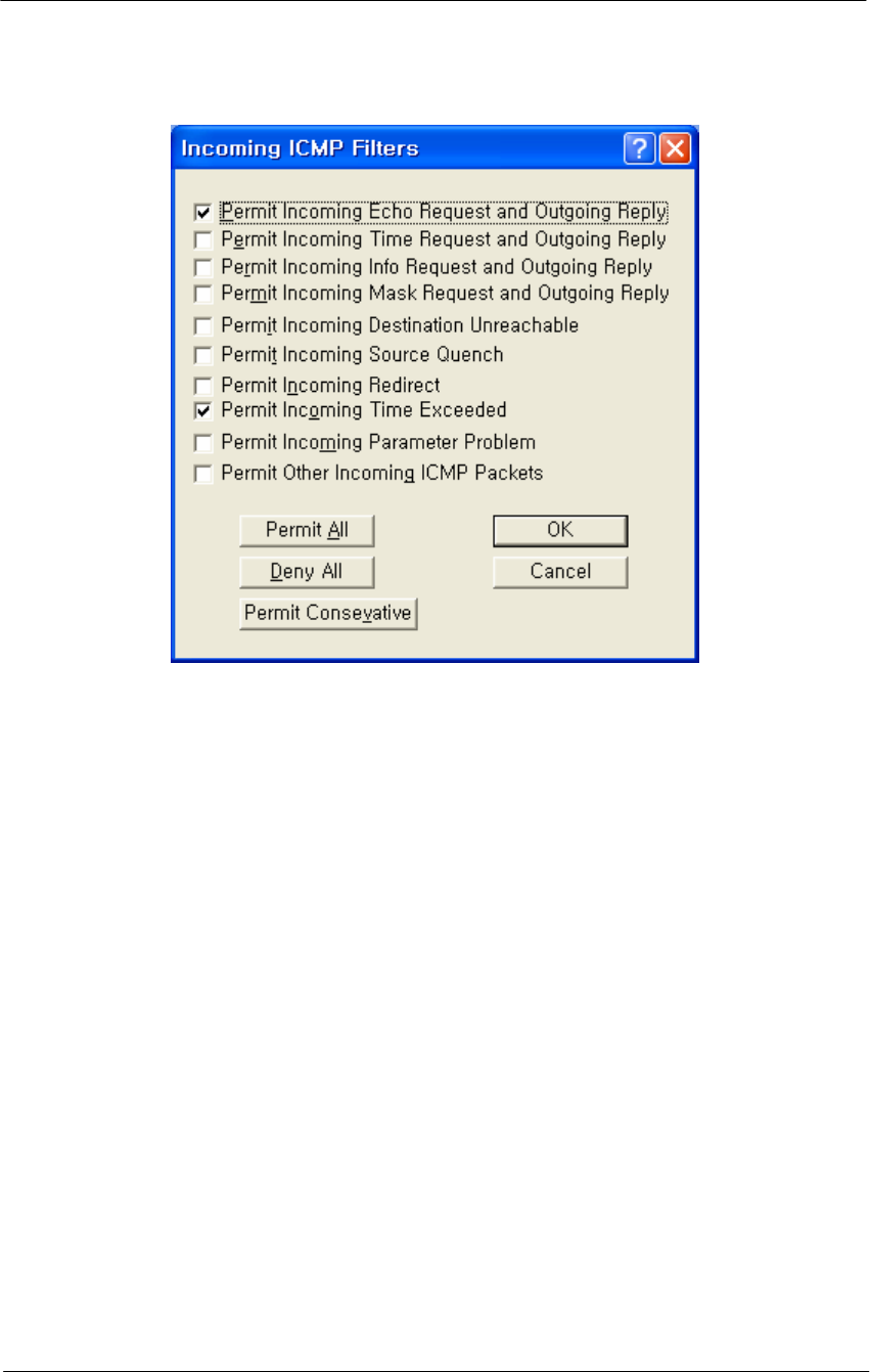
161
WLAN Cable Access Point 6220 NTPM99CA Rel 1.0 Issue 2 Nov 2004
Figure 4-73
Incoming ICMP Filter Setup window
Permit Incoming Echo Request and Outgoing Reply-- Permit Echo
Requests sent from remote (un-trusted) computers to be sent to machines
on the local (private) network, and allow the local machine to reply to
them.
Permit Incoming Time Request and Outgoing Reply-- Permit
Timestamp Requests sent from remote (un-trusted) computers to be sent
to machines on the local (private) network, and allow the local machine
to reply to them.
Permit Incoming Info Request and Outgoing Reply-- Permit
Information Request packets sent from remote (un-trusted) computers to
be sent to machines on the local (private) network, and allow the local
machine to reply to them.
Permit Incoming Mask Request and Outgoing Reply-- Permit Mask
Request packets sent from remote (un-trusted) computers to be sent to
machines on the local (private) network, and allow the local machine to
reply to them.
Permit Incoming Destination Unreachable-- Permit Destination
Unreachable messages generated by remote computers to be sent to
machines on the local network.

162
WLAN Cable Access Point 6220 NTPM99CA Rel 1.0 Issue 2 Nov 2004
Permit Incoming Source Quench-- Permit Source Quench packets
generated by gateways on the remote network to be sent to gateways on
the local network.
Permit Incoming Redirect-- Permit ICMP Redirect packets generated
by gateways on the remote network to be sent to machines on the local
network.
Permit Incoming Time Exceeded-- Permit Time Exceeded messages
generated by machines on the remote network to be sent to machines on
the local network.
Permit Incoming Parameter Problem-- Permit Parameter Problem
messages generated by machines on the remote network to be sent to
machines on the local network.
Permit Other Incoming ICMP Packets-- Permit other ICMP packets
not listed above to be sent from the (un-trusted) remote network to the
(private) local network.
Permit All Button-- Clicking this button automatically selects all
checkboxes on the Incoming ICMP Filters screen.
Deny All Button-- Clicking this button automatically de-selects (un-
checks) all checkboxes on the Incoming ICMP Filters screen.
Permit Conservative Button-- Clicking this button automatically
selects the following checkboxes on the Incoming ICMP Filters screen:
Permit Incoming Echo Request and Outgoing Reply
Permit Incoming Destination Unreachable
All other checkboxes are automatically de-selected (unchecked).
Add Authentication Record
The Add Authentication Record screen is used to add an SNMP-based
username/password firewall authentication bypass class. The
Authentication class works much like a UNIX user group does; you can
specify what types of packets a person in this authentication class can
pass through the firewall when logged in with the approved username
and password.
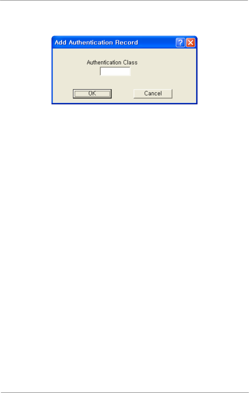
163
WLAN Cable Access Point 6220 NTPM99CA Rel 1.0 Issue 2 Nov 2004
Figure 4-74
SNMP Authentication Record Setup window
Authentication Class Number-- Enter a number for an SNMP-based
username/password firewall authentication bypass class. The
Authentication class works much like a UNIX user group does; you can
specify what types of packets a person in this authentication class can
pass through the firewall when logged in with the approved username
and password.

165
Administration
The WLAN Cable Access Point 6220 (APU, CSU) has the following
management and operational features listed below:
Save Configuration
Load new Configuration
Load new License
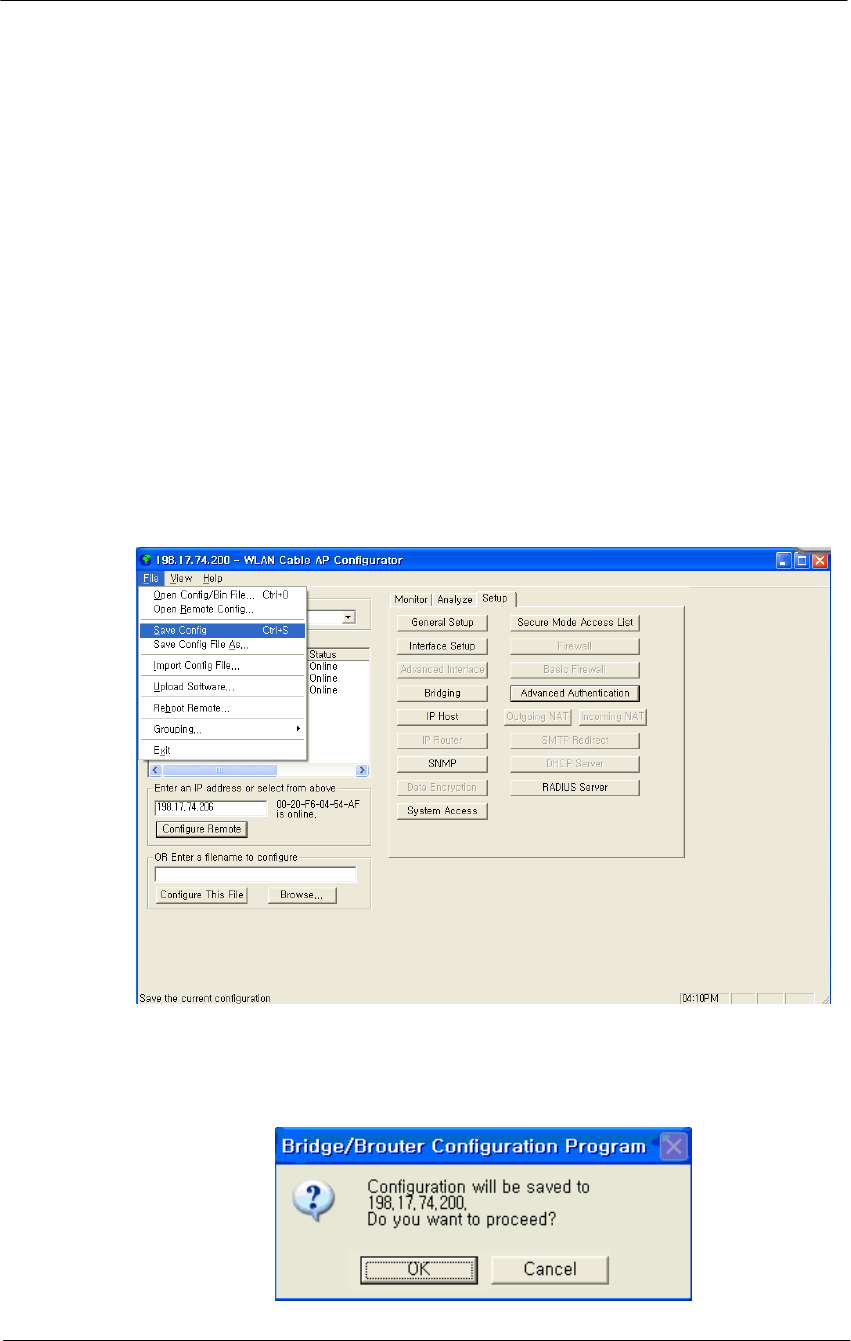
166
WLAN Cable Access Point 6220 NTPM99CA Rel 1.0 Issue 2 Nov 2004
Save configuration
Saving the current configuration settings to the hardware device is a one-
step process:
Use this File Menu option to save the base station configuration
parameters to the location from which they were read. If the
configuration was read from a base station, it will be saved to the APU
and CSU from which it was read. If the configuration was read from a
file, the modified configuration will be saved back to that file.
To import a saved configuration to an APU or CSU, first connect to the
base station using Open Remote Config, then use Import Config File.
1. From the File Menu, select Save Config.
Figure 5-1
Save Config Menu
2. Click on the ‘Yes’ button
Figure 5-2
Confirm Save Config Window
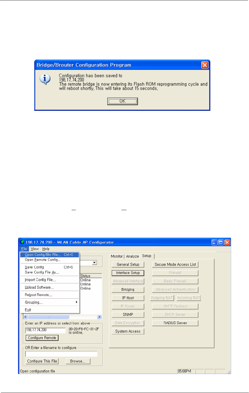
167
WLAN Cable Access Point 6220 NTPM99CA Rel 1.0 Issue 2 Nov 2004
3. The message box will be displayed, as shown below, and then left click on
the OK button.
Figure 5-3
Reboot Message Dialog Box
4. Just after this saving, APU or CSU will be restarting automatically.
Load new configuration
The 'import config file' option enables you to 'copy' the parameter values
that you entered to configure the first Secure Data Mode Station to the other
units. The “import config file” option enables you to 'copy' the parameter
values that you entered to configure the first Secure Data Mode Station to
the other units.
1. From the File menu, select Open/Config Bin File.
Figure 5-4
Open Config/Bin File Menu
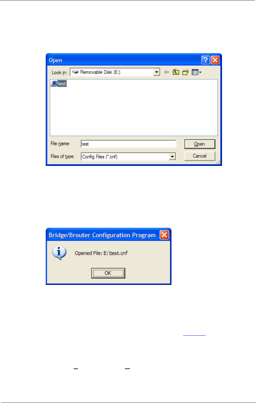
168
WLAN Cable Access Point 6220 NTPM99CA Rel 1.0 Issue 2 Nov 2004
2. And the browse window will appear.
Figure 5-5
Open Config File Window
3. Select the configuration file in the specific folder, and Click ‘Open’
button,
4. Then, bridge/brouter Configuration Program” screen will appear.
Figure 5-6
Confirm Open Config File Dialog Box
5. Left click on the OK button.
Load new license
There are ten steps that must be done to import the .bin file and its
corresponding license file. Be sure you have downloaded and know the
location of your files before you start.
1. From the File menu, select Upload Software, and the browse window
will appear.
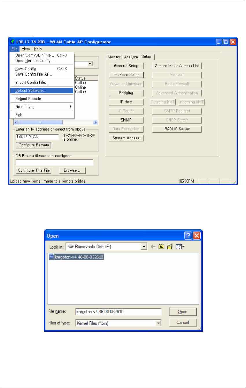
169
WLAN Cable Access Point 6220 NTPM99CA Rel 1.0 Issue 2 Nov 2004
Figure 5-7
Upload Software Menu
2. Browse to the location of your .bin file, and select it.
Figure 5-8
Open binary Window
3. Click on the ‘Open’ button, and the "License Key Setup" screen will
appear:
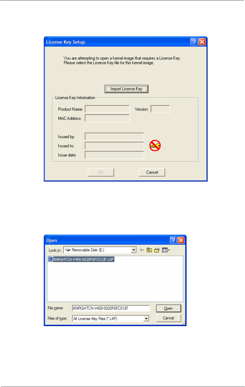
170
WLAN Cable Access Point 6220 NTPM99CA Rel 1.0 Issue 2 Nov 2004
Figure 5-9
License Key Setup Window
4. Click on the "Import License Key" button, and an "Open" dialog box
will appear:
Figure 5-10
Open License Key Window
5. Select the license file that corresponds to the Ethernet MAC of the unit
you are working with. (If you have "Licenses for this MAC address"
selected in the file type drop box, only the licenses for the MAC of the
current unit will appear.)
6. Click on the ‘Open’ button
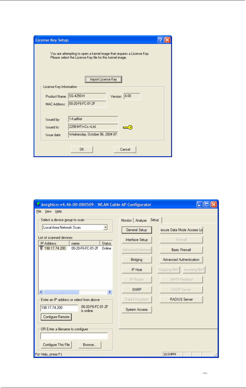
171
WLAN Cable Access Point 6220 NTPM99CA Rel 1.0 Issue 2 Nov 2004
Figure 5-11
License key setup window
7. Click on the ‘OK’ button
Figure 5-12
Setup window
8. You can see an initial setup windows and then, From the File menu,
select upload software as below.
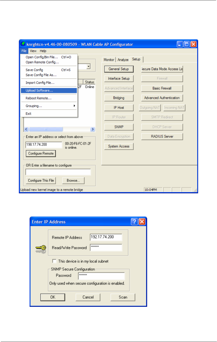
172
WLAN Cable Access Point 6220 NTPM99CA Rel 1.0 Issue 2 Nov 2004
Figure 5-13
Selecting Upload Software
Figure 5-14
Enter IP address dialog
9. Enter the IP address of the unit to upload new software binary and Click
on the ‘OK’ button.
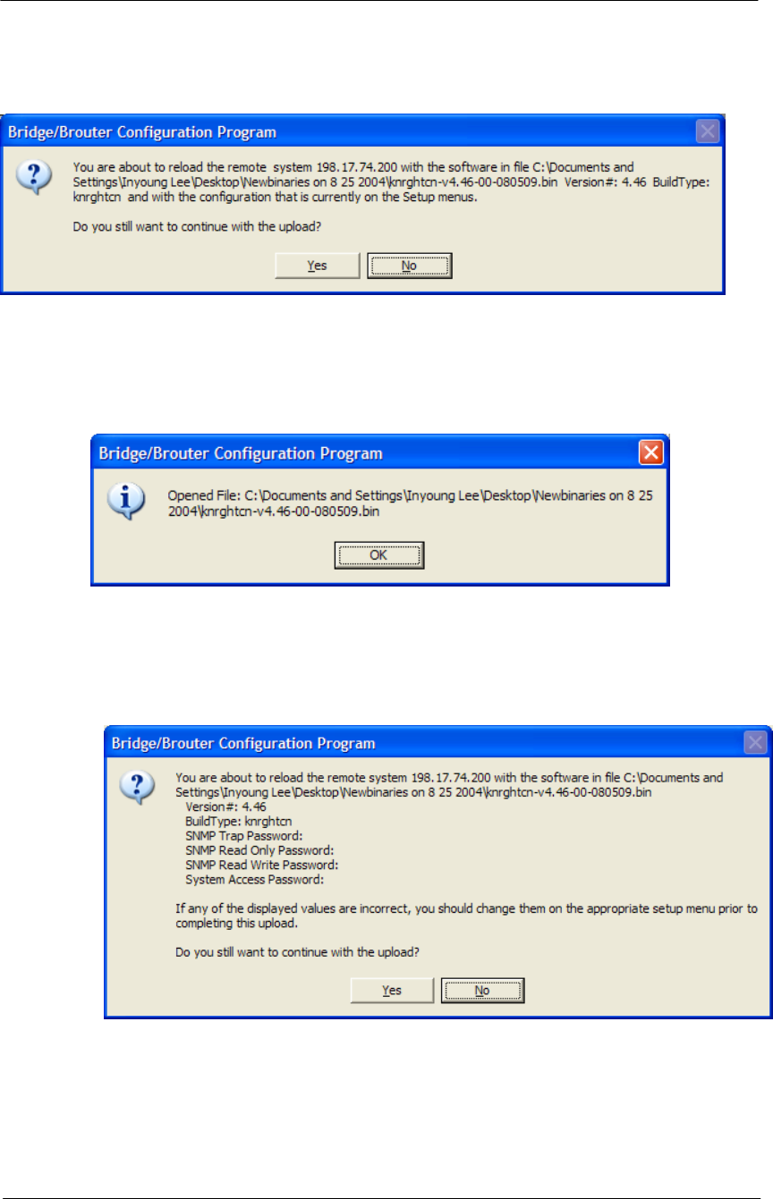
173
WLAN Cable Access Point 6220 NTPM99CA Rel 1.0 Issue 2 Nov 2004
Figure 5-15
Uploading Confirmation Dialog 1
10. Click on the ‘OK’ button
Figure 5-16
Uploading Confirmation Dialog 2
11. Click on the ‘OK’ button
Figure 5-17
Uploading Binary Information Dialog Box
12. Click on the ‘OK’ button
13. “Saving ….Please be patient” screen will appear as below
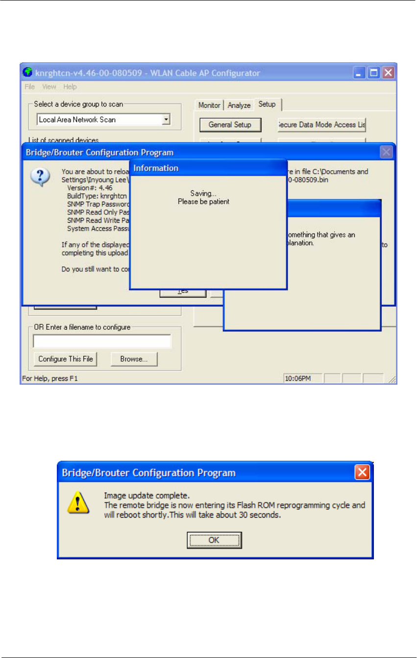
174
WLAN Cable Access Point 6220 NTPM99CA Rel 1.0 Issue 2 Nov 2004
Figure 5-18
Saving software uploading window
14. Click on the ‘OK’ button
Figure 5-19
Reboot Message Dialog Box
15. Click on the ‘OK’ button
16. Software Uploading complete.

175
Troubleshooting

176
WLAN Cable Access Point 6220 NTPM99CA Rel 1.0 Issue 2 Nov 2004
1. APU Power cannot be Turned ON.
Check that the CATV Power (45VAC ~ 95VAC) is supplied thorough the
coaxial line by measuring the AC Voltage Level.
If no power signal is detected at the end of the coaxial cable, you should search a
problem point on the CATV Network while moving up toward the ONU and
UPS Power supply.
2. LED 2(Link 1) is continuously blinking after running a long time and all
network entity including APU cannot receive IP address from DHCP
server.
Measure the RF signal level at the end of the coaxial cable or monitoring port in
the APU enclosure. Also check whether or not the RF signal level is beside the
range of required signal. If so, adjust the power level by tuning all related
network facility to meet the requirements for the operation of the Cable Modem.
* Normal Power level (DOCSIS): +15 to -15 dBmV
3. LED 3(Link 2)/LED 4(Radio Link) are turned off.
In the AP Configurator, select and click the setup tap, move to “interface” to see
whether or not Ethernet 2 and 802.11 is enabled. If disabled, check each
interface. If the LED lights are still turned off in spite of this work, the APU
system may have failed. If so, contact the Nortel local representative or technical
support center.
4. How do I see and configure a setup parameter of the CSU without a radio
connection to the APU?
The only devices that will display in the Configurator local scan window are the
units in the same subnet as your management computer. If the device in question
is not displayed in your local scan window, change the IP address (Client PC) to
any one of the subnet IP address groups “198.17.74.XXX” and then, you can
find out the CSU entity with the IP address “198.17.74.254”.
5. Why can CSU setup a radio connection to the APU?
Such situations are caused by various reasons as below:
- Mismatching between the radio setup parameter of APU and that of CSU
+ Radio Channel
+ Network ID (NWID)
+ WEP Encryption Key
- Radio Link Designing Problem(Link Distance, Antenna Direction and so
on)

177
WLAN Cable Access Point 6220 NTPM99CA Rel 1.0 Issue 2 Nov 2004
6. How many CSU subscribers can connect to a single WLAN Cable Access
Point (APU Secure Data mode)?
Eight CSU subscribers can connect to a single WLAN Cable Access Point in
secure data mode.
7. How does the number of CSU Secure Data modes affect wireless
throughput?
As more CSU Secure Data modes are added, the APU Secure Data mode Base
Station mode is still able to effectively manage the throughput of the overall
wireless link. Just as on any shared medium, each station's throughput is
determined by the overall usage of the wireless link. The more stations
transmitting on the link at a time, the lower each individual station's throughput
goes. However, Secure Data mode performs in such a way that up to a point, the
more heavily loaded the network becomes, the higher the overall throughput
becomes.
For example, due to the intricacies of our Adaptive Dynamic Polling algorithms
and Secure Data mode 'fairness' principles, a single-user FTP session does not
use all of the possible wireless bandwidth. But when performing several
different transfers to and from different CSU Secure Data modes, the actual
overall bandwidth of the Secure Data mode network increases. In general, the
heavier a Secure Data mode network is loaded, the higher the total bandwidth
used becomes.
8. How do I check throughput?
Network throughput can be tested and analyzed using the Ping Fill test. This test
dynamically fills the network connection with ICMP Echo (ping) packets and
waits for the responses from the target station. Since each packet sent is echoed
back to the sender, this tests the overall wireless throughput in both directions.
Choosing the correct parameters is crucial to obtaining accurate Ping Fill test
results. The speed at which the target station responds to the ICMP Echo packets
is crucial to correctly assess the speed of the wireless link.
The IP stacks in some PC operating systems, such as Microsoft Windows, often
do not respond quickly enough to the ICMP Echo packets to obtain an accurate
assessment of your network throughput. When running the Ping Fill test to a
Microsoft Windows system, your results may be slightly lower than normal
throughput.
9. How do I read the configuration from a device if I cannot see the unit in the
local scan window?
The only devices that will display in the Configurator local scan window are the
units in the same subnet as your management computer. For example your PC
has an IP address 64.22.33.13 with a subnet mask of 255.255.255.0 and your

178
WLAN Cable Access Point 6220 NTPM99CA Rel 1.0 Issue 2 Nov 2004
device has an IP address of 65.23.11.2 with a subnet mask of 255.255.0.0. The
device in question would not display in your local scan window.
Even though you may be able to ping the unit it may not be visible in the local
scan window. In the Configurator, select the file menu, and then open remote
config and then type in the IP and the password. It may be necessary to select
the "this device is in my local subnet" check box to actually read the
configuration from the unit. Attempt to read the configuration with it un-checked
first. If the configuration cannot be read try with this box checked.
10. I seem to have lost or forgotten the read/write password to manage my
product.
How can I get back in to manage the unit?
If the read/write password has been lost or forgotten, there is only one thing that
can be done about this in order to be able to manage the unit again. The unit
must be put into force reload mode and the firmware must be reloaded. All
configuration settings will be lost. Physical access to the unit is required in order
to accomplish this procedure.
11. I am performing a wireless link test from a CSU Secure Data mode and one
of my CSU Secure Data modes on the other side of my base station is
showing up, is this a problem?
It is a normal function to be able to see the other units in the wireless link test
this way. This shows you what devices are within range so that the radio can
"hear”. As long as the units are set as Secure Data mode CSU Secure Data
modes, there is no way they will actually be communicating with each other.
They are receiving radio signals from each other that they have to interpret and
dump. This is not an optimal solution and should be changed when it is practical
to do so by isolating antennas, changing polarity or reducing output power if
possible.
12. Please provide the list of parameters for the different levels of signal
strengths i.e. No Connection, Poor, Acceptable, Good, and Excellent. How
do I determine what is good and bad?
What these values will mean, is somewhat specific to the environment being
worked under. For example, a Signal to Noise Ratio of 15 may be fine for one
area and 15 may not work very well in a high noise area. So here are some
general guidelines. Keep in mind all the information below is related to Secure
Data mode, for 802.11b mode replaces retransmit with dropped packets:
There are some further items to note:
Link planning should be done in your general geographic area and your links
should be set up with an extra margin that your company determines.
Links are best performed when possible with high gain antennas as opposed to

179
WLAN Cable Access Point 6220 NTPM99CA Rel 1.0 Issue 2 Nov 2004
low gain amplified antennas
Noise is typically introduced by failing amplifiers and problems with connectors
and defective radios. Signal typically drops with bad cabling, connectors or
antenna misalignment, radio power issues Network ID and Channel values being
the same, may help stability in marginal links.
Marginal (sporadic links) typically occur in SNR ranges from 5-9, 10-15 usually
will keep association with retransmits or some packet loss. SNR from 16 and up
usually are acceptable for every day operation.
If SNR is over 25 and throughput is poor, overdriving or multi-path may be the
cause of the problems.
Secure Data Mode Station Entries - Provides information on octal packet,
retransmitted packets and failed packets. A value other than 0 under failed
packets typically points to a link issue. Keep in mind TC retransmits a packet 9
times, (with the initial packet 10 total).
This has occurred and the packet has been dropped when a failure occurs.
Retransmits should be 15% or less of total transmits, this may indicate signal,
noise or antenna alignment issues.
Remote Statistics - Check each Ethernet Interface, any errors or collisions may
be signs of link speed or greater network related issues.
Check each wireless interface. Specifically, compare the Frame Check Sequence
errors to the bytes in values. Typically FCS occurs on any wireless connection.
This should only be a concern if the value exceeds approximately 10% of the
bytes in value. This may be an indicator of signal/multi-path issues.
13. Can I block unwanted MAC addresses from the Ethernet interface?
It is possible to set an Access Control List to set all of your allowable MAC's on
the Ethernet (everything else on the Ethernet will be denied) by reading the
configuration from the unit with the WLAN Cable AP Configurator. Go to the
Setup tab -- General Setup -- Select the Mac Authentication Access control radio
button and click OK. Then select the Setup tab -- Advanced Authentication --
check the Access Control List and then click the Setup button. Add all your
allowable MAC's and select the Ethernet interface to apply the ACL.

181
Appendix
A. Specification
B. DOCSIS Specification
C. Antenna Type
D. Enclosure Dimension
E. Site Survey
F. Wireless Network Planning
G. SNMP MIB List & Example Values

182
WLAN Cable Access Point 6220 NTPM99CA Rel 1.0 Issue 2 Nov 2004
Appendix A. Specification
Access Point Unit(APU)
General
o Case: Aluminum alloy steel (Waterproof, EMI protection, Vibration Robust)
o Size: 300 (W) x 232.6 (L) x 112 (D) (mm)
11.81 (W) x 9.157 (L) x 4.40 (D) (inch)
o Weight(without antenna): 3.14 Kg / 6.9234 lbs
o Elements: Access Point, Cable Modem, HFC Signal Filter, Power Supply Unit
o Ports: Coaxial Cable Port, Monitoring Port, Antenna Port (N-type)
o LED Panel: Power, Cable Modem Link, LAN, WLAN, CM-AP Link
o Temperature: -40 ~ 65 ºC (Operating)
o Power supply: Input Power 45 ~ 95VAC (Supplied by CATV UPS)
Output Power 3.3VDC (3A), 9VDC (1.5A)
o Power Consumption : MAX 12W (Current < 0.5A)
Hardware
Radio Card
o Operation Frequency: 2.4 ~ 2.4835GHz (ISM Band; a/b/g ready with radio
upgrade)
o Wireless LAN standard: IEEE 802.11b (a/b/g ready w/ radio upgrade)
o Frequency: 2.4GHz ISM band(North America 11 Channels)
o Modulation: Direct Sequence Spread Spectrum (DBPSK, DQPSK, CCK)
o Data rate: 1M, 2M, 5.5M, 11Mbps with auto fall-back
o Receive sensitivity: Min. -83dBm at 11Mbps
HFC Filter
o Input Signal : HFC Signal(-15dBmV ~ +15dBmV), AC Power (45VAC ~
95VAC/ Max: 135VAC)
o Output : AC Power, HFC Signal, Monitoring Signal(Attenuated by 20dB)
Power Converter (AC-DC)
o Input Voltage Range: 45 VAC ~ 135VAC
o Output Voltage/Current: +3.3Vdc(3A), +9V(1.5A)

183
WLAN Cable Access Point 6220 NTPM99CA Rel 1.0 Issue 2 Nov 2004
Software
o Firmware : APU Secure Data Mode(Base Station), Wi-Fi Access Point
o Wireless Service Protocol : Secure Data Mode, Dynamic Polling
o 802.1x - MD5, TLS, TTLS, PEAP over EAP (SDM mode)
o MAC access control – 32 local MAC Address Table (SDM mode)*
o Standard RADIUS server support
o Wired Equivalent Privacy encryption - 64, 128
o Firewall(ICMP/UDP/TCP/IP Protocol Filtering)
o Layer 2 Protocol Filtering
o BOOTP/DHCP(Server, Relay, Client), Static IP
o NAT(Incoming/Outgoing)
o Routing Protocol(RIP v2, Static)
o Restriction of Broadcast Storm
o SNMP v1, Software upgrade via TFTP
o GUI Program : Windows Based
o Throughput Analysis: Ping Fill
o Radio Performance Testing Tool: Antenna Alignment
o Remote Statistics Monitoring
o SNMP Traps
o MIB II
(*) There is a limit of 32 if you use MAC address and comment per entry. However
each APU can support 64 CSU's associating with it in SDM mode if you use only
MAC address per entry. If you use a RADIUS server for this setup, there is no
limitation.
Cable Modem Specification (Hardware / Software)
o Standard : DOCSIS 2.0 compliant
o Frequency : 5~42MHz (Upstream), 88~860MHz (Downstream)
o Modulation : QPSK/16QAM/64QAM/128QAM(Upstream),
64QAM/256QAM (Downstream)
o Data Rate: 5.12Mbps/QPSK, 30.34Mbps / 64QAM (Upstream)
30.34Mbps/64QAM, 42.88Mbps / 256QAM (Downstream)
o Channel Bandwidth
Upstream: 200 KHz, 400 KHz, and 800 KHz, 1.6 MHz, 3.2 MHz, 6.4 MHz
Downstream: 6MHz
o Error correction : Reed-Solomon (Upstream), Reed-Solomon
Trellis(Downstream)
o Signal Level : + 8dBmV ~ + 53dBmV(All Modulation),
-15dBmV ~ + 15dBmV
o Input Impedance: 75 Ohm

184
WLAN Cable Access Point 6220 NTPM99CA Rel 1.0 Issue 2 Nov 2004
o Interface: RJ 45 Ethernet port, USB 1.1 port
o SNMP v1, Software upgrade via TFTP

185
WLAN Cable Access Point 6220 NTPM99CA Rel 1.0 Issue 2 Nov 2004
Corporate service unit (CSU)
General
o Case: Aluminum alloy steel (Body), RADOME
o Size: 180 (W) x 239 (L) x 81 (D) (mm)
7.08 (W) x 9.40 (L) x 3.19 (D) (inch)
o Weight: 1.3 Kg / 2.8659 lbs
o Elements: Access Point, POE Splitter, Built-in Antenna in CSU body,
RADOME
o Ports: POE Ethernet Port(RJ-45/CAT5), 12V DC Jackk
o Temperature: -40 ~ 65 ºC (Operating)
o Power supply(Option): 802.3af compliant POE Injector(45V DC, 315 mA)
o Power Consumption : MAX 10W (Current < 0.4A)
Hardware
Radio Card
o Operation Frequency: 2.4 ~ 2.4835GHz (ISM Band; a/b/g ready with radio
upgrade)
o Wireless LAN standard: IEEE 802.11b (a/b/g ready w/ radio upgrade)
o Frequency: 2.4GHz ISM band(North America 11 Channels)
o Modulation: Direct Sequence Spread Spectrum (DBPSK, DQPSK, CCK)
o Data rate: 1M, 2M, 5.5M, 11Mbps with auto fall-back
o Receive sensitivity: Min. -83dBm at 11Mbps
POE Splitter
o IEEE 802.3af Compatible
o Input Signal : DC Power (48V DC, Max 315mA), Base-band Signal(Ethernet)
o Output : DC Power(3.3V DC), Base-band Signal(Ethernet)
POE Injector
o IEEE 802.3af Compatible
o Input Signal : AC Power (90~264V), Base-band Signal(Ethernet)
o Output : POE Signal(DC Power(48V), Base-band Signal(Ethernet))
Software
o Firmware : CSU Secure Data Mode(Subscriber Station), Wi-Fi Access Point
o Wireless Service Protocol : Secure Data Mode, Dynamic Polling
o Standard RADIUS server support
o Wired Equivalent Privacy encryption - 64, 128
o Firewall(ICMP/UDP/TCP/IP Protocol Filtering)
o Layer 2 Protocol Filtering

186
WLAN Cable Access Point 6220 NTPM99CA Rel 1.0 Issue 2 Nov 2004
o BOOTP/DHCP(Server, Relay, Client), Static IP
o NAT(Incoming/Outgoing)
o Routing Protocol(RIP v2, Static)
o Restriction of Broadcast Storm
o SNMP v1, Software upgrade via TFTP
o GUI Program : Windows Based
o Throughput Analysis: Ping Fill
o Radio Performance Testing Tool: Antenna Alignment
o Remote Statistics Monitoring
o SNMP Traps
o MIB II
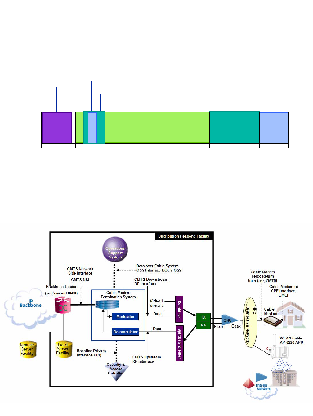
187
WLAN Cable Access Point 6220 NTPM99CA Rel 1.0 Issue 2 Nov 2004
Appendix B. DOCSIS Specification
Figure A.1
CATV Frequency Range
CATV: UPSTREAM 5-42(30) MHz, DOWNSTREAM 50-750(550) MHz
DATA: UPSTREAM 5-65MHz, DOWNSTREAM 88-750(550) MHz
Figure A.2
DOCSIS Reference System Diagram
Upstream (DOCSIS)
54 MHz 750 MHz
5.75~41.75 MHz 552 MHz 864 MHz
CATV Channel
Data
Service
Downstream (DOCSIS)
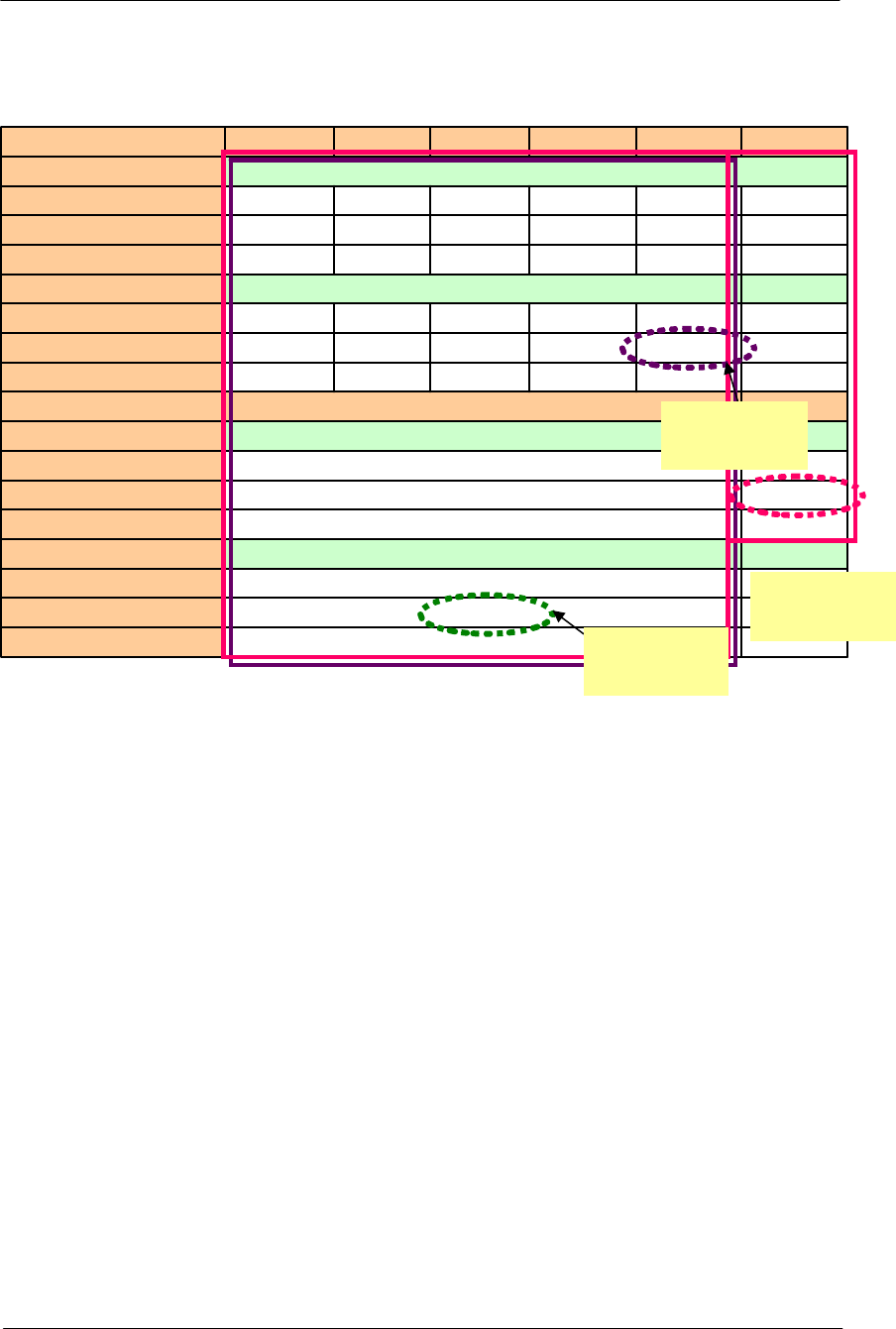
188
WLAN Cable Access Point 6220 NTPM99CA Rel 1.0 Issue 2 Nov 2004
Table A.1
DOCSIS RF Specification Table
27.6Mbps
30.72Mbps
10.24Mbps
18.4Mbps
20.48Mbps
5.12Msps
9.2Mbps
10.24Mbps
5.12Msps
6.4MHz
37Mbps Effective Data Rate
42.9Mbps Total Data Rate
5.360Mbps SYMBOL Rate
256QAM Modulation TYPE
27Mbps Effective Data Rate
30.34Mbps Total Data Rate
5.057Msps SYMBOL Rate
64QAM Modulation TYPE
6MHz RF BW
9.2Mbps 4.5Mbps 2.3Mbps 1.2Mbps 0.6Mbps Effective Data Rate
10.24Mbps 5.12Mbps 2.56Mbps 1.28Mbps 0.64Mbps Total Data Rate
2.56Msps 1.28Msps 0.64Msps 0.32Msps 0.16Msps SYMBOL Rate
16QAM Modulation TYPE
4.6Mbps 2.3Mbps 1.2Mbps 0.6Mbps 0.3Mbps Effective Data Rate
5.12Mbps 2.56Mbps 1.28Mbps 0.64Mbps 0.32Mbps Total Data Rate
2.56Msps 1.28Msps 0.64Msps 0.32Msps 0.16Msps SYMBOL Rate
QPSK Modulation TYPE
3.2MHz 1.6MHz 800 KHz 400 KHz 200 KHz RF BW
DOCSIS 2.0
Upstream
Maximum
DOCSIS 1.1
Upstream
Maximum
DOCSIS
1.1&2.0
Down stream

189
WLAN Cable Access Point 6220 NTPM99CA Rel 1.0 Issue 2 Nov 2004
Appendix C. Antenna Type
NTA.2407 Panel Antenna
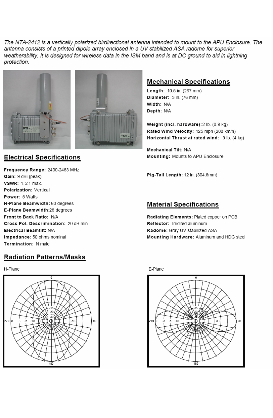
190
WLAN Cable Access Point 6220 NTPM99CA Rel 1.0 Issue 2 Nov 2004
NTA.2412 Bidirectional Antenna
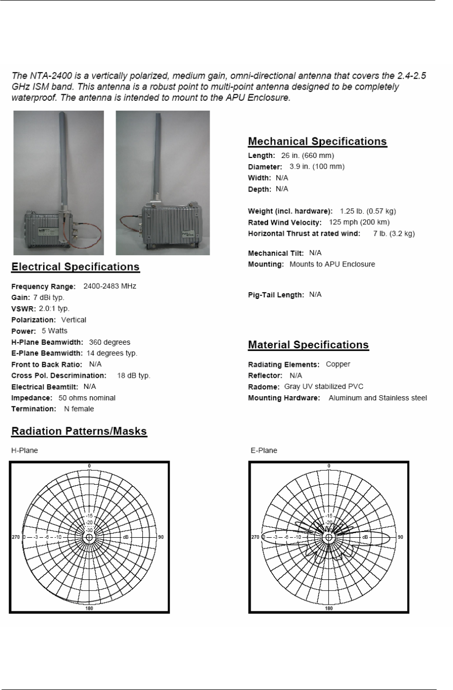
191
WLAN Cable Access Point 6220 NTPM99CA Rel 1.0 Issue 2 Nov 2004
NTA.2400 Omni directional Antenna
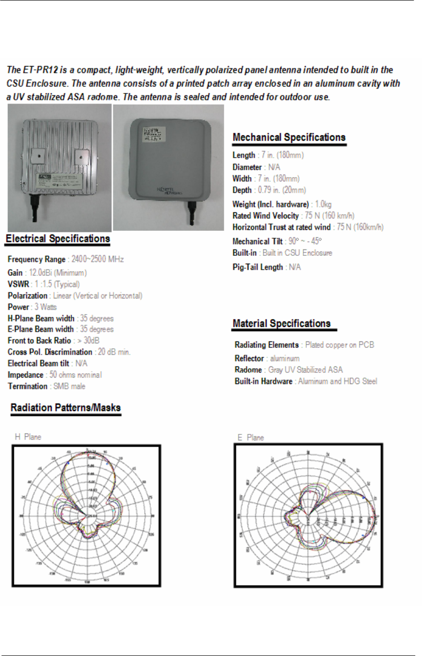
192
WLAN Cable Access Point 6220 NTPM99CA Rel 1.0 Issue 2 Nov 2004
ET-PR12 Built-in Panel Antenna
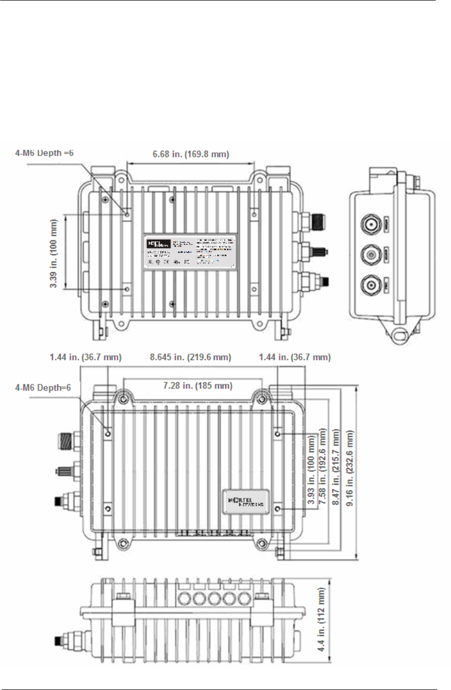
193
WLAN Cable Access Point 6220 NTPM99CA Rel 1.0 Issue 2 Nov 2004
Appendix D. Enclosure Dimension
Access Point Unit(APU)
Figure A.3
APU Dimension
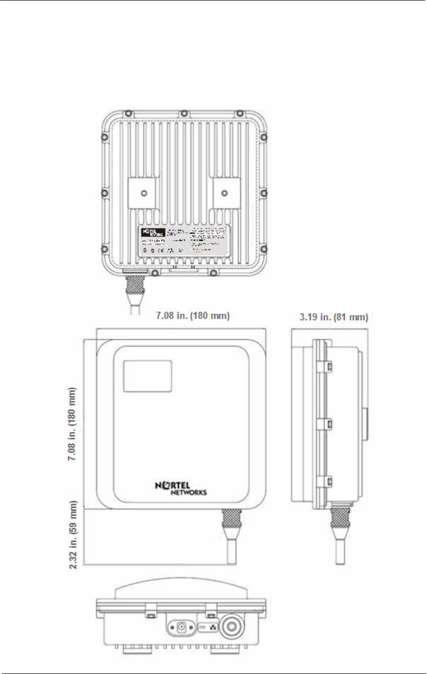
194
WLAN Cable Access Point 6220 NTPM99CA Rel 1.0 Issue 2 Nov 2004
Corporate service unit(CSU)
Figure A.4
CSU Dimension

195
WLAN Cable Access Point 6220 NTPM99CA Rel 1.0 Issue 2 Nov 2004
Appendix E. Site Survey
Calculating the system parameters
Free Space
Microwave signal will be attenuated as it travels through space according
to the following equation
Gs = Ptx + Gtx + Grx – (RS)
Gs : System Gain
Ptx : Transmit power level in dBm
Gtx : Transmit antenna gain in dBi
FSL: Free space loss attenuation in dB
Grx : Receive antenna gain in dBi
RS : Receiver Sensitivity in dBm
Lt = FSL + Mp
Lt : Transmission Loss
FSL : Free Space Loss
FM : Fade Margin + Other Loss(Cable)
FSL : 92.4 + 20Log(F) + 20Log(R)
F: Frequency (MHz)
R: Range (Km)
The Radio Signal transmitted can reach the other end only when the
system gain is equal or larger than the Transmission Loss.
An installation engineer should determine the antenna gain to meet the
above condition with EIRP, the summation of the antenna gain and the
output power not exceeding FCC Radio Regulations.
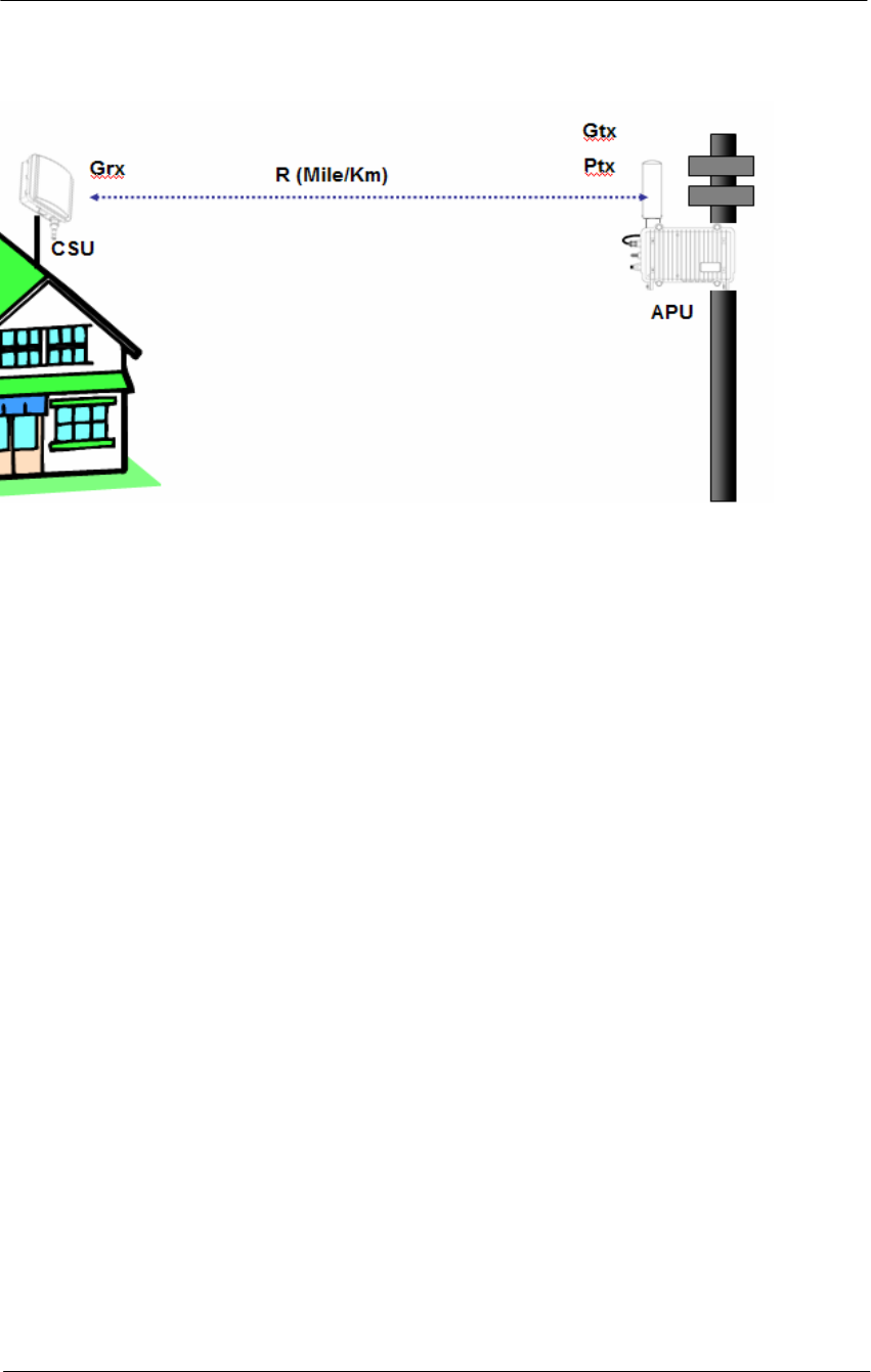
196
WLAN Cable Access Point 6220 NTPM99CA Rel 1.0 Issue 2 Nov 2004
Figure A.5
Radio Link Analysis
Determining the Distance between both sites
Gs = Lt = Ptx + Gtx + Grx –(RS) = (92.4 + 20Log(F) + 20Log(R))+10
Gs = Constant = (36.6 + 20Log(F) + 20Log(R))+10
Calculating Distance (R) between both sites
Case Study
Transmitter: APU, Receiver: CSU
Ptx : 15dBm
Gtx : 7dBi(Omni-directional)
Grx : 18dBi
RS : - 83dBm
F : 2.4 GHz
R: 5 mile
FM: 12 dB (Conventional Setting Value)
Gs = Ptx + Gtx + Grx – (RS)
Gs(Flat Panel) = 15 + 15 + 18 - (-83) = 131
FSL : 36.6 + 20Log(F) + 20Log(R)
FSL = 36.6 + 20Log(2400) + 20Log(5) = 118.2 dB
Lt = FSL + FM
Lt = 118.2 + 12 = 130.2
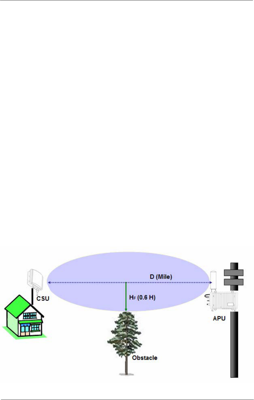
197
WLAN Cable Access Point 6220 NTPM99CA Rel 1.0 Issue 2 Nov 2004
FRESNEL ZONE
For a link to truly be line-of-sight, no objects such as buildings, cars, etc.
or the ground may be within a certain height perpendicular to the line of
sight path called the first fresnel (pronounced fray-nell) zone.
This height of the fresnel zone H (in feet) is specified by the equation
below.
H = 43.3 x sqrt (D/ (4xF))
D: distance in miles between antennas
F: Frequency in GHz
Case Study
D: 10
F: 2.4
H = 43.3 x sqrt (10/ (4x2.4))
H = 44.19 feet
HF = 44.19 * 0.6 = 26.5 feet
If 60 percent of the FRESNEL ZONE is free from obstructions the link
will generally behave as LOS (Line of sight).
Figure A.6
FRESNEL ZONE
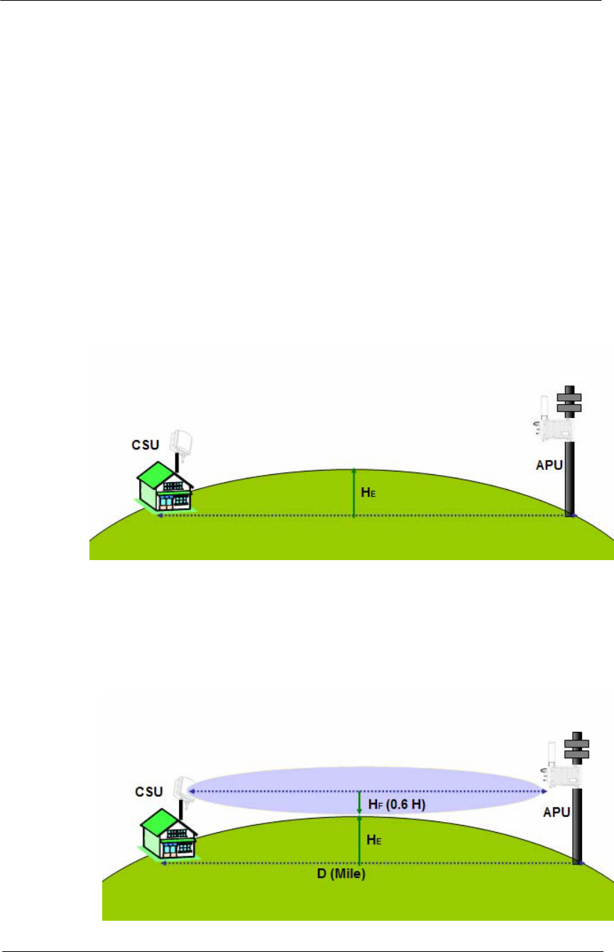
198
WLAN Cable Access Point 6220 NTPM99CA Rel 1.0 Issue 2 Nov 2004
Earth bulge
For long links the curvature of the earth will may block the line of sight
path unless the antennas at both ends of the link are positioned high
enough above the ground. This height must be added to the FRESNEL
ZONE height for each antenna.
HE = D^2/8
H = Earth bulge height in feet
D=distance between antennas in miles
Case Study
D: 10 mile
HE = D^2/8 = 10^2/8 = 12.5 feet
Figure A.7
Earth Bulge
Total height required at midpoint
HT = HF + HE
Figure A.8
Total height
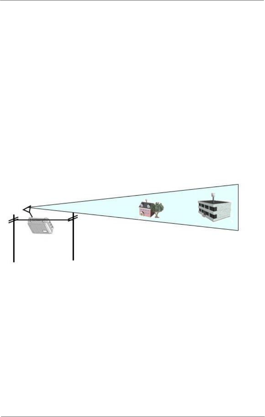
199
WLAN Cable Access Point 6220 NTPM99CA Rel 1.0 Issue 2 Nov 2004
Appendix F. Wireless Network Planning
This section provides a general concept and designing tips about typical Point to Multi-
Point (PMP) and Point to Point (PTP) network configuration.
Selecting Antenna Type
Directional Antenna (NTA 2407)
Flat panel antennas have a directional gain and are ideally suited for
short and medium range bridging. For example, two office buildings that
are across the street from one another and need to share a network
connection would be a good scenario to use flat panel (directional)
antennas.
Figure A.9
Directional Antenna concept (Flat Panel Antenna)
Omni-Directional Antenna (NTA 2412)
Omni-directional antennas are used when coverage in all directions
around the horizontal axis of the antenna is required. Omni-directional
antennas are most effective where large coverage areas are needed
around a central point, they commonly used for point-to-multipoint
designs with a star topology.
The antenna should be placed on top of a structure (such as a building) in
the middle of the coverage area. For example, in a college campus the
antenna might be placed in the centre of the campus for the greatest
coverage area.
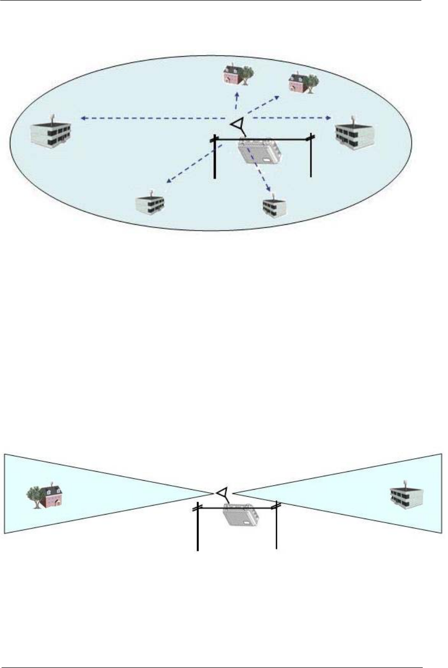
200
WLAN Cable Access Point 6220 NTPM99CA Rel 1.0 Issue 2 Nov 2004
Figure A.10
Omni-directional Antenna concept
Bi-directional Antenna (NTA 2400)
Bi-directional antennas are used when coverage is required in a selected
horizontal axis of the antenna is required. Bi-directional antennas are
most effective where a particular coverage area is needed around a
central point. For example, placing a bi-directional antenna along a street
would provide coverage on each side of the street. The antenna pattern is
similar to a Figure A.10 pattern.
Figure A.11
Bi-directional Antenna concept

201
WLAN Cable Access Point 6220 NTPM99CA Rel 1.0 Issue 2 Nov 2004
Selecting Radio Channel
Direct-Sequence Channel Layout
Most locations are deploying 802.11 products based on direct-sequence
technology because the WLAN products are based on direct-sequence
technologies. Direct Sequence underlies both the 2-Mbps DS PHY and
the 11-Mbps HR/DSSS PHY. Both standards use identical channels and
power transmission requirements.
Direct-sequence products transmit power across a 25-MHz band. Any
access points must be separated by five channels to prevent inter-access
point interference. Selecting frequencies for wireless LAN operation is
based partly on the radio spectrum allocation where the wireless LAN is
installed. See Table A.2
Table A.2
Radio channel usage in different countries
Channel number Channel
frequency (GHz) US/Canada ETSIb France
1 2.412 • •
2 2.417 • •
3 2.422 • •
4 4.427 • •
5 2.432 • •
6 2.437 • •
7 2.442 • •
8 2.447 • •
9 2.452 • •
10 c 2.457 • • •
11 2.462 • • •
12 2.467 • •
13 2.472 • •
Access points can have overlapping coverage areas with full throughput,
provided the radio channels differ by at least five. Only wireless LANs in
the U.S., Canada, and Europe that have adopted the ETSI
recommendations can operate access points with overlapping coverage
areas at full throughput.
After locating the access points, make sure that any access points with
overlapping coverage are separated by at least five channels. The
cellular-telephone industry uses the “hex pattern” shown Figure A.11 to
cover large area.

202
WLAN Cable Access Point 6220 NTPM99CA Rel 1.0 Issue 2 Nov 2004
Part of the site survey is to establish the boundaries of access point
coverage to prevent more than three access points from mutually
overlapping, unless certain areas use multiple channels in a single area
for greater throughput.
Figure A.12
Frequency planning
Limitations of direct-sequence channel layout
One of the problems with 802.11 direct-sequence networks and 802.11b
Direct-sequence networks is that there are only three no overlapping
channels. Four channels are required for no overlapping coverage in two
dimensions, and more channels are required for three dimensions. When
laying out frequency channels in three dimensions, always keep in mind
that radio signals may penetrate the floor and ceiling.
11
11
11 11
11
11
1
1
1
1
1 1
1
6
6
6 6
6
6
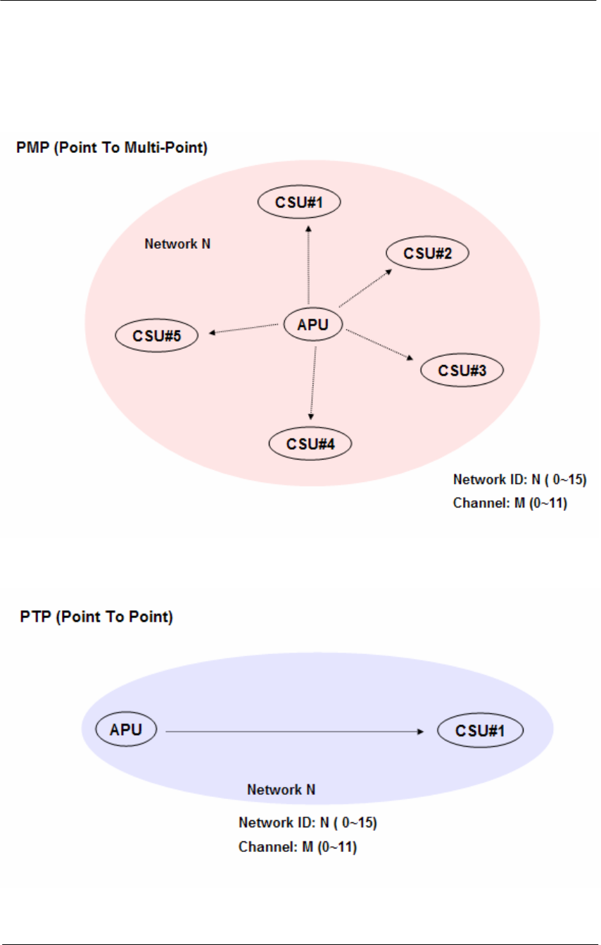
203
WLAN Cable Access Point 6220 NTPM99CA Rel 1.0 Issue 2 Nov 2004
Designing a wireless network
Figure A.13
PMP (Point to Multi-Point)
Figure A.14
PTP (Point to Point)
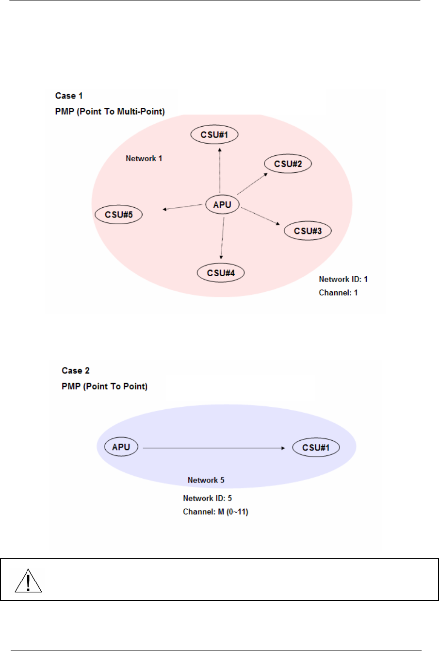
204
WLAN Cable Access Point 6220 NTPM99CA Rel 1.0 Issue 2 Nov 2004
Sample Networks
Figure A.15
PMP Topology
Figure A.16
PTP Topology
Even though Network ID and Channel are each different numbering concept,
It is convenient that both parameters are set to be the same number.
But, these tips can be changed in accordance with RF channel designing.
Only directional Antenna
Flat Panel Antenna
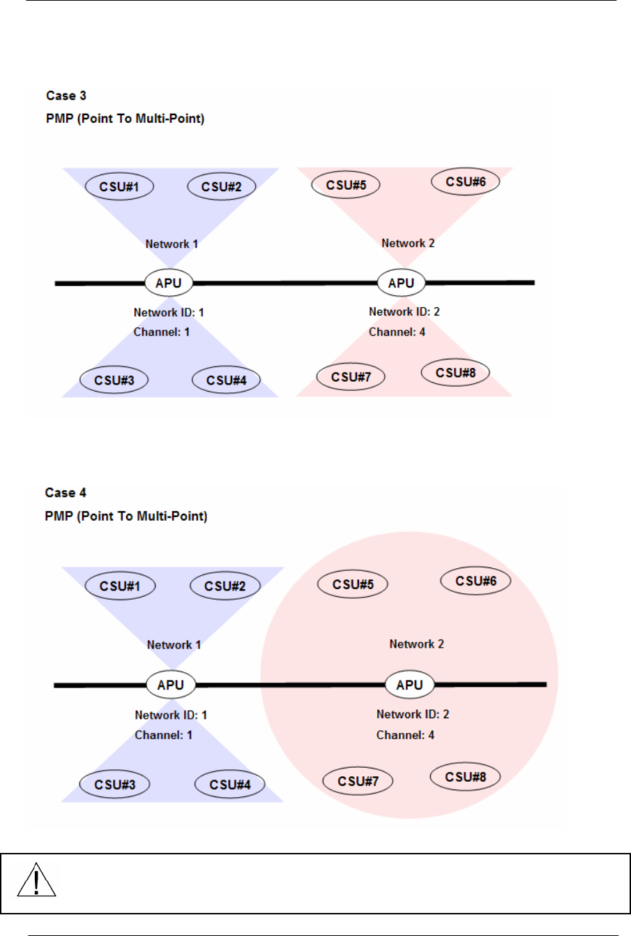
205
WLAN Cable Access Point 6220 NTPM99CA Rel 1.0 Issue 2 Nov 2004
Figure A.17
PMP Topology
Figure A.18
PMP Topology
Even though Network ID and Channel are each different numbering concept,
It is convenient that both parameters are set to be the same number.
But, these tips can be changed in accordance with RF channel designing.
Only Bi-directional Antenna
Bi & Omni directional Antenna

206
WLAN Cable Access Point 6220 NTPM99CA Rel 1.0 Issue 2 Nov 2004
Appendix G. SNMP MIB List & Example values
1: [Loaded: RFC1213-MIB] sysDescr.0 (octet string) KarlBridge/Router v4.44-00-
112900 SN-KNRG+a35CT3020551 V4.35
2: sysObjectID.0 (object identifier) kbridge-mib
3: sysUpTime.0 (timeticks) 6 days 00h:57m:11s.44th (52183144)
4: sysContact.0 (octet string) (zero-length)
5: sysName.0 (octet string) ABG-Proxim_ED
6: sysLocation.0 (octet string) (zero-length)
7: sysServices.0 (integer) 2
8: ifNumber.0 (integer) 2
9: ifIndex.1 (integer) 1
10: ifIndex.2 (integer) 2
11: ifDescr.1 (octet string) MACphyter Fast Ethernet
12: ifDescr.2 (octet string) AR5001-0000-0000 Wireless LAN Reference Card
13: ifType.1 (integer) ethernet-csmacd(6)
14: ifType.2 (integer) ethernet-csmacd(6)
15: ifMtu.1 (integer) 2042
16: ifMtu.2 (integer) 1522
17: ifSpeed.1 (gauge) 10000000
18: ifSpeed.2 (gauge) 54000000
19: ifPhysAddress.1 (octet string) 00.20.F6.04.03.A0 (hex)
20: ifPhysAddress.2 (octet string) 00.20.A6.4C.C7.51 (hex)
21: ifAdminStatus.1 (integer) up(1)
22: ifAdminStatus.2 (integer) up(1)
23: ifOperStatus.1 (integer) up(1)
24: ifOperStatus.2 (integer) up(1)
25: ifLastChange.1 (timeticks) 0 days 00h:00m:00s.00th (0)
26: ifLastChange.2 (timeticks) 0 days 00h:02m:00s.00th (12000)
27: ifInOctets.1 (counter) 1229704
28: ifInOctets.2 (counter) 86674413
29: ifInUcastPkts.1 (counter) 7078
30: ifInUcastPkts.2 (counter) 43463
31: ifInNUcastPkts.1 (counter) 4202
32: ifInNUcastPkts.2 (counter) 548012
33: ifInDiscards.1 (counter) 0
34: ifInDiscards.2 (counter) 41
35: ifInErrors.1 (counter) 0
36: ifInErrors.2 (counter) 2125
37: ifInUnknownProtos.1 (counter) 0
38: ifInUnknownProtos.2 (counter) 0
39: ifOutOctets.1 (counter) 8477301
40: ifOutOctets.2 (counter) 70108529
41: ifOutUcastPkts.1 (counter) 5799

207
WLAN Cable Access Point 6220 NTPM99CA Rel 1.0 Issue 2 Nov 2004
42: ifOutUcastPkts.2 (counter) 41946
43: ifOutNUcastPkts.1 (counter) 27181
44: ifOutNUcastPkts.2 (counter) 529297
45: ifOutDiscards.1 (counter) 0
46: ifOutDiscards.2 (counter) 1
47: ifOutErrors.1 (counter) 0
48: ifOutErrors.2 (counter) 0
49: ifOutQLen.1 (gauge) 0
50: ifOutQLen.2 (gauge) 0
51: [Loaded: EtherLike-MIB] ifSpecific.1 (object identifier) dot3
52: ifSpecific.2 (object identifier) iso.2.840.10036
53: ipForwarding.0 (integer) not-forwarding(2)
54: ipDefaultTTL.0 (integer) 255
55: ipInReceives.0 (counter) 52133
56: ipInHdrErrors.0 (counter) 0
57: ipInAddrErrors.0 (counter) 0
58: ipForwDatagrams.0 (counter) 0
59: ipInUnknownProtos.0 (counter) 0
60: ipInDiscards.0 (counter) 0
61: ipInDelivers.0 (counter) 34869
62: ipOutRequests.0 (counter) 34856
63: ipOutDiscards.0 (counter) 0
64: ipOutNoRoutes.0 (counter) 0
65: ipReasmTimeout.0 (integer) 0
66: ipReasmReqds.0 (counter) 0
67: ipReasmOKs.0 (counter) 0
68: ipReasmFails.0 (counter) 0
69: ipFragOKs.0 (counter) 0
70: ipFragFails.0 (counter) 0
71: ipFragCreates.0 (counter) 0
72: ipAdEntAddr.192.168.0.2 (ipaddress) 192.168.0.2
73: ipAdEntIfIndex.192.168.0.2 (integer) 1
74: ipAdEntNetMask.192.168.0.2 (ipaddress) 255.255.255.0
75: ipAdEntBcastAddr.192.168.0.2 (integer) 1
76: ipAdEntReasmMaxSize.192.168.0.2 (integer) 0
77: ipRouteDest.0.0.0.0 (ipaddress) 0.0.0.0
78: ipRouteIfIndex.0.0.0.0 (integer) 0
79: ipRouteMetric1.0.0.0.0 (integer) 1
80: ipRouteMetric2.0.0.0.0 (integer) -1
81: ipRouteMetric3.0.0.0.0 (integer) -1
82: ipRouteMetric4.0.0.0.0 (integer) -1
83: ipRouteNextHop.0.0.0.0 (ipaddress) 192.168.0.1
84: ipRouteType.0.0.0.0 (integer) indirect(4)
85: ipRouteProto.0.0.0.0 (integer) local(2)
86: ipRouteAge.0.0.0.0 (integer) 0
87: ipRouteMask.0.0.0.0 (ipaddress) 0.0.0.0

208
WLAN Cable Access Point 6220 NTPM99CA Rel 1.0 Issue 2 Nov 2004
88: ipRouteMetric5.0.0.0.0 (integer) -1
89: ipRouteInfo.0.0.0.0 (object identifier) (null-oid) 0.0
90: ipNetToMediaIfIndex.2.192.168.0.1 (integer) 2
91: ipNetToMediaIfIndex.2.192.168.0.50 (integer) 2
92: ipNetToMediaPhysAddress.2.192.168.0.1 (octet string) 00.01.24.70.0B.E2 (hex)
93: ipNetToMediaPhysAddress.2.192.168.0.50 (octet string) 00.50.8B.AD.3F.B2 (hex)
94: ipNetToMediaNetAddress.2.192.168.0.1 (ipaddress) 192.168.0.1
95: ipNetToMediaNetAddress.2.192.168.0.50 (ipaddress) 192.168.0.50
96: ipNetToMediaType.2.192.168.0.1 (integer) dynamic(3)
97: ipNetToMediaType.2.192.168.0.50 (integer) dynamic(3)
98: ipRoutingDiscards.0 (counter) 0
99: icmpInMsgs.0 (counter) 33234
100: icmpInErrors.0 (counter) 0
101: icmpInDestUnreachs.0 (counter) 0
102: icmpInTimeExcds.0 (counter) 30928
103: icmpInParmProbs.0 (counter) 0
104: icmpInSrcQuenchs.0 (counter) 19904
105: icmpInRedirects.0 (counter) 2000
106: icmpInEchos.0 (counter) 33234
107: icmpInEchoReps.0 (counter) 0
108: icmpInTimestamps.0 (counter) 0
109: icmpInTimestampReps.0 (counter) 0
110: icmpInAddrMasks.0 (counter) 0
111: icmpInAddrMaskReps.0 (counter) 0
112: icmpOutMsgs.0 (counter) 33234
113: icmpOutErrors.0 (counter) 0
114: icmpOutDestUnreachs.0 (counter) 3
115: icmpOutTimeExcds.0 (counter) 0
116: icmpOutParmProbs.0 (counter) 0
117: icmpOutSrcQuenchs.0 (counter) 30928
118: icmpOutRedirects.0 (counter) 40960
119: icmpOutEchos.0 (counter) 0
120: icmpOutEchoReps.0 (counter) 33234
121: icmpOutTimestamps.0 (counter) 0
122: icmpOutTimestampReps.0 (counter) 0
123: icmpOutAddrMasks.0 (counter) 0
124: icmpOutAddrMaskReps.0 (counter) 0
125: udpInDatagrams.0 (counter) 1699
126: udpNoPorts.0 (counter) 3
127: udpInErrors.0 (counter) 0
128: udpOutDatagrams.0 (counter) 1685
129: udpLocalAddress.0.0.0.0.161 (ipaddress) 0.0.0.0
130: udpLocalPort.0.0.0.0.161 (integer) 161
131: dot3StatsIndex.1 (integer) 1
132: dot3StatsIndex.2 (integer) 2
133: dot3StatsAlignmentErrors.1 (counter) 0

209
WLAN Cable Access Point 6220 NTPM99CA Rel 1.0 Issue 2 Nov 2004
134: dot3StatsAlignmentErrors.2 (counter) 0
135: dot3StatsFCSErrors.1 (counter) 0
136: dot3StatsFCSErrors.2 (counter) 0
137: dot3StatsSingleCollisionFrames.1 (counter) 1647
138: dot3StatsSingleCollisionFrames.2 (counter) 0
139: dot3StatsMultipleCollisionFrames.1 (counter) 545
140: dot3StatsMultipleCollisionFrames.2 (counter) 0
141: dot3StatsSQETestErrors.1 (counter) 0
142: dot3StatsSQETestErrors.2 (counter) 0
143: dot3StatsDeferredTransmissions.1 (counter) 18
144: dot3StatsDeferredTransmissions.2 (counter) 0
145: dot3StatsLateCollisions.1 (counter) 0
146: dot3StatsLateCollisions.2 (counter) 0
147: dot3StatsExcessiveCollisions.1 (counter) 0
148: dot3StatsExcessiveCollisions.2 (counter) 0
149: dot3StatsInternalMacTransmitErrors.1 (counter) 0
150: dot3StatsInternalMacTransmitErrors.2 (counter) 0
151: dot3StatsCarrierSenseErrors.1 (counter) 0
152: dot3StatsCarrierSenseErrors.2 (counter) 0
153: dot3StatsFrameTooLongs.1 (counter) 0
154: dot3StatsFrameTooLongs.2 (counter) 0
155: dot3StatsInternalMacReceiveErrors.1 (counter) 0
156: dot3StatsInternalMacReceiveErrors.2 (counter) 0
157: snmpInPkts.0 (counter) 1298
158: snmpOutPkts.0 (counter) 1298
159: snmpInBadVersions.0 (counter) 0
160: snmpInBadCommunityNames.0 (counter) 0
161: snmpInBadCommunityUses.0 (counter) 3
162: snmpInASNParseErrs.0 (counter) 0
163: snmpInTooBigs.0 (counter) 0
164: snmpInNoSuchNames.0 (counter) 0
165: snmpInBadValues.0 (counter) 0
166: snmpInReadOnlys.0 (counter) 0
167: snmpInGenErrs.0 (counter) 0
168: snmpInTotalReqVars.0 (counter) 1511
169: snmpInTotalSetVars.0 (counter) 4
170: snmpInGetRequests.0 (counter) 97
171: snmpInGetNexts.0 (counter) 1211
172: snmpInSetRequests.0 (counter) 4
173: snmpInGetResponses.0 (counter) 0
174: snmpInTraps.0 (counter) 0
175: snmpOutTooBigs.0 (counter) 0
176: snmpOutNoSuchNames.0 (counter) 3
177: snmpOutBadValues.0 (counter) 0
178: snmpOutGenErrs.0 (counter) 0
179: snmpOutGetRequests.0 (counter) 0

210
WLAN Cable Access Point 6220 NTPM99CA Rel 1.0 Issue 2 Nov 2004
180: snmpOutGetNexts.0 (counter) 0
181: snmpOutSetRequests.0 (counter) 0
182: snmpOutGetResponses.0 (counter) 1322
183: snmpOutTraps.0 (counter) 0
184: snmpEnableAuthenTraps.0 (integer) enabled(1)
185: mib-2.17.1.1.0 (octet string) 00.20.F6.04.03.A0 (hex)
186: mib-2.17.1.2.0 (integer) 2
187: mib-2.17.1.3.0 (integer) 2
188: mib-2.17.1.4.1.1.1 (integer) 1
189: mib-2.17.1.4.1.1.2 (integer) 2
190: mib-2.17.1.4.1.2.1 (integer) 1
191: mib-2.17.1.4.1.2.2 (integer) 2
192: mib-2.17.1.4.1.3.1 (object identifier) (null-oid) 0.0
193: mib-2.17.1.4.1.3.2 (object identifier) (null-oid) 0.0
194: mib-2.17.1.4.1.4.1 (counter) 0
195: mib-2.17.1.4.1.4.2 (counter) 0
196: mib-2.17.1.4.1.5.1 (counter) 0
197: mib-2.17.1.4.1.5.2 (counter) 0
198: mib-2.17.4.1.0 (counter) 0
199: mib-2.17.4.2.0 (integer) 300
200: mib-2.17.4.3.1.1.0.1.36.112.11.226 (octet string) 00.01.24.70.0B.E2 (hex)
201: mib-2.17.4.3.1.1.0.32.246.4.3.160 (octet string) 00.20.F6.04.03.A0 (hex)
202: mib-2.17.4.3.1.1.0.32.246.4.12.163 (octet string) 00.20.F6.04.0C.A3 (hex)
203: mib-2.17.4.3.1.1.0.32.246.4.26.159 (octet string) 00.20.F6.04.1A.9F (hex)
204: mib-2.17.4.3.1.1.0.32.246.4.34.23 (octet string) 00.20.F6.04.22.17 (hex)
205: mib-2.17.4.3.1.1.0.32.246.4.34.75 (octet string) 00.20.F6.04.22.4B (hex)
206: mib-2.17.4.3.1.1.0.64.244.114.215.152 (octet string) 00.40.F4.72.D7.98 (hex)
207: mib-2.17.4.3.1.1.0.80.139.173.63.178 (octet string) 00.50.8B.AD.3F.B2 (hex)
208: mib-2.17.4.3.1.1.0.80.186.71.245.19 (octet string) 00.50.BA.47.F5.13 (hex)
209: mib-2.17.4.3.1.2.0.1.36.112.11.226 (integer) 2
210: mib-2.17.4.3.1.2.0.32.246.4.3.160 (integer) 2
211: mib-2.17.4.3.1.2.0.32.246.4.12.163 (integer) 2
212: mib-2.17.4.3.1.2.0.32.246.4.26.159 (integer) 2
213: mib-2.17.4.3.1.2.0.32.246.4.34.23 (integer) 2
214: mib-2.17.4.3.1.2.0.32.246.4.34.75 (integer) 2
215: mib-2.17.4.3.1.2.0.64.244.114.215.152 (integer) 2
216: mib-2.17.4.3.1.2.0.80.139.173.63.178 (integer) 2
217: mib-2.17.4.3.1.2.0.80.186.71.245.19 (integer) 1
218: mib-2.17.4.3.1.3.0.1.36.112.11.226 (integer) 5
219: mib-2.17.4.3.1.3.0.32.246.4.3.160 (integer) 3
220: mib-2.17.4.3.1.3.0.32.246.4.12.163 (integer) 3
221: mib-2.17.4.3.1.3.0.32.246.4.26.159 (integer) 3
222: mib-2.17.4.3.1.3.0.32.246.4.34.23 (integer) 3
223: mib-2.17.4.3.1.3.0.32.246.4.34.75 (integer) 3
224: mib-2.17.4.3.1.3.0.64.244.114.215.152 (integer) 3
225: mib-2.17.4.3.1.3.0.80.139.173.63.178 (integer) 3

211
WLAN Cable Access Point 6220 NTPM99CA Rel 1.0 Issue 2 Nov 2004
226: mib-2.17.4.3.1.3.0.80.186.71.245.19 (integer) 3
227: mib-2.17.4.4.1.1.1 (integer) 1
228: mib-2.17.4.4.1.1.2 (integer) 2
229: mib-2.17.4.4.1.2.1 (integer) 0
230: mib-2.17.4.4.1.2.2 (integer) 0
231: mib-2.17.4.4.1.3.1 (counter) 11280
232: mib-2.17.4.4.1.3.2 (counter) 29716
233: mib-2.17.4.4.1.4.1 (counter) 29716
234: mib-2.17.4.4.1.4.2 (counter) 11280
235: mib-2.17.4.4.1.5.1 (counter) 0
236: mib-2.17.4.4.1.5.2 (counter) 0
237: karlnet.1.1.0 (integer) 0
238: karlnet.1.2.0 (integer) 32
239: karlnet.1.3.0 (integer) 25
240: karlnet.1.4.0 (integer) 20
241: karlnet.1.5.0 (ipaddress) 198.17.74.250
242: karlnet.1.6.0 (integer) 0
243: karlnet.1.7.0 (integer) 0
244: karlnet.1.8.0 (integer) 0
245: karlnet.1.9.0 (integer) 0
246: karlnet.1.10.0 (integer) 0
247: karlnet.1.11.0 (integer) 0
248: karlnet.1.12.0 (integer) -10000
249: karlnet.1.13.0 (integer) 0
250: karlnet.1.14.0 (integer) 0
251: karlnet.1.15.0 (integer) 0
252: karlnet.1.16.0 (integer) 0
253: karlnet.1.17.0 (integer) 0
254: karlnet.1.18.0 (integer) 0
255: karlnet.1.19.0 (integer) 0
256: karlnet.1.20.0 (integer) 0
257: karlnet.1.21.0 (integer) 0
258: karlnet.1.22.0 (integer) 0
259: karlnet.1.23.0 (integer) 0
260: karlnet.1.24.0 (integer) 0
261: karlnet.1.25.0 (integer) 0
262: karlnet.1.26.0 (integer) 0
263: karlnet.1.27.0 (integer) 0
264: kbWirelessStationNumber.0 (integer) 1
265: kbWirelessStationIndex.1 (integer) 1
266: kbWirelessStationInterfaceNumber.1 (integer) 2
267: kbWirelessStationName.1 (octet string) 5.8 ISP_Base
268: kbWirelessStationExclHellos.1 (counter) 520801
269: kbWirelessStationGoodHellos.1 (counter) 4
270: kbWirelessStationLowHellos.1 (counter) 0
271: kbWirelessStationSignalLevel.1 (integer) 90

212
WLAN Cable Access Point 6220 NTPM99CA Rel 1.0 Issue 2 Nov 2004
272: kbWirelessStationNoiseLevel.1 (integer) 10
273: kbWirelessStationSignalQuality.1 (integer) 0
274: kbWirelessStationPktTransmits.1 (counter) 49643
275: kbWirelessStationMACAddress.1 (octet string) 00.01.24.70.0B.E2 (hex)
276: kbWirelessStationTransmits.1 (counter) 48696
277: kbWirelessStationBadTransmits.1 (counter) 0
278: kbWirelessStationReTransmits.1 (counter) 179
279: kbWirelessStationIPAddress.1 (ipaddress) 10.0.1.129
280: kbWirelessStationType.1 (integer) tc_Base_Station(3)
281: kbWirelessStationSNR.1 (integer) excellent_SNR(4)
282: kbWirelessStationState.1 (integer) online(1)
283: kbWirelessPoll.1 (counter) 0
284: kbWirelessPollData.1 (counter) 0
285: kbWirelessPollNoData.1 (counter) 0
286: kbWirelessPollMoreData.1 (counter) 0
287: kbWirelessPollTimeouts.1 (counter) 0
288: kbWirelessPollOfflines.1 (counter) 0
289: kbWirelessTestTime.1 (integer) 0
290: kbWirelessTestInterval.1 (integer) 0
291: kbWirelessTestPacketSize.1 (integer) 0
292: kbWirelessTestOurTx.1 (counter) 0
293: kbWirelessTestOurRx.1 (counter) 0
294: kbWirelessTestHisTx.1 (counter) 0
295: kbWirelessTestHisRx.1 (counter) 0
296: kbWirelessTestOurCurSignalLevel.1 (integer) 0
297: kbWirelessTestOurCurNoiseLevel.1 (integer) 0
298: kbWirelessTestOurCurSignalQuality.1 (integer) 0
299: kbWirelessTestOurCurSNR.1 (integer) 0
300: kbWirelessTestOurMinSignalLevel.1 (integer) 0
301: kbWirelessTestOurMinNoiseLevel.1 (integer) 0
302: kbWirelessTestOurMinSignalQuality.1 (integer) 0
303: kbWirelessTestOurMinSNR.1 (integer) 0
304: kbWirelessTestOurMaxSignalLevel.1 (integer) 0
305: kbWirelessTestOurMaxNoiseLevel.1 (integer) 0
306: kbWirelessTestOurMaxSignalQuality.1 (integer) 0
307: kbWirelessTestOurMaxSNR.1 (integer) 0
308: kbWirelessTestHisCurSignalLevel.1 (integer) 0
309: kbWirelessTestHisCurNoiseLevel.1 (integer) 0
310: kbWirelessTestHisCurSignalQuality.1 (integer) 0
311: kbWirelessTestHisCurSNR.1 (integer) 0
312: kbWirelessTestHisMinSignalLevel.1 (integer) 0
313: kbWirelessTestHisMinNoiseLevel.1 (integer) 0
314: kbWirelessTestHisMinSignalQuality.1 (integer) 0
315: kbWirelessTestHisMinSNR.1 (integer) 0
316: kbWirelessTestHisMaxSignalLevel.1 (integer) 0
317: kbWirelessTestHisMaxNoiseLevel.1 (integer) 0

213
WLAN Cable Access Point 6220 NTPM99CA Rel 1.0 Issue 2 Nov 2004
318: kbWirelessTestHisMaxSignalQuality.1 (integer) 0
319: kbWirelessTestHisMaxSNR.1 (integer) 0
320: kbWirelessTestLinkUp.1 (integer) down(0)
321: kbWirelessTestLostLink.1 (integer) 0
322: kbWirelessTestLostTestPkts.1 (counter) 0
323: kbWirelessStationRadioType.1 (integer) waveLAN_I(0)
324: kbWirelessRecordType.1 (integer) turboCell(2)
325: kbWirelessStationPktReceives.1 (counter) 70964
326: kbWirelessStationReceives.1 (counter) 0
327: kbWirelessStationBytesReceives.1 (counter) 11395282
328: kbWirelessStationBytesTransmits.1 (counter) 4239031
329: kbWirelessRegistrationRecord.1 (octet string)
00.00.00.00.02.00.AE.01.00.01.24.70.0B.E2.07.00.0A.00.00.00.B8.82.00.00.00.08.00.0
0.00.00.00.00.00.00.00.00.E8.03.14.00.6C.BE.6D.BE.00.00.8F.B9.0A.00.01.81.9A.2E.
00.00.35.2E.38.20.49.53.50.5F.42.61.73.65.00.00.00.00.00.00.00.00.00.00.00.00.00.00.
00.00.00.00.00.00.00.00.00.00.6D.BE.00.00.B3.00.00.00.00.00.00.00.38.15.01.00.22.C
2.00.00.80.E1.AD.00.11.AF.40.00.00.00.00.00.00.00.00.00.00.00.00.00.00.00.00.00.00.
00.00.00.00.00.00.00.5A.0A.00.00.62.F2.07.00.04.00.00.00.00.00.00.00.00.00.00.00.00
.00.00.00.00.00.00.00.00.00.00.00.00.00.00.00.00.00.00.00.00.00.00.00.00.00.00.00.00.
00.00.00.00.00.00.00.00.00.00.00.00.00.00.00.00.00.00.00.00.00.00.00.00.00.00.00.00.
00.00.00.00.00.00.00.00.00.00.00.00.00.00.00.00.00.00.00.00.00.00.00.00.00.00.00.00.
00.00.00.00.00.00.00.00.00.00.00.00.00.00.00 (hex)
330: kbWirelessStationFragmentDiscards.1 (counter) 0
331: kbWirelessStationFragmentMissings.1 (counter) 0
332: kbWirelessStationFragmentLostFrames.1 (counter) 0
333: kbWirelessStationFragmentErrors.1 (counter) 0
334: kbWirelessLocalInterfaceType.1 (integer) 1
335: kbWirelessLocalInterfaceType.2 (integer) 4
336: kbWirelessTestExploreTime.1 (integer) 0
337: kbWirelessTestExploreTime.2 (integer) 0
338: kbWirelessTestExploreRate.1 (integer) 0
339: kbWirelessTestExploreRate.2 (integer) 0