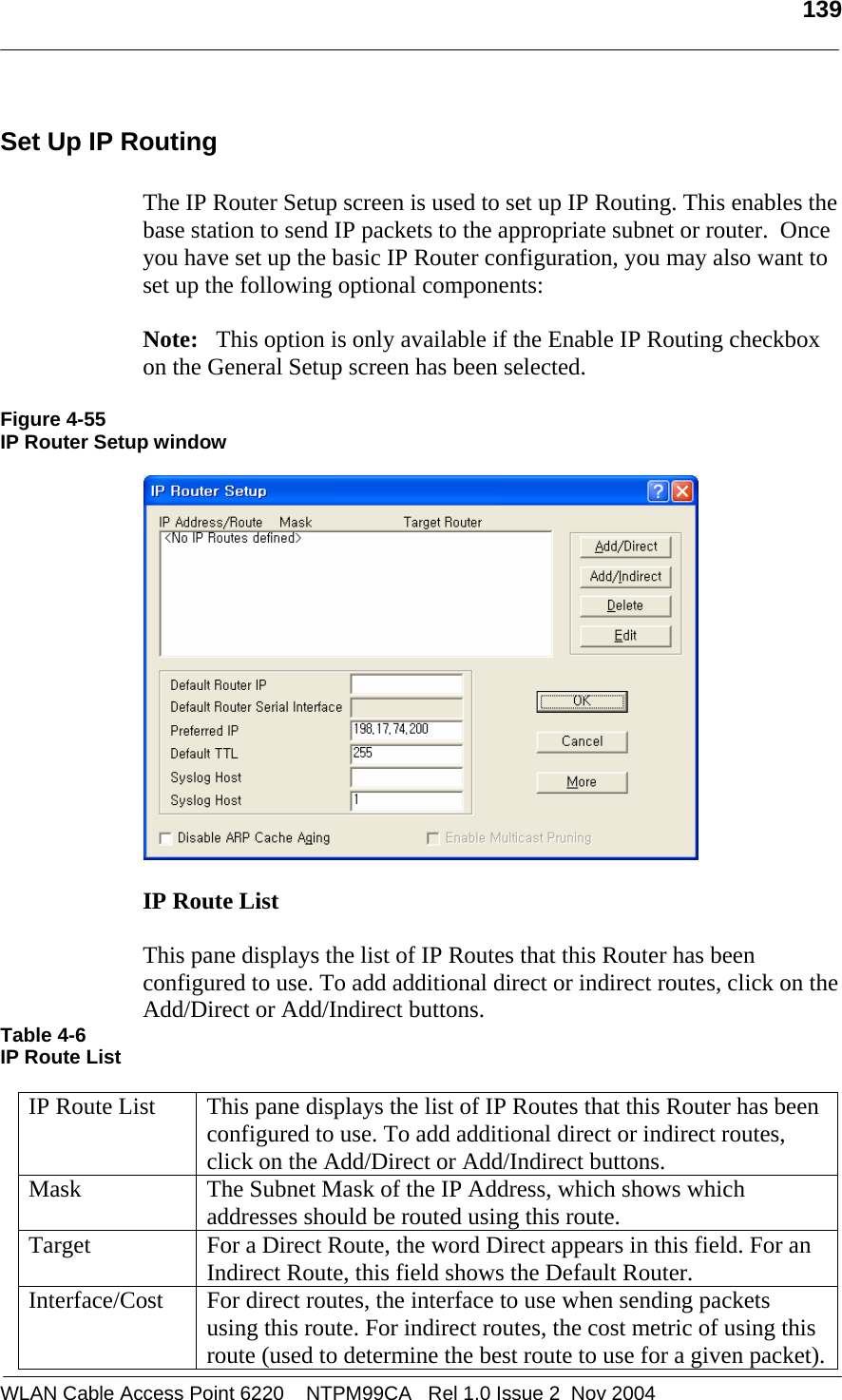
MTI WCAP6220CSU WiFi Transceiver User Manual Part 2
MTI Co., Ltd. WiFi Transceiver Users Manual Part 2
UserManual.wiki
>
MTI
>
WCAP6220CSU User Manual
>
Users Manual Part 2
Contents
1.
Users Manual Part 1
2.
Users Manual Part 2
Users Manual Part 2
Navigation menu
Upload a User Manual
Namespaces
Wiki Guide
HTML
PDF
Info
Views
User Manual
Discussion / Help
Navigation
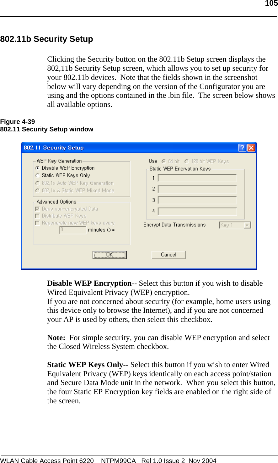
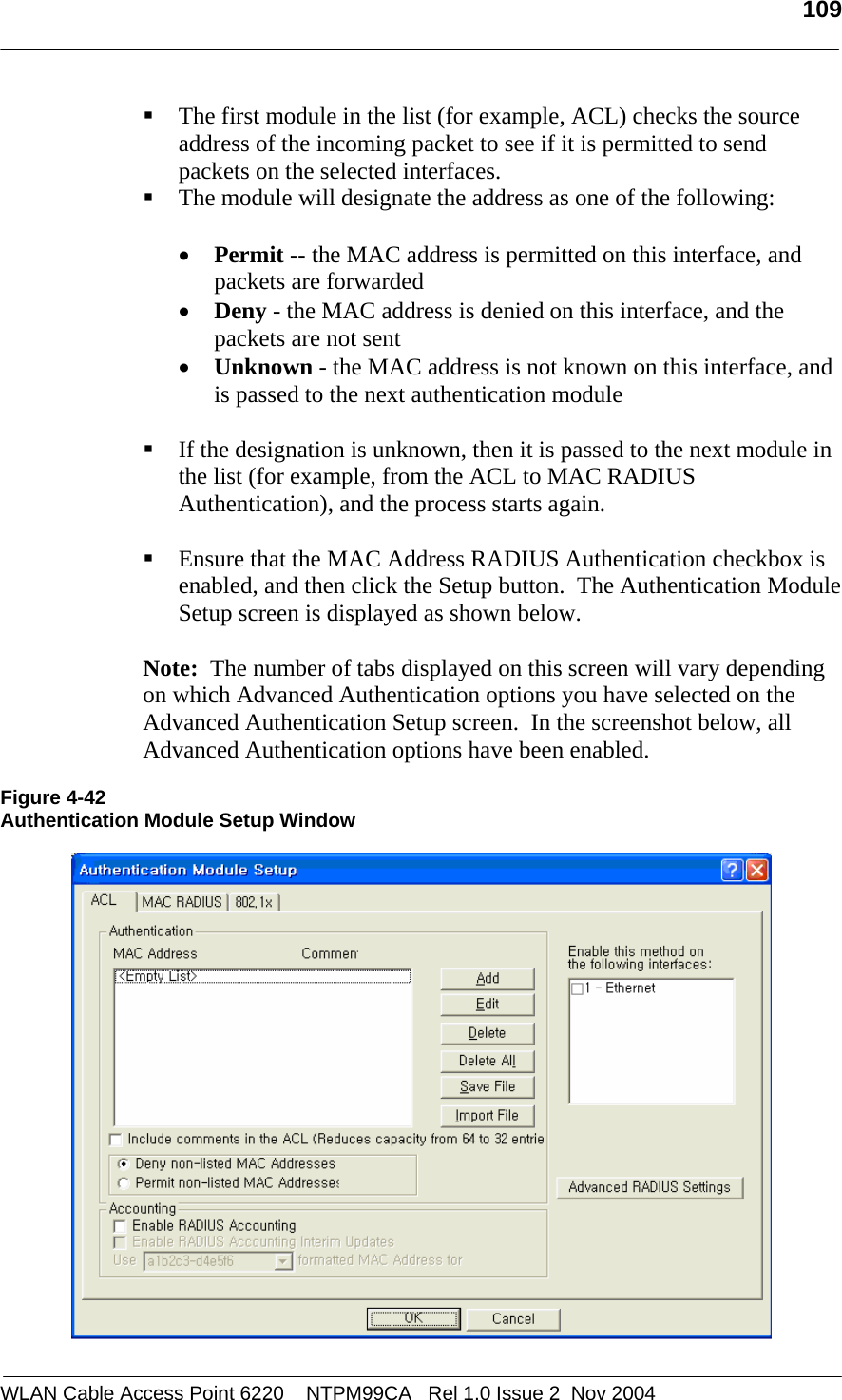
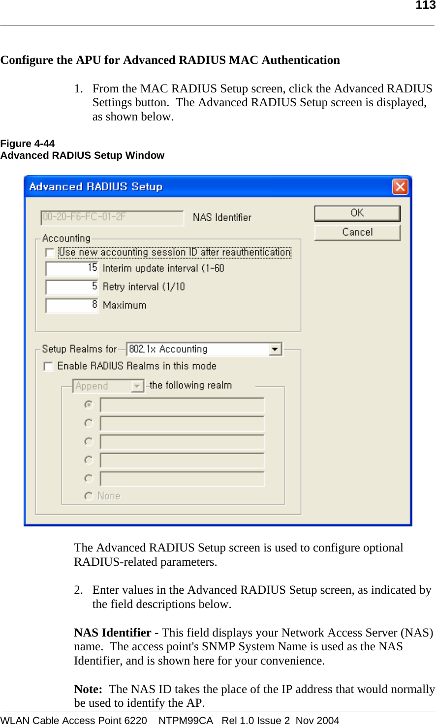

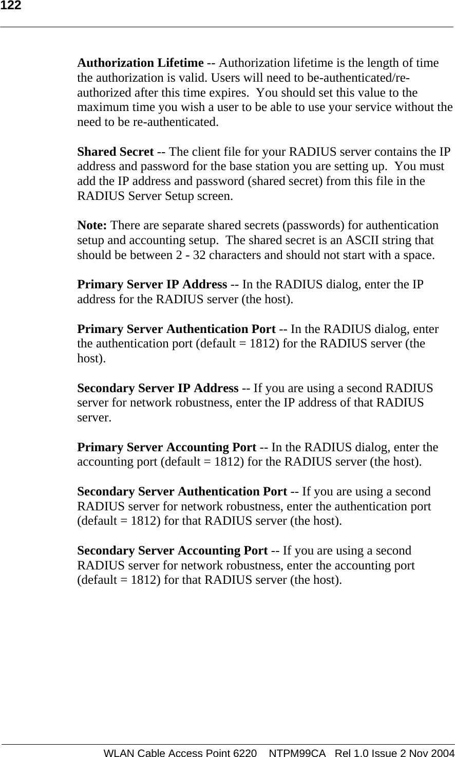

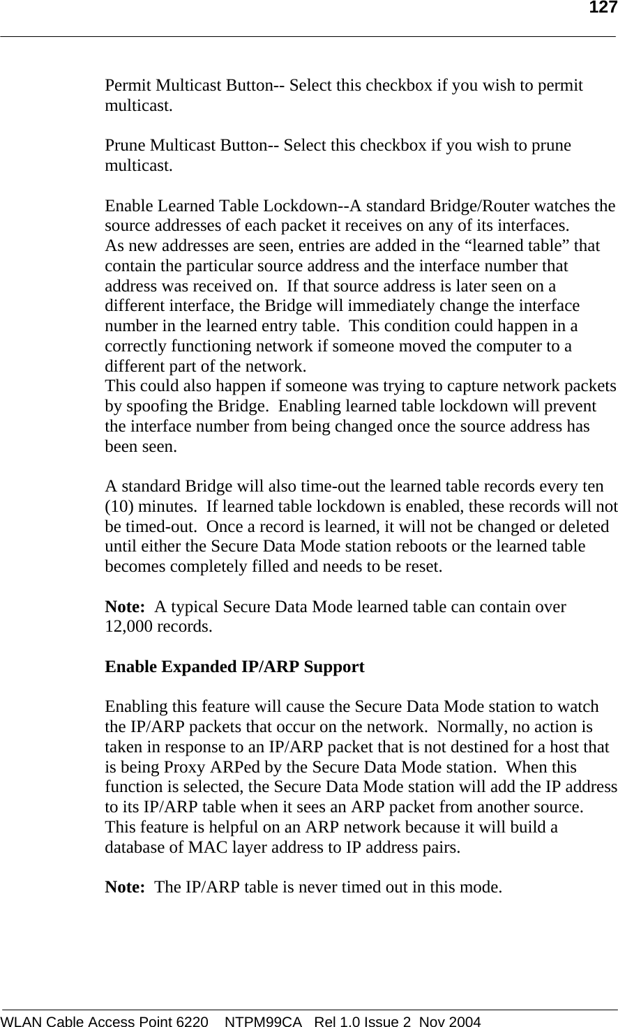
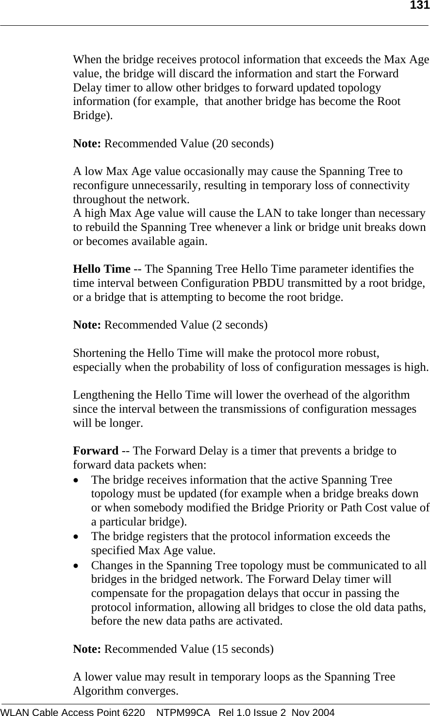
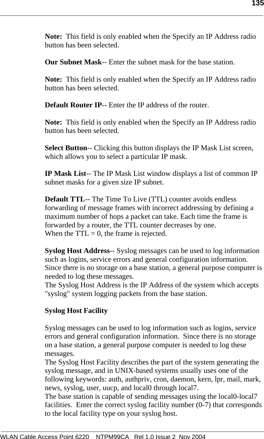
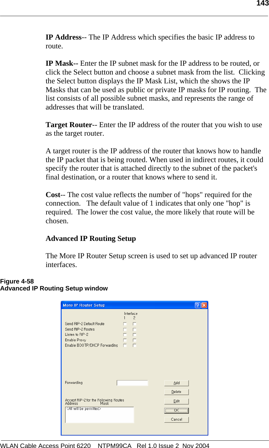
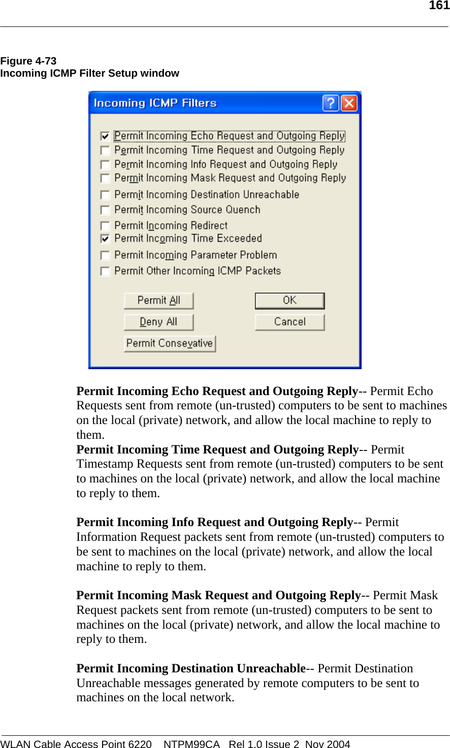
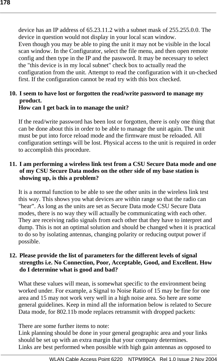
![157 WLAN Cable Access Point 6220 NTPM99CA Rel 1.0 Issue 2 Nov 2004 Log Non UDP/TCP & Source Routed & Fragment Packets-- Select this option if you want to log to the syslog for all packets that are not UDP/TCP, are source-routed, or are fragmented. Trap Non UDP/TCP & Source Routed & Fragment Packets-- Select this option if you want the Secure Data Mode Station to SNMP Trap messages whenever a non-TCP or non-UDP, Source Routed, or Fragmented IP packet is received by the Secure Data Mode Station. SNMP Traps are sent to the SNMP Trap Host specified in SNMP Setup. Record Non UDP/TCP & Source Routed & Fragment Packets-- Select this option if you want the Secure Data Mode Station to record all packets that are not UDP/TCP, are source-routed, or are fragmented. IP Protocol Filters Clicking the IP Protocols button displays the IP Protocol Filters screen, which allows you to set the IP protocols to which a given filter will be applied. Select the filter you want to modify on the Firewall Setup screen, and click the IP Protocols button. Less Frequently Used IP Protocols-- This list displays some of the less commonly used protocols that run over IP If you wish to filter one of these protocols, select it and click the [ -> ] button. Then set the action to take using the Protocol Options button. Selected IP Protocols-- Select one of the protocols added to the list and then click the Protocol Options button to set the action for this protocol. Select “All Protocols" or "All Other Protocols" to set a default action when a packet is received from a protocol for which no action has been defined. Figure 4-70 IP Protocol Filter Setup window](https://usermanual.wiki/MTI/WCAP6220CSU.Users-Manual-Part-2/User-Guide-500120-Page-55.png)
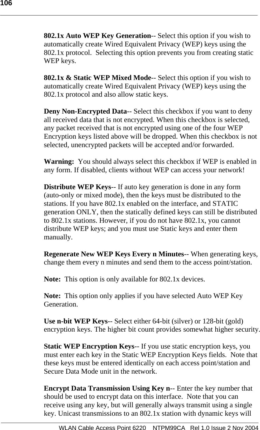
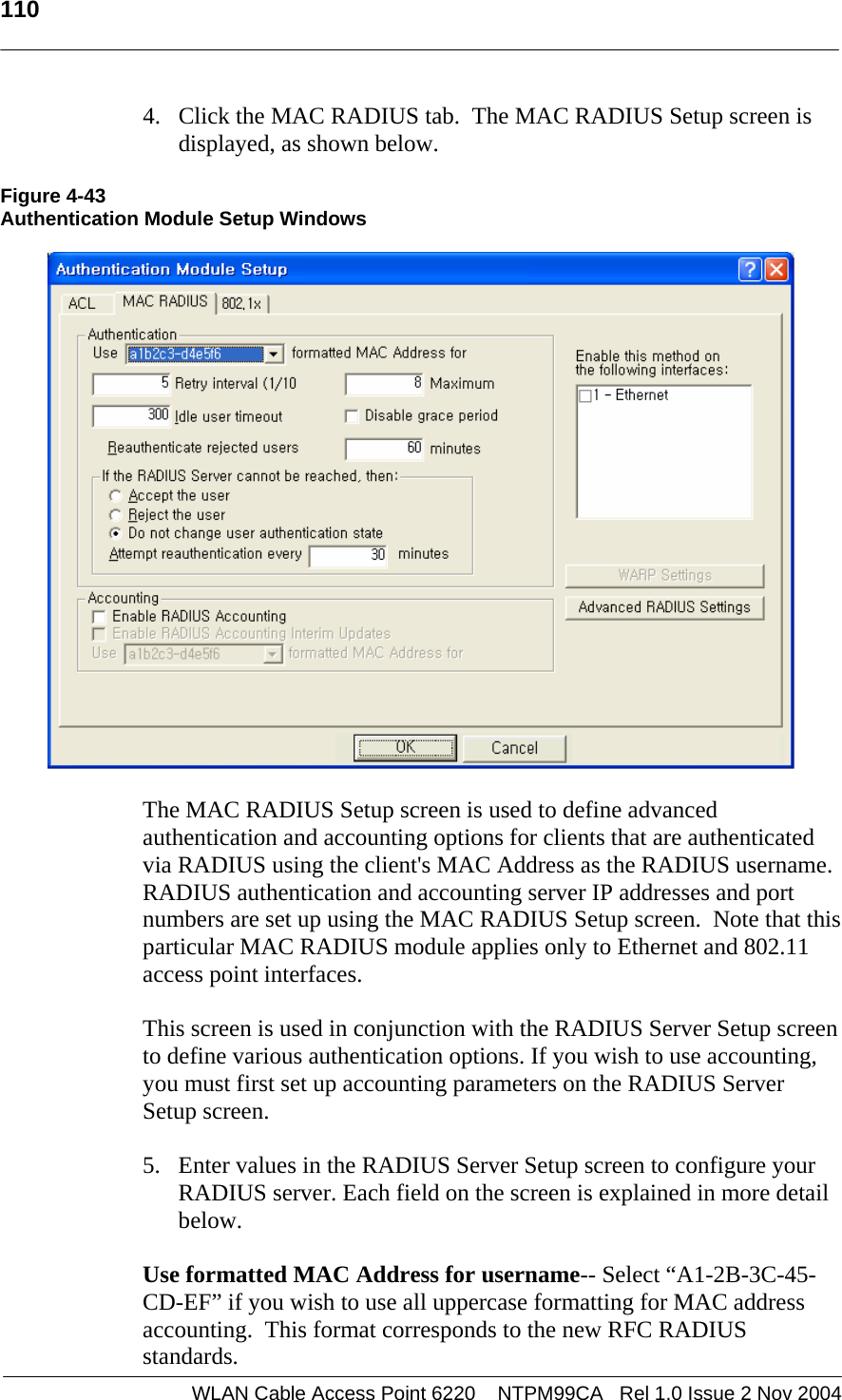
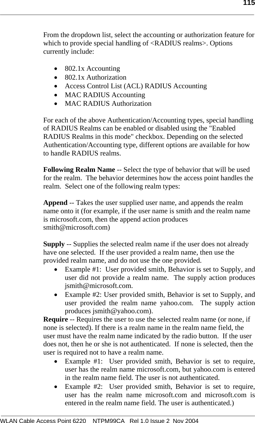
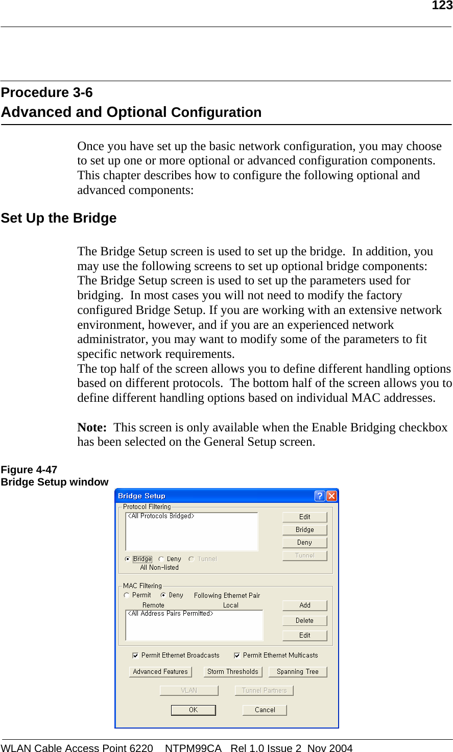
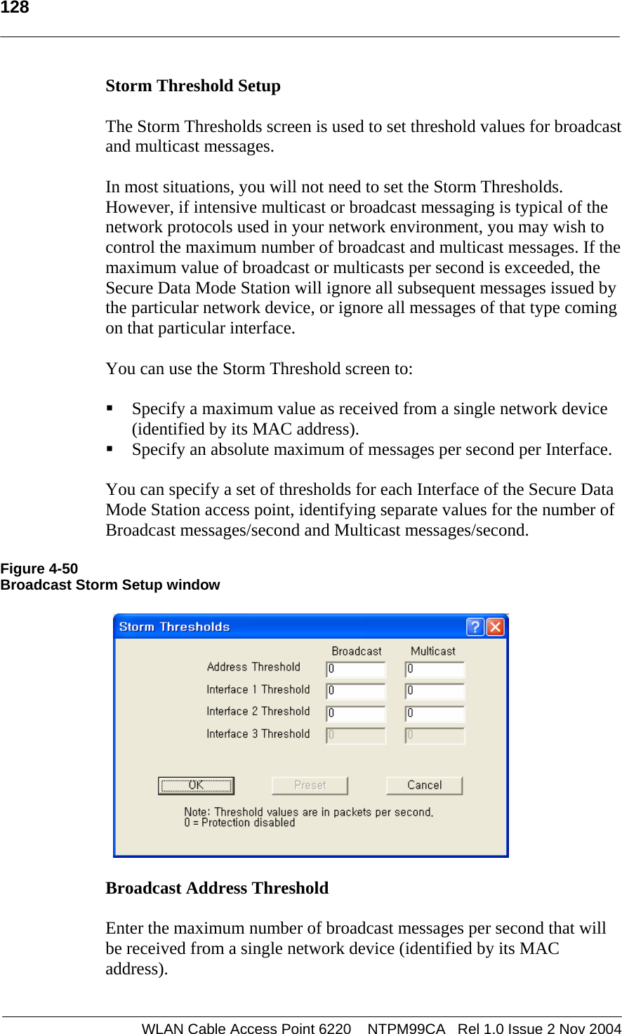
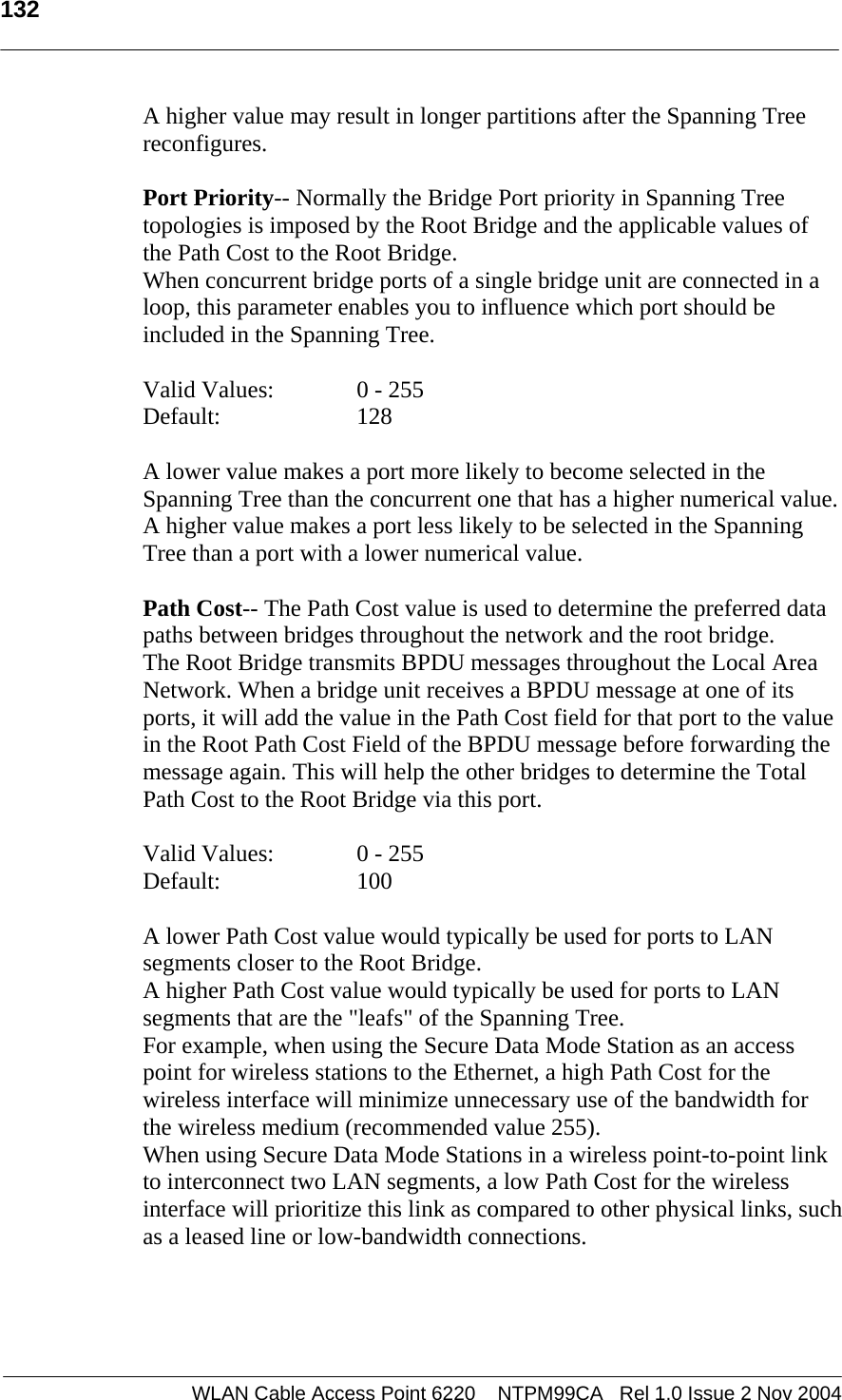
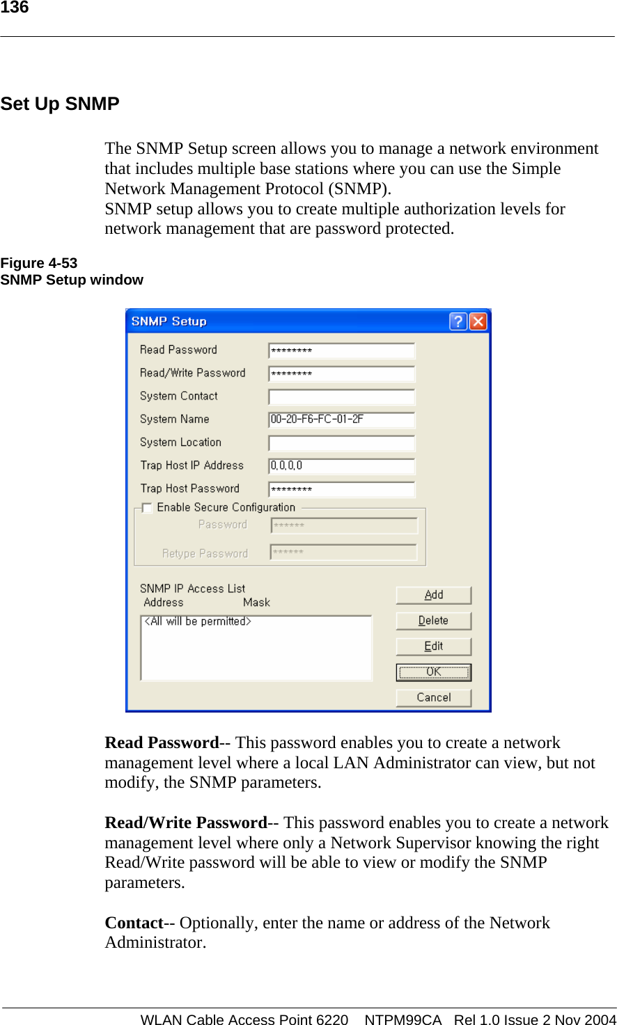
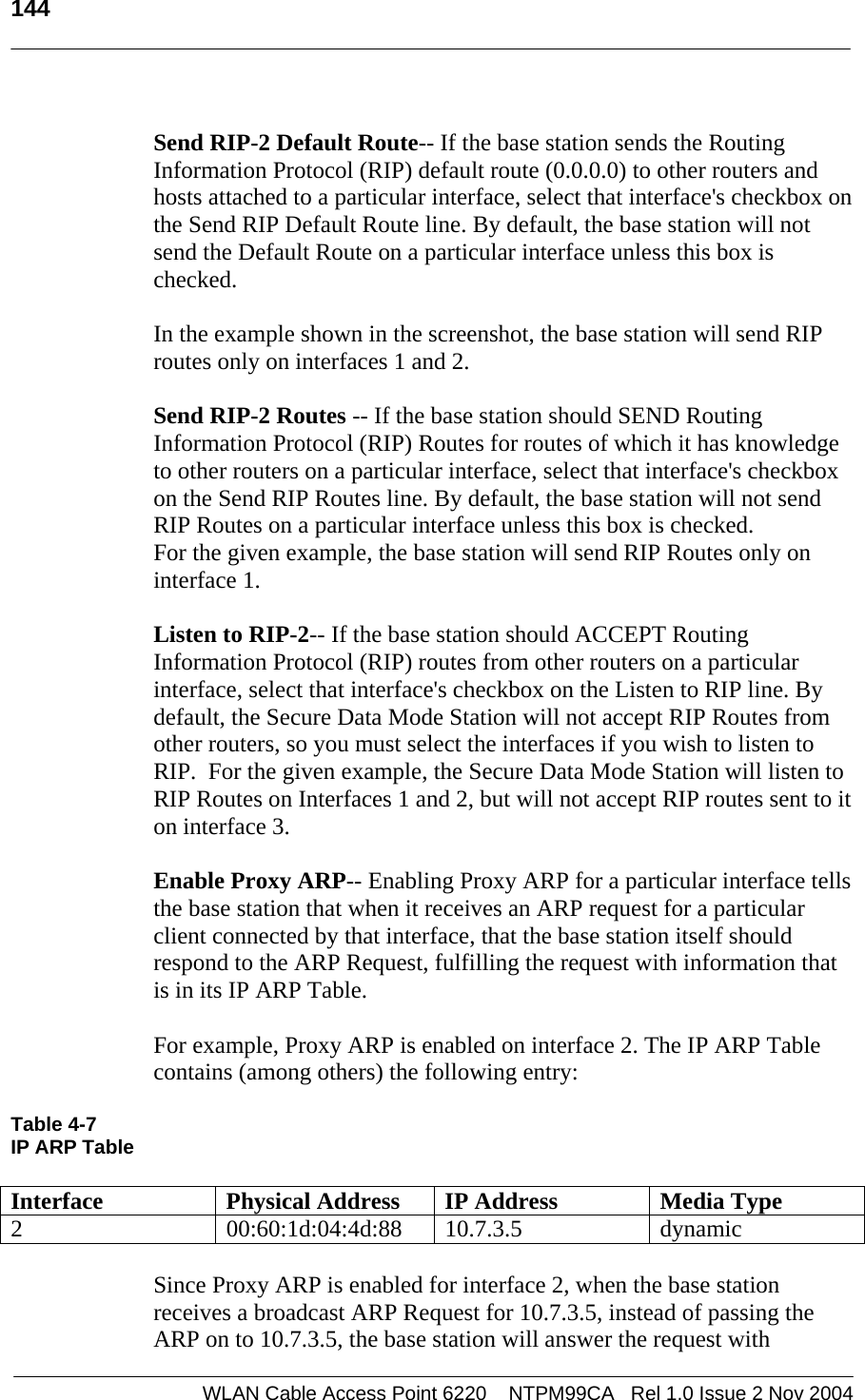
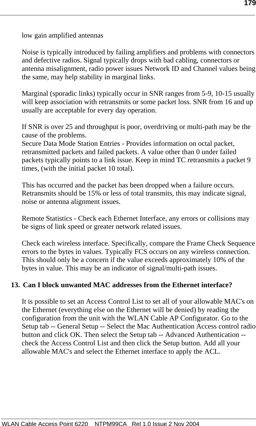
![158 WLAN Cable Access Point 6220 NTPM99CA Rel 1.0 Issue 2 Nov 2004 Custom IP Protocol-- If you wish to explicitly allow or deny access to a given IP protocol not listed in the two panels above, you can add that protocol to the list by simply typing it in the Custom IP Protocol field and clicking on the right arrow button [->] next to the text field. You do not need to add a protocol to the list unless you have specific requirements for that particular protocol. IP Protocol Options Clicking the Protocol Options button displays the IP Protocol Options screen, which allows you to define an action to take when data using that protocol is sent or received. When you select a protocol to filter, you will need to define an action to take when data using that protocol is sent or received. Initially, you will need to indicate whether you wish to permit or deny that protocol. In addition, you can optionally choose to log, trap, or record all packets, and to dynamically deny all other protocols. Figure 4-71 IP Protocol Option Setup window Permit All Other Protocols Button-- Select this button if you wish to permit all other protocols. Deny All Other Protocols Button-- Select this button if you wish to deny all other protocols. Log All Packets-- Select this checkbox if you wish to log all packets. Trap All Packets-- Select this checkbox if you wish to trap all packets. Record All Packets-- Select this checkbox if you wish to record all packets. Dynamically Deny All Other Protocols-- Select this checkbox if you wish to dynamically deny all other protocols.](https://usermanual.wiki/MTI/WCAP6220CSU.Users-Manual-Part-2/User-Guide-500120-Page-56.png)
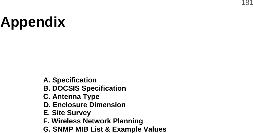

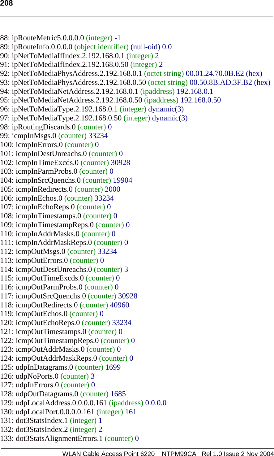
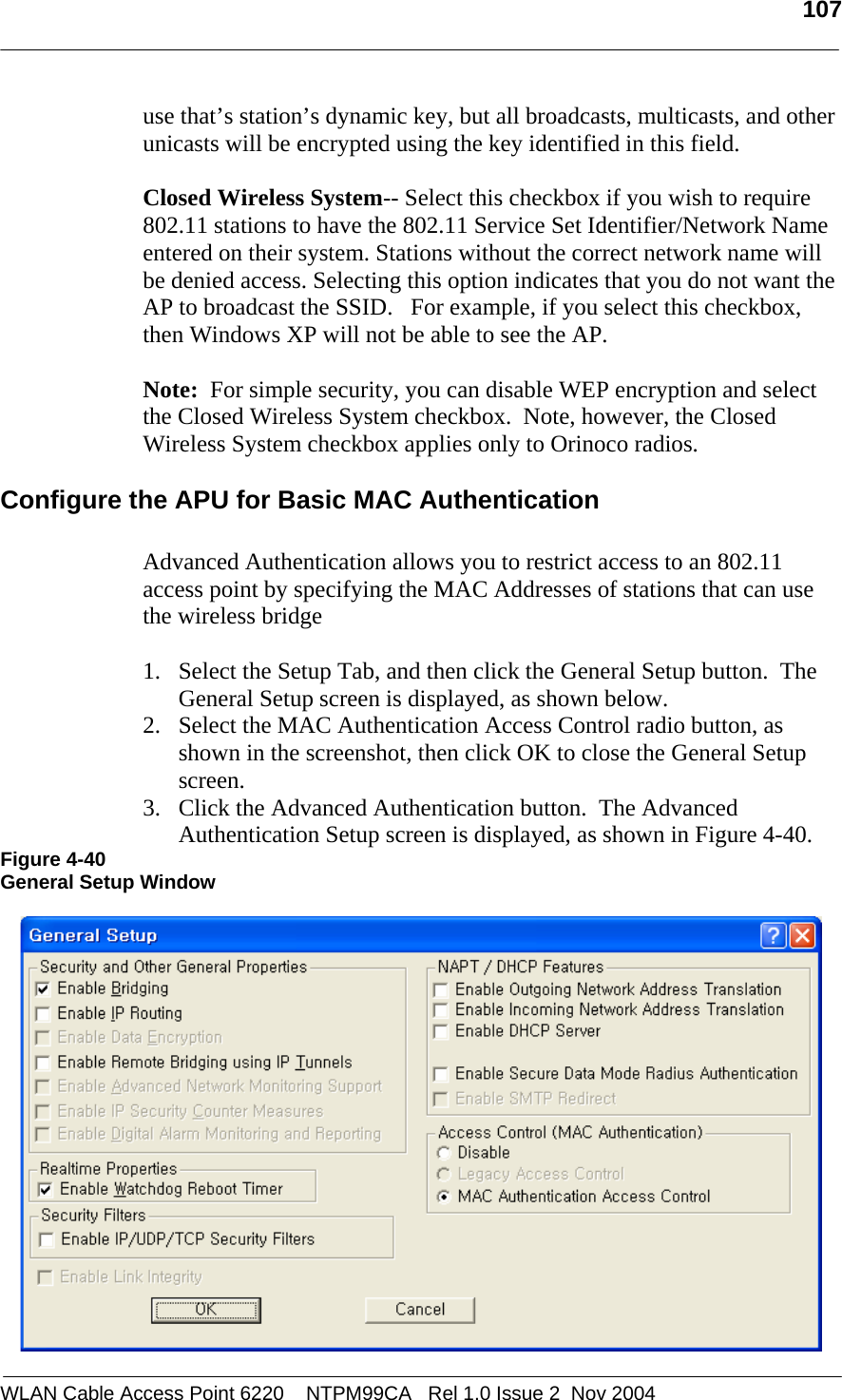
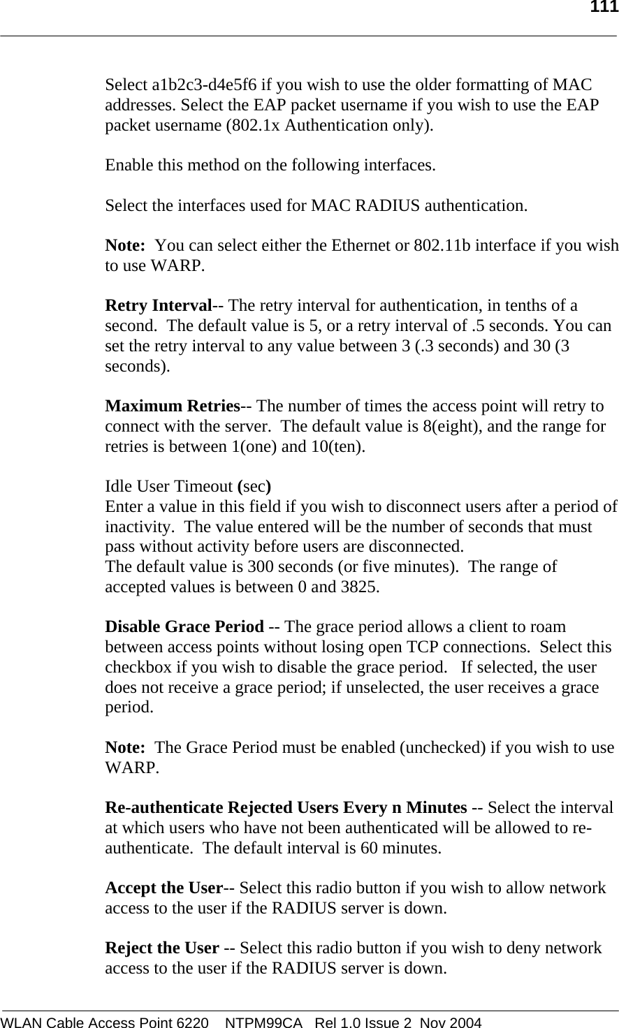
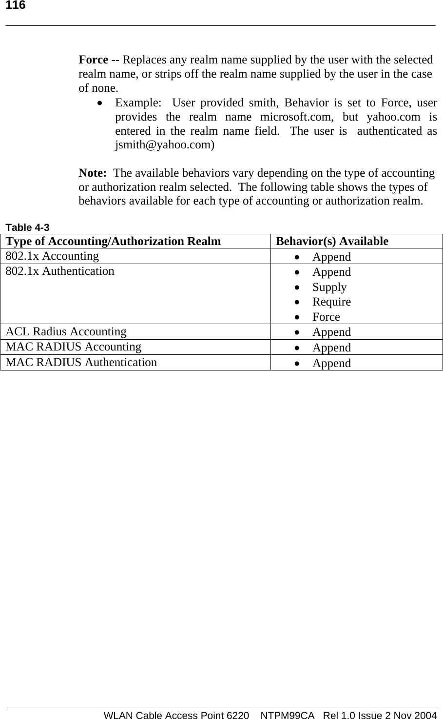
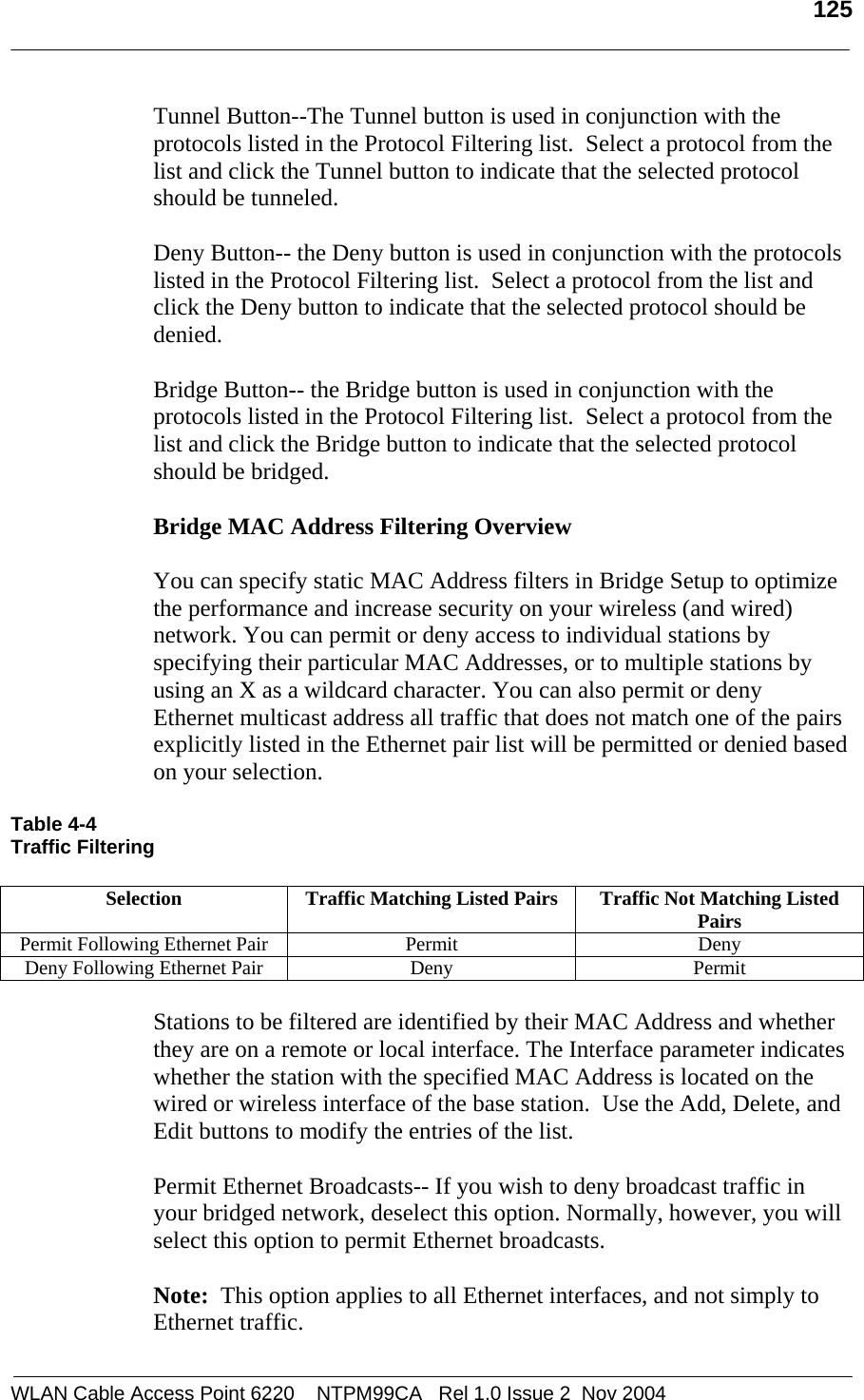
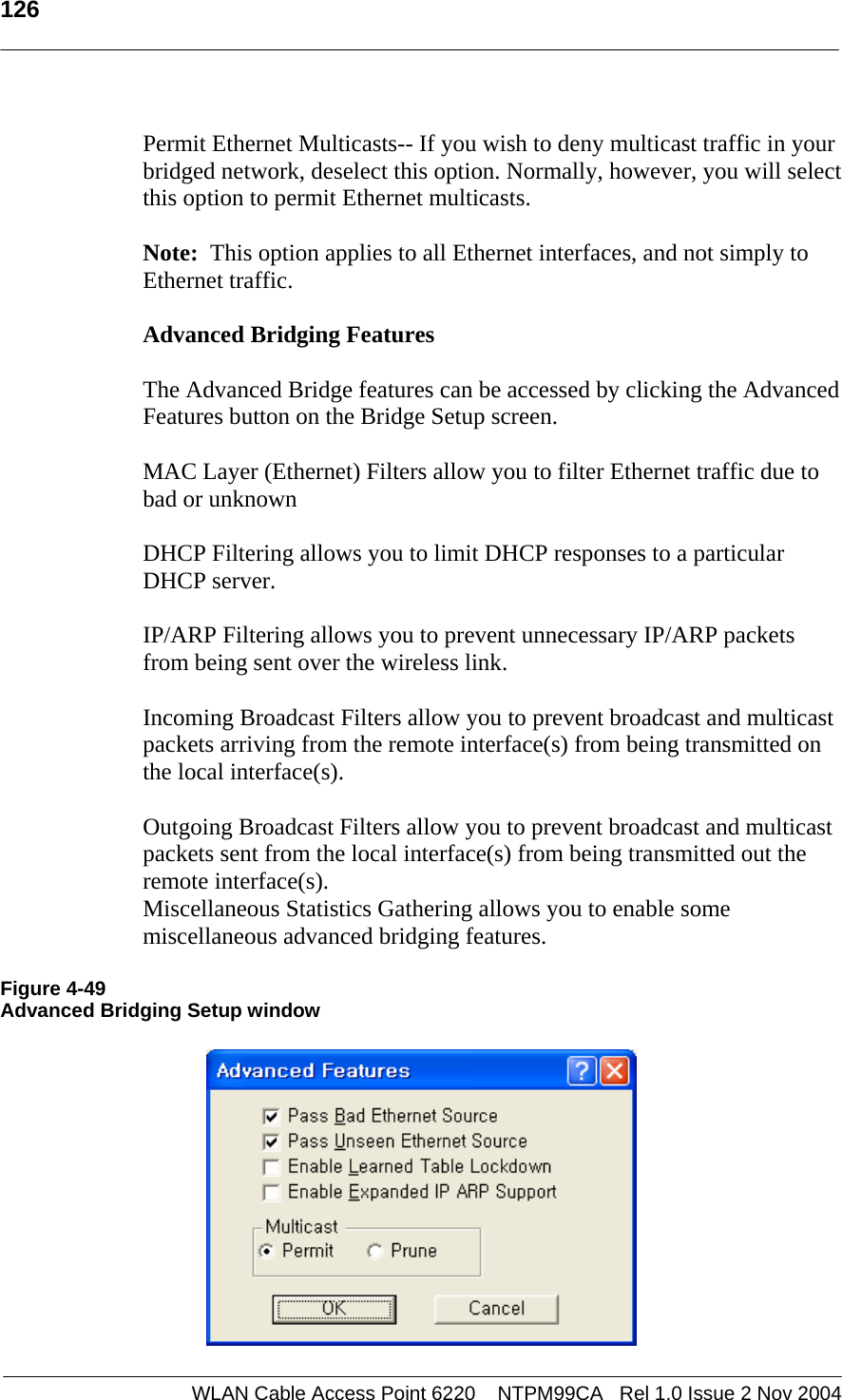
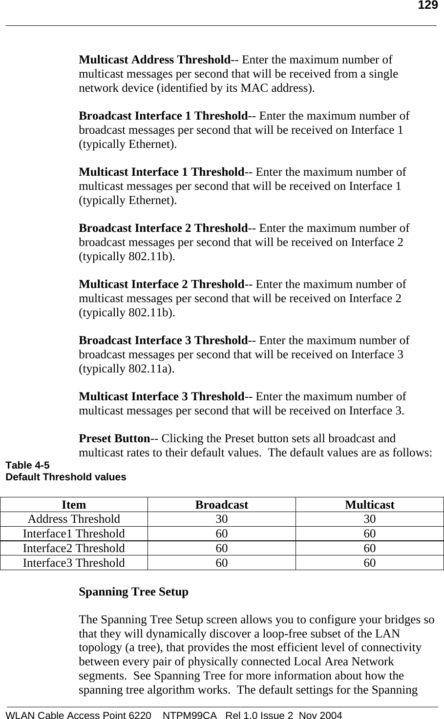
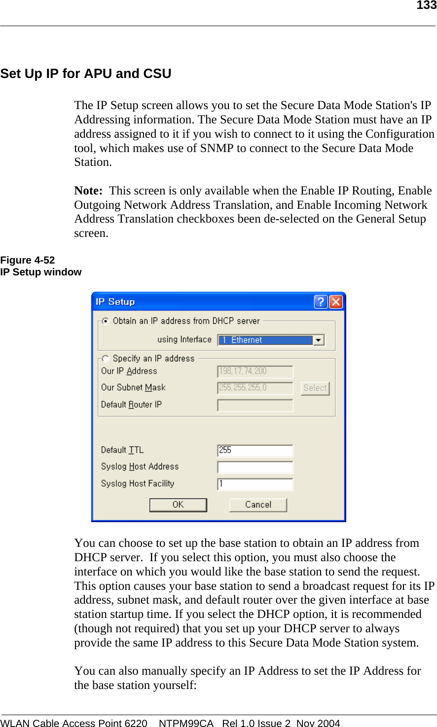
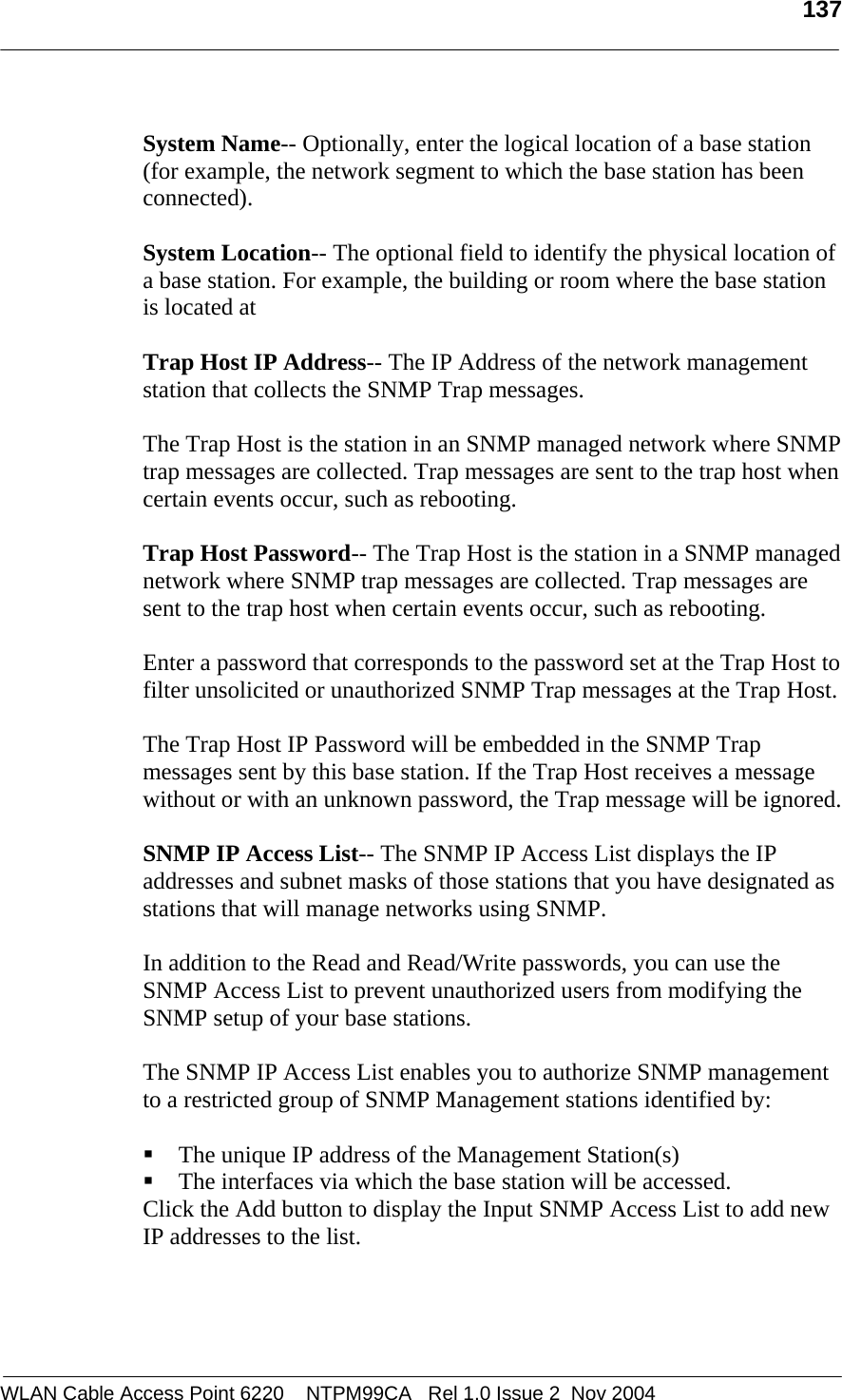
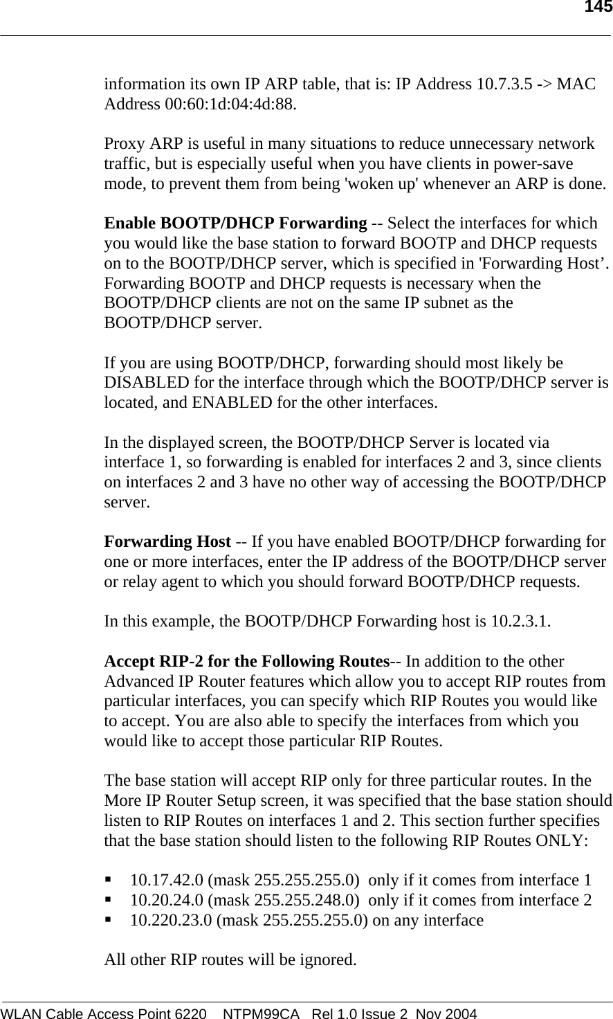
![206 WLAN Cable Access Point 6220 NTPM99CA Rel 1.0 Issue 2 Nov 2004 Appendix G. SNMP MIB List & Example values 1: [Loaded: RFC1213-MIB] sysDescr.0 (octet string) KarlBridge/Router v4.44-00-112900 SN-KNRG+a35CT3020551 V4.35 2: sysObjectID.0 (object identifier) kbridge-mib 3: sysUpTime.0 (timeticks) 6 days 00h:57m:11s.44th (52183144) 4: sysContact.0 (octet string) (zero-length) 5: sysName.0 (octet string) ABG-Proxim_ED 6: sysLocation.0 (octet string) (zero-length) 7: sysServices.0 (integer) 2 8: ifNumber.0 (integer) 2 9: ifIndex.1 (integer) 1 10: ifIndex.2 (integer) 2 11: ifDescr.1 (octet string) MACphyter Fast Ethernet 12: ifDescr.2 (octet string) AR5001-0000-0000 Wireless LAN Reference Card 13: ifType.1 (integer) ethernet-csmacd(6) 14: ifType.2 (integer) ethernet-csmacd(6) 15: ifMtu.1 (integer) 2042 16: ifMtu.2 (integer) 1522 17: ifSpeed.1 (gauge) 10000000 18: ifSpeed.2 (gauge) 54000000 19: ifPhysAddress.1 (octet string) 00.20.F6.04.03.A0 (hex) 20: ifPhysAddress.2 (octet string) 00.20.A6.4C.C7.51 (hex) 21: ifAdminStatus.1 (integer) up(1) 22: ifAdminStatus.2 (integer) up(1) 23: ifOperStatus.1 (integer) up(1) 24: ifOperStatus.2 (integer) up(1) 25: ifLastChange.1 (timeticks) 0 days 00h:00m:00s.00th (0) 26: ifLastChange.2 (timeticks) 0 days 00h:02m:00s.00th (12000) 27: ifInOctets.1 (counter) 1229704 28: ifInOctets.2 (counter) 86674413 29: ifInUcastPkts.1 (counter) 7078 30: ifInUcastPkts.2 (counter) 43463 31: ifInNUcastPkts.1 (counter) 4202 32: ifInNUcastPkts.2 (counter) 548012 33: ifInDiscards.1 (counter) 0 34: ifInDiscards.2 (counter) 41 35: ifInErrors.1 (counter) 0 36: ifInErrors.2 (counter) 2125 37: ifInUnknownProtos.1 (counter) 0 38: ifInUnknownProtos.2 (counter) 0 39: ifOutOctets.1 (counter) 8477301 40: ifOutOctets.2 (counter) 70108529 41: ifOutUcastPkts.1 (counter) 5799](https://usermanual.wiki/MTI/WCAP6220CSU.Users-Manual-Part-2/User-Guide-500120-Page-102.png)
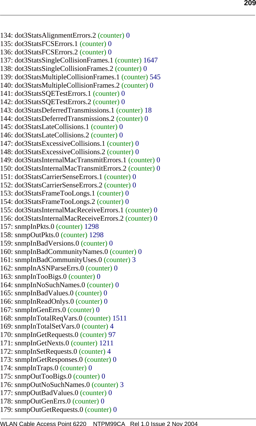
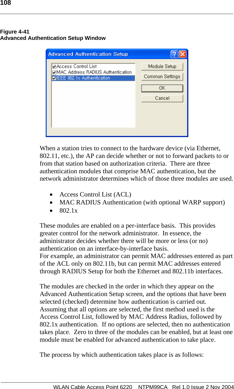
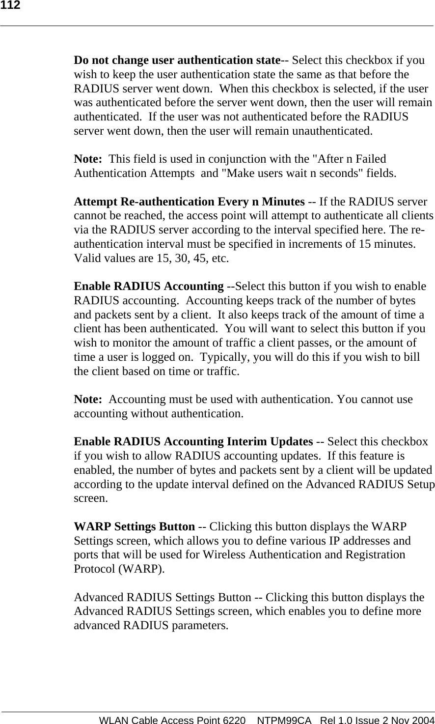
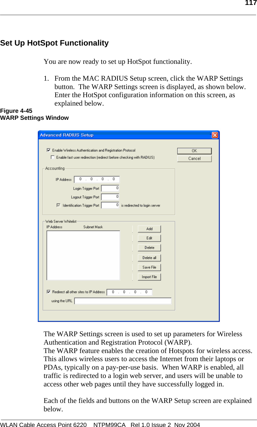
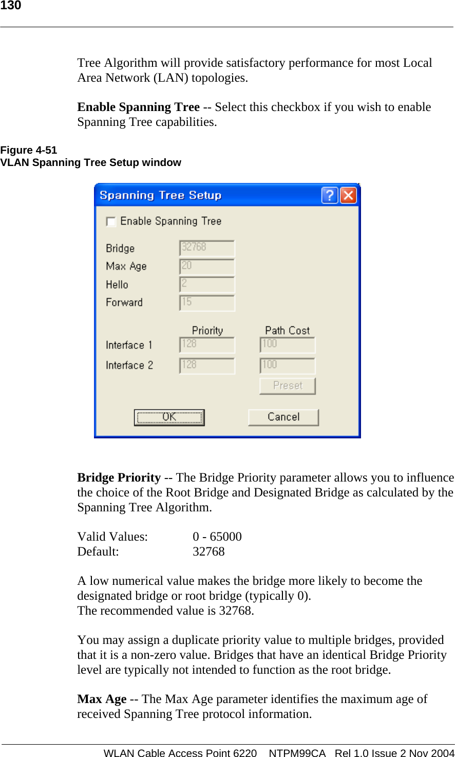
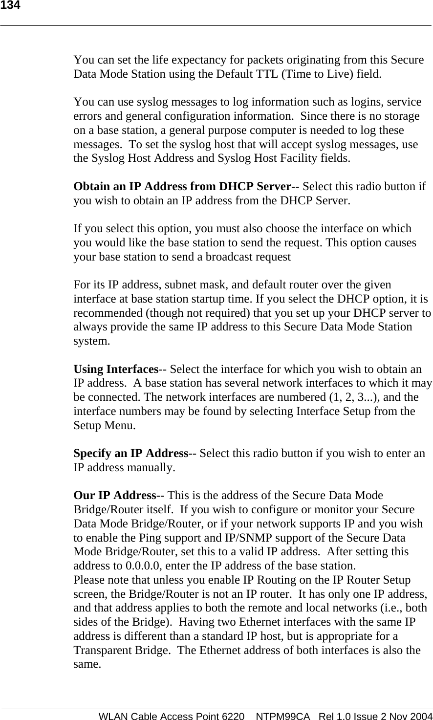
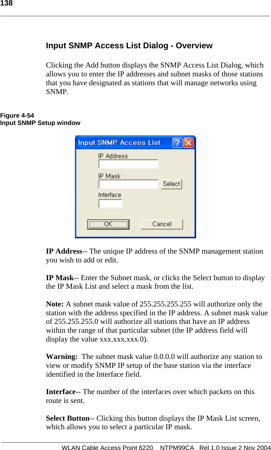
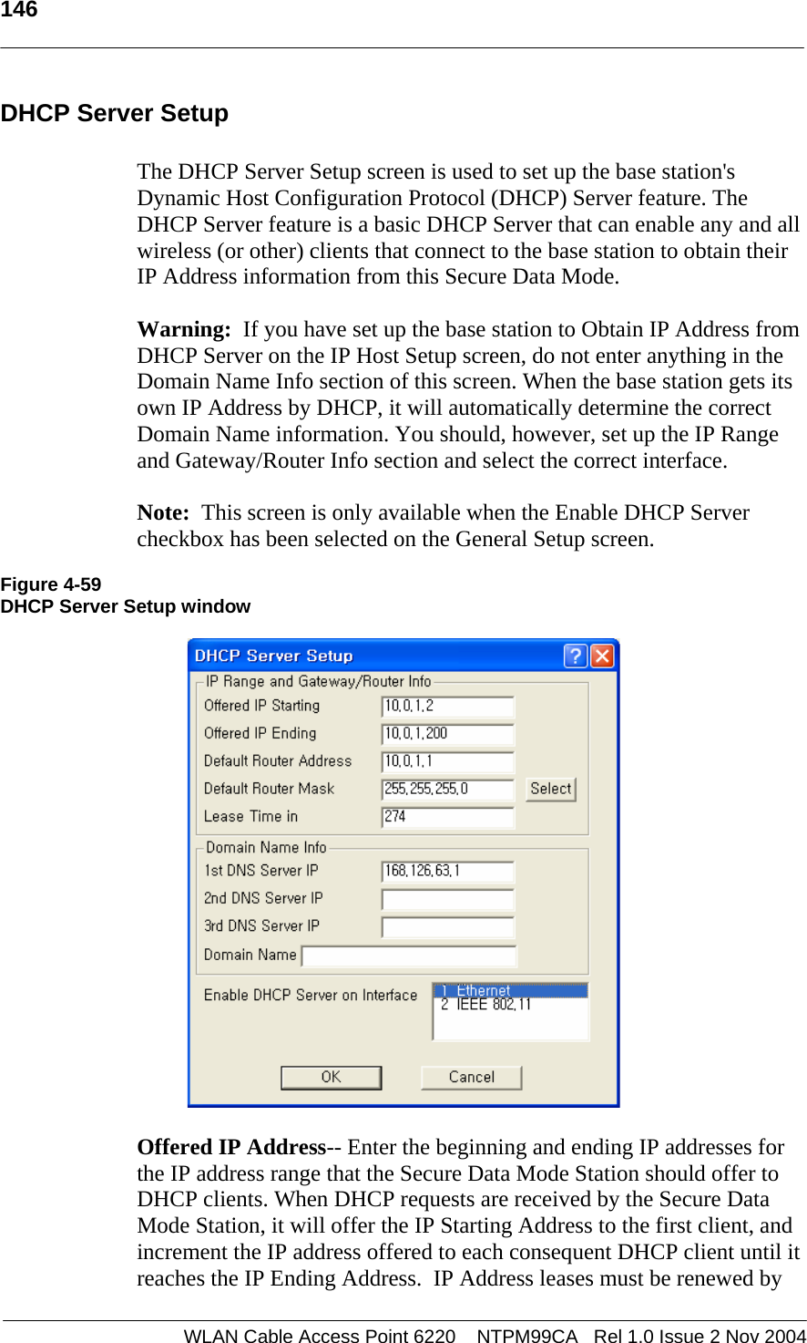
![207 WLAN Cable Access Point 6220 NTPM99CA Rel 1.0 Issue 2 Nov 2004 42: ifOutUcastPkts.2 (counter) 41946 43: ifOutNUcastPkts.1 (counter) 27181 44: ifOutNUcastPkts.2 (counter) 529297 45: ifOutDiscards.1 (counter) 0 46: ifOutDiscards.2 (counter) 1 47: ifOutErrors.1 (counter) 0 48: ifOutErrors.2 (counter) 0 49: ifOutQLen.1 (gauge) 0 50: ifOutQLen.2 (gauge) 0 51: [Loaded: EtherLike-MIB] ifSpecific.1 (object identifier) dot3 52: ifSpecific.2 (object identifier) iso.2.840.10036 53: ipForwarding.0 (integer) not-forwarding(2) 54: ipDefaultTTL.0 (integer) 255 55: ipInReceives.0 (counter) 52133 56: ipInHdrErrors.0 (counter) 0 57: ipInAddrErrors.0 (counter) 0 58: ipForwDatagrams.0 (counter) 0 59: ipInUnknownProtos.0 (counter) 0 60: ipInDiscards.0 (counter) 0 61: ipInDelivers.0 (counter) 34869 62: ipOutRequests.0 (counter) 34856 63: ipOutDiscards.0 (counter) 0 64: ipOutNoRoutes.0 (counter) 0 65: ipReasmTimeout.0 (integer) 0 66: ipReasmReqds.0 (counter) 0 67: ipReasmOKs.0 (counter) 0 68: ipReasmFails.0 (counter) 0 69: ipFragOKs.0 (counter) 0 70: ipFragFails.0 (counter) 0 71: ipFragCreates.0 (counter) 0 72: ipAdEntAddr.192.168.0.2 (ipaddress) 192.168.0.2 73: ipAdEntIfIndex.192.168.0.2 (integer) 1 74: ipAdEntNetMask.192.168.0.2 (ipaddress) 255.255.255.0 75: ipAdEntBcastAddr.192.168.0.2 (integer) 1 76: ipAdEntReasmMaxSize.192.168.0.2 (integer) 0 77: ipRouteDest.0.0.0.0 (ipaddress) 0.0.0.0 78: ipRouteIfIndex.0.0.0.0 (integer) 0 79: ipRouteMetric1.0.0.0.0 (integer) 1 80: ipRouteMetric2.0.0.0.0 (integer) -1 81: ipRouteMetric3.0.0.0.0 (integer) -1 82: ipRouteMetric4.0.0.0.0 (integer) -1 83: ipRouteNextHop.0.0.0.0 (ipaddress) 192.168.0.1 84: ipRouteType.0.0.0.0 (integer) indirect(4) 85: ipRouteProto.0.0.0.0 (integer) local(2) 86: ipRouteAge.0.0.0.0 (integer) 0 87: ipRouteMask.0.0.0.0 (ipaddress) 0.0.0.0](https://usermanual.wiki/MTI/WCAP6220CSU.Users-Manual-Part-2/User-Guide-500120-Page-103.png)