MTP Instruments MTP3100 Wireless Energy Monitor User Manual
MTP Instruments Inc. Wireless Energy Monitor Users Manual
Users Manual
1
User Manual
For Wireless Electricity Monitor MTP3001
Thank you for purchasing this smart wireless electricity monitoring system. This guide will help you to set u p
the wireless monitoring system quickly and easily.
What are in the standard package?
1) 1pc display unit
2) 1pc power adapter
3) 1pc power transmitter (including 2pcs C batteries)
4) 2pcs 18mm sensor clamp
5) 1pc 3m RJ45-USB data cable
6) 1pc Mini CD for software
7) White inner box
8) Customized Color Sleeve
9) 1pc user manual in English and French
If any parts are missing, please contact your seller immediately.
Before installation, please pay attention to following information:
1) Please read all instructions before you use the monitoring system
2) Please shake the Display Unit and the Power Transmitter first before installation. In case you hear any sound from inside of
the part, please don’t use it. Please replace it with your seller.
3) Do not allow children or people unfamiliar with these instructions to use your monitoring system.
4) Keep the monitor, transmitter and sensor clamp away from sources of heat, water or any other liquid.
5) Place the monitor, transmitter and sensor clamp where children can not touch or pull.
6) Don’t try to disassemble or modify any parts of the monitoring system. In case of problem, please consult your seller or
contact…..
7) Don’t use the monitoring system if you find your electric wire in abnormal conditions, such as loose wire, exposed copper
wire, burnt mark on wire insulation layer, holes on wire layer or damage on electric meter. In case of such abnormalities,
please consult a professional electrician immediately.
8) Periodically check all wires and components to ensure there is no damage.
9) Use a dry cloth to clean. Don’t use solvent, abrasive cleaners or water.
2
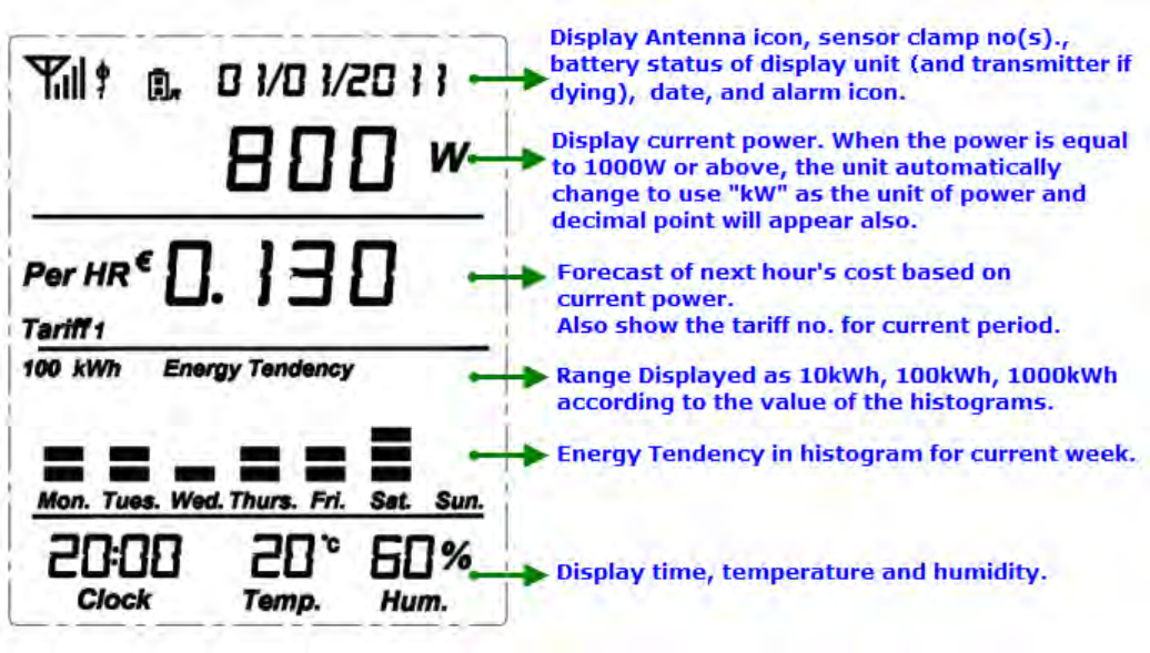
1. Default Display Under Normal Working Condition
Below display should be the display that the user usually sees from the LCD screen.
After pairing successfully, the LCD screen automatically returns to this display.
If there is no button operation, the LCD screen automatically returns to this display.
2. Resetting and Data Clearance
When the display unit is running under default display, press at the same time the SET/MODE key and the HISTORY key and
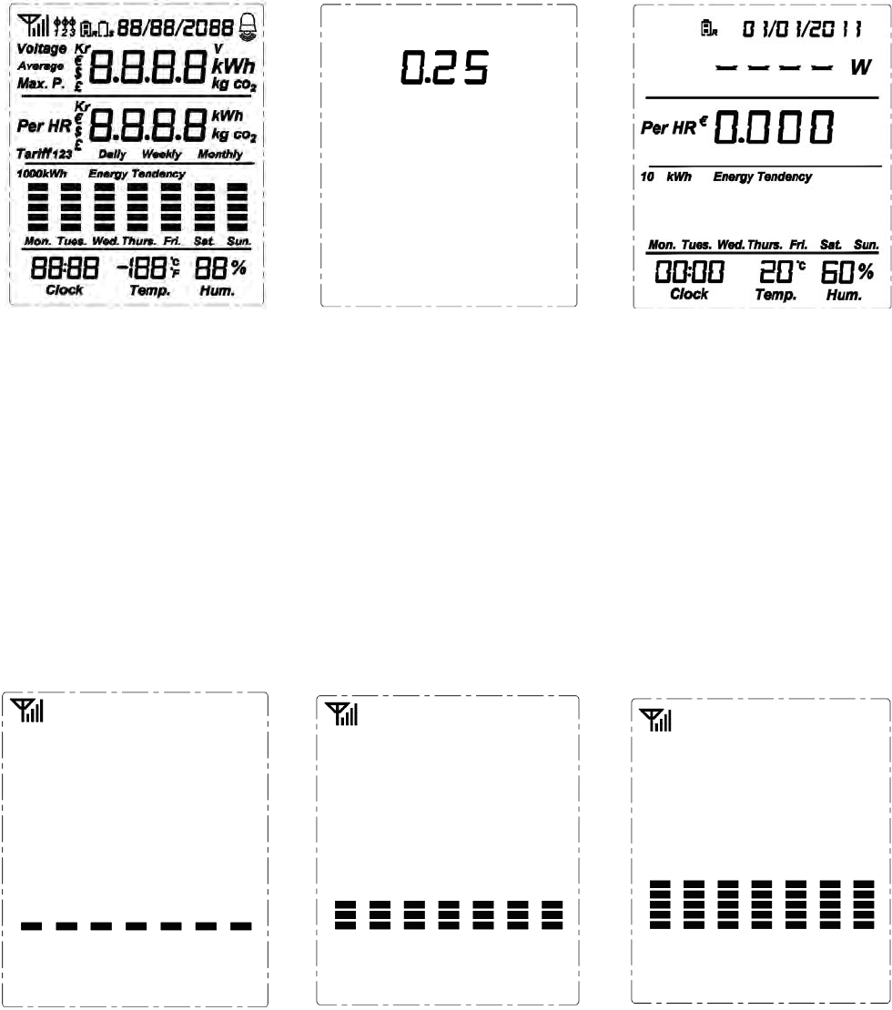
hold them there, the LCD full screen will appear for 3 seconds (as per Fig.1).
After that, the red LED light will flash twice. Now release the SET/MODE key and the HISTORY key. The LED light will keep
on and the LCD screen will show the programming version for 3 seconds (as per Fig.2).
Then the LED light goes off and the LCD screen resumes to default display under no signal condition (as per Fig.3). UP to
now all data in memory has been cleared.
Remarks: After data clearance, the date of the display will resume to the factory set date 01/01/2011 and time 00:00.
3
Fig.1 Fig.2 Fig.3
3. Signal Search
Keep the Transmitter as close to the Display Unit as possible. Pull out the clear plastic tab (marked with “REMOVE BEFORE
USING”) from the back of the transmitter. The tab is an insulation sheet, once it is pulled out, the built-in batteries will make
the transmitter start to work immediately and begin to send data to the Display Unit.
Now go back to the Display Unit, UPon default display under no signal condition (as per F ig.3), press the Linking key and
hold it for 3 seconds, the red LED light will flash twice and automatically enter into signal searching mode. Now release the
Linking key, the antenna icon will flash quickly at the left top corner and at the same time the histogram will increase grid by
grid in cycles (as per Fig.4, 5, 6) until it receives the signal from the transmitter.
Fig.4 Fig.5 Fig.6
Once the display unit receives the signal from the transmitter, the LCD screen will returns automatically to the default display
under normal working condition (as per Fig.7) and the antenna icon will stop flash and stay at the left top corner. At the
beginning, since there is very few electricity consumption, there is no histogram on the display screen.
In case the display unit failed in getting the signal from the transmitter in one minute, the LCD screen will return automatically
to the default display under no signal condition (as per Fig.3).
4
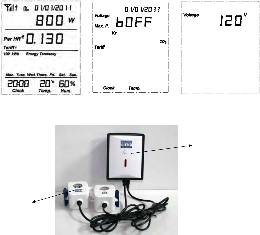
Fig.7 Fig.8 Fig.9
Installation of the 1-way Transmitter and the Sensor Clamp (as shown in below photo)
The transmitter already has a sensor clamp together with it.
You may choose to put the T ransmitter in a dry place near the m onitored object or stick the Transmitter on the wall near
the monitored object.
Fix the Sensor Clam p around the null line (also called zero lin e) or the live line of the m onitored object, just as below
photo is showing (Don’t fix the clamp around the ground wire). Make sure to let the line pass through the clamp.
Note: The sensor clamp in the standard package is with a diameter of 18mm
4. Display of Setting Mode and Settings
Display of Setting Mode
Upon default display under normal working condition (as per Fig.7), press the SET/MODE key and ho ld it for 5 seconds.
After the red LED light flashes twice, release the SET/MODE key. The LCD screen will enter into the display of setting mode
Transmitt
the Sensor
Clamp
5
(as per Fig.8).
First you see the symbol is flashing, ready for setting. Press the DOWN key to scroll to the desired item that needs to
be set. The sequence of flashing by pressing the DOWN key is: 1. (adjustable voltage)> 2. (currency)> 3.
(tariff)> 4. (CO2 calculating factor)> 5. (maximum power alarm value)> 6. (time)> 7.
(date)> 8. (temperature unit)> 9. (buzzer). Pressing the UP key will reverse the sequence.
During the setting, pressing the HISTORY key will save and exit the setting to return to the default display.
Voltage setting
The adjustable range for the voltage is 90-600V.
When you see the symbol is flashing, press the SET/MODE key to enter into the setting interface of voltage (as per
Fig.9). The default voltage value set in the factory is 12 0V. The value will start flash from the first digit “ 1”, press UP or
DOWN key to g et the correct number for the first digit (0-6), then press SET/MODE to c onfirm and fin d the second digit
flashing, now press U P or D OWN key to ge t the correct number for the s econd digit (0-9) a nd press SET /MODE key to
confirm and find the third digit flashing”, do the same to get the correct number for the last digit (0-9) and press SET/MODE
key to confirm and return to the Display of Setting Mode.
Currency setting
On the Display of Setting Mode, use the DOWN or UP key to scroll to and find it flashing. Press the SET/MODE key to
enter into the setting interface of voltage (as per Fig.10). Press the DOWN or UP key to select the desired currency and press
the SET/MODE key to confirm and return to the Display of Setting Mode.
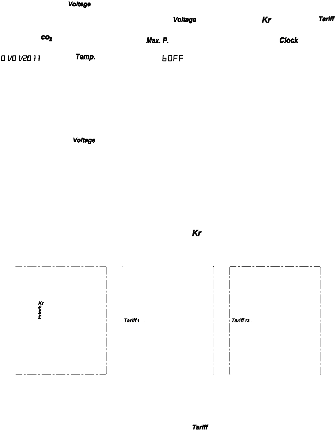
Fig.10 Fig.11 Fig.12
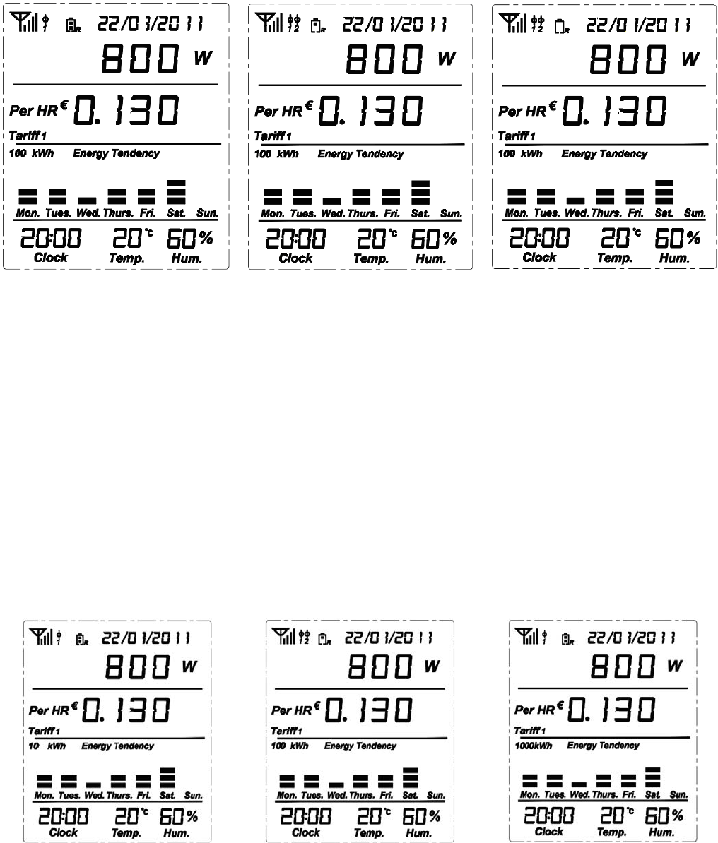
Tariff setting
On the Display of Setting Mode, use the DOWN or UP key to scroll to and find it flashing. Press the SET/MODE key
6
to enter into the setting interface of tariff (as per Fig.11).
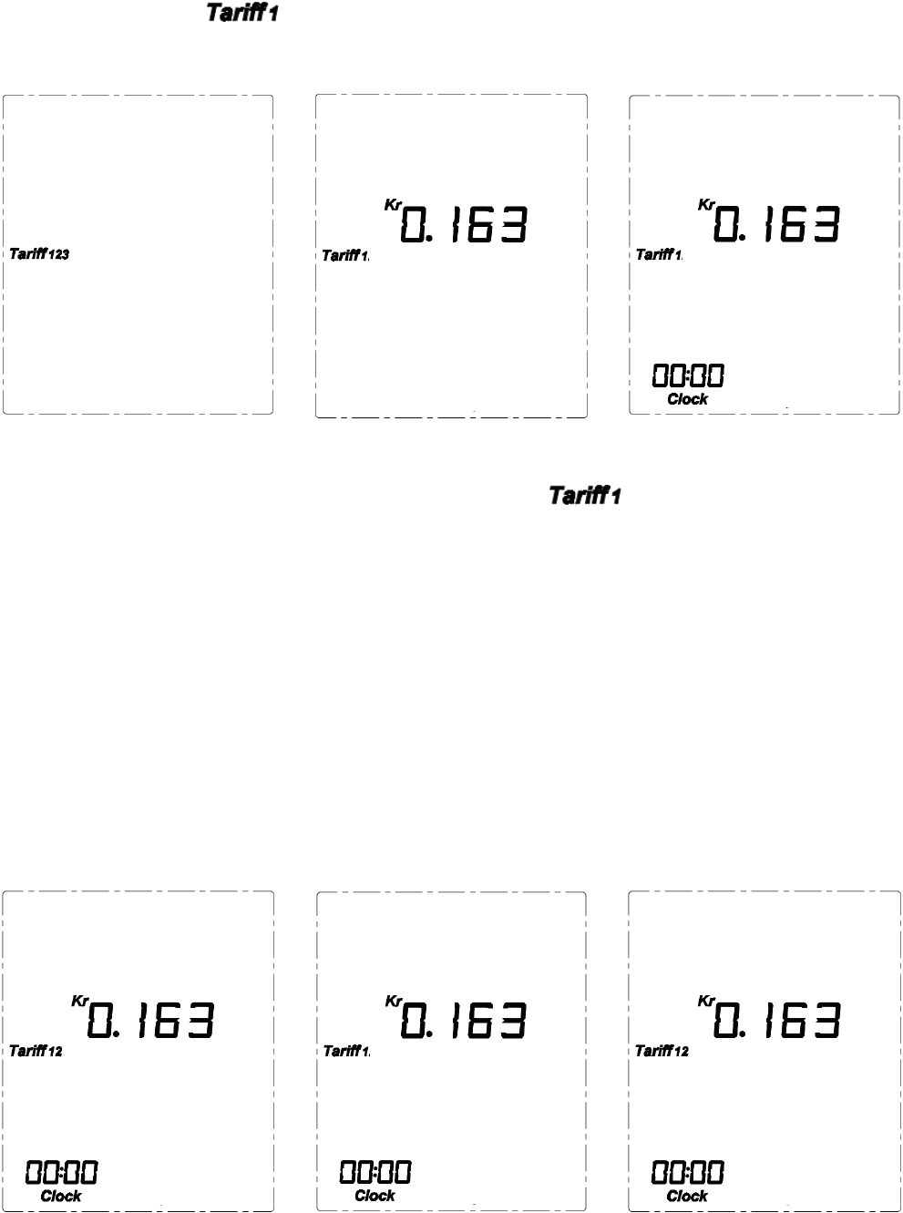
First you’ll see the digit “1” of is flashing, it means single tariff period for all day. Continuing to press the DOWN
key will lead to Tariff 12 (as per Fig.12, the flashing “2” stands for two tariff periods to be applied for a day) and Tariff 123 (as
per Fig.13, the flashing “3” stands for three tariff periods to be applied for a day).
Fig.13 Fig.14 Fig.15
To set for a single tariff, press the SET/MODE key when the digit “1” of is flashing and enter into the tariff value
setting interface (as per Fig.14). Use the UP or DOWN key to select the correct value (0-9) for each flashing digit and use the
SET/MODE key to confirm each digit. The pressing of SET/MODE key for the confirmation of the last digit will exit the tariff
setting and return to the Display of Setting Mode.
If there are two different tariffs for a day, press the SET/MODE key when the digit “2” of Tariff 12 is flashing and enter into
the tariff value and period setting interface (as per Fig.15). Use the UP or DOWN key to se lect the correct value (0-9) for each
flashing digit and use the SET/MODE key to confirm the digits. The pressing of SET/MODE key for the c onfirmation of the
last digit of the first tariff will lead to the flashing of clock value, use the UP or DOWN key to select the correct value of the
hour (00-23) and minute (00-59) for the starting time of the period for the first tariff and use the SET/MODE key to confirm
each value. The confirmation of the minute value will return to the tariff value setting for the second tariff (as per Fig.16).
Do the same thing to set the tariff value and starting time for the second tariff. The confirmation of the minute value will return
to the Display of Setting Mode.
Fig.16 Fig.17 Fig.18
7
If there are three different tariffs for a day, press the SET/MODE key when the digit “3” of Tariff 123 is flashing and enter
into the tariff value and period setting interface (as per Fig.17). Use the UP or DOWN key to select the correct value (0-9) for
each flashing digit and use the SET/MODE key to confirm the digits. The pressing of SET/MODE key for the confirmation of
the last digit of the first tariff will lead to the flashing of clock value, use the UP or DOWN key to select the correct value of the
hour (00-23) and minute (00-59) for the starting time of the period for the first tariff and use the SET/MODE key to confirm
each value. The confirmation of the minute value will return to the tariff value setting for the second tariff (as per Fig.18).
Do the same way to set the tariff value and starting time for the second tariff and the third tariff respectively. The confirmation
of the minute value of the start time for the third tariff will return to the Display of Setting Mode.
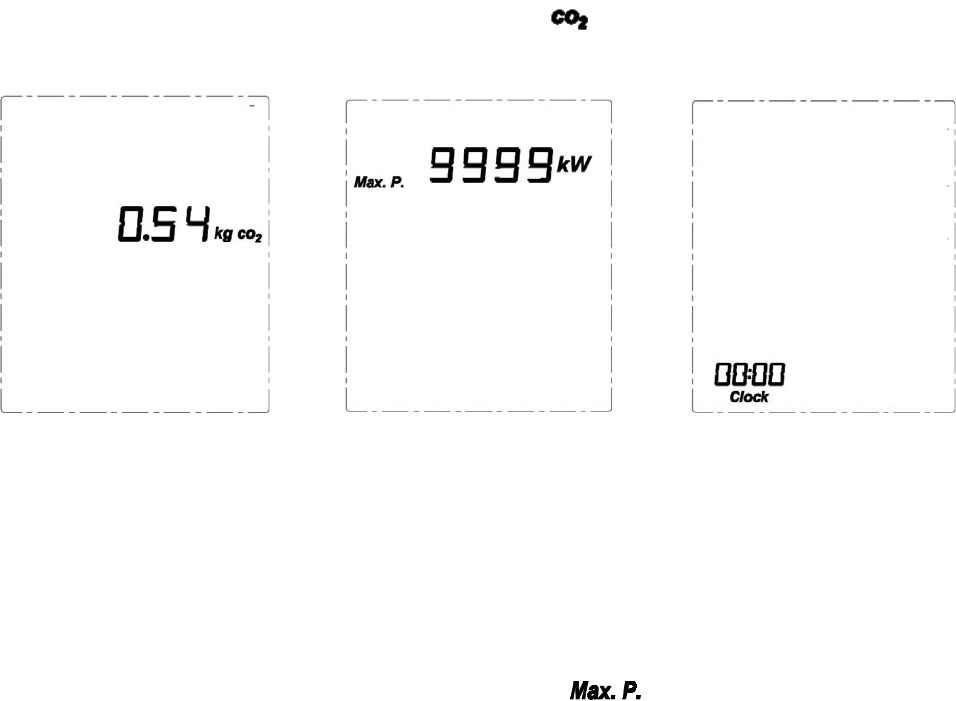
CO2 Calculating Factor Setting
On the Display of Setting Mode, use the DOWN or UP key to scroll to and find it flashing. Press the SET/MODE key to
enter into the setting interface of CO2 factor (as per Fig.19).
Fig.19 Fig.20 Fig.21
The default CO2 factor set in the factory is 0.54. The value will start flash from the first digit “0”, press UP or DOWN key to
get the correct number for the first digit ( 0-9), then press SET/MODE to confirm and find the second digit flashing, now press
UP or DOWN key to get the correct number for the second digit (0-9) and press SET/MODE key to confirm and find the third
digit flashing”, do the same to get the correct number for the last digit (0-9) and press SET/MODE key to confirm and return to
the Display of Setting Mode.
Maximum Power Alarm Value Setting
On the Display of Setting Mode, use the DOWN or UP key to scroll to and find it flashing. Press the SET/MODE
key to enter into the setting interface of Max.P. (as per Fig.20).
The default Max.P. value set in the factory is 9999kW. The value will start flash from the first di git “9”, press UP or DOWN
key to get the correct number for the first digit (0-9), then press SET/MODE key to confirm and find the second digit flashing,
now press UP or DOWN key to get the correct number for the second digit (0-9) and press SET/MODE key to confirm and find
the third digit flashing”, do the same to get the correct number for the last digit (0-9) and press SET/MODE key to confirm and
return to the Display of Setting Mode.
After the setting of Max.P., if the real power is larger than the Max.P. value, the LED light will flash once every 5 seconds. If
the buzzer is on, it will beep once every 15 seconds.
Time (Clock) Setting
8
On the Display of Setting Mode, use the DOWN or UP key to scroll to and find it flashing. Press the SET/MODE key
to enter into the setting interface of clock. (as per Fig.21).
The clock value will start flash from the hour value, press UP or DOWN key to get the correct number for the hour (00-23),
then press SE T/MODE key to c onfirm and fi nd the minute value flashing, now press UP or D OWN key to get the correct
number for the minute (00-59) and press SET/MODE key to confirm and return to the Display of Setting Mode.
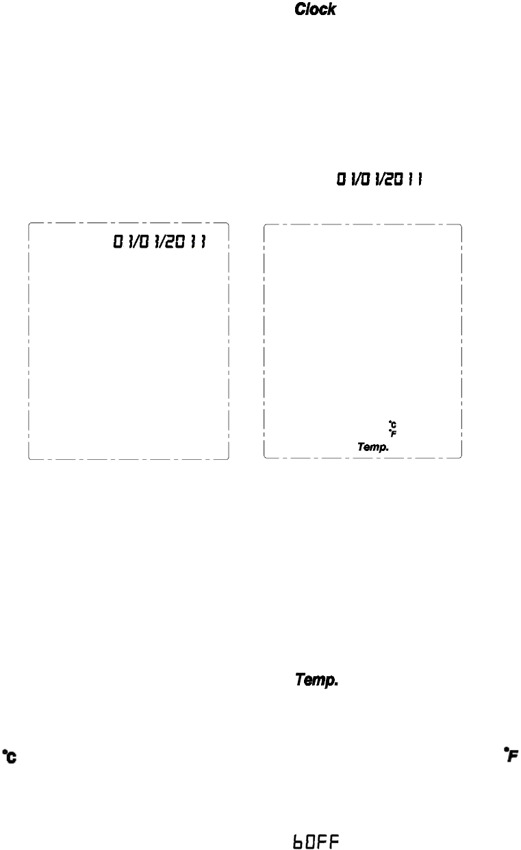
Date Setting
On the Display o f Setting Mod e, use the DOWN o r UP key to scroll to and find it f lashing. Press the
SET/MODE key to enter into the setting interface of date. (as per Fig.22).
Fig.22 Fig.23
The date value will start flashing from the year value, press UP or DOWN key to get the correct numbers for the last two digits
of the year value (0-9) and press SET/MODE key to confirm respectively. Then the month value will flash, press UP or DOWN
key to get the correct number for the month (01-12) and press SET/MODE key to confirm. Then the day value will flash, press
the UP or DOWN to select the correct number for the day (01-31) press the SET/MODE key to finish the date setting and return
to the Display of Setting Mode.
Temperature Unit Setting
On the Display of Setting Mode, use the DOWN or UP key to scroll to and find it flashing. Press the SET/MODE key
to enter into the setting interface of temperature unit setting. (as per Fig.23).
First it is the unit of flashing, use SET/MODE to confirm it or use the DOWN or UP key to switch to and confirm it.
The pressing of the SET/MODE key will finish the unit setting and return to the Display of Setting Mode.
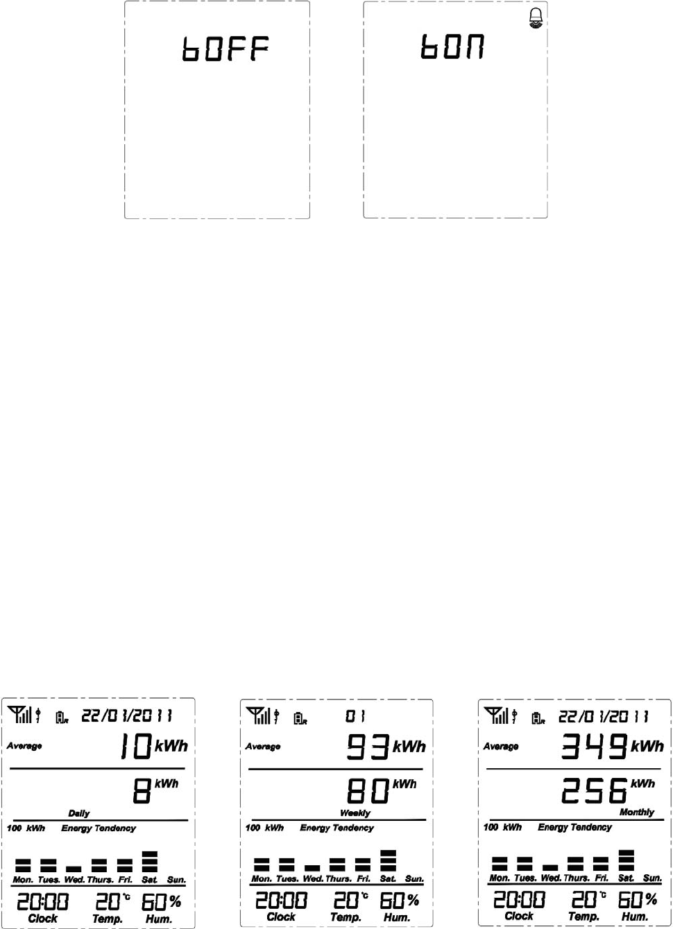
Buzzer ON/OFF
On the Display of Setting Mode, use the DOWN or UP key to scroll to and find it flashing. Press the SET/MODE key
to enter into the buzzer on/off switching interface (as per Fi g.24). Use the DOWN or UP key to switch between OFF and ON
status. When the buzzer is set ON, the bell icon will appear on the right top corner (as per Fig.25).
9
Fig.24 Fig.25
5. Viewing History Data and Average Data
When viewing the history data, if there is no button operation in 20 seconds, the display will return to default display under
normal working condition.
Up to now history data for present time frame
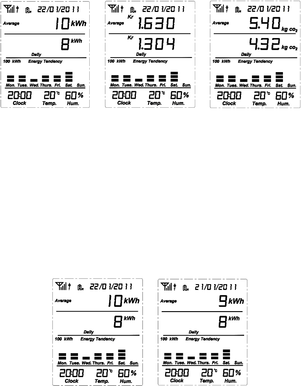
Upon default display under normal working condition (as per Fig.7), use the “HIST ORY” key t o switch the display in
sequence and cycle to the history displays of “Data up to now today” (indicated as Daily, as per Fig.26), “Data up to now this
Week” (indicated as Weekly, as per Fig. 27) and “Data up to now this month” (indicated as Monthly, as per Fig. 28).
“Data up to now today” means the accumulated data up to now from 00:00 of today.
“Data up to now this week” means the accumulated data up to now from 00:00 Monday of current week.
“Data up to now this month” means the accumulated data up to now from 00:00 the 1st of current month.
The average data is showed on the top of the “up to now history data”. This average data for up to now history data is a forecast
of the data for a com plete day, a complete week or a complete month based on the average data of smaller time frame. For
example, taking Fig.27 into consideration, the current week has an accumulated data of 80kWh in 6 days, so the daily average
kWh is 80/6, hence the forecast of the complete week should be 80/6*7=93kWh.
Fig.26 Fig.27 Fig.28
Switching of data type
10
Upon “Up to Now History Data” (as per Fig. 26, 27 and 28), press the SET/MODE key to switch the history data type among
energy consumption (kWh), Cost in currency (Kr) and CO2 emission (kg CO2) (as per Fig.29, 30 and 31)
Fig.29 Fig.30 Fig.31
Viewing history data and average data of past time frame
View the history data of the last 7 days.
Upon default display under normal working condition (as per Fig.7), use the “HISTORY” key to switch to “Data up to now
today” (indicated as Daily, as per Fig.26).
Now press the UP key once to view the history data of yesterday. Press the UP key twice to view the history data of the day
before yesterday, and etc. You can press the UP key 7 times to view the history data of 7 days ago.
The date on the display will change to be in accordance with the history data date.
The average data displayed on each past day is calculated by = (Today’s Average Data + All Past Days’ Real Data)/Number of
days (including today).
“All Past Days” means from yesterday down to the history day under viewing (example as per Fig.32 and 33)
Fig.32 Fig.33
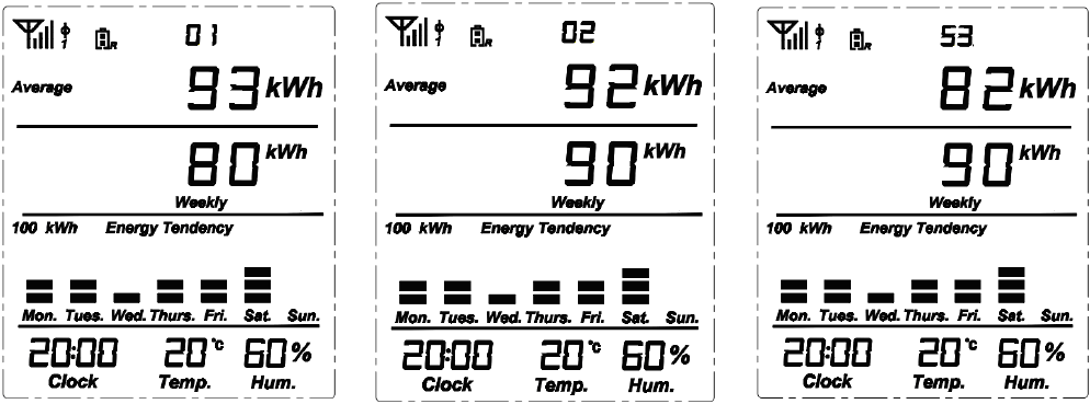
Viewing the history data of the last 52 weeks
11
Upon default display under normal working condition (as per Fig.7), use the “HISTORY” key to switch to “Data up to now
this week” (indicated as Weekly, as per Fig.27).
Now press the UP key once to view the history data of last week. Press the UP key twice to view the history data of the week
before last week, and etc. You can press the UP key 52 times to view the history data of 52 weeks ago.
The date on the display will change to be the number in ac cordance with the history data wee k. 01 stands for this week, 02
stands for last week, and so on.
The average data displayed on ea ch past week is calculated by = (This W eek’s Average Data + Al l Past Weeks’ Real
Data)/Number of Weeks (including this week).
“All Past Weeks” means from last week down to the history week under viewing (example as per Fig.34, 35 and 36)
Fig.34 Fig.35 Fig.36
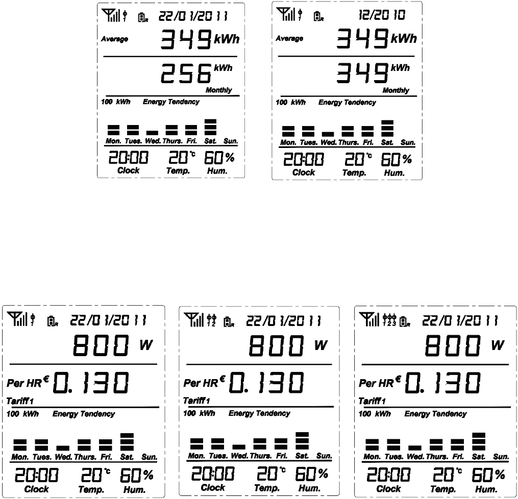
Viewing the history data of the last 24 months
Upon default display under normal working condition (as per Fig.7), use the “HISTORY” key to switch to “Data up to now
this month” (indicated as Monthly, as per Fig.28).
Now press the UP key once to view the history data of last month. Press the UP key twice to view the history data of the month
before last month, and so on. You can press the UP key 24 times to view the history data of 24 months ago.
The date on the display will change to display the month and year in accordance with the history data.
The average data displayed on each past month is calculated by = (This Month’s Average Data + A ll Past Months’ Real
Data)/Number of Months (including this month).
“All Past Months” means from last month down to the history month under viewing (example as per Fig.37 and 38)
12
Fig.37 Fig.38
6. Antenna Icon and Sensor Clamp Icon on the Display
When the Display Unit re ceives signal from the trans mitter, the antenna icon will appear and stay on t he left corner of t he
screen. The Sensor clamp icon besides the antenna icon will indicate how many sensor clamps are connected (as per Fig. 39, 40
and 41)
Fig.39 Fig.40 Fig.41
7. Battery Status
1) The battery icon with R stands for the battery for the display unit (because the display unit is a data receiver). When the
total remaining batteries is over 3.9v, the icon displays as fu ll. For remaining batteries between 3.1V and 3.9V, the icon
displays as half full. For remaining batteries under 3.1V, the icon displays as blank (as per Fig.42, 43 and 44)
13
Fig.39 Fig.40 Fig.41
2) The battery icon with S stands for the battery for the transmitter (because the transmitter is a data sender). Only when the
total remaining batteries is below 2.3V, the warning icon will appear and rem ind the user to replace the batteries. The
battery icon with S will flash once every second (as per Fig. 47)
8. Backlight
When the display unit is connected with external power supply via the power adapter, the backlight is available whenever there
is a key operation.
When the display unit is only powered by the batteries, the backlight is available only from 18:00-24:00 when there is a key
operation.
9. Histogram
Fig.42 Fig.43 Fig.44
The histogram is used to indicate the energy consumption tendency. Each histogram can have up to five grids.
If the highest histogram is equal to or below 10kWh, the full scale of the histogram is displayed as 10kWh. That means each
grid will stand for a value of 2kWh (10/5=2kWh) (as per Fig.42).
If the highest histogram is between 10kWh and 100kWh, the full scale of the histogram is displayed as 100kWh. That means
14
each grid will stand for a value of 20kWh (as per Fig. 43).
If the highest histogram is higher than 100kWh, the full scale of the histogram is displayed as 1000kWh. That means each grid
will stand for a value of 200kWh (as per Fig.44).
The grid appears when its real value is more than 1/3 of its value.
10. Transmitter Signal Frequency Setting
Use a slim stick to push the setting hole on the transmitter and hold there for 3 seconds, the LED light will change its color
among red light, yellow light, and green light.
Choose red light for the frequency of 10s, yellow light for 15s and green light for 20s.
After setting, the LED light will always flash in the selected color.
11. FCC STATEMENT
1. This device complies with Part 15 of the FCC Rules.
Operation is subject to the following two conditions:
(1) This device may not cause harmful interference, and
(2) This device must accept any interference received, including interference that may cause undesired operation.
2. Changes or modifications not expressly approved by the party responsible for compliance could void the user’s authority to
operate the equipment.
12. IC STATEMENT
- English: "
1. This device complies with Industry Canada licence-exempt RSS standard(s).
Operation is subject to the following two conditions:
(1) this device may not cause interference, and
(2) this device must accept any interference, including interference that may cause undesired operation of the
device."
2. Changes or modifications not expressly approved by the party responsible for compliance could void the user’s authority to
operate the equipment.
- French:"
Le présent appareil est conforme aux CNR d'Industrie Canada applicables aux appareils radio
exempts de licence. L'exploitation est autorisée aux deux conditions suivantes : (1) l'appareil ne
doit pas produire de brouillage, et (2) l'utilisateur de l'appareil doit accepter tout brouillage
radioélectrique subi, même si le brouillage est susceptible d'en compromettre le fonctionnement."