MTRLC MG7550 16x4 DOCSIS 3.0 Cable Modem plus AC1900 Router User Manual
MTRLC LLC 16x4 DOCSIS 3.0 Cable Modem plus AC1900 Router
UserManual.wiki
>
MTRLC
>
MG7550 User Manual
>
User Manual.PDF
Contents
1.
User Manual.PDF
2.
User Manual
User Manual.PDF
Navigation menu
Upload a User Manual
Namespaces
Wiki Guide
HTML
PDF
Info
Views
User Manual
Discussion / Help
Navigation
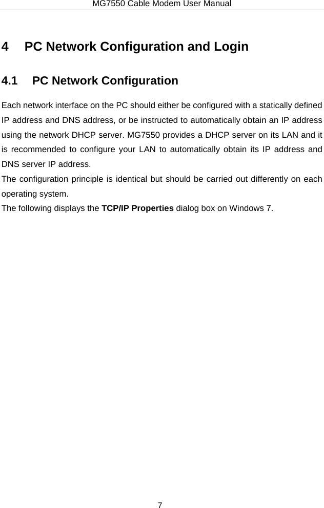
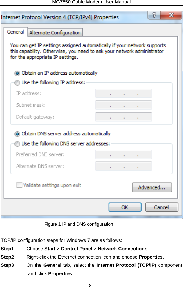
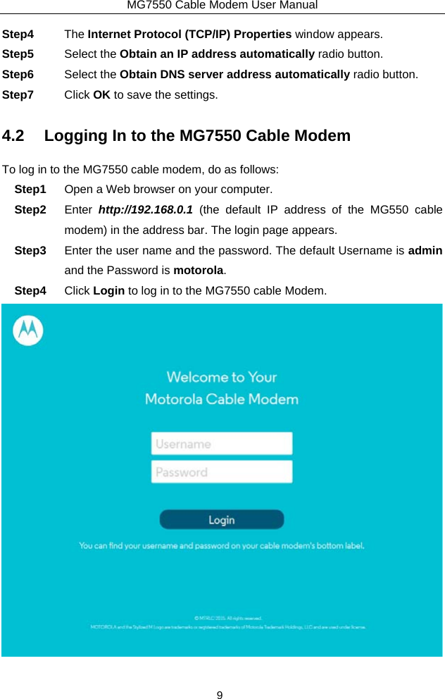
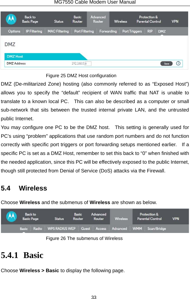
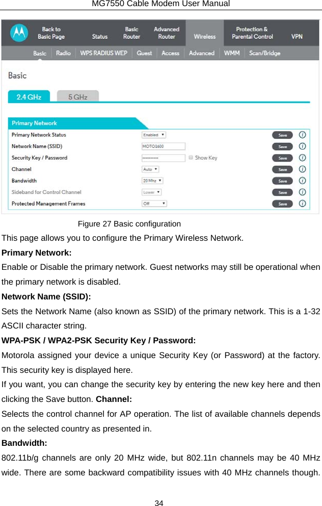
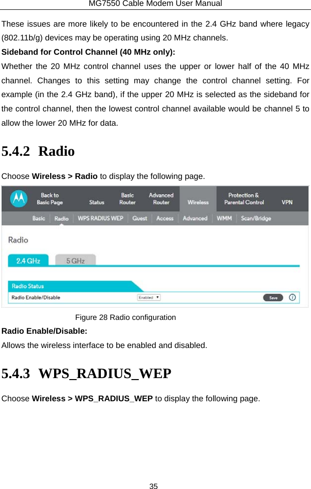
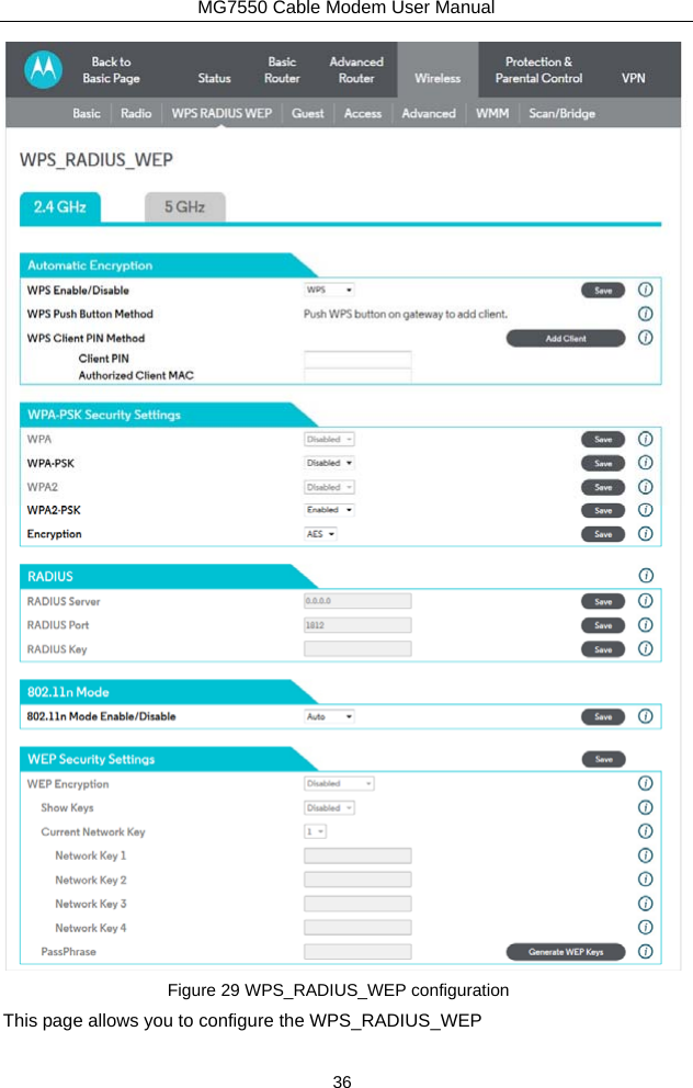
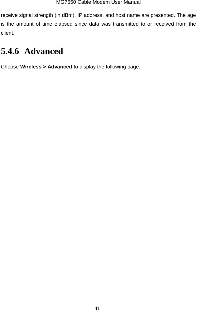
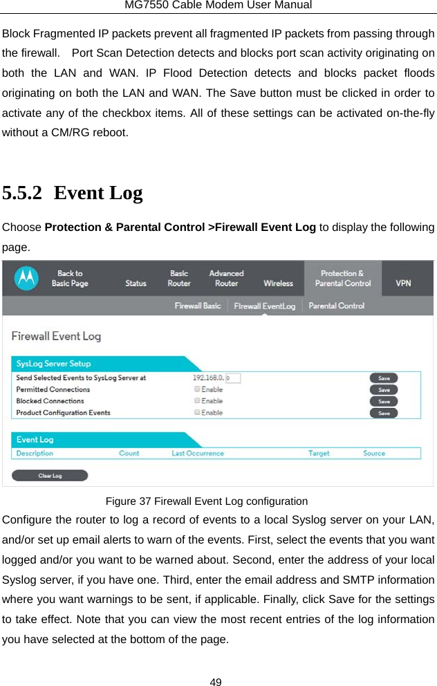
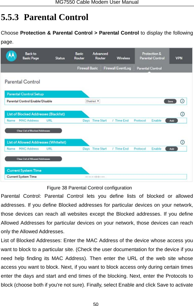
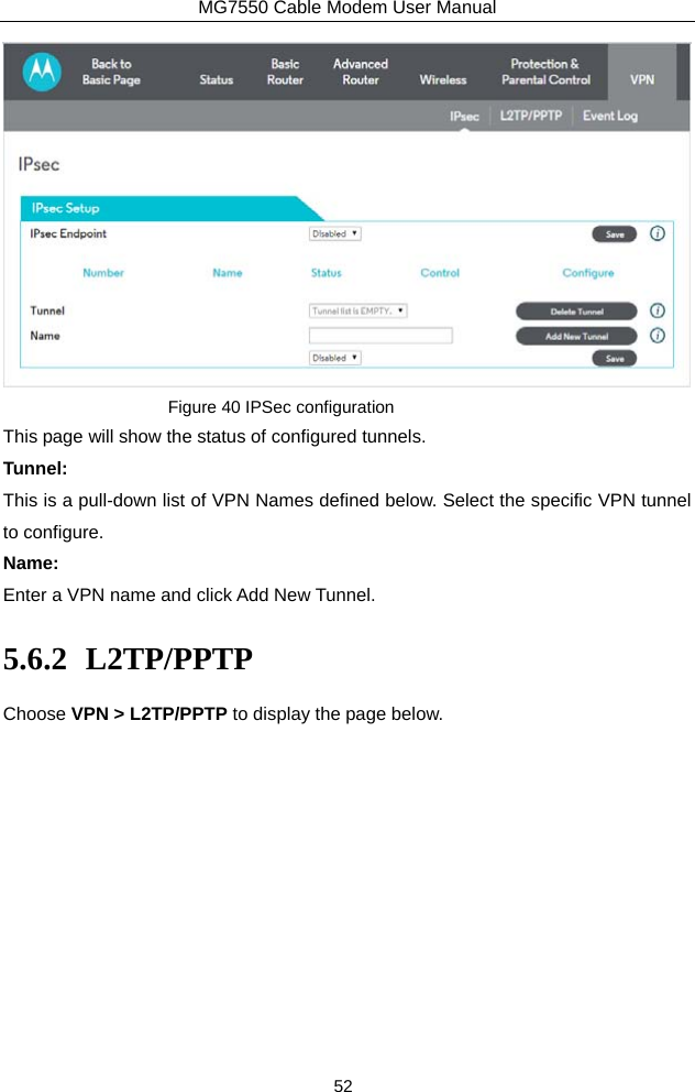
![MG7550 Cable Modem User Manual 32 7223#term mon The CMTS is now configured to accept RIPv2 messages. If the CM/RG is registered on the CMTS, you should see messages that are similar to the message below: 00:28:41: RIP: received packet with MD5 authentication 00:28:41: RIP: received v2 update from 10.24.81.148 on Cable2/0 00:28:41: 10.24.81.0/24 via 10.24.81.148 in 1 hops The CM/RG has broadcast that is connected to the network 10.24.81.0/24 through the interface 10.24.81.148. This information is not very useful to the CMTS because it already knows that the network 10.24.81.0/24 is connected directly to one of its interfaces (Cable2/0). It ignores this message and doesn’t add any information to the IP routing table. Here is the IP routing table after the CMTS has received RIPv2 messages: 7223#sh ip route Codes: C - connected, S - static, I - IGRP, R - RIP, M - mobile, B - BGP D - EIGRP, EX - EIGRP external, O - OSPF, IA - OSPF inter area N1 - OSPF NSSA external type 1, N2 - OSPF NSSA external type 2 E1 - OSPF external type 1, E2 - OSPF external type 2, E - EGP i - IS-IS, L1 - IS-IS level-1, L2 - IS-IS level-2, ia - IS-IS inter area * - candidate default, U - per-user static route, o - ODR P - periodic downloaded static route Gateway of last resort is 10.24.95.17 to network 0.0.0.0 10.0.0.0/8 is variably subnetted, 3 subnets, 2 masks C 10.24.80.0/24 is directly connected, Cable2/0 C 10.24.81.0/24 is directly connected, Cable2/0 C 10.24.95.16/28 is directly connected, FastEthernet0/0 S* 0.0.0.0/0 [1/0] via 10.24.95.17 In the example above, the CM/RG was set up to send RIPv2 messages to the CMTS. The CMTS was also set up to receive these messages. 5.3.8 DMZ Host Choose Advanced Router > DMZ Host to display the following page.](https://usermanual.wiki/MTRLC/MG7550.User-Manual-PDF/User-Guide-2974626-Page-35.png)