MTeye Security SIW35-SIGL-01 BLUETOOTH COMMUNICATION MODULE User Manual Bluetooth rev1 0
MTeye Security Ltd BLUETOOTH COMMUNICATION MODULE Bluetooth rev1 0
USERS MANUAL
Security LTD
User manual
Bluetooth wireless technology is a short-range radio technology. Bluetooth wireless
technology makes it possible to transmit signals over short distances between
telephones, computers and other devices and thereby simplify communication and
synchronization between devices. It is a global standard that eliminates wires and
cables between both stationary and mobile devices.
Bluetooth radio uses a fast acknowledgement and frequency-hopping scheme to make
the link robust, even in noisy radio environments.
1.Scope
The module Bluetooth RF is a version 1.0 Class 1 high power level with integrates
RF and Base–Bend controller in small package.
2. Definition for type of module.
The architecture in this module is class 1 with 39 pads to integration in another smart
module by MTEYE.
The module Bluetooth it’s being supported the HCI communication and power supply
from two batteries.
The output signal RF its matching to 50 ohms direct to the mother board antennas
This pad it’s the only signal RF that its supplier from the RF module Bluetooth.
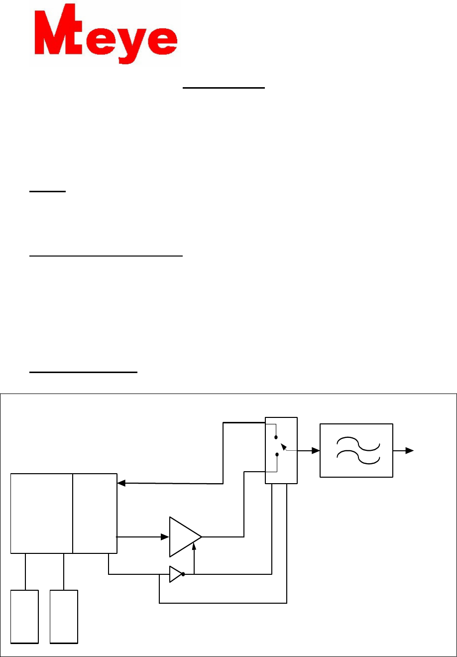
3.BLOCK DIAGRAM
Figure1: block diagram
PA
BPF FILTER
2.45GHz+/-50MHz
SiW
3500
MODULE RF
2.4GHz
Bluetooth
MICROPROCESSOR
BLUETOOTH
V1
V2
RX
TX- OUT
SPDT SWITCH
PA2423L
32.000
MHz
32.768
KHz
TX RX SWITCH

11 Hamelacha St.
Afek Industrial Park
Rosh Ha’ayin 48091
ISRAEL
eye
eyeeye
eye Security LTD
4. SPECIFICATION
OPERATING RATING4.1
SUPPLY VOLTAGE = 3.6 V MAX [supply from mother board]
INTERNAL REGULATION = 1.85 VDD
TEMPERATURE RANGE = -35c TO 75c
ABSOLUTE RATING4.2
SUPPLY VOLTAGE = 3.63 V MAX [supply from mother board]
1.8 V MINIMUM
TEMPERATURE RANGE = -55c TO 125c
RF INPUT SIGNAL (TO RX MODE) = +5dBm
5. GENERAL PARAMETER
NO ITEMS SPECIFICATION
1 DEEP SLEEP CURRENT
CONSUMPTION
24µA
2 CARRIER FREQUENCY 2.402 MHz to 2.480MHz
3 Modulation method GFSK ,1 Mbps , 0.5BT GAUSSIAN
4 Maximum Date Rate 732 Kbit/sec
5 Output power +18 dBm max
6 RF input/output impedance 50 Ω
7 Base band crystal OSC 32.000 MHz
8 Host interface UART
9 Hopping Frequency 2402to 2480 MHz
f= 2402+k MHz . k=0, 1, 2, 3 ….78
10 Receiver Sensitivity -80dBm
11 Current at max output power
82 mA
11 Hamelacha St.
Afek Industrial Park
Rosh Ha’ayin 48091
ISRAEL
eye
eyeeye
eye Security LTD
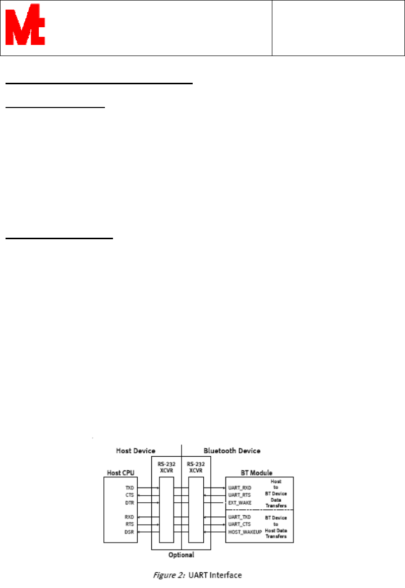
INTERFACE DESCRIPTION. 6
6.1 UART Interface.
This reference design includes an interface compliant
With the HCI UART Transport Layer (Part H4) and 3-Wire UART Transport Layer
(Part H5).
The firmware auto-detects between H4 and H5 UART, providing a simple mechanism
For communicating with other digital devices using the
RS-232 standard.
6.2 Hardware Signals.
Four signals are used to implement the UART interface, With two optional signals
Available for Enhanced power management features. UART_RXD and UART_TXD
transfer Data between the host and SiW3500. UART_CTS and UART_RTS can be
used to implement RS-232 hardware flow control. EXT_WAKE and
HOST_WAKEUP are used to Controls sleep functions of the SiW3500 and host,
Respectively. All UART connections are implemented using CMOS technology with
Signal levels of 0 V and VDD_P.
The RS-232 port on a standard PC is also a UART interface. These RS-232 ports use
different voltage levels to represent "high" (3 V) and "low" (-3 V). To interface the
SiW3500 UART port to a PC’s serial port or other RS-232 device, it is necessary to
Use an RS-232 transceiver to translate between the I/O levels available from the
SiW3500 and the RS-232 levels available from a PC or other such device.
Note: In order to communicate with the UART at high data rates
(Typically above 115 Kbaud) using a standard PC, A high-speed serial port adapter
card is typically required for the PC

11 Hamelacha St.
Afek Industrial Park
Rosh Ha’ayin 48091
ISRAEL
eye
eyeeye
eye Security LTD
7. Module Bluetooth Pads
Number
pad
Symbol I/0 Description
1 D_GND GND
GND
2 AUX_UART_TXD Output. Auxiliary UART serial port output.
3 PCM_CLK CMOS bi-directional
PCM synchronous data clock
4 PCM_SYNC CMOS bi-directional
PCM synchronization data strobe
5 PCM_IN CMOS bi-directional
PCM data output from SiW3500.
6 PCM_OUT CMOS bi-directional
PCM data input to SiW3500.
7 EXT_WAKE CMOS input
Wake up signal from host.
8 UART_RTS CMOS output
UART flow control ready to send.
9 UART_CTS CMOS input UART flow control clear to send.
10 UART_TXD CMOS output
UART transmit data.
11 UART_RXD CMOS input UART receive data.
12 D_GND GND
GND
13 VANLG IN V_ANA 3.6
14 ADC_IN Analog
Analog to digital converter input
15 VANLG Power
Positive supply to internal analog voltage
regulator.
16 MFP_0 CMOS bi-directional
Multi-function I/O port.
17 VCC_OUT
Power
Regulated output from internal analog voltage
regulator.
18 MFP_1 CMOS bi-directional
Multi-function I/O port.
19 VDIG IN V_DIG 3.6
20 MFP_2 CMOS bi-directional
Multi-function I/O port.
21 VDD_C OUT VDD 1.8 V
22 MFP_3 CMOS bi-directional
Multi-function I/O port.

11 Hamelacha St.
Afek Industrial Park
Rosh Ha’ayin 48091
ISRAEL
eye
eyeeye
eye Security LTD
7. Module Bluetooth Pads [ con]
23 VDD_P OUT VDD 1.8 to External memory
24 MFP_4 CMOS bi-directional
Multi-function I/O port.
25 A_GND GND
Ground connections
26 TX_RX_OUTPUT OUT RF SIGNAL
27 A_GND GND
GND
28 VDD _ALT OUT VDD 1.8 to External UART
29 MFP_5 CMOS bi-directional
Multi-function I/O port.
30 MFP_6 CMOS bi-directional
Multi-function I/O port.
31 TX_RX_SWITCH OUT TX\RX SWITCH
32 PWR_REG1_EN CMOS bi-directional
CLOCK_REQ_OUT control line for external
TCXO
33 D_GND GND
Ground connections
34 D_GND GND
Ground connections
35 RESET IN System level reset
36 SCL CMOS output
I²C CLOCK
37 SDA CMOS bi-directional
I²C DATA
38 WP CMOS output
Write enable for external memory
39 CLK_32MHz Analog
System clock crystal
11 Hamelacha St.
Afek Industrial Park
Rosh Ha’ayin 48091
ISRAEL
eye
eyeeye
eye Security LTD
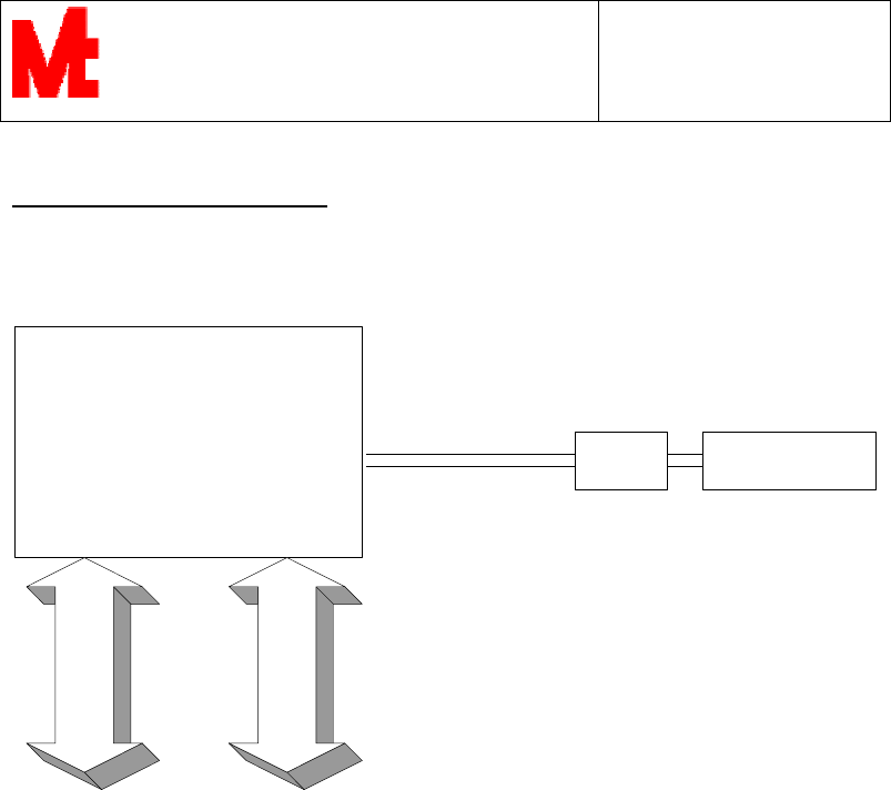
8. Sample for PCB placement
Bluetooth Module
MT-SiW35-SiGeL-01
Metching
Network
Chip Antenna
SMT
Microstrip line zl=50ohm
UART
MFP
11 Hamelacha St.
Afek Industrial Park
Rosh Ha’ayin 48091
ISRAEL
eye
eyeeye
eye Security LTD
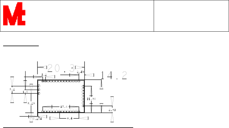
9. Dimension

11 Hamelacha St.
Afek Industrial Park
Rosh Ha’ayin 48091
ISRAEL
eye
eyeeye
eye Security LTD
10."FCC STATEMENT
FCC STATEMENTFCC STATEMENT
FCC STATEMENT
This equipment has been tested and found to comply with the limits for a Class B
digital device, pursuant to Part 15 of the FCC rules. These limits are designed to
provide reasonable protection against harmful interference in a residential installation.
This equipment generates uses and can radiate radio frequency energy and, if not
installed and used in accordance with the instructions, may cause harmful interference
to radio communications. However, there is no guarantee that interference will not
occur in a particular installation. If this equipment does cause harmful interference to
radio or television reception, which can be determined by turning the equipment off
and on, the user is encouraged to try to correct the interference by one or more of the
following measures:
a) Reorient or relocate the receiving antenna.
b) Increase the separation between the equipment and receiver.
c) Connect the equipment to an outlet on a circuit different from that to which
the receiver is connected.
d) Consult the dealer or an experienced radio/TV technician.
This device complies with Part 15 of the FCC Rules.
Operation is subject to the following two conditions:
a) This device may not cause harmful interference
b) This device must accept any interference received, including interference
that may cause undesired operation.
11.FCC Warning
Modifications not expressly approved by the manufacturer could void the user
authority to operate the equipment under FCC Rules.
Instructions concerning human exposure to radio frequency electromagnetic
fields.
To comply with FCC Section1.307 (b)(1) for human exposure to radio frequency
electromagnetic fields, implement the following instruction: A distance of at least
30 cm between the equipment and all persons should be maintained during operation
of the equipment."