MW McWong WCM-01 BLE Module User Manual
MW McWong International Inc BLE Module Users Manual
Users Manual

©2015McWongInternationalInc.//1921ArenaBlvd,Sacramento,CA95834//(916)371‐8080//McWongInc.com
Bluetooth®SmartModule
Datasheet
Pacwave™Bluetooth®Smart(BLE)Module
FEATURES
BuiltinCSRμEnergy®CSR1010
Bluetooth®Smart(v4.1)chipset
+7.5dBmMaximumRFTransmit
OutputPower
‐92.5dBmRFReceiveSensitivity
RSSIMonitoring
Built‐inSwitch‐modePowerSupply
512Kbit(65,536x8)EEPROM
Real‐TimeClock(RTC)andCalendar
UARTCommunication
Wake‐upInterrupt
GPIO
Operatingvoltage:3.3V
~16mAActiveTransmit/Receive
~1mAIdleMode
<5uASleepMode
Size:24mmx28.5mm
U.FLConnector
Bluetooth®SmartSpecificationv4.2
Ready
FCCandBluetooth®SIGPending
RoHSCompliant
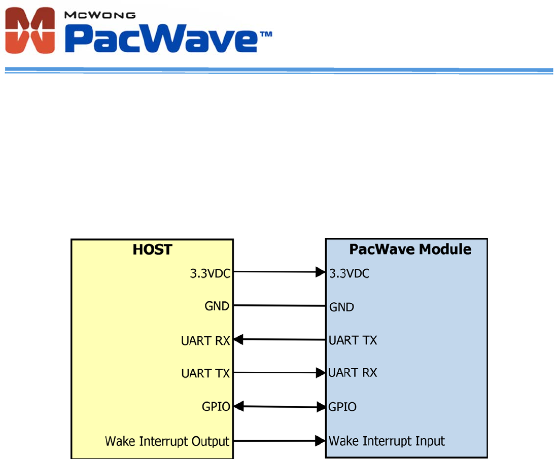
DESCRIPTION
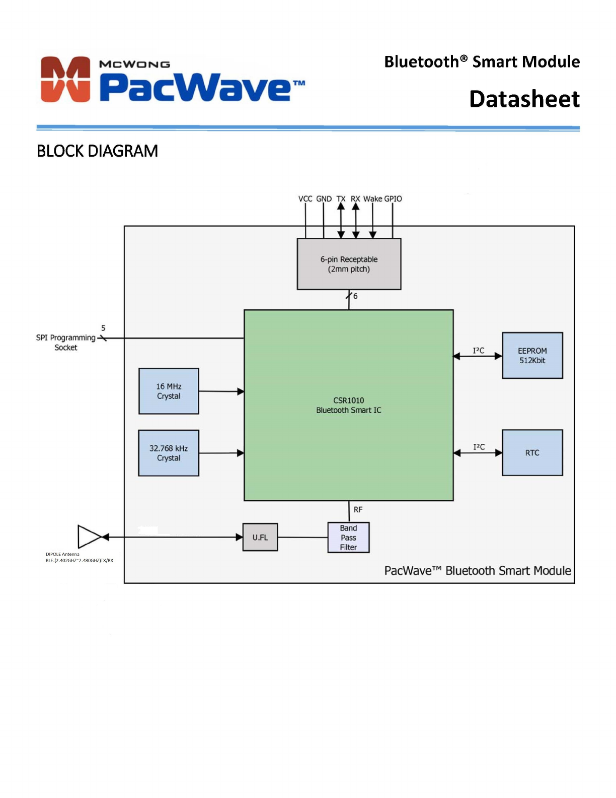
ThePacWave™Bluetooth®Smartmodule
fullysupportssingle‐modeBluetoothLow
Energyoperation.Themodulereceivesits
powerfromahostthatprovides3.3Vand
groundtothe6‐pinreceptacle,andalso
communicateswiththehostviatheUART
onthesame6‐pinreceptacle.Thetwo
additionalpinsprovideawake‐upinterrupt
inputandageneralpurposeinput/output
(GPIO).Themodulecanbeprogrammed
usingtheopensockets.TheRTCcanbe
usedfortimekeepingandschedulingof
activities.
Bluetooth®SmartModule
Datasheet
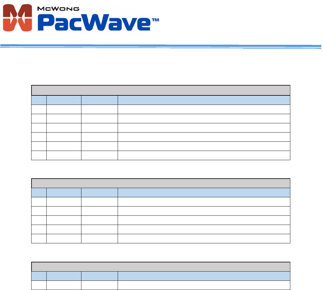
PINDESCRIPTIONS
J1(6‐pinReceptacle)
PinNameI/OTypeDescription
1VDDInputPowersupplytomodule
2GNDGNDPowersupplyGround
3RXInputUARTInterfaceReceive
4TXOutputUARTInterfaceTransmit
5GPIOI/OGeneralPurposeInput/output
6WAKEInputModulewake‐upinterruptsignal
J2(Programming/Debugsocket)
PinNameI/OTypeDescription
1SCLKI/OProgramming/DebugSPIclock
2CSInputProgramming/DebugSPIchipselect
3MOSIInputProgramming/DebugSPIMOSI
4MISOOutputProgramming/DebugSPIMISO
5SPI_ENInputProgramming/DebugSPIEnable
J3(Off‐moduleAntennaConnector)
PinNameI/OTypeDescription
1Ext.Ant.I/OU.FL(male)Off‐moduleantennaconnector
Bluetooth®SmartModule
Datasheet
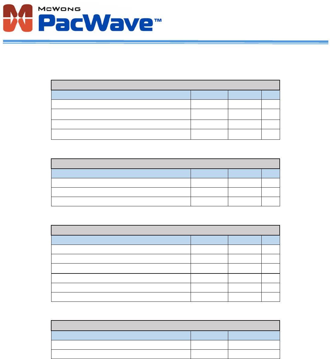
ELECTRICALSPECIFICATIONS
AbsoluteMaximumRatings
RatingMinMaxUnit
Inputsupplyvoltage1.84.4V
I/Osupplyvoltage‐0.44.4V
OtherterminalvoltagesVSS‐0.4VCC+0.4V
StorageTemperature‐4085°C
RecommendedOperatingConditions
RatingMinMaxUnit
Inputsupplyvoltage1.83.6V
I/Osupplyvoltage1.23.6V
Operatingtemperaturerange‐3085°C
DigitalTerminals
VoltageLevelsMinMaxUnit
Voltageinputlogiclevellow‐0.40.3xVCCV
Voltageinputlogiclevelhigh0.7xVCCVCC+0.4V
Inputrise/falltime‐25ns
Voltageoutputlogiclevellow‐0.4V
Voltageoutputlogiclevelhigh0.75xVCC‐ V
Outputrise/falltime‐5ns
ESDProtection
ConditionClassMaxRating
Humanbodymodelcontactdischarge22000V(allpins)
ChargeddevicemodelcontactdischargeIII500V(allpins)
Bluetooth®SmartModule
Datasheet
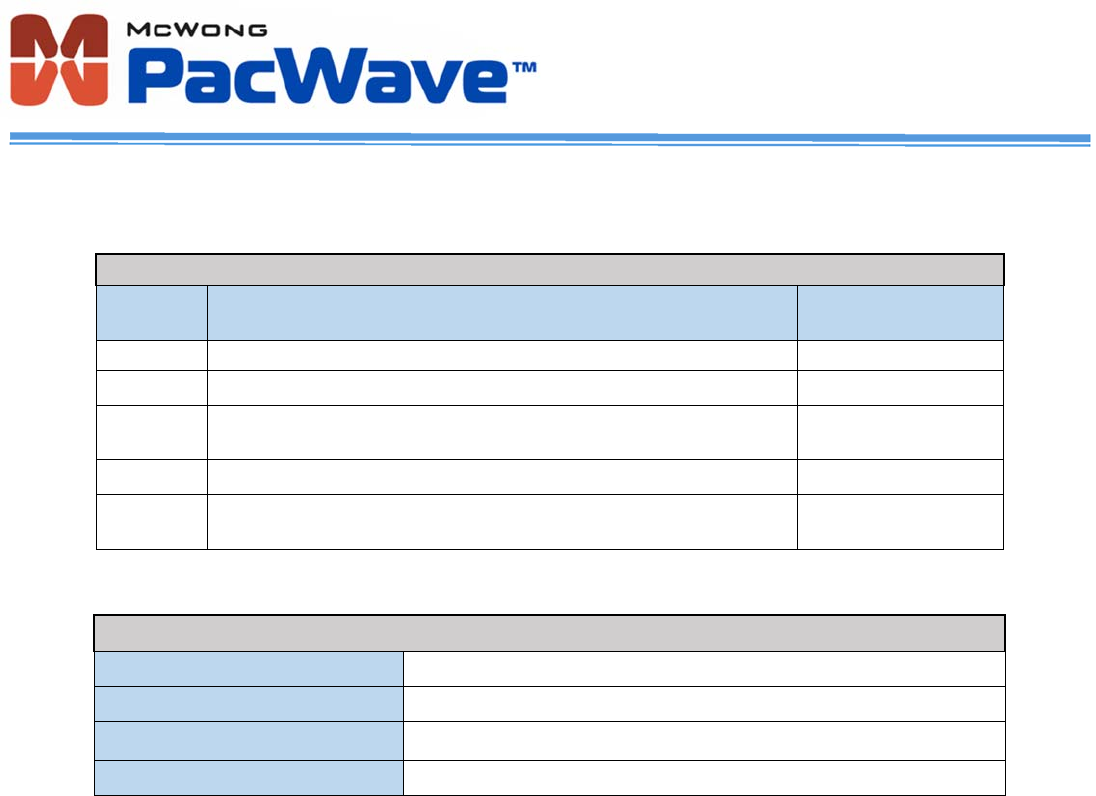
ELECTRICALSPECIFICATIONS(cont.)
CurrentConsumption(T
ambient
=25°C)
ModeDescriptionTotalTypical
Currentat3V
DormantAllfunctionsareshutdown.ToggleWAKEpintowakethemup.<900nA
HibernateEverythingoffexceptforthesleepclockandVCCpads.<1.9μA
Deep
Sleep
VCCpads,sleepclock,RAM,digitalcircuits,SMPSareon.2.2ms
wake‐uptime.<5μA
IdleMCUidling~1mA
RX/TX
ActiveRFactive~16mA@3Vpeak
current
GeneralCharacteristics
ModelNameWCM‐01
ProductDescriptionBluetoothSmart(BLE)wirelessmodule
Dimensions
(a)
24mmx28.5mmx3.75mm(W*L*T)
Weight3g±0.1g
(a)
Thickness=4.67mmwhenincludingtheheightofthe6‐pinreceptacle.

Bluetooth®SmartModule
Datasheet
MECHANICALDATA(cont.)
NOTE:Forbestperformance,themoduleshouldbeconnectednearorontheoutsideedgeofthehostPCB
withnothingunderneaththeantennaportion.
2.00mm
(pitch)
4.00mm2.00mm
6.05mm
3.56mm
Bluetooth®SmartModule
Datasheet
APPLICATIONINFORMATION
HOSTINTERFACE
ThemoduleincorporatesoneUniversalAsynchronousReceiver/Transmitter(UART)interfacededicatedtothehostfor
communicationtoandfromthemodule.AlsoavailabletothehostisoneGeneralPurposeInput/Output(GPIO)anda
WAKEinterruptinputusedtowakeupthemodulefromalowpowersleepmode.Thehostsupplies1.8V‐3.6VDCand
groundtopowerthemodule.
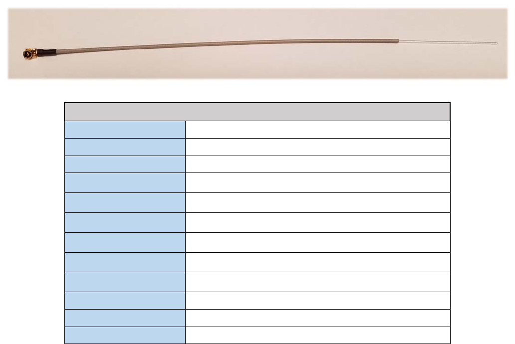
EXTERNALANTENNA
ThemoduleiscertifiedforuseonlywiththefollowingFCCapprovedantenna.
NOTE:UseofotherantennatypesorthesametypewithahighergainisnotallowedwithoutadditionaltestingandFCC
approval.
FCCApprovedAntennaSpecifications
ManufacturerShenzhenTaidaCenturyTechnologyCo.,Ltd
PartNumber1012
TypeWhipStraight(Wire)
WireLength150mm
MaterialofRadiatorCu
ConnectorIPEX(U.FL,female)
S.W.R<=2.0@2400‐2500MHz
Gain(Typical)2.0dBi@2450MHz//PeakGain
Impedance50Ohm
PolarizationLinear
OperatingTemperature‐30°Cto+85°C
StorageTemperature‐30°Cto+85°C
FEDERALCOMMUNICATIONSCOMMISSION(FCC)STATEMENTS
ThePacWave™ModulecomplieswithPart15oftheUnitedStatesofAmericaFCCrulesandregulations.TheOriginal
EquipmentManufacturer(OEM)mustcomplywiththeFCCcertificationrequirements.
15.21Anychangesormodificationsmadetothemodulewithoutthemanufacturer’sapprovalcouldvoidtheuser’s
authoritytooperatethemodule.
15.105(b)ThisequipmenthasbeentestedandfoundtocomplywiththelimitsforaClassBdigitaldevice,pursuantto
part15oftheFCCrules.Theselimitsaredesignedtoprovidereasonableprotectionagainstharmfulinterferenceina
residentialinstallation.Thisequipmentgenerates,usesandcanradiateradiofrequencyenergyand,ifnotinstalledand
usedinaccordancewiththeinstructions,maycauseharmfulinterferencetoradiocommunications.However,thereis
noguaranteethatinterferencewillnotoccurinaparticularinstallation.Ifthisequipmentdoescauseharmful
interferencetoradioortelevisionreception,whichcanbedeterminedbyturningtheequipmentoffandon,theuseris
encouragedtotrytocorrecttheinterferencebyoneormoreofthefollowingmeasures:
Reorientorrelocatethereceivingantenna.
Increasetheseparationbetweentheequipmentandreceiver.
Connecttheequipmentintoanoutletonacircuitdifferentfromthattowhichthereceiverisconnected.
Consultthedealeroranexperiencedradio/TVtechnicianforhelp.
PLEASENOTETHEMODULEOPERATIONISSUBJECTTOTHEFOLLOWINGTWOCONDITIONS:
1. Thisdevicemaynotcauseharmfulinterferences.
2. Thisdevicemustacceptanyinterferencereceived,includinginterferencethatmaycauseundesiredoperation.
RADIATIONEXPOSURESTATEMENT
ThisequipmentcomplieswithFCCradiationexposurelimitssetforthforanuncontrolledenvironment.Endusersmust
followthespecificoperatinginstructionsforsatisfyingRFexposurecompliance.Thistransmittermustnotbeco‐located
oroperatinginconjunctionwithanyotherantennaortransmitter,andtheendproductmusthaveaseparationdistance
ofatleast20mmfromall persons.WiththedocumentedmaxoutputpowerthemodulemeetstheFCCSARExemptionto
complywithanyapplicableRFexposurerequirementsinitsfinalconfiguration.
ORIGINALEQUIPMENTMANUFACTURER(OEM)NOTES
TheOEMmustcertifythefinalendproducttocomplywithunintentionalradiators(FCCSections15.107and
15.109)beforedeclaringcomplianceofthefinalproducttoPart15oftheFCCrulesandregulations.Integration
intodevicesthataredirectlyorindirectlyconnectedtoAClinesmustaddwithClassIIPermissiveChange.
TheOEMmustcomplywiththeFCClabelingrequirements.Ifthemodule’slabelisnotvisiblewheninstalled,
thenanadditionalpermanentlabelmustbeappliedontheoutsideofthefinishedproductwhichstates:
“ContainstransmittermoduleFCCID:ZZOWCM‐01”.Additionally,thefollowingstatementshouldbeincluded
onthelabelandinthefinalproduct’susermanual:“ThisdevicecomplieswithPart15oftheFCCRules.
Operationissubjecttothefollowingtwoconditions:(1)Thisdevicemaynotcauseharmfulinterferences,and
(2)thisdevicemustacceptanyinterferencereceived,includinginterferencethatmaycauseundesired
operation.”
Themoduleislimitedtoinstallationinmobileorfixedapplications.Separateapprovalisrequiredforallother
operatingconfigurations,includingportableconfigurationwithrespecttoPart2.1093anddifferentantenna
configurations.
Amoduleormodulescanonlybeusedwithoutadditionalauthorizationsiftheyhavebeentestedandgranted
underthesameintendedend‐useoperationalconditions,includingsimultaneoustransmissionoperations.
Whentheyhavenotbeentestedandgrantedinthismanner,additionaltestingand/orFCCapplicationfiling
mayberequired.Themoststraightforwardapproachtoaddressadditionaltestingconditionsistohavethe
granteeresponsibleforthecertificationofatleastoneofthemodulessubmitapermissivechangeapplication.
Whenhavingamodulegranteefileapermissivechangeisnotpracticalorfeasible,thefollowingguidance
providessomeadditionaloptionsforhostmanufacturers.Integrationsusingmoduleswhereadditionaltesting
and/orFCCapplicationfiling(s)mayberequiredare:(A)amoduleusedindevicesrequiringadditionalRF
exposurecomplianceinformation(e.g.,MPEevaluationorSARtesting);(B)limitedand/orsplitmodulesnot
meetingallofthemodulerequirements;and(C)simultaneoustransmissionsforindependentcollocated
transmittersnotpreviouslygrantedtogether.
This Module is full modular approval, it is limited to OEM installation ONLY.
Integration into devices that are directly or indirectly connected to AC lines must add with Class II Permissive Change.
(OEM) Integrator has to assure compliance of the entire end product incluld the integrated Module.
Additional measurements (15B) and/or equipment authorizations (e.g Verification) may need to be addressed
depending on co-location or simultaneous transmission issues if applicable.
(OEM) Integrator is reminded to assure that these installation instructions will not be made available to the end user
of the final host device.