MYLAPS AMBGP1 RC Model Car Lap Timing Transmitter User Manual users manual
MYLAPS BV RC Model Car Lap Timing Transmitter users manual
MYLAPS >
users manual
MANUAL
MANUALMANUAL
MANUAL
AMBrc system
AMBrc systemAMBrc system
AMBrc system

AMB i.t. B.V. Installation Manual AMBrc - Rev. 1.1b 1
Contents
Page
1. INTRODUCTION..................................................................................................................................2
2. INSTALLATION OF THE DETECTION LOOP...............................................................................4
3. INSTALLATION OF THE AMBRC DECODER .............................................................................10
4. INSTALLATION OF THE DIRECT POWERED TRANSPONDER..............................................12
5. INSTALLATION OF THE RECHARGEABLE TRANSPONDER................................................. 13
6. CHARGING THE TRANSPONDER.................................................................................................14
7. OPERATING THE SYSTEM / TROUBLE SHOOTING ................................................................15
8. TECHNICAL SPECIFICATIONS......................................................................................................17
9. EC AND FCC REGULATIONS .........................................................................................................18
AMB i.t. Manual number: AMBrc/Rev. 1.1b
All rights reserved
This publication is to be used for the standard model of the product of the type given on the cover page.
This publication has been written with great care. However, the manufacturer cannot be held responsible, either for any
errors occurring in this publication or for their consequences.

AMB i.t. B.V. Installation Manual AMBrc - Rev. 1.1b 2
AMB i.t. B.V. Installation Manual AMBrc - Rev. 1.1b 3
1. Introduction
The AMBrc system is specially designed to time and score RC model car races. The
signal sent by an AMBrc transponder mounted on each RC model car is picked up by the
detection loop, which is installed in the track. This detection loop is connected to the
AMBrc decoder, via a coax cable. The decoder timestamps the received transponder
signals and sends this data via a RS232 cable to a connected computer. The decoder is
powered by a 12V mains adapter. Two types of transponders are available: a battery
powered transponder and a direct powered transponder. These transponders each
generate a unique number, which enables you to identify each RC car on the track. An
AMBrc transponder is always active when charged or powered by the RC car receiver
(in case of the direct powered transponder).
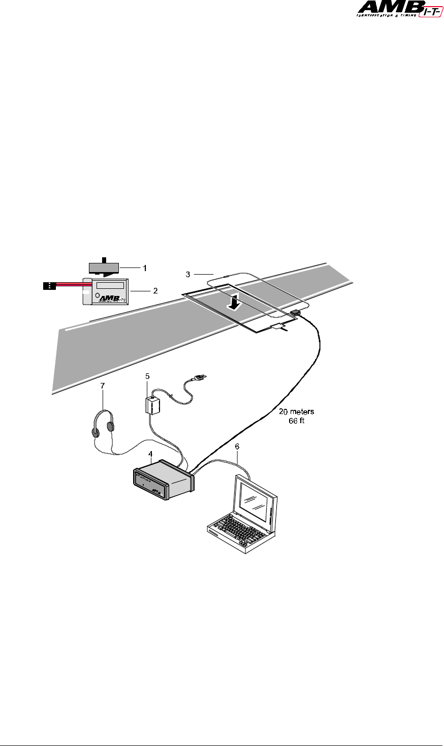
System components
1. AMBrc rechargeable transponder (part number 1301)
2. AMBrc direct powered transponder (part number 1302)
3. Detection loop, coax cable and connection box(part number 4701)
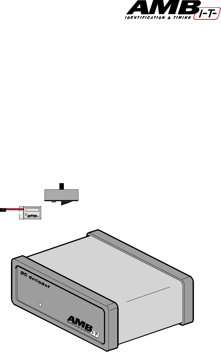
4. AMBrc decoder (part number 3301)
5. Adapter for AMB decoder (part number 6501)
6. Connection cable RS232 (part number 6201)
7. Headphones for decoder (part number 6701)
Not in picture: charger rack (part number 2421)
AMB i.t. B.V. Installation Manual AMBrc - Rev. 1.1b 4
2. Installation of the Detection loop
The AMB detection loop is made of a special water-resistant wire to guarantee durability
and has the resistor already installed. Keep the resistor opposite to the connection box
(the box that connects the coax cable to the loop).
Loops installed in re-enforced concrete may suffer from a noticeable loss of sensitivity
(less reach of the transponders) especially at wider tracks, since the steel underneath the
loop forms short-circuited loops. This weakens the signal from the loop. If unavoidable,
put the loop where the track is the least wide and put the loop wire in no deeper than
necessary.
Installing the loop:
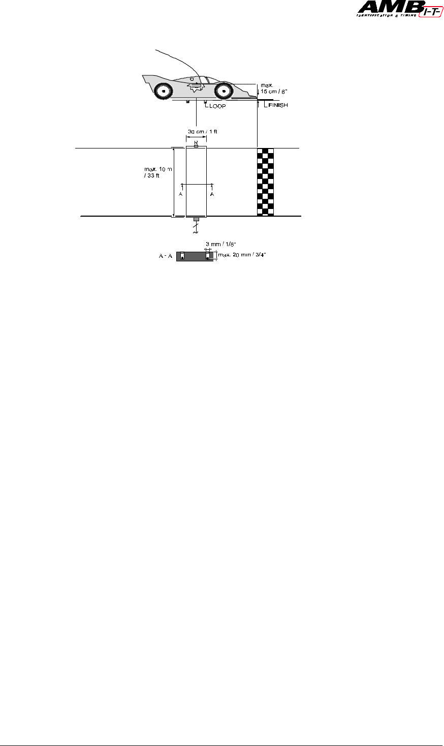
1. The detection loop must be positioned in such a way that the transponder is in the
middle of the two loop wires when the front of the RC model car is above the finish
line. If there is a possibility of RC model cars running outside the track, you may need
to extend the loop, but at all times keep the loop within 10 m / 33ft maximum width.
Keep the extensions as short as possible.
2. Cut the slots in the track maximum 2 cm / 3/4” deep and 30 cm / 1 ft apart, with a
suitable cutting disc/saw. To ensure one hundred percent detection, make sure RC
model cars can not pass outside the detection loop.
3. Put the wires of the detection loop in the slots and cut the excess length of the
detection loop wires.
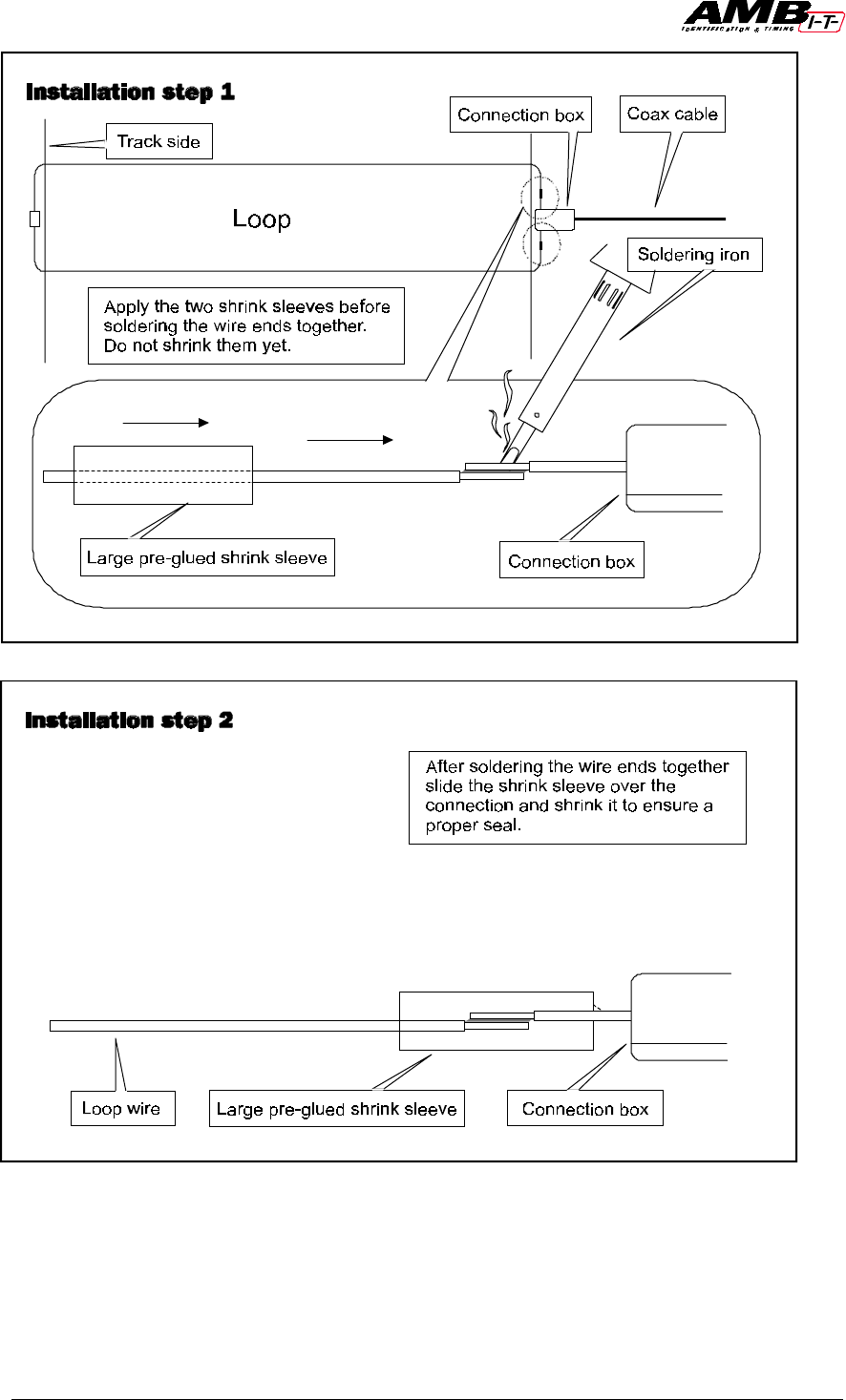
4. Put the heat shrinkage sleeves over both of the detection loop wire ends. Solder the
wire ends to the short wires of the connection box. Put both the shrinkage sleeves over
the solder connections and shrink them by holding them over a heat source.
5. Fill the slot with silicon. Make sure the silicon is fully under the surface of the track,
otherwise the tires may pull out the silicone. For OFF-ROAD use cover the loop with
carpet or similar. The carpet can be covered with sand.
6. The detection loop is sensitive to interference, possibly emitted by nearby cables. To
avoid possible interference keep all cables 3 m / 10 ft or more away.

AMB i.t. B.V. Installation Manual AMBrc - Rev. 1.1b 5
7. All loop wires must be installed according to the drawing in order to avoid a serious
degradation in performance (excess loop wire must be cut).
8. As the reach of AMBrc loop can be up to 90 cm / 3", especially when the noise
(interference) level is low, transponders on other parts of the track should not be able
to get closer to the loop than 90cm / 3".
9. If the coax cable from the loop to the decoder has to pass underneath the track (pit
lane), please make sure the coax cable is at least 2,5 cm / 1” underneath the track, to
avoid detection of passing transponders over the cable.
AMB i.t. B.V. Installation Manual AMBrc - Rev. 1.1b 6
AMB i.t. B.V. Installation Manual AMBrc - Rev. 1.1b 7
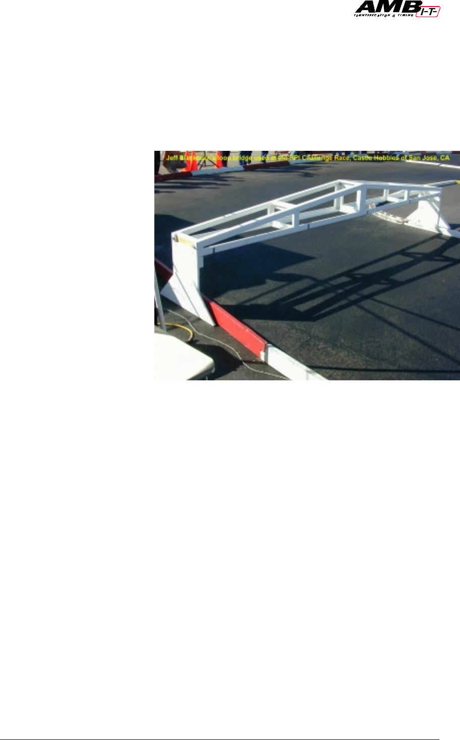
Loop installation for temporary tracks.
In some situations it may not be possible to have the detection loop installed permanently
in the track. This can be the case with temporary tracks, like indoor race events and
parking lot racing. In that case a detection loop installed on a bridge can be used. Do not
make this bridge of any type of metal or carbon fiber, as these materials will highly
reduce the sensitivity of the loop, resulting in far less reach of the transponder.
For temporary loop
installations, the loop wires
may be connected to the
connection box wires with
help of a good quality
connector such as a terminal
block. (Please note that bad
connections in a loop or coax
connections are by far the
most frequent cause of
substandard performance).
For temporary loops any wire
similar to the AMB loop wire
can be used. Opposite to the
connection box a resistor of
470-ohm (0.15-1 watt) must
be installed. For best results
please solder all joints and
insulate well. For outdoor
soldering a propane fired
soldering iron works best.
When using a bridge make sure the detection loop has a width of 45 cm / 1.5 ft. The
bridge should cover the track width and no RC model cars should be able to pass outside
the bridge. The connection box must be mounted on top of the bridge in order to avoid
loose detection wires, which can cause interference. At all times, keep all wiring as short
as possible. Construct the bridge with sufficient rigidity so it can withstand crashes from a
RC model car. To make sure the received transponder signal is strong enough, the
distance between the bridge and the track may not be more than 45 cm / 1.5 ft. Preferably
keep the height of the loop on the bridge as low as possible.
Compared to the in-track loop, the downside of a bridge is the greater distance between
the passing transponder and the detection loop resulting in a weaker signal for the
decoder.
At sundown and at night, the interference from short wave radio signals intensifies
strongly and may occasionally cause the transponder signals get swamped by the
interference. To prevent this from occurring it is advisable to keep the bridge as short
(less than 3 m / 10 ft) and low as possible (less than 45 cm / 1.5 ft).
Jeff Blackborn’s loop bridge used in the HPI Challenge race,
Castle Hobbies of San Jose, CA
AMB i.t. B.V. Installation Manual AMBrc - Rev. 1.1b 8
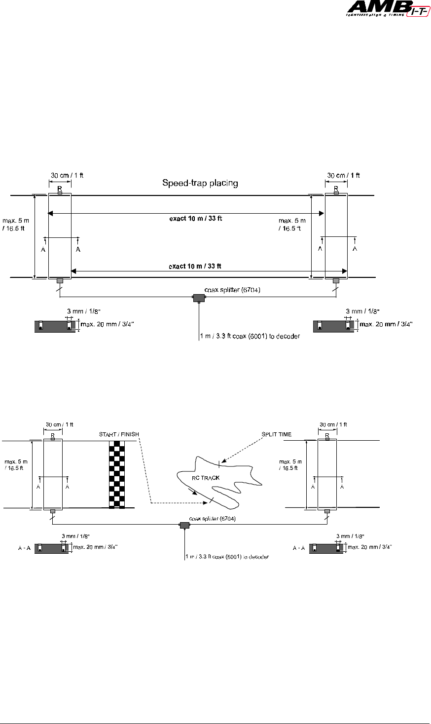
Speed measurement and split time
For speed measurements two loops have to be installed at an exact distance of 10 m / 33ft
of each other at the fastest point of the track. For split time, the second loop can be
installed at any desired measure point of the track. Whenever using two loops the
maximum width that can be used is 5 m / 16.5 ft per loop. Via an AMB coax splitter
and extra coax cable (part numbers 6704 and 6001/6002/6003) the two loops are
connected to the AMBrc decoder. Using two loops will result in a weaker signal for the
connected decoder. If very high noise (interference) levels occur, as may happen at night,
the speed or split-time loop may have to be disconnected.
Loop installation for speed trap setup.
Loop installation for split time setup
As the AMBrc decoder can not distinguish between transponder signals coming from the
finish, speed or split time loop, permanent manual supervision is necessary. For instance,
when a car stops in between the two loops used for the speed trap for longer than the
minimum lap time set in the software, the software will add a lap when the car passes the
second speed loop. The best way to avoid this is to use a decoder for the finish line and a

AMB i.t. B.V. Installation Manual AMBrc - Rev. 1.1b 9
second decoder for the speed and/or split time loop. Special designed software is
necessary.
For speed measurements the AMBrc decoder has to be set into speed-trap mode with the
help of specially designed (AMB) software. The speed-trap mode is indicated on the
AMBrc decoder by rapid flashing of the green LED on the front panel. In speeds trap
mode the decoder detects the same transponder again after 0.2 seconds instead of the
standard 2 seconds.
AMB i.t. B.V. Installation Manual AMBrc - Rev. 1.1b 10
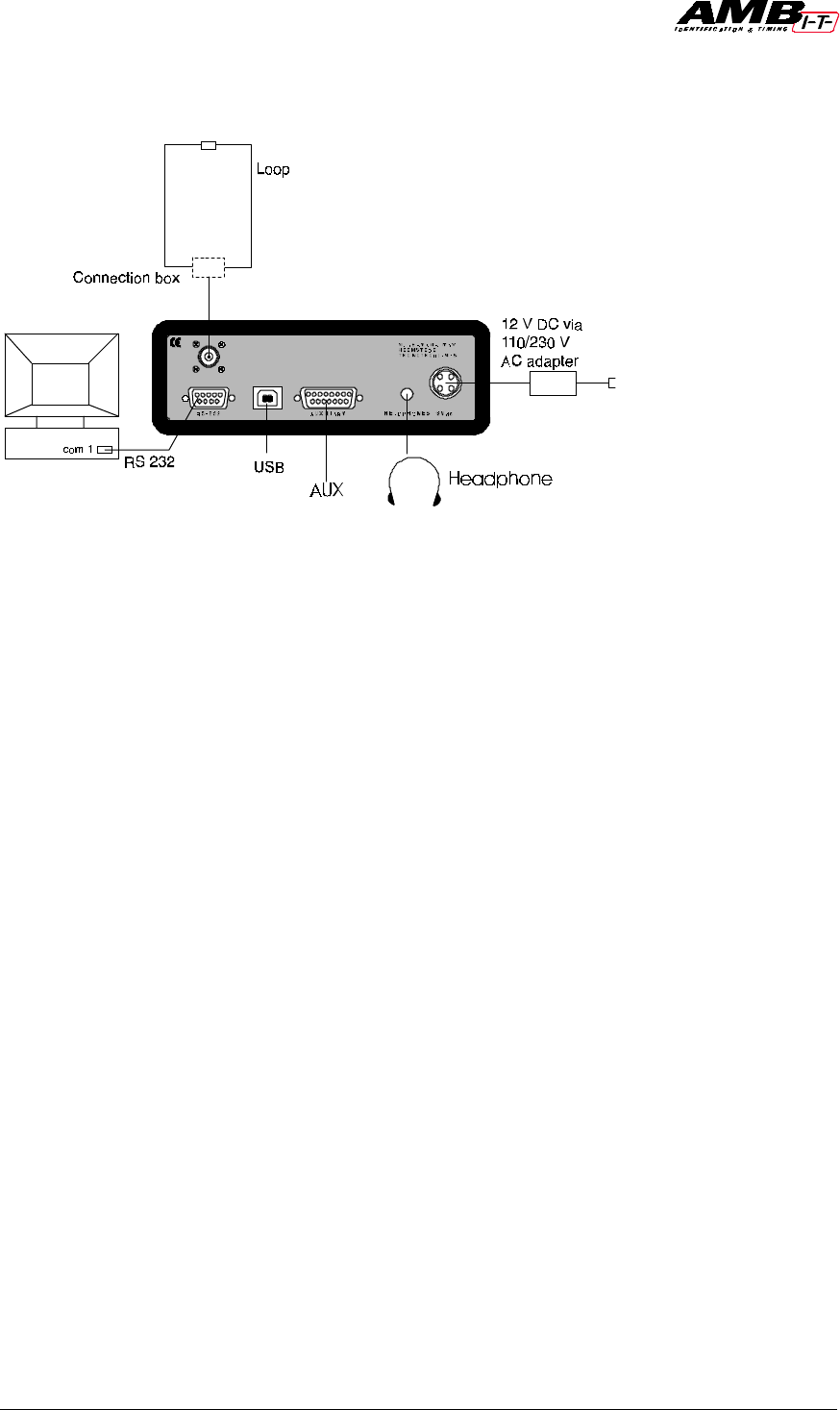
3. Installation of the AMBrc decoder
The decoder is a precision instrument. Please handle it with care and keep the
decoder out of direct sunlight and humidity.
1. Connect the 75-Ohm double shielded coax cable to the AMBrc decoder. Keep the
coax cable at least 30 cm / 1 ft away from other cables to avoid interference.
2. Connect the RS232 cable between the AMBrc decoder and the RS232 port of the
computer (a straight pin to pin RS232 connection cable is needed, such as AMB part
number 6201). Connect the headphone. A beep will sound for every passing
transponder providing an easy check on proper operation.
3. Connect the 12V adapter to the decoder and mains.
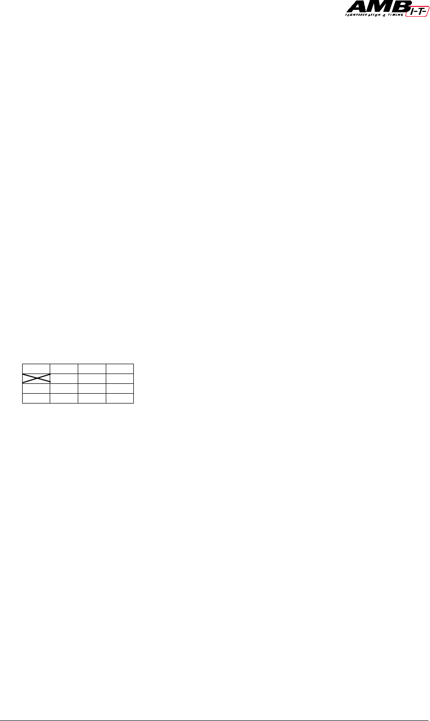
4. To use the opto coupled inputs (for instance for a photocell) or the opto coupled
outputs, connect it using the scheme and table below. The synchronized. input, which
is identical to the photocell input, enables you to synchronize multiple decoders
running. Both photocell and sync. input need a 4-12 VDC (5-15 mA) power source.
Pins 8 and 15 may be used for this purpose, but for reasons of possible interference an
external power source is preferred (i.e. 9V battery).
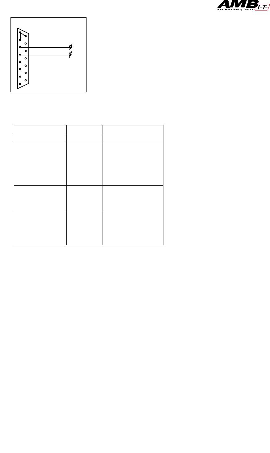
AMB i.t. B.V. Installation Manual AMBrc - Rev. 1.1b 11
Pin Signal
Power Supply 8+15 4.5 V 50 mA
Opto coupled
inputs 5
6
7
12
13
ground
opto 1 - input
opto 1 + input
opto 2 - input
opto 2 + input
Sync input 1+9
10
11
Ground
Sync – input
sync + input
Opto output 4
14
2
3
opto 1 - output
opto 1 + output
opto 2 - output
opto 2 + output
The opto outputs are under software control and may be used to drive electronics that
may be used for start lights. The opto outputs are connected to the transistor in the opto
coupler, the + is connected to the collector and the – to the emitter of the transistor.
Maximum allowed current through the transistor is 10mA.
The AMBrc decoder is equipped with a USB interface which is for future use, but it can
currently be used to get power from a connected (laptop) computer. In that case you may
also use the 12VDC power input for backup power.
The AMBrc decoder receives the signal of each passing transponder and combines the
transponder number with the exact passing time. The decoder sends the information to a
computer on which (AMB) timing software is running.
An easy check on proper operation of each passing transponder is done with help of a
headphone, since every transponder passing generates a “beep” signal.
At power-up the AMBrc decoder will beep 3 times and gives AMB20 compatible output
to support AMB20 software. AMBrc software will trigger the AMBrc decoder for AMBrc
output.
15
9
8
1
Auxiliary connector
to photocell
AMB i.t. B.V. Installation Manual AMBrc - Rev. 1.1b 12
4. Installation of the Direct Powered Transponder
The transponder must be mounted horizontally at all times, preferably inside the RC
model car. The position of the transponder must be identical in all RC model cars
competing in the race.
Transponders may not be positioned more than 15 cm / 6” away from the detection loop,
with no metal or carbon fiber in-between. It is preferable to mount the transponder as
close as possible to the detection loop. Make sure the transponder can not get detached
during a race.
To mount the direct powered transponder a nut and bolt can be used. Double-sided
sticky tape can be used, but this is not advised when liquid fuels are used in RC model
cars.
Locate the direct powered transponder in your RC model car in such way that it has a
free view at the detection loop. Keep the power wire neat and tidy in the RC model car so
it can not give you any trouble while driving the RC model car.
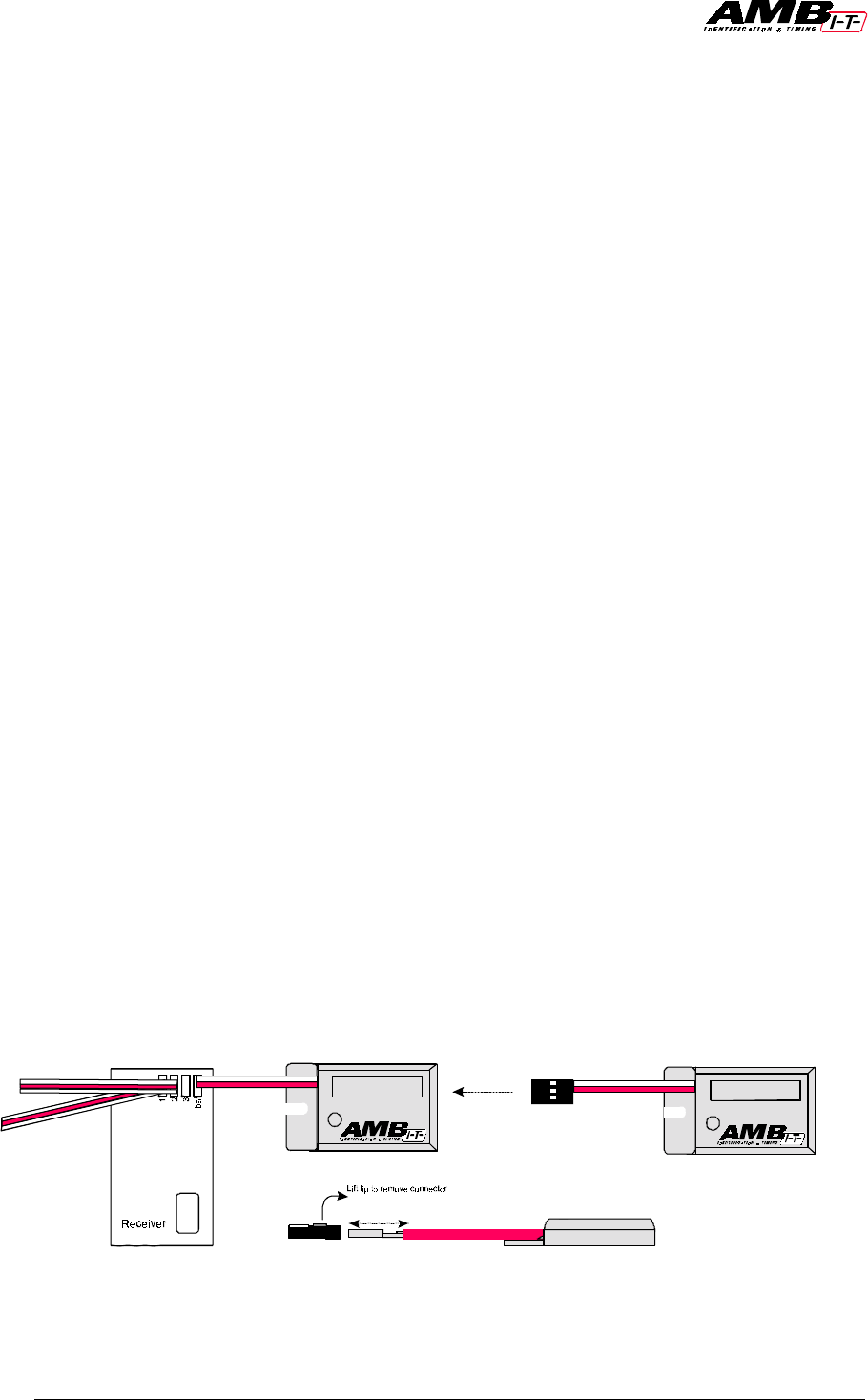
The power connector is a standard servo plug. This servo plug can be connected to a free
channel of the radio receiver. This channel can be a 3rd channel or battery channel. When
no free channel is available a Y-splitter servo wire can be used to connect the direct
powered transponder to your radio receiver. Your local hobby store can provide you with
a Y-splitter servo wire if necessary.
If the polarity of the servo plug does not match the polarity of the radio receiver, you can
change this (red wire is +). This is done by very carefully lifting the plastic lugs of the
servo plug with a hobby-knife (be careful not to cut yourself). When the plastic lugs are
lifted you can very carefully remove the connectors from the plug. Reinstall the
connectors into plug according to the polarity of the radio receiver you use. Push the
plastic lugs very carefully back into the servo plug and make sure the connectors are
fully seated into the plug.
Whenever power is applied to the radio receiver, the direct powered transponder will
show a green LED on both sides. These green LEDS indicate that the direct powered
transponder is working.
Make sure the transponder can not get detached during a race.
AMB i.t. B.V. Installation Manual AMBrc - Rev. 1.1b 13
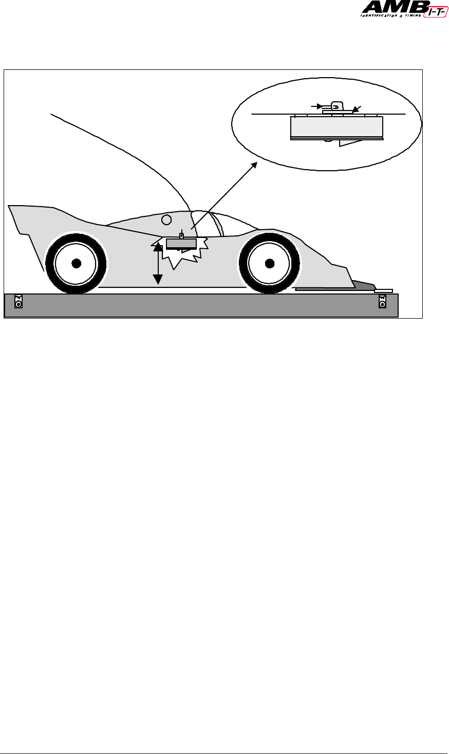
5. Installation of the rechargeable transponder
The transponder must be mounted horizontally at all times, preferably inside the RC
model car against the side, with the fixing pin pointing upwards or downwards. The
position of the transponder must be identical in all RC model cars competing in the race.
Put a washer around the fixing pin and fix the transponder with a fixing clip.
Transponders may not be positioned more than 15 cm / 6’’ (away) from the detection
loop, with no metal or carbon fiber between it. It is preferable to mount the transponder
as close as possible to the detection loop. Make sure the transponder can not get detached
during a race.
For OFF-ROAD RC model cars, the transponder may be fixed underneath the rear wing
of the RC model car.
When the pin has been forcefully removed from the transponder, the transponder cover
can be replaced (part number 00551102).
Body clip Washer
Max 15 cm
(6”)

AMB i.t. B.V. Installation Manual AMBrc - Rev. 1.1b 14
6. Charging the transponder
When charged, the AMBrc transponder constantly emits its magnetic output signal.
Battery capacity is sufficient for 18 hours.
Charging must be done in the AMB charger rack, preferably at room temperature since
Nimh cells do not charge well at temperatures below 14°C/57°F. When charging, the red
LED in each transponder indicates it is charging. A green LED indicates that the
transponder is fully charged.
The charging cycle for an empty transponder is as follows:
1. During the first five hours the transponder will be fast charged, indicated by a steady
red LED on the transponder
2. After five hours of charging the charging cycle will be replaced with a slower charge,
as indicated by a blinking red LED (LED blinks every second).
3. Full charge is reached after a total of 10 hours of charging and is indicated by a steady
green LED. A full charge is sufficient for a minimum of 18 hours of operating time.
4. When the transponder is removed from the charger rack the LED will blink green
(when sufficiently charged).
5. A low battery voltage is indicated by a blinking red LED (LED blinks every second).
The amount of time the transponder blinks red (when nearly empty) depends of the
amount of charge the battery has received. When charged until full, the transponder may
blink the red LED for half an hour or longer. If a transponder is re-charged from partly
empty and the 5 hours fast charge have past, the transponder will always re-charge at the
slower charge rate.
When transponders have not been used for a couple of months, the first re-charge will not
be fully effective. To ensure maximum capacity, give the transponders a full charge and
discharge cycle before use. Use the full charge/ discharge cycle to check if transponders
have sufficient operating time.
Keep transponders at least 1 meter / 3 ft away from coax cables and the decoder, to avoid
unwanted inputs.
Warning: Airline regulations demand all electronics to be switched-off when on board
aircraft. The AMBrc transponders switch themselves off when the Nimh cells are empty.
When airline travel is expected after a race event, do not charge longer than necessary to
proceed with the races. The transponder switches on as soon as re-charging starts.

AMB i.t. B.V. Installation Manual AMBrc - Rev. 1.1b 15
7. Operating the system / Trouble shooting
Start-up
To enable compatibility with the widely used AMB20 software from various sources, the
AMBrc decoder starts-up in AMB20 mode and uses the data format of the AMB20
decoder. As the AMB20 system uses only the transponder numbers 1 to 20, the AMBrc
decoder in AMB20 mode sends only the last digit of the 7-digit transponder number. For
example: AMBrc transponder number 1234567 shows as transponder number 7, but
transponder number 6543217 shows up as transponder number 7 as well (not as 17). In
order to have the full benefit of the 7-digit individual and unique transponder number
suitable AMBrc software must be used, which makes the AMBrc decoder to switch over
from AMB20 mode to AMBrc mode.
Led indications
When switched-on the decoder shows a red LED and is in the initial AMB20 stop mode.
The decoder must be started using proper (AMB20) software. When started, the LED
shows green. Each time the decoder sends data, the LED flashes red.
Noise level
Every 5 seconds the AMBrc decoder sends the average background noise (interference)
level to the computer (not when in AMB20 mode). Noise becomes interference when it
becomes noticeable (less reach of the transponders). The noise (strength) value has a
range from 0 to over 200. Noise-level, as shown by the AMB software, should preferably
not exceed 30. The received transponder signal-strength should be 60 or more above
noise level to ensure perfect functioning of the system. Any electrical switch in the area
or, usually at night, by short-wave radio stations can cause peaks in background noise
level. Electronic equipment may also cause an increased background noise level. Switch-
off the suspected equipment to find out. If you are using a bridge, please make sure the
bridge is as short (less than 3m / 10 ft) and as low (less than 45 cm / 1.5 ft) as possible. In
most cases, an increased noise level is the result of improper connections, insulation or
wrong layout of the detection loop and/or coax cable. Also cables carrying interference
from connected equipment installed too close to the detection loop are frequently the
source of unwanted noise.
Signal strength
Signal strength, as shown by AMBrc software, should preferably be not lower than 90 and
at least 60 above the indicated background noise. Higher figures, for instance due to
transponders closer to the track, give a higher immunity against interference.
Transponders in a wrong position, which give strength of less than 50, will not be
detected.
Hits
The number of hits, as shown by AMBrc software, is an indication of the number of
repeated contacts during a passing. The number of hits varies with the speed of a passing
transponder. Transponders should not get closer than 2.5cm / 1” to avoid interfering on
each other signals, resulting in low hits. Hits less than 10 indicate very high speeds or
substandard performance. If low hits occur at low speeds, please check the loop
installation and noise level.

AMB i.t. B.V. Installation Manual AMBrc - Rev. 1.1b 16
Problems
Most problems concerning the functioning of the system are due to bad connections or
improper installation. Mobile phones and other forms of personal radio communications
do not affect AMB i.t. systems.
If you still have questions or problems, please contact AMB i.t. by fax or e-mail supplying
the following data:
1. Description of the problem and the purpose the system was used for.
2. Decoder and transponder type and their serial numbers.
3. Worst noise level and minimum indicated transponder signal strength.
4. Use of in-track or bridge detection loop.
To contact AMB: please see address chapter 9.

AMB i.t. B.V. Installation Manual AMBrc - Rev. 1.1b 17
8. Technical Specifications
AMBrc Decoder
Dimensions : 120x170x55mm / 4.7"x6.7”x2.2"
Weight : 0.8 kg / 1.9lb
Clock stability : 25 PPM
Timebase Resolution : 0.001s in AMBrc mode
Timing Resolution : better than timebase of used AMB transponder type
Memory : 5000 passings
Temperature range : 0 - 50C / 32 - 122F
Humidity range : 10% to 90% relative
Operating voltage range : 10 to 16VDC (12VDC input)
Power consumption : 0.1A via 12VDC input
: 0.3A via USB
Output : RS232, 9600 baud, 8 bit, 1 stop-bit, no parity
Number of loops : 1 (or 2 with help of T splitter)
Max. track width : max. 10m (33’), when 2 loops are used: 5 m / 16.5”
Aux. Inputs : 3x opto coupled 4-12 VDC / 5-15 mA
Aux. Outputs : 2x opto coupled, max 10mA
Compatible with the following
AMB transponder types : AMBrc (rechargeable type), AMBrc direct power
USB connection : not implemented yet, but power can be applied.
AMBrc Rechargeable Transponder
Dimensions : 35x31x12 mm / approx. 1.4”x1.2”x 0.5”
Weight : 22 g
Humidity : max. 90% relative
Max. speed : 120 km/h / 75 mph.
Temperature range : 0-50 C / 32-122 F
Operating time : min. 18 hrs
Charge indicator : LED indicator green / red
Signal transfer : magnetic induction
Resolution timebase : 3 ms
Transponder position : max. height 15 cm / 6’’
Charging voltage : 3.3 VDC
Transponder Charger
Dimensions : 380x117x65 mm / approx. 15’’x5’’x3’’
Capacity : 20 transponders
Power supply : 10 to 16VDC / 0.4 A via 115/230 VAC adapter
AMBrc Direct Powered Transponder
Dimensions : 22x38x7 mm / approx. 0.9”x1.5”x 0.3”
Weight : 10 g
Humidity : max. 90% relative
Max. speed : 120 km/h / 75 mph.
Temperature range : 0-50 C / 32-122 F
Operating time : Unlimited
Signal transfer : magnetic induction
Resolution timebase : 3 ms
Transponder position : max. height 15 cm / 6’’
Power : Power feed from a free receiver channel (ch3 or batt)
Connection Plug : Connect using a standard servo plug
Operating Time : Active while external power applied
Power consumption : Uses less than10mA
Operating voltage : 4 –8 VDC
Detection Loop
Track width : max. 10 m / 33 ft (or 2x 5 m / 16.5 ft)
Coax to decoder : max. 200 m / 660 ft
Specifications are subject to change without notice
AMB i.t. B.V. Installation Manual AMBrc - Rev. 1.1b 18
9. FCC and CE regulations
The FCC regulations state that the following text must be put on a prominent position in the manual:
This equipment complies with part 15 of the FCC rules. Operation is subject to the following two conditions: (1) This equipment may not cause
harmful interference, and (2) this equipment must accept any interference received, including interference that may cause undesired operation.
Note: This equipment has been tested and found to comply with the limits for a Class B digital device, pursuant to part 15 of the FCC rules.
These limits are designed to provide reasonable protection against harmful interference in a residential installation. This equipment generates,
uses and can radiate radio frequency energy and, if not installed and used in accordance with the instructions, may cause harmful interference to
radio communications. However, there is no guarantee that interference will not occur in a particular installation. If this equipment does cause
harmful interference to radio or television reception, which can be determined by turning the equipment off and on, the user is encouraged to try
to correct the interference by one or more of the following measures:
• Reorient or relocate the receiving antenna.
• Increase the separation between the equipment and receiver.
• Connect the equipment into an outlet on a circuit different from that to which the receiver is connected
The required FCC ID’s are indicated on the transponders and decoder.
The EC regulations require a declaration of conformity and declaration of product quality assurance (see enclosed)
The regulations stipulate also that the following text must be indicated as Important Notice:
When equipment fulfills the regulations valid in one of the EC countries, this equipment may be imported and traded in any other EC country.
This is also the case for AMB equipment. Unfortunately the use of frequencies in is not (yet) harmonized, which means that the use of a given
frequency that is allowed in one EC country is not automatically allowed in another EC country and vice versa. This results in the fact that, in
some countries, you may buy (and sell) AMB equipment, but they may not be switched-on.
The AMB transponders operate on magnetic induction only, therefore they have no antenna, but a built-in coil instead. The transponders do not
produce an electromagnetic (radio) wave but only a magnetic wave. The difference between an electromagnetic (radio) wave and a magnetic
wave is that the electromagnetic wave travels by itself over great distances and the magnetic wave does not. Therefore AMB transponders do
not act as transmitters, have a very limited range and can therefore not interfere with any outside radio transmission.
The crossed out member states have restrictive use:
AUS B DK FIN
FDGRIRE
ILUXNL P
ESUK
AMB i.t. B.V. AMB i.t. US Inc.
Herenweg 29A 1631 Phoenix Blvd., Suite 11
2105 MB Heemstede College Park, GA 30349
The Netherlands U.S.A.
Tel: ++31 23 529 1893 Tel. 770-997-8882 / 877-426-2488
Fax: ++31 23 529 0156 Fax. 770-997-0699
Homepage: www.amb.nl Homepage: www.amb-us.com
E-mail: support@amb.nl E-mail: support@amb-us.com
Manufacturer US-Office
AMB i.t. B.V. Installation Manual AMBrc - Rev. 1.1b 19
Declaration of Conformity
We, the undersigned,
Company AMB i.t. Holding B.V.
Address, City Herenweg 29a, 2105 MB Heemstede
Country The Netherlands
Phone number +31 23 529 18 93
Fax number +31 23 529 51 82
certify and declare under our sole responsibility that the following equipment:
Product description / Intended use 5.0 MHz low power inductive laptiming system
EU /EFTA memberstates intended for use EU: Austria, Belgium, Denmark, Finland, France, Germany Greece,
Ireland, Italy, Luxembourg, the Netherlands, Portugal, Spain, Sweden,
United Kingdom
EFTA: Switzerland, Iceland, Lichtenstein, Norway
Restrictive use Those EU members where the 5.0MHz frequency is not allowed for this
application
Manufacturer AMB i.t. Holding B.V.
Brand AMBrc
Types AMB rc Decoder
AMB rc Transponder
AMBrc DP
AMBrc F102RP-5
is tested to and conforms with the essential radio test suites included in following standards:
Standard Issue date
EN 300 330
ETS 300 683
EN 60950
V.1.2.2. (May-1999)
June 1997
(1992), incl. A1(1993), A2(1993),A3(1995), A4(1997)
and therefore complies with the essential requirements and provisions of the Directive 1999/5/EC of the
European Parliament and of the council of 9 march 1999 on Radio equipment and Telecommunications
Terminal Equipment and the mutual recognition of their conformity and Annex IV (Conformity Assessment
procedure referred to in article 10(4)).
The following Notified Bodies have been consulted in the Conformity Assessment procedure:
Notified Body number Name and address
0122 NMi Certin B.V., POB 15, 9822 ZG Niekerk, The Netherlands
The technical documentation as required by the Conformity Assessment procedure is kept at the following
address:
Company AMB i.t. Holding B.V.
Address, City Herenweg 29a, 2105 MB Heemstede
Country The Netherlands
Phone number +31 23 529 18 93
Fax number +31 23 529 51 82
Drawn up in Heemstede, The Netherlands
Date June 21, 2000
AMB i.t. B.V. Installation Manual AMBrc - Rev. 1.1b 20
Name and function Harry van Dooren, General Manager
Declaration of Product Quality Assurance.
In accordance with the Conformity Assessment procedure referred to in article 10(3) of Directive
1999/5/EC of the European Parliament and of the Council of 9 march 1999 on Radio
equipment and Telecommunication Terminal Equipment and their mutual recognition of their
conformity (R&TTE directive) the following manufacturer:
Company AMB i.t. Holding B.V.
Address, City Herenweg 29a, 2105 MB Heemstede
Country The Netherlands
Phone number +31 23 529 18 93
Fax number +31 23 529 51 82
declares under its sole responsibility that it has taken the following measures in order that the
manufacturing process ensures compliance of the manufactured products with the technical
documentation as established by Circuit Technology Woerden B.V. under requirements of the
R&TTE Directive and with the requirements of the R&TTE directive that apply to them:
Number Measures taken in order that the manufacturing process ensures
compliance of the manufactured products
1Manufacturing of the equipment is done under iso9001 certification number 652035
(See copy of ISO 9001 certification attached)
2End product quality control is assessed on accordance with AMB i.t. Holding B.V. product
quality control procedures, as described and contained in document entitled AMBRC System
Quality Assurance, issue 21-06-2000, version 01
3Full operational test according to customer specifications
Above mentioned measures are related to production of the following product:
Brand AMBrc
Type AMB rc Decoder
AMB rc Transponder
AMBrc_DP
AMBrc_F102RP-5
Product description / Supplementary info 5.0 MHz low power inductive laptiming system
Drawn up in Heemstede, The Netherlands
Date June 21, 2000

AMB i.t. B.V. Installation Manual AMBrc - Rev. 1.1b 21
Name and function Harry van Dooren, General Manager