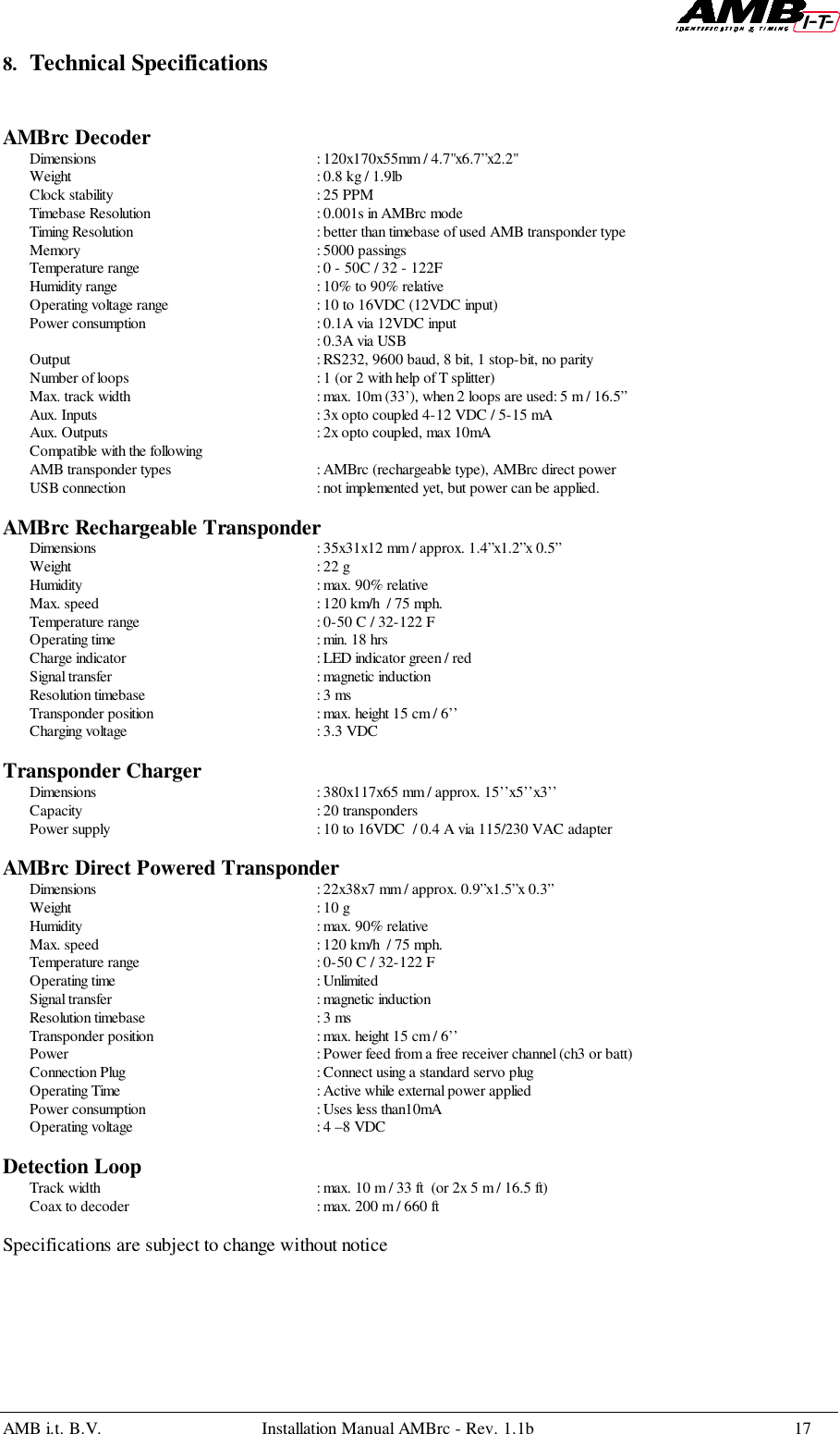
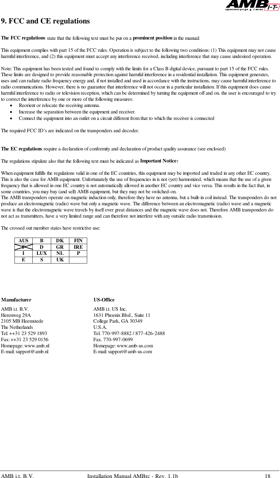
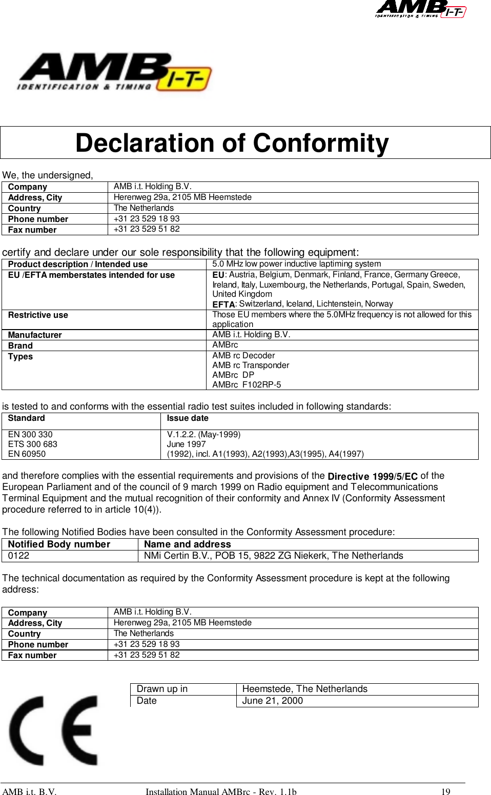
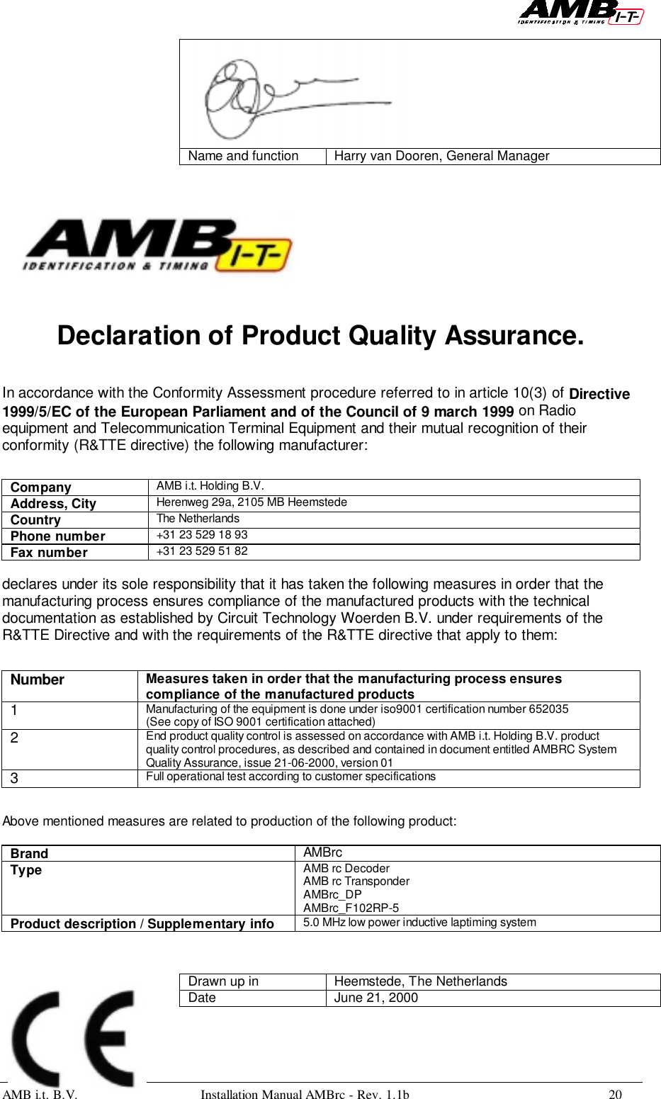
MYLAPS AMBGP3 RC Model Car Lap Timing Transmitter User Manual users manual

MYLAPS BV RC Model Car Lap Timing Transmitter users manual

users manual

MANUALMANUALMANUALMANUALAMBrc systemAMBrc systemAMBrc systemAMBrc system
AMB i.t. B.V. Installation Manual AMBrc - Rev. 1.1b 1Contents      Page1. INTRODUCTION..................................................................................................................................22. INSTALLATION OF THE DETECTION LOOP...............................................................................43. INSTALLATION OF THE AMBRC DECODER .............................................................................104. INSTALLATION OF THE DIRECT POWERED TRANSPONDER..............................................125. INSTALLATION OF THE RECHARGEABLE TRANSPONDER................................................. 136. CHARGING THE TRANSPONDER.................................................................................................147. OPERATING THE SYSTEM / TROUBLE SHOOTING ................................................................158. TECHNICAL SPECIFICATIONS......................................................................................................179. EC AND FCC REGULATIONS .........................................................................................................18AMB i.t.  Manual number: AMBrc/Rev. 1.1bAll rights reservedThis publication is to be used for the standard model of the product of the type given on the cover page.This publication has been written with great care. However, the manufacturer cannot be held responsible, either for anyerrors occurring in this publication or for their consequences.
AMB i.t. B.V. Installation Manual AMBrc - Rev. 1.1b 2
AMB i.t. B.V. Installation Manual AMBrc - Rev. 1.1b 31. IntroductionThe AMBrc system is specially designed to time and score RC model car races. Thesignal sent by an AMBrc transponder mounted on each RC model car is picked up by thedetection loop, which is installed in the track. This detection loop is connected to theAMBrc decoder, via a coax cable. The decoder timestamps the received transpondersignals and sends this data via a RS232 cable to a connected computer. The decoder ispowered by a 12V mains adapter. Two types of transponders are available: a batterypowered transponder and a direct powered transponder. These transponders eachgenerate a unique number, which enables you to identify each RC car on the track. AnAMBrc transponder is always active when charged or powered by the RC car receiver(in case of the direct powered transponder).System components1. AMBrc rechargeable transponder (part number 1301)2. AMBrc direct powered transponder (part number 1302)3. Detection loop, coax cable and connection box(part number 4701)4. AMBrc decoder (part number 3301)5. Adapter for AMB decoder (part number 6501)6. Connection cable RS232 (part number 6201)7. Headphones for decoder (part number 6701)Not in picture: charger rack (part number 2421)
AMB i.t. B.V. Installation Manual AMBrc - Rev. 1.1b 42. Installation of the Detection loopThe AMB detection loop is made of a special water-resistant wire to guarantee durabilityand has the resistor already installed. Keep the resistor opposite to the connection box(the box that connects the coax cable to the loop).Loops installed in re-enforced concrete may suffer from a noticeable loss of sensitivity(less reach of the transponders) especially at wider tracks, since the steel underneath theloop forms short-circuited loops. This weakens the signal from the loop. If unavoidable,put the loop where the track is the least wide and put the loop wire in no deeper thannecessary.Installing the loop:1. The detection loop must be positioned in such a way that the transponder is in themiddle of the two loop wires when the front of the RC model car is above the finishline. If there is a possibility of RC model cars running outside the track, you may needto extend the loop, but at all times keep the loop within 10 m / 33ft maximum width.Keep the extensions as short as possible.2. Cut the slots in the track maximum 2 cm / 3/4” deep and 30 cm / 1 ft apart, with asuitable cutting disc/saw. To ensure one hundred percent detection, make sure RCmodel cars can not pass outside the detection loop.3. Put the wires of the detection loop in the slots and cut the excess length of thedetection loop wires.4. Put the heat shrinkage sleeves over both of the detection loop wire ends. Solder thewire ends to the short wires of the connection box. Put both the shrinkage sleeves overthe solder connections and shrink them by holding them over a heat source.5. Fill the slot with silicon. Make sure the silicon is fully under the surface of the track,otherwise the tires may pull out the silicone. For OFF-ROAD use cover the loop withcarpet or similar. The carpet can be covered with sand.6. The detection loop is sensitive to interference, possibly emitted by nearby cables. Toavoid possible interference keep all cables 3 m / 10 ft or more away.
AMB i.t. B.V. Installation Manual AMBrc - Rev. 1.1b 57. All loop wires must be installed according to the drawing in order to avoid a seriousdegradation in performance (excess loop wire must be cut).8. As the reach of AMBrc loop can be up to 90 cm / 3", especially when the noise(interference) level is low, transponders on other parts of the track should not be ableto get closer to the loop than 90cm / 3".9. If the coax cable from the loop to the decoder has to pass underneath the track (pitlane), please make sure the coax cable is at least 2,5 cm / 1” underneath the track, toavoid detection of passing transponders over the cable.
AMB i.t. B.V. Installation Manual AMBrc - Rev. 1.1b 6
AMB i.t. B.V. Installation Manual AMBrc - Rev. 1.1b 7Loop installation for temporary tracks.In some situations it may not be possible to have the detection loop installed permanentlyin the track. This can be the case with temporary tracks, like indoor race events andparking lot racing. In that case a detection loop installed on a bridge can be used. Do notmake this bridge of any type of metal or carbon fiber, as these materials will highlyreduce the sensitivity of the loop, resulting in far less reach of the transponder.For temporary loopinstallations, the loop wiresmay be connected to theconnection box wires withhelp of a good qualityconnector such as a terminalblock. (Please note that badconnections in a loop or coaxconnections are by far themost frequent cause ofsubstandard performance).For temporary loops any wiresimilar to the AMB loop wirecan be used. Opposite to theconnection box a resistor of470-ohm (0.15-1 watt) mustbe installed. For best resultsplease solder all joints andinsulate well. For outdoorsoldering a propane firedsoldering iron works best.When using a bridge make sure the detection loop has a width of 45 cm  / 1.5 ft. Thebridge should cover the track width and no RC model cars should be able to pass outsidethe bridge. The connection box must be mounted on top of the bridge in order to avoidloose detection wires, which can cause interference. At all times, keep all wiring as shortas possible. Construct the bridge with sufficient rigidity so it can withstand crashes from aRC model car. To make sure the received transponder signal is strong enough, thedistance between the bridge and the track may not be more than 45 cm / 1.5 ft. Preferablykeep the height of the loop on the bridge as low as possible.Compared to the in-track loop, the downside of a bridge is the greater distance betweenthe passing transponder and the detection loop resulting in a weaker signal for thedecoder.At sundown and at night, the interference from short wave radio signals intensifiesstrongly and may occasionally cause the transponder signals get swamped by theinterference. To prevent this from occurring it is advisable to keep the bridge as short(less than 3 m / 10 ft) and low as possible (less than 45 cm / 1.5 ft).Jeff Blackborn’s loop bridge used in the HPI Challenge race,Castle Hobbies of San Jose, CA
AMB i.t. B.V. Installation Manual AMBrc - Rev. 1.1b 8Speed measurement and split timeFor speed measurements two loops have to be installed at an exact distance of 10 m / 33ftof each other at the fastest point of the track. For split time, the second loop can beinstalled at any desired measure point of the track. Whenever using two loops themaximum width that can be used is 5 m / 16.5 ft per loop. Via an AMB coax splitterand extra coax cable (part numbers 6704 and 6001/6002/6003) the two loops areconnected to the AMBrc decoder. Using two loops will result in a weaker signal for theconnected decoder. If very high noise (interference) levels occur, as may happen at night,the speed or split-time loop may have to be disconnected.Loop installation for speed trap setup.Loop installation for split time setupAs the AMBrc decoder can not distinguish between transponder signals coming from thefinish, speed or split time loop, permanent manual supervision is necessary. For instance,when a car stops in between the two loops used for the speed trap for longer than theminimum lap time set in the software, the software will add a lap when the car passes thesecond speed loop. The best way to avoid this is to use a decoder for the finish line and a
AMB i.t. B.V. Installation Manual AMBrc - Rev. 1.1b 9second decoder for the speed and/or split time loop. Special designed software isnecessary.For speed measurements the AMBrc decoder has to be set into speed-trap mode with thehelp of specially designed (AMB) software. The speed-trap mode is indicated on theAMBrc decoder by rapid flashing of the green LED on the front panel. In speeds trapmode the decoder detects the same transponder again after 0.2 seconds instead of thestandard 2 seconds.
AMB i.t. B.V. Installation Manual AMBrc - Rev. 1.1b 103. Installation of the AMBrc decoderThe decoder is a precision instrument. Please handle it with care and keep thedecoder out of direct sunlight and humidity. 1. Connect the 75-Ohm double shielded coax cable to the AMBrc decoder. Keep thecoax cable at least 30 cm / 1 ft away from other cables to avoid interference. 2. Connect the RS232 cable between the AMBrc decoder and the RS232 port of thecomputer (a straight pin to pin RS232 connection cable is needed, such as AMB partnumber 6201). Connect the headphone. A beep will sound for every passingtransponder providing an easy check on proper operation. 3. Connect the 12V adapter to the decoder and mains.4. To use the opto coupled inputs (for instance for a photocell) or the opto coupledoutputs, connect it using the scheme and table below. The synchronized. input, whichis identical to the photocell input, enables you to synchronize multiple decodersrunning. Both photocell and sync. input need a 4-12 VDC (5-15 mA) power source.Pins 8 and 15 may be used for this purpose, but for reasons of possible interference anexternal power source is preferred (i.e. 9V battery).
AMB i.t. B.V. Installation Manual AMBrc - Rev. 1.1b 11Pin SignalPower Supply 8+15 4.5 V 50 mAOpto coupledinputs 5671213groundopto 1 - inputopto 1 + inputopto 2 - inputopto 2 + inputSync input 1+91011GroundSync – inputsync + inputOpto output 41423opto 1 - outputopto 1 + outputopto 2 - outputopto 2 + outputThe opto outputs are under software control and may be used to drive electronics thatmay be used for start lights. The opto outputs are connected to the transistor in the optocoupler, the + is connected to the collector and the – to the emitter of the transistor.Maximum allowed current through the transistor is 10mA.The AMBrc decoder is equipped with a USB interface which is for future use, but it cancurrently be used to get power from a connected (laptop) computer. In that case you mayalso use the 12VDC power input for backup power.The AMBrc decoder receives the signal of each passing transponder and combines thetransponder number with the exact passing time. The decoder sends the information to acomputer on which (AMB) timing software is running.An easy check on proper operation of each passing transponder is done with help of aheadphone, since every transponder passing generates a “beep” signal.At power-up the AMBrc decoder will beep 3 times and gives AMB20 compatible outputto support AMB20 software. AMBrc software will trigger the AMBrc decoder for AMBrcoutput.15981Auxiliary connectorto photocell
AMB i.t. B.V. Installation Manual AMBrc - Rev. 1.1b 124. Installation of the Direct Powered TransponderThe transponder must be mounted horizontally at all times, preferably inside the RCmodel car. The position of the transponder must be identical in all RC model carscompeting in the race.Transponders may not be positioned more than 15 cm / 6” away from the detection loop,with no metal or carbon fiber in-between. It is preferable to mount the transponder asclose as possible to the detection loop. Make sure the transponder can not get detachedduring a race.To mount the direct powered transponder a nut and bolt can be used.  Double-sidedsticky tape can be used, but this is not advised when liquid fuels are used in RC modelcars.Locate the direct powered transponder in your RC model car in such way that it has afree view at the detection loop. Keep the power wire neat and tidy in the RC model car soit can not give you any trouble while driving the RC model car.The power connector is a standard servo plug. This servo plug can be connected to a freechannel of the radio receiver. This channel can be a 3rd channel or battery channel. Whenno free channel is available a Y-splitter servo wire can be used to connect the directpowered transponder to your radio receiver. Your local hobby store can provide you witha Y-splitter servo wire if necessary.If the polarity of the servo plug does not match the polarity of the radio receiver, you canchange this (red wire is +). This is done by very carefully lifting the plastic lugs of theservo plug with a hobby-knife (be careful not to cut yourself). When the plastic lugs arelifted you can very carefully remove the connectors from the plug. Reinstall theconnectors into plug according to the polarity of the radio receiver you use. Push theplastic lugs very carefully back into the servo plug and make sure the connectors arefully seated into the plug.Whenever power is applied to the radio receiver, the direct powered transponder willshow a green LED on both sides. These green LEDS indicate that the direct poweredtransponder is working.Make sure the transponder can not get detached during a race.
AMB i.t. B.V. Installation Manual AMBrc - Rev. 1.1b 135. Installation of the rechargeable transponderThe transponder must be mounted horizontally at all times, preferably inside the RCmodel car against the side, with the fixing pin pointing upwards or downwards. Theposition of the transponder must be identical in all RC model cars competing in the race.Put a washer around the fixing pin and fix the transponder with a fixing clip.Transponders may not be positioned more than 15 cm / 6’’ (away) from the detectionloop, with no metal or carbon fiber between it. It is preferable to mount the transponderas close as possible to the detection loop. Make sure the transponder can not get detachedduring a race.For OFF-ROAD RC model cars, the transponder may be fixed underneath the rear wingof the RC model car.When the pin has been forcefully removed from the transponder, the transponder covercan be replaced (part number 00551102).Body clip WasherMax 15 cm(6”)
AMB i.t. B.V. Installation Manual AMBrc - Rev. 1.1b 146. Charging the transponderWhen charged, the AMBrc transponder constantly emits its magnetic output signal.Battery capacity is sufficient for 18 hours.Charging must be done in the AMB charger rack, preferably at room temperature sinceNimh cells do not charge well at temperatures below 14°C/57°F. When charging, the redLED in each transponder indicates it is charging. A green LED indicates that thetransponder is fully charged.The charging cycle for an empty transponder is as follows:1. During the first five hours the transponder will be fast charged, indicated by a steadyred LED on the transponder2. After five hours of charging the charging cycle will be replaced with a slower charge,as indicated by a blinking red LED (LED blinks every second).3. Full charge is reached after a total of 10 hours of charging and is indicated by a steadygreen LED. A full charge is sufficient for a minimum of 18 hours of operating time.4. When the transponder is removed from the charger rack the LED will blink green(when sufficiently charged).5. A low battery voltage is indicated by a blinking red LED (LED blinks every second).The amount of time the transponder blinks red (when nearly empty) depends of theamount of charge the battery has received. When charged until full, the transponder mayblink the red LED for half an hour or longer. If a transponder is re-charged from partlyempty and the 5 hours fast charge have past, the transponder will always re-charge at theslower charge rate.When transponders have not been used for a couple of months, the first re-charge will notbe fully effective. To ensure maximum capacity, give the transponders a full charge anddischarge cycle before use. Use the full charge/ discharge cycle to check if transpondershave sufficient operating time.Keep transponders at least 1 meter / 3 ft away from coax cables and the decoder, to avoidunwanted inputs.Warning: Airline regulations demand all electronics to be switched-off when on boardaircraft. The AMBrc transponders switch themselves off when the Nimh cells are empty.When airline travel is expected after a race event, do not charge longer than necessary toproceed with the races. The transponder switches on as soon as re-charging starts.
AMB i.t. B.V. Installation Manual AMBrc - Rev. 1.1b 157. Operating the system / Trouble shootingStart-upTo enable compatibility with the widely used AMB20 software from various sources, theAMBrc decoder starts-up in AMB20 mode and uses the data format of the AMB20decoder. As the AMB20 system uses only the transponder numbers 1 to 20, the AMBrcdecoder in AMB20 mode sends only the last digit of the 7-digit transponder number. Forexample: AMBrc transponder number 1234567 shows as transponder number 7, buttransponder number 6543217 shows up as transponder number 7 as well (not as 17). Inorder to have the full benefit of the 7-digit individual and unique transponder numbersuitable AMBrc software must be used, which makes the AMBrc decoder to switch overfrom AMB20 mode to AMBrc mode.Led indicationsWhen switched-on the decoder shows a red LED and is in the initial AMB20 stop mode.The decoder must be started using proper (AMB20) software. When started, the LEDshows green. Each time the decoder sends data, the LED flashes red.Noise levelEvery 5 seconds the AMBrc decoder sends the average background noise (interference)level to the computer (not when in AMB20 mode). Noise becomes interference when itbecomes noticeable (less reach of the transponders). The noise (strength) value has arange from 0 to over 200. Noise-level, as shown by the AMB software, should preferablynot exceed 30. The received transponder signal-strength should be 60 or more abovenoise level to ensure perfect functioning of the system. Any electrical switch in the areaor, usually at night, by short-wave radio stations can cause peaks in background noiselevel. Electronic equipment may also cause an increased background noise level. Switch-off the suspected equipment to find out.  If you are using a bridge, please make sure thebridge is as short (less than 3m / 10 ft) and as low (less than 45 cm / 1.5 ft) as possible. Inmost cases, an increased noise level is the result of improper connections, insulation orwrong layout of the detection loop and/or coax cable. Also cables carrying interferencefrom connected equipment installed too close to the detection loop are frequently thesource of unwanted noise.Signal strengthSignal strength, as shown by AMBrc software, should preferably be not lower than 90 andat least 60 above the indicated background noise. Higher figures, for instance due totransponders closer to the track, give a higher immunity against interference.Transponders in a wrong position, which give strength of less than 50, will not bedetected.HitsThe number of hits, as shown by AMBrc software, is an indication of the number ofrepeated contacts during a passing. The number of hits varies with the speed of a passingtransponder. Transponders should not get closer than 2.5cm / 1” to avoid interfering oneach other signals, resulting in low hits. Hits less than 10 indicate very high speeds orsubstandard performance.  If low hits occur at low speeds, please check the loopinstallation and noise level.
AMB i.t. B.V. Installation Manual AMBrc - Rev. 1.1b 16ProblemsMost problems concerning the functioning of the system are due to bad connections orimproper installation. Mobile phones and other forms of personal radio communicationsdo not affect AMB i.t. systems.If you still have questions or problems, please contact AMB i.t. by fax or e-mail supplyingthe following data:1. Description of the problem and the purpose the system was used for.2. Decoder and transponder type and their serial numbers.3. Worst noise level and minimum indicated transponder signal strength.4. Use of in-track or bridge detection loop.To contact AMB: please see address chapter 9.
AMB i.t. B.V. Installation Manual AMBrc - Rev. 1.1b 178. Technical SpecificationsAMBrc DecoderDimensions : 120x170x55mm / 4.7"x6.7”x2.2"Weight : 0.8 kg / 1.9lbClock stability : 25 PPMTimebase Resolution : 0.001s in AMBrc modeTiming Resolution : better than timebase of used AMB transponder typeMemory : 5000 passingsTemperature range : 0 - 50C / 32 - 122FHumidity range : 10% to 90% relativeOperating voltage range : 10 to 16VDC (12VDC input)Power consumption : 0.1A via 12VDC input: 0.3A via USBOutput : RS232, 9600 baud, 8 bit, 1 stop-bit, no parityNumber of loops : 1 (or 2 with help of T splitter)Max. track width  : max. 10m (33’), when 2 loops are used: 5 m / 16.5”Aux. Inputs : 3x opto coupled 4-12 VDC / 5-15 mAAux. Outputs : 2x opto coupled, max 10mACompatible with the followingAMB transponder types : AMBrc (rechargeable type), AMBrc direct powerUSB connection : not implemented yet, but power can be applied.AMBrc Rechargeable TransponderDimensions : 35x31x12 mm / approx. 1.4”x1.2”x 0.5”Weight : 22 gHumidity : max. 90% relativeMax. speed : 120 km/h  / 75 mph.Temperature range : 0-50 C / 32-122 FOperating time : min. 18 hrsCharge indicator : LED indicator green / redSignal transfer : magnetic inductionResolution timebase : 3 msTransponder position : max. height 15 cm / 6’’Charging voltage : 3.3 VDCTransponder ChargerDimensions : 380x117x65 mm / approx. 15’’x5’’x3’’Capacity : 20 transpondersPower supply : 10 to 16VDC  / 0.4 A via 115/230 VAC adapterAMBrc Direct Powered TransponderDimensions : 22x38x7 mm / approx. 0.9”x1.5”x 0.3”Weight : 10 gHumidity : max. 90% relativeMax. speed : 120 km/h  / 75 mph.Temperature range : 0-50 C / 32-122 FOperating time  : UnlimitedSignal transfer : magnetic inductionResolution timebase : 3 msTransponder position : max. height 15 cm / 6’’Power  : Power feed from a free receiver channel (ch3 or batt)Connection Plug : Connect using a standard servo plugOperating Time : Active while external power appliedPower consumption : Uses less than10mAOperating voltage : 4 –8 VDCDetection LoopTrack width : max. 10 m / 33 ft  (or 2x 5 m / 16.5 ft)Coax to decoder : max. 200 m / 660 ftSpecifications are subject to change without notice
AMB i.t. B.V. Installation Manual AMBrc - Rev. 1.1b 189. FCC and CE regulationsThe FCC regulations state that the following text must be put on a prominent position in the manual:This equipment complies with part 15 of the FCC rules. Operation is subject to the following two conditions: (1) This equipment may not causeharmful interference, and (2) this equipment must accept any interference received, including interference that may cause undesired operation.Note: This equipment has been tested and found to comply with the limits for a Class B digital device, pursuant to part 15 of the FCC rules.These limits are designed to provide reasonable protection against harmful interference in a residential installation. This equipment generates,uses and can radiate radio frequency energy and, if not installed and used in accordance with the instructions, may cause harmful interference toradio communications. However, there is no guarantee that interference will not occur in a particular installation. If this equipment does causeharmful interference to radio or television reception, which can be determined by turning the equipment off and on, the user is encouraged to tryto correct the interference by one or more of the following measures:• Reorient or relocate the receiving antenna.• Increase the separation between the equipment and receiver.• Connect the equipment into an outlet on a circuit different from that to which the receiver is connectedThe required FCC ID’s are indicated on the transponders and decoder.The EC regulations require a declaration of conformity and declaration of product quality assurance (see enclosed)The regulations stipulate also that the following text must be indicated as Important Notice:When equipment fulfills the regulations valid in one of the EC countries, this equipment may be imported and traded in any other EC country.This is also the case for AMB equipment. Unfortunately the use of frequencies in is not (yet) harmonized, which means that the use of a givenfrequency that is allowed in one EC country is not automatically allowed in another EC country and vice versa. This results in the fact that, insome countries, you may buy (and sell) AMB equipment, but they may not be switched-on.The AMB transponders operate on magnetic induction only, therefore they have no antenna, but a built-in coil instead. The transponders do notproduce an electromagnetic (radio) wave but only a magnetic wave. The difference between an electromagnetic (radio) wave and a magneticwave is that the electromagnetic wave travels by itself over great distances and the magnetic wave does not. Therefore AMB transponders donot act as transmitters, have a very limited range and can therefore not interfere with any outside radio transmission.The crossed out member states have restrictive use:AUS B DK FINFDGRIREILUXNL PESUKAMB i.t. B.V. AMB i.t. US Inc.Herenweg 29A  1631 Phoenix Blvd., Suite 112105 MB Heemstede  College Park, GA 30349The Netherlands U.S.A.Tel: ++31 23 529 1893 Tel. 770-997-8882 / 877-426-2488Fax: ++31 23 529 0156 Fax. 770-997-0699Homepage: www.amb.nl  Homepage: www.amb-us.comE-mail: support@amb.nl E-mail: support@amb-us.comManufacturer US-Office
AMB i.t. B.V. Installation Manual AMBrc - Rev. 1.1b 19Declaration of ConformityWe, the undersigned,Company AMB i.t. Holding B.V.Address, City Herenweg 29a, 2105 MB HeemstedeCountry The NetherlandsPhone number +31 23 529 18 93Fax number +31 23 529 51 82certify and declare under our sole responsibility that the following equipment:Product description / Intended use 5.0 MHz low power inductive laptiming systemEU /EFTA memberstates intended for use EU: Austria, Belgium, Denmark, Finland, France, Germany Greece,Ireland, Italy, Luxembourg, the Netherlands, Portugal, Spain, Sweden,United KingdomEFTA: Switzerland, Iceland, Lichtenstein, NorwayRestrictive use Those EU members where the 5.0MHz frequency is not allowed for thisapplicationManufacturer AMB i.t. Holding B.V.Brand AMBrcTypes AMB rc DecoderAMB rc TransponderAMBrc  DPAMBrc  F102RP-5is tested to and conforms with the essential radio test suites included in following standards:Standard Issue dateEN 300 330ETS 300 683EN 60950V.1.2.2. (May-1999)June 1997(1992), incl. A1(1993), A2(1993),A3(1995), A4(1997)and therefore complies with the essential requirements and provisions of the Directive 1999/5/EC of theEuropean Parliament and of the council of 9 march 1999 on Radio equipment and TelecommunicationsTerminal Equipment and the mutual recognition of their conformity and Annex IV (Conformity Assessmentprocedure referred to in article 10(4)).The following Notified Bodies have been consulted in the Conformity Assessment procedure:Notified Body number Name and address0122 NMi Certin B.V., POB 15, 9822 ZG Niekerk, The NetherlandsThe technical documentation as required by the Conformity Assessment procedure is kept at the followingaddress:Company AMB i.t. Holding B.V.Address, City Herenweg 29a, 2105 MB HeemstedeCountry The NetherlandsPhone number +31 23 529 18 93Fax number +31 23 529 51 82Drawn up in Heemstede, The NetherlandsDate June 21, 2000
AMB i.t. B.V. Installation Manual AMBrc - Rev. 1.1b 20Name and function Harry van Dooren, General ManagerDeclaration of Product Quality Assurance.In accordance with the Conformity Assessment procedure referred to in article 10(3) of Directive1999/5/EC of the European Parliament and of the Council of 9 march 1999 on Radioequipment and Telecommunication Terminal Equipment and their mutual recognition of theirconformity (R&TTE directive) the following manufacturer:Company AMB i.t. Holding B.V.Address, City Herenweg 29a, 2105 MB HeemstedeCountry The NetherlandsPhone number +31 23 529 18 93Fax number +31 23 529 51 82declares under its sole responsibility that it has taken the following measures in order that themanufacturing process ensures compliance of the manufactured products with the technicaldocumentation as established by Circuit Technology Woerden B.V. under requirements of theR&TTE Directive and with the requirements of the R&TTE directive that apply to them:Number Measures taken in order that the manufacturing process ensurescompliance of the manufactured products1Manufacturing of the equipment is done under iso9001 certification number 652035(See copy of ISO 9001 certification attached)2End product quality control is assessed on accordance with AMB i.t. Holding B.V. productquality control procedures, as described and contained in document entitled AMBRC SystemQuality Assurance, issue 21-06-2000, version 013Full operational test according to customer specificationsAbove mentioned measures are related to production of the following product:Brand AMBrcType AMB rc DecoderAMB rc TransponderAMBrc_DPAMBrc_F102RP-5Product description / Supplementary info 5.0 MHz low power inductive laptiming systemDrawn up in Heemstede, The NetherlandsDate June 21, 2000
AMB i.t. B.V. Installation Manual AMBrc - Rev. 1.1b 21Name and function Harry van Dooren, General Manager

Navigation menu