MYLAPS TPCL Lapcounting device for car racing User Manual Manual
MYLAPS BV Lapcounting device for car racing Manual
MYLAPS >
Manual

1
Contents
INTRODUCTION..........................................................
INSTALLATION OF THE DETECTION LOOP.................
2.1 Positioning.........................................................
2.2 Installation of the detection loop.........................
2.3 Testing the detection loop installation..................
INSTALLATION/OPERATION COMMUNICATOR
3.1 Installation of the communicator..........................
3.2 Charging instructions..........................................
3.3 Led indication....................................................
3.4 Sleep mode.......................................................
3.5 Cleaning instructions..........................................
Appendices
APPENDIX A - USEFUL TOOLS/PARTS/EQUIPMENT............
APPENDIX B - TECHNICAL SPECIFICATIONS......................
APPENDIX C - CE AND FCC REGULATIONS.........................
GUARANTEES & WARRANTIES..........................................
Figures
Figure 1.1 System overview...............................................
Figure 2.1 Detection loop installation overview....................
Figure 2.2 Soldering the loop wire end...............................
Figure 3.1 Communicator placement.....................................
Figure 3.2 Fastening the communicator in the holder..............
Figure 3.3 Charging cradle................................................
Figure 3.4 Led indication...................................................
3
4
4
6
8
10
10
12
12
13
14
15
16
17
18
3
4
6
10
11
12
13
2
Contact Information
AMB i.t. Europe AMB i.t. America
Amsterdam Atlanta
The Netherlands USA
Tel: +31 23 529 1893 Tel: +1 678 816 4000
E-mail: E-mail:
support@amb-europe.com support@amb-us.com
AMB i.t. Asia AMB i.t. Asia
(Japan Branch) (Australian Branch)
Tokyo Sydney
Japan Australia
Tel: +81 3 5275 4600 Tel: +61 2 9546 2606
Email: Email:
support@amb-japan.com support@amb-australia.com
www.amb-it.com
All rights reserved
Copyright © 2009 AMB i.t. BV
This publication has been written with great care. However, the manufacturer
cannot be held responsible, either for any errors occurring in this publication
or for their consequences.
The sale of products, services or goods governed under this publication are
covered by AMB i.t.’s standard Terms and Conditions of Sales and this product
Manual is provided solely for informational purposes. This publication is to be
used for the standard model of the product of the type given on the cover
page.
AMB i.t. Manual: Communicator Lite/Rev.01-09
3
1: Introduction
The TnetX Pro system is designed to count laps for cars
and motorcycles. The signal sent by a Communicator Lite
(communicator) is picked up by the detection loop installed in
the track surface. The communicator is mounted on a car or
motorcycle. The detection loop is connected to the TnetX Pro
Host (host). The host timestamps the received communicator
signals and sends this data to a connected computer.
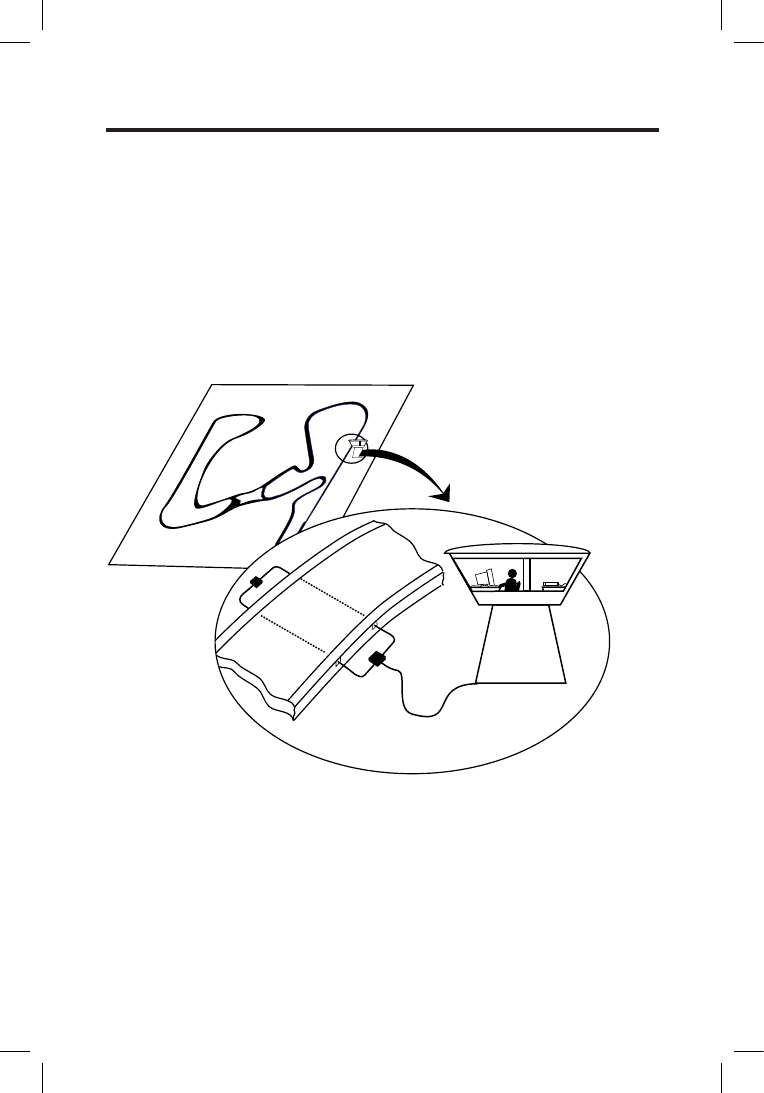
Figure 1.1 System overview
A:Loop
B:Connection Box
C:Computer
D: TnetX Pro Host
E:Loop End Box
A
ECD
B
4
2: Installation of the detection loop
To install the TnetX Pro system, one needs to install one
or more detection loops, connect the host and mount the
communicator to the car/motorcycle. For optimal results,
please follow the instructions as described carefully. Appendix
B contains a list of useful tools for installing the detection
loop.
2.1 Positioning
All wiring of the detection loop must be installed according to
the drawing below in order to avoid a serious degradation in
the performance of the system.
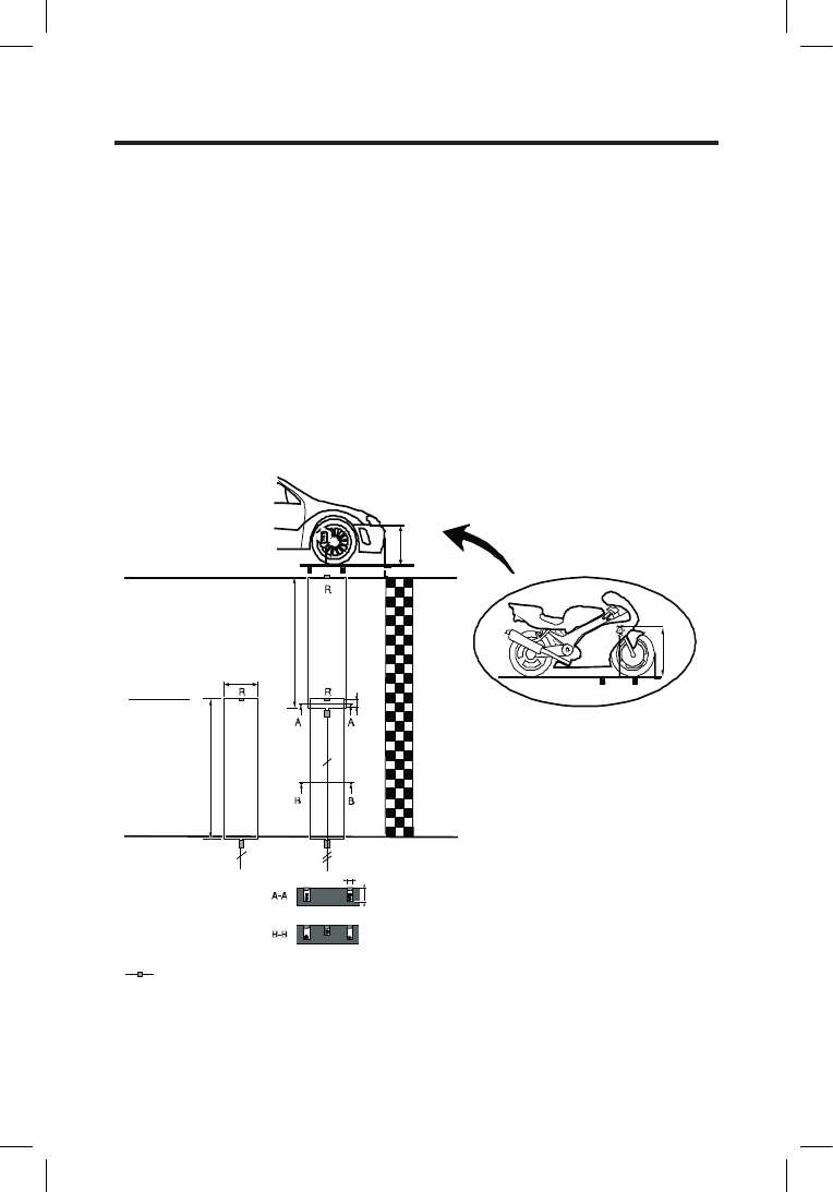
Figure 2.1 Detection loop installation overview
Trackwidth
20 m
Trackwidth
10 m
Max 10m
(33 ft)
60 cm (2 ft)
Max 10m
(33 ft)
3 mm (1/8")
15 - 20 mm (5 /8" - 3/4")
R=Termination box (470 Ohm, 0, 25 Watt resistor)
10 cm
(4")
max. 60 cm (2ft)
max.
120 cm
(4 ft)

5
a) The detection loop must be positioned in such a way
that the communicator is above the center of the
detection loop when the front of the cars/motorcycle
crossesthenishline.Makesurecars/motorcycle
cannot pass outside the detection loop. Extend the
detection loop outside the track if necessary.
b) One loop can be used for a track width of max. 10m
(33ft). For wider tracks use 2 or 3 (max.) loops. When
2 or 3 detection loops need to be installed, make
them of even length with 10 cm (4”) overlap.
c) With a seperate loop in the pitlane, connected to
the BNC connector marked, loop 3 (PIT) on the
host, passings registered in the pit lane can be
identiedassuchbythehost.
d) The detection loop is sensitive to interference,
sometimes emitted by nearby cables. When possible,
keep other cables 5 m (15 ft) away. Also, make sure
cars/motorcycles or other parts on the track will not
get closer than 5 m (15 ft) to the detection loop, to
avoid false inputs.
e) For dirt tracks, the detection loop is best installed in
plastic conduits at a maximum of 30cm (1ft) below
the surface. The maximum depth should be
chosen in a way that the cars/motorcycles
cannot dig out the detection loop. However please
respect the maximum distance between loop and
communicator, which is 60cm (2ft) for cars and 120cm
(4ft) for motorcycles.
LEARNED BY EXPERIENCE
When pulling the detection loop wire through the plastic
conduit, it is a good idea to pull another non-metal wire
through. This wire then can be used to install a new loop wire
in case it gets damaged.
6
2.2 Installation of the detection loop
a) Cut the slots in the track a maximum of 2 cm (3/4 in)
deep and 60 cm (2 ft) apart. Make sure the slots are
clean and dry. This will ensure a perfect seal when
the silicon is applied after the installation of
the wiring.
Put the wires of the detection loop in the slots and cut
the excess length of the detection loop wires.
b) Widen the slot with a chisel where the small
connection box of the loop is to be installed. Place the
connection box vertically.
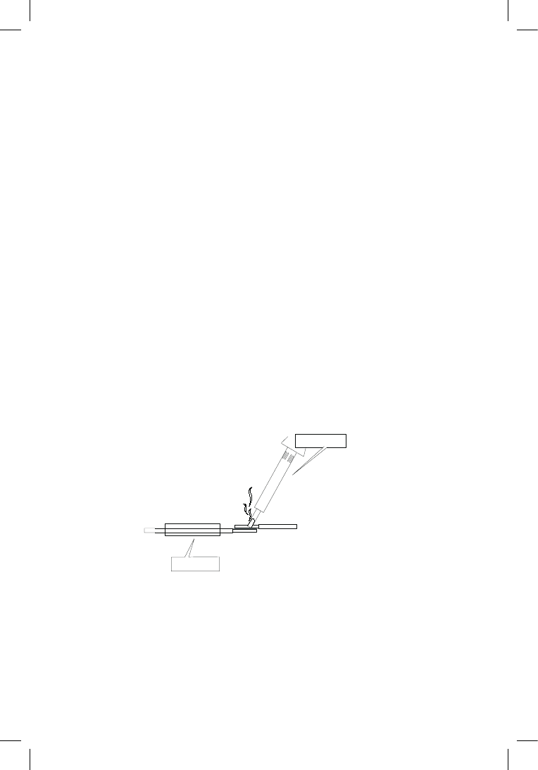
c) When all wires are installed, put the heat shrinkage
sleeve over a detection loop wire end. Then solder the
loop wire to the short wire end of the connection
box. When soldering the wires together, the solder
shouldowthroughtheentireconnectionand
not only around it. Now put the shrinkage sleeve over
the soldered connection and hold it over a heat
source to shrink the sleeve (also see the drawing
below). Repeat this procedure for the second wire
of the detection loop.
Figure 2.2 Solder the loop wire end
d) Fill the slot with silicone. Before doing this,
please test the loop as described in section 2.3.
Makesurenottooverlltheslotsandthatthesilicone
is fully under the surface of the track, otherwise tires
may pull out the silicone.
Shrink sleeve
Soldering iron

7
If any silicone spills out of the slot, remove the excess
silicone by scraping the top with a small piece of
cardboard. This also ensures that the silicone is
pressed into the slot for a perfect seal.
LEARNED BY EXPERIENCE
If you wish, you may pad the slots with backing rod or nylon
cord before sealing the slot with silicone. This helps to prevent
the excessive use of silicone and is also useful when pulling
out the silicone if the detection loop has to be replaced.
Silicone
There is a wide variety of silicone types available in hardware
stores; it is important that the right type is used. Silicone that
can withstand different temperatures as well as both wet and
dry conditions (since weather situations can vary ), should
beused.Ifyouareunsure,checkthespecicationsofthe
silicone.
The following types of silicone have been shown to yield
lasting results and are recommended by AMB:
• DowCorning890SLisaself-levelingsiliconekit.Itis
appliedasaliquidandllstheslotcompletely.
• Purexisapolyurethane-basedsiliconethatretains
its elasticity under a wide range of temperatures.

8
2.3 Testing the detection loop installation
Once the loop has been installed, it should be tested to ensure
that it is functioning correctly. We also recommend repeating
the same procedure at the start of each race event. You can
determine if your loop is functioning correctly by doing the
following tests:
a) Connect the detection loop to the host and
computer running AMB i.t. timing software (also see
the seperate TnetX Pro Host manual).
Check the background noise, which is updated every
vesecondsintheAMBi.t.timingsoftware.The
background noise level should be between 0 and 40
points. A higher value may indicate interference
by other electrical equipment in the area or a bad
loop installation.
Try switching off any suspected equipment or
removing nearby objects and check for improvements.
Especially at night, short-wave radio transmitters may
cause an increased background noise.
b) If a detection loop has been correctly installed, a
communicator should be picked up at the same
distance along the entire detection loop. To test this,
stand at one end of the detection loop about 8 m (25
ft) away and hold a communicator approximately 120
cm (4 ft) off the ground. Walk slowly towards
the detection loop. The ‘loop’ sign at the display will
lledinwhenthecommunicatorisdetected.Mark
the spot where the communicator was detected.
Repeat the process for the middle and other end of
the detection loop and do the same coming from the
other direction. The detection distance from the loop
should be approximately the same for all positions (<
20% variation).

9
c) Check the signal strengths of the communicators as
they are picked up by the system during a test with
motorcycles (also see paragraph 3.1 Installation of the
communicator). A good loop will yield consistent
communicator signal strengths of at least 100 points
with a hit rate of at least 10 points. The hit
rate may vary depending on the speed
of the communicator passings (slower passings
yield higher hit counts), but the signal strength should
be consistent (< 10 points variation).
10
3.Communicator Installation/
Operation
3.1 Installation of the communicator
The communicator can be recharged in a single charger or 34-
position charger case.
Positioning the communicator
The position of the communicator must be identical on all cars
or motorcycles competing in the race. Fix the communicator
vertically, max. 60cm (2ft) above the track for cars and 120cm
(4ft) for motorcycles. Make sure that the communicator has a
clearviewtothetrackwithnometalorcarbonberbeneath
it. Maximum operating temperature should not exceed
122F/50°C.
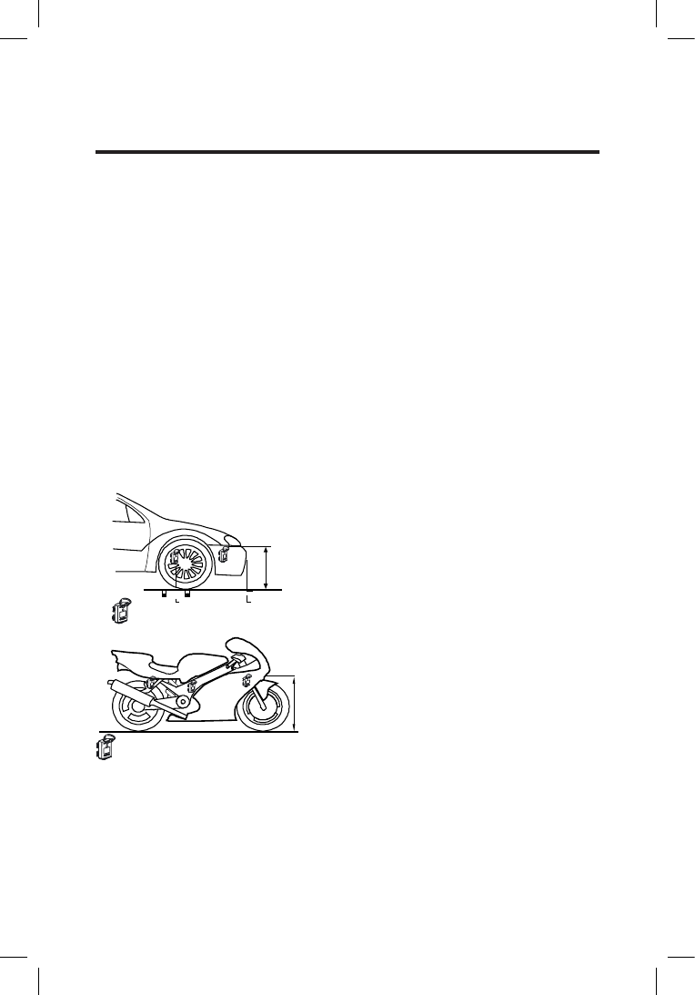
Figure 3.1 Communicator placement
Please note that: The
front wheel well is the
preferred position.
max.
120 cm (4ft)
max.
60 cm (2ft)
FinishLoop
Communicator placement options
Communicator placement options
11
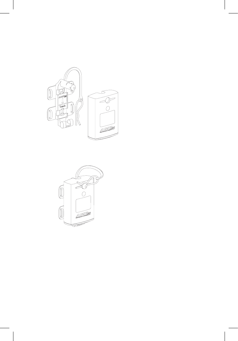
Installation of the communicator
Fixtheholderonthecar/motorcyclewiththexingrodontop
by using tie-wraps or screws. Fasten the communicator in the
holderusingthesuppliedxingpin.
Figure 3.2 Fastening the communicator in the holder
WARNING
A detached communicator can be very dangerous!
Make sure the communicator cannot get detached.
Use additional tie-wraps to secure the pin.
12
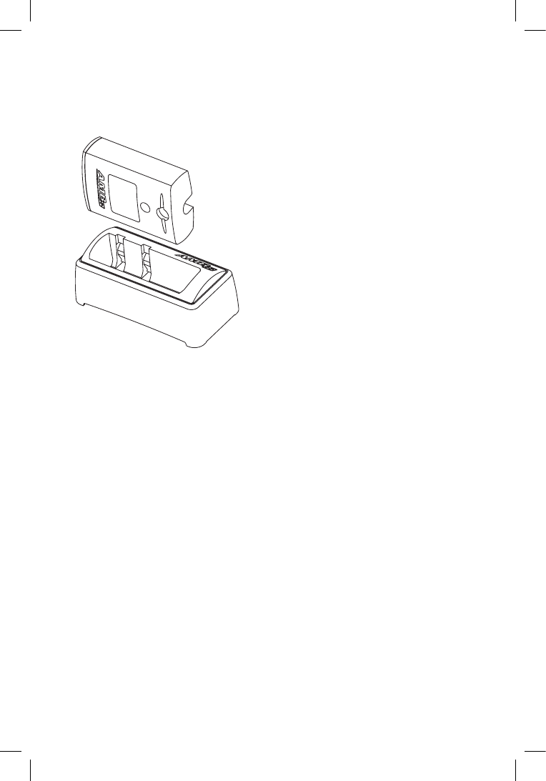
3.2 Charging instructions
Communicators can be charged in an individual charger or in
a charger case.
Figure 3.3 : Charging cradle
- Plug the power adapter into an electrical outlet
and place the communicator on the charging unit.
-Thecommunicator’sLedwillashredindicating
that the communicator is charging.
- After about 16 hours a steady green Led
indicates that the communicator is fully charged.
Afullchargeyieldsaminimumof5daysuse.TheLedashing
color and pattern indicates the remaining working days of
the communicator. See the next paragraph for the complete
information.
3.3 Led indication
The Led on the communicator provides the information of the
communicator status

13
LED Flashing color/pattern Description
Flashing …times green Minimum … days left before
the battery is empty
Flashing red (not in the charger) Less than 1 day of functioning
left
Continuously red The communicator stops work-
ing at any moment, charging is
required
No Light Communicator is discharged
Flashing red (in the charger) Communicator is charging
Continuous green (in the charger) Communicator fully charged
No Light (in unplugged charger) Communicator is in sleep
mode
Figure 3.4: Led indication
3.4 Sleep mode
The sleep mode is designed to turn off the communicator’s
signal and save battery life. It is necessary to use the
Sleep mode when travelling by airplane to adhere to airline
regulations. While in Sleep mode, the communicator’s charge-
discharge cycle will last up to 3 times longer.
Switching a communicator into sleep mode
A charged/functioning communicator can be put into a sleep
mode by placing it in an unpowered charging cradle or
charger case.
Switching the communicator back to normal mode
Normal functioning resumes when the communicator is
removed from the cradle or charger case.

14
3.5 Cleaning instructions
Over the course of time, communicator can become soiled
in various ways. Normal dirt can be removed from the
communicator with a soft brush and warm clean water up to
50°C. Cleaning electrical contacts: We recommend to spray
Isopropyl alcohol on the contacts of the communicator and on
the charger. Rub the contacts with ear sticks to clean them on
a regular basis.
Caution
MAKE SURE THE COMMUNICATOR IS DRY BEFORE
CHARGING.
CHARGE YOUR COMMUNICATOR ONCE EVERY 3 MONTHS.
DO NOT LEAVE THE COMMUNICATOR IN A POWERED
CHARGING CRADLE OR CHARGING RACK MORE THAN 24
HOURS.
DO NOT CLEAN COMMUNICATOR WITH AUTOMOTIVE
CLEANING PRODUCTS OR OTHER DETERGENTS.
DO NOT USE HIGH PRESSURE WATERGUNS OR OTHER
(DISH)WASHING MACHINES TO CLEAN OR RINSE THE
COMMUNICATOR.

15
Appendix A: Usefool tools/parts/
equipment
Useful Tools
- Multi meter (Range at least: 1 Ohm - 1 Mega Ohm)
- Wire cutter / stripper
- BNC Crimp tool for RG 58 & RG 59
- (Butane) Soldering gun
- Blade knife
- Coax stripper
- Screw driver (normal and Phillips)
Useful Spare Parts
- BNC couplers (3 pieces)
- BNC connectors (5 pieces) for yellow coax
- BNC connectors (5 pieces) for brown coax
- Shrink sleeves
- Spare loop (for tracks up to 20 m (65 ft) wide)
- Electrical tape
Additional Tool for new loop installations
- Chalk line to get a straight line on the track surface
- Caulk gun to apply silicone.
Please contact AMB i.t. if you would like to receive detailed
specicationsonanyoftheaboveitems.Youcanndour
contact details on page 2 of this manual.

16
Appendix B: Technical Specications
Communicator Lite
Numbers available : unlimited
Dimensions : 73x50x22 mm
(approx. 2.9x2x0.9”)
Weight : 100 g
Housing : Water- and shockproof
Max. speed : 260 km/h (160 mph)
Timing Resolution : 0,1 sec
Temperature range : 0 - 50 °C (32 - 122 °F)
Operating time : min. 5 days after full charge
Charge time : min. 16 hours for full charge
Charge indicator : LED indicates remaining
operating time in days
Signal transfer : magnetic induction
Communicator position : max. height cars 60 cm
(2ft), max. height
motorcycles 120 cm (4ft)
AMB Detection Loop
Track width : max. 20 m (65 ft)
Coax to TnetX Pro Host : max. 100 m (330 ft)
AMB Communicator Chargers
Individual charger : 12 VDC / 0.05 A
34 position charger case : 12 VDC / 1.0 A
Specicationsaresubjecttochangewithoutnotice.
17
Appendix C: CE and FCC Regulations
CE information:
This device complies with the EMC directive 89/336/EEC. A
copy of the declaration of conformity can be obtained at:
AMB i.t. BV
Zuiderhoutlaan 4
2012 PJ Haarlem
The Netherlands
FCC information:
This equipment complies with part 15 of the FCC rules.
Operation is subject to the following two conditions: (1) This
equipment may not cause harmful interference, and (2) this
equipment must accept any interference received, including
interference that may cause undesired operation.

18
Guarantiees & Warranties
AMB i.t. guarantees that, for a period of twenty four months from the date of dispatch,
hosts manufactured or sold by AMB i.t. with defects caused by faulty materials and/or
workmanship and/or design, will be repaired. If repair is not possible or economical for
AMB i.t., AMB i.t. has the choice to refund the purchase price of these goods or to deliver
new goods. AMB i.t.’s liability shall be strictly limited to replacing, repairing or issuing
credits at its option for any goods returned within twenty four months from the date of
dispatch. AMB i.t. shall not be liable for incidental or consequential damages including,
but not limited to costs of removal and reinstallation of goods, loss of goodwill, loss of
protsoruse.Iftherequirementssetforthaboveanddescribedbelowarenotcomplied
with, the AMB i.t. warranty/guarantee shall not apply and AMB i.t. shall be discharged
from all liability arising from the supply of defective goods.
EXCEPT AS EXPRESSLY PROVIDED IN THIS SECTION, AMB i.t. MAKES NO
REPRESENTATIONS OR WARRANTIES OF ANY KIND, NATURE OR DESCRIPTION,
EXPRESS OR IMPLIED, INCLUDING WITHOUT LIMITATION, ANY WARRANTY OR
MERCHANTABILITY, FITNESS OF THE GOODS FOR ANY PARTICULAR PURPOSE, OR
NONINFRINGEMENT, AND AMB i.t. HEREBY DISCLAIMS THE SAME.
Please see the AMB standard Terms and Conditions of Sale for the additional terms in
connection with the sale of goods and services covered by this manual.
Remedies and damages
AMB i.t. shall not incur any liability under the above warranty unless:
a) AMBi.t.ispromptlynotiedinwritingupondiscoverybythecustomerthat
such goods do not conform to the warranty and the appropriate invoice
number and date of purchase information is supplied;
b) The alleged defective goods are returned to AMB i.t. carriage pre-paid;
c) ExaminationbyAMBi.t.ofgoodsshallconrmthe
alleged defect exists and has not been caused by misuse, neglect, method of
storage, faulty installation, handling, or by alteration or accident.