Mackie 1202VLZ4 User Manual To The 5fb12854 092f 4c56 8ba1 4a2a20ed88e7
Mackie 1202VLZ4 Owner's Manual 1202vlz4_om Mackie - 1202VLZ4 - Owner's Manual
User Manual: Mackie 1202VLZ4 to the manual
Open the PDF directly: View PDF ![]() .
.
Page Count: 28
- Front Cover
- Important Safety Instructions
- Contents
- Features
- Introduction
- Getting Started
- Hookup Diagrams
- Patchbay Description
- 1. Mic Ins (Channels 1-4)
- Phantom Power
- 2. Line Ins (Channels 1-4)
- 3. Low Cut (Channels 1-4)
- 4. Gain (Channels 1-4)
- 5. Stereo Line Ins (Channels 5-6, 7-8, 9-10 and 11-12)
- 6. Imaginary Control
- Effects: Serial or Parallel?
- 7. Stereo Returns
- 8. Aux Send 1&2
- 9. Tape In
- 10. Tape Out
- 11. 1/4" Main Outs
- 12. Headphones Out
- 13. XLR Main Outs
- 14. XLR Main Out Level Switch
- 15. Control Room Outs
- 16. Alt 3-4 Outs
- 17. Channel Insert (Channels 1-4)
- 18. Power Connection
- 19. Fuse
- 20. Voltage Selector
- 21. Power Switch
- 22. Phantom Switch
- Channel Strip Description
- Output Section
- Appendix A: Service Information
- Appendix B: Connections
- Appendix C: Technical Information
- Warranty Statement
- Rear Cover

1202VLZ4
OWNER’S MANUAL
12-Channel Compact Mixer
POWER ON PHANTOM ON
CAUTION: TO REDUCE THE RISK OF FIRE
REPLACE WITH CORRECT TYPE FUSE. REMOVE
POWER CORD BEFORE CHANGING VOLTAGE.
100VAC 120VAC 240VAC
MIC
+4 4 3
4 / R 3 / L
CHANNEL INSERT
BAL / UNBAL
R L
CONTROL
ROOM
BAL / UNBAL
ALT
OUT
2 1
PRE-FADER / PRE EQ TIP SEND / RING RETURN
100-120V: 500mA/250 V SLO-BLO
220-240V: 250mA/250 V SLO-BLO
REPLACE WITH THE SAME TYPE FUSE AND RATING.
DISCONNECT SUPPLY CORD BEFORE CHANGING FUSE
UTILISE UN FUSIBLE DE RECHANGE DE MÊME TYPE.
DEBRANCHER AVANT DE REMPLACER LE FUSIBLE
MAIN
OUT LEVEL
MAIN
RIGHT
BALANCED
MAIN
LEFT
BALANCED
REVISION
SERIAL NUMBER
WARNING:
TO REDUCE THE RISK OF FIRE OR ELECTRIC
SHOCK, DO NOT EXPOSE THIS EQUIPMENT TO RAIN OR
MOISTURE. DO NOT REMOVE COVER. NO USER SERVICEABLE
PARTS INSIDE. REFER SERVICING TO QUALIFIED PERSONNEL.
AVIS:
RISQUE DE CHOC ELECTRIQUE — NE PAS OUVRIR
THIS DEVICE COMPLIES WITH PART 15 OF THE FCC RULES FOR THE U.S. AND THE ICES-003 FOR CANADA.
OPERATION IS SUBJECT TO THE FOLLOWING TWO CONDITIONS: (1) THIS DEVICE MAY NOT CAUSE HARMFUL
INTERFERENCE, AND (2) THIS DEVICE MUST ACCEPT ANY INTERFERENCE RECEIVED, INCLUDING INTERFERENCE
THAT MAY CAUSE UNDESIRED OPERATION.
2
1202VLZ4
1202VLZ4
Important Safety Instructions
1. Read these instructions.
2. Keep these instructions.
3. Heed all warnings.
4. Follow all instructions.
5. Do not use this apparatus near water.
6. Clean only with a dry cloth.
7. Do not block any ventilation openings. Install in accordance with the
manufacturer’s instructions.
8. Do not install near any heat sources such as radiators, heat registers,
stoves, or other apparatus (including amplifiers) that produce heat.
9. Do not defeat the safety purpose of the polarized or grounding-type
plug. A polarized plug has two blades with one wider than the other.
A grounding-type plug has two blades and a third grounding prong.
The wide blade or the third prong are provided for your safety. If the
provided plug does not fit into your outlet, consult an electrician for
replacement of the obsolete outlet.
10.
Protect the power cord from being walked on or pinched particularly at
plugs, convenience receptacles, and the point where they exit from the
apparatus.
11.
Only use attachments/accessories specified by the manufacturer.
12.
Use only with a cart, stand, tripod, bracket, or
table specified by the manufacturer, or sold with
the apparatus. When a cart is used, use caution
when moving the cart/apparatus combination to
avoid injury from tip-over.
13.
Unplug this apparatus during lightning storms or
when unused for long periods of time.
14.
Refer all servicing to qualified service personnel. Servicing is required
when the apparatus has been damaged in any way, such as power-
supply cord or plug is damaged, liquid has been spilled or objects have
fallen into the apparatus, the apparatus has been exposed to rain or
moisture, does not operate normally, or has been dropped.
15.
This apparatus shall not be exposed to dripping or splashing, and no
object filled with liquids, such as vases or beer glasses, shall be placed
on the apparatus.
16.
Do not overload wall outlets and extension cords as this can result in a
risk of fire or electric shock.
17.
This apparatus has been designed with Class-I construction and must
be connected to a mains socket outlet with a protective earthing
connection (the third grounding prong).
18.
This apparatus has been equipped with a rocker-style AC mains power
switch. This switch is located on the rear panel and should remain
readily accessible to the user.
19.
The MAINS plug or an appliance coupler is used as the disconnect
device, so the disconnect device shall remain readily operable.
PORTABLE CART
WARNING
CAUTION AVIS
RISK OF ELECTRIC SHOCK. DO NOT OPEN
RISQUE DE CHOC ELECTRIQUE. NE PAS OUVRIR
CAUTION: TO REDUCE THE RISK OF ELECTRIC SHOCK DO NOT REMOVE COVER (OR BACK)
NO USER-SERVICEABLE PARTS INSIDE. REFER SERVICING TO QUALIFIED PERSONNEL
ATTENTION: POUR EVITER LES RISQUES DE CHOC ELECTRIQUE, NE PAS ENLEVER LE COUVERCLE.
AUCUN ENTRETIEN DE PIECES INTERIEURES PAR L'USAGER.
CONFIER L'ENTRETIEN AU PERSONNEL QUALIFIE.
AVIS: POUR EVITER LES RISQUES D'INCENDIE OU D'ELECTROCUTION, N'EXPOSEZ PA S CET ARTICLE
A LA PLUIE OU A L'HUMIDITE
The lightning flash with arrowhead symbol within an equilateral triangle is
intended to alert the user to the presence of uninsulated "dangerous
voltage" within the product's enclosure, that may be of sufficient magnitude
to constitute a risk of electric shock to persons.
Le symbole éclair avec point de flèche à l'intérieur d'un triangle équilatéral
est utilisé pour alerter l'utilisateur de la présence à l'intérieur du coffret de
"voltage dangereux" non isolé d'ampleur suffisante pour constituer un risque
d'éléctrocution.
The exclamation point within an equilateral triangle is intended to alert the
user of the presence of important operating and maintenance (servicing)
instructions in the literature accompanying the appliance.
Le point d'exclamation à l'intérieur d'un triangle équilatéral est employé
pour alerter les utilisateurs de la présence d'instructions importantes pour le
fonctionnement et l'entretien (service) dans le livret d'instruction
accompagnant l'appareil.
20. NOTE: This equipment has been tested and found to comply
with the limits for a Class B digital device, pursuant to part 15
of the FCC Rules. These limits are designed to provide reasonable
protection against harmful interference in a residential installation.
This equipment generates, uses, and can radiate radio frequency
energy and, if not installed and used in accordance with the
instructions, may cause harmful interference to radio communications.
However, there is no guarantee that interference will not occur
in a particular installation. If this equipment does cause harmful
interference to radio or television reception, which can be determined
by turning the equipment off and on, the user is encouraged to try to
correct the interference by one or more of the following measures:
• Reorientorrelocatethereceivingantenna.
• Increasetheseparationbetweentheequipmentandthe
receiver.
• Connecttheequipmentintoanoutletonacircuitdifferentfrom
that to which the receiver is connected.
• Consultthedealeroranexperiencedradio/TVtechnicianfor
help.
CAUTION: Changes or modifications to this device not expressly
approved by LOUD Technologies Inc. could void the user's authority to
operate the equipment under FCC rules.
21.
This apparatus does not exceed the Class A/Class B (whichever is
applicable)
limits for radio noise emissions from digital apparatus as
set out in the radio interference regulations of the Canadian Department
of Communications.
ATTENTION — Le présent appareil numérique n’émet pas de bruits
radioélectriques dépassant las limites applicables aux appareils
numériques de class A/de class B (selon le cas) prescrites dans le
réglement sur le brouillage radioélectrique édicté par les ministere des
communications du Canada.
22.
Exposure to extremely high noise levels may cause permanent hearing
loss. Individuals vary considerably in susceptibility to noise-induced
hearing loss, but nearly everyone will lose some hearing if exposed to
sufficiently intense noise for a period of time. The U.S. Government’s
Occupational Safety and Health Administration (OSHA) has specified
the permissible noise level exposures shown in the following chart.
According to OSHA, any exposure in excess of these permissible limits
could result in some hearing loss. To ensure against potentially
dangerous exposure to high sound pressure levels, it is recommended
that all persons exposed to equipment capable of producing high
sound pressure levels use hearing protectors while the equipment
is in operation. Ear plugs or protectors in the ear canals or over the
ears must be worn when operating the equipment in order to prevent
permanent hearing loss if exposure is in excess of the limits set forth
here:
Duration,
per day in
hours
Sound Level
dBA, Slow
Response
Typical Example
8 90 Duo in small club
6 92
4 95 Subway Train
3 97
2 100 Veryloudclassicalmusic
1.5 102
1 105 Matt screaming at Troy about
deadlines
0.5 110
0.25 or less 115 Loudest parts at a rock concert
WARNING — To reduce the risk of fire or electric shock, do not
expose this apparatus to rain or moisture.
Correct disposal of this product. This symbol indicates that this product should not be disposed of with your household waste, according to the WEEE Directive (2012/19/EU) and your national law. This product
should be handed over to an authorized collection site for recycling waste electrical and electronic equipment (EEE). Improper handling of this type of waste could have a possible negative impact on the environment and
human health due to potentially hazardous substances that are generally associated with EEE. At the same time, your cooperation in the correct disposal of this product will contribute to the effective usage of natural
resources. For more information about where you can drop off your waste equipment for recycling, please contact your local city office, waste authority, or your household waste disposal service.

3
Owner’s Manual
Owner’s Manual
Part No. SW0970 Rev. B 08/14
©2014 LOUD Technologies Inc.
All Rights Reserved.
Contents
CHANNEL STRIP DESCRIPTION ............................... 13
“U” LIKE UNITY GAIN ............................. 13
23. LEVEL .................................................... 13
24. PRE-FADER SOLO ................................... 13
25. MUTE/ALT 3–4 ...................................... 13
26. PAN....................................................... 14
CONSTANT LOUDNESS ! ! ! ...................... 14
3-BAND EQ ............................................ 14
27. LOW EQ ................................................. 14
28. MID EQ .................................................. 14
29. HI EQ ..................................................... 15
MODERATION DURING EQ ...................... 15
30. AUX 2 SEND .......................................... 15
31. AUX 1 SEND .......................................... 15
OUTPUT SECTION .................................................. 16
32. MAIN MIX ............................................. 16
33. CONTROL ROOM SOURCE MATRIX .......... 16
34. CONTROL ROOM/SUBMIX ..................... 16
A WORD ABOUT PRE-FADER SOLO (PFL) 17
35. RUDE SOLO LIGHT .................................. 17
36. ASSIGN TO MAIN MIX ............................ 17
37. METERS – MANY DISPLAYS IN ONE! ....... 17
38. PRE OR POST (AUX 1) ........................... 18
39. AUX 1 MASTER ...................................... 18
40. STEREO RETURNS ................................... 18
41. RETURN TO AUX 1 ................................. 19
JACK NORMALLING ................................ 19
APPENDIX A: SERVICE INFORMATION .................... 20
APPENDIX B: CONNECTIONS.................................. 20
APPENDIX C: TECHNICAL INFORMATION ................ 24
SPECIFICATIONS ............................................. 24
BLOCK DIAGRAM ............................................ 25
TRACK SHEET.................................................. 26
1202VLZ4 LIMITED WARRANTY ............................ 27
IMPORTANT SAFETY INSTRUCTIONS ........................ 2
CONTENTS .............................................................. 3
FEATURES ............................................................... 4
INTRODUCTION ...................................................... 4
HOW TO USE THIS MANUAL .................................... 4
GETTING STARTED ................................................... 5
HOOKUP DIAGRAMS............................................... 6
PATCHBAY DESCRIPTION ......................................... 8
1. MIC INS (CHANNELS 1–4) ........................ 8
2. LINE INS (CHANNELS 1–4) ........................ 8
3. LOW CUT (CHANNELS 1–4) ....................... 9
4. GAIN (CHANNELS 1–4) ............................ 9
5. STEREO LINE INS ...................................... 9
6. IMAGINARY CONTROL ............................ 9
EFFECTS: SERIAL OR PARALLEL? ................ 9
7. STEREO RETURNS ................................... 10
8. AUX SEND 1&2 ...................................... 10
9. TAPE IN ................................................. 10
10. TAPE OUT .............................................. 10
11. 1/4" MAIN OUTS ................................... 10
12. PHONES ................................................ 11
13. XLR MAIN OUTS ................................... 11
14. XLR MAIN OUT LEVEL SWITCH ................ 11
15. CONTROL ROOM OUTS ........................... 11
16. ALT 3–4 OUTS ........................................ 11
17. CHANNEL INSERT (CHANNELS 1–4 ) ........ 11
18. POWER CONNECTION ............................. 12
19. FUSE ...................................................... 12
20. VOLTAGE SELECTOR ................................ 12
21. POWER SWITCH ..................................... 12
22. PHANTOM SWITCH ................................ 12
Please write your serial number here for future
reference (i.e., insurance claims, tech support,
return authorization, make dad proud, etc.)
Purchased at:
Date of purchase:
Like us
Follow us
Watch our dang videos

4
1202VLZ4
1202VLZ4
Features
• 12-channelmixerfeaturingoursignature
high-headroom,low-noisedesign
• 4boutique-qualityOnyxmicpreamps
•Ultra-wide60dBgainrange
•128.5dBdynamicrange
•+22dBulineinputhandling
•Extendedfrequencyresponse
•Distortionunder0.0007%(20Hz-50kHz)
• ImprovedRFrejection,perfectforbroadcast
applications
• Phantompowerforcondensermics
• 12high-headroomlineinputs
• 3-bandEQ(80Hz,2.5kHz,12kHz)
• 18dB/oct75Hzlow-cutlteronmicinput
channels
• Auxsend,level,panandPFLsolooneach
channel
• StereoreturnforconnectingFXprocessor
orotherstereosource
• ALT3/4stereobusforaddedroutingexibility
• Controlroom/phonessourcematrix
• High-resolution12-segmentstereometers
• Sealedrotarycontrolresistdustandgrime
• “Built-Like-A-Tank”ruggedsteelchassiswith
powder-coatnish
• High-visibility,high-contrastcontrolsdeliver
convenient“at-a-glance”visualfeedback
• Rack-mountabledesignusinganoptionalrack
earkit
• Multi-voltagepowersupplyforworldwideuse
Introduction
The12-channel1202VLZ4deliverstheoutstanding
qualityofouragshipOnyxpreampsinacompactmixer
designwiththehigh-headroom/low-noiseperformance
yourprofessionalapplicationdemands.
Fromeveryinputtoeveryoutput,youcancounton
theindustry-provenperformanceyouexpectfroma
VLZmixer.Plus,itistruly“Built-Like-A-Tank”witha
ridiculouslyruggedsolid-steelchasisplushigh-contrast
controlsforultimatetactilecontrol.
Andwithfeatureslikeadedicatedcontrolroom
section,the1202VLZ4offersatruestepupinexibility
andperformancethat'sidealforyourprofessional
application.
How To Use This Manual
Aftertheintroduction,agettingstartedguidewill
helpyougetthingssetupfast.Thesearefollowedby
hookupdiagramswhichshowsometypicalsetups.
Nextisadetailedtouroftheentiremixer.
Thedescriptionsaredividedintosections,just
asyourmixerisorganizedintodistinctzones:
• Patchbay
• ChannelStrip
• OutputSection
Throughoutthesesectionsyou’llndillustrations
witheachfeaturenumberedanddescribedinnearby
paragraphs.
Thisiconmarksinformationthatiscritically
importantoruniquetothemixer.Foryourown
good,readthemandrememberthem.
Thisiconwillleadyoutosomeexplanations
offeaturesandpracticaltips.Theyusually
havesomevaluablenuggetsofinformation.
Need help with your mixer?
• Visit www.720trees.com and click Support to find: FAQs, manuals and other useful information.
• Email us at: techmail@loudtechinc.com.
• Telephone 1-800-898-3211 to speak with one of our splendid technical support chaps
(Monday through Friday, normal business hours, Pacific Time).

5
Owner’s Manual
Owner’s Manual
Getting Started
Werealizethatyoumustbereallykeentotryout
themixer.Pleasereadthesafetyinstructionsonpage
2,thenhavealookthroughsomeofthefeaturesand
detailsinthismanual.
Setup
Usethemixerinanicecleananddryenvironment,
freefromdryerlintanddustbunnies.
Zero the controls
1. Fullyturndownalltheknobstominimum,
exceptforthechannelEQandpancontrols,
whichshouldbecentered.
2. Makesureallbuttonsareintheoutposition.
Connections
1. MakesuretheACpowerswitchisoffbefore
makinganyconnections.
WARNING:BeforepluggingtheACpower
cordintothemixer,makesuretheVOLTAGE
SELECTORswitchissettothesamevoltage
asthelocalACmainssupply(seepage12).
2. PushthelinecordsecurelyintotheIEC
connectorontherearpanel,andplugitintoa
3-prongACoutlet.Themixermayaccept
any
ACvoltagerangingfrom100VACto240VAC.
3. Plugabalancedmicrophoneintooneofthemic
XLR(3-pin)connectors.Orconnectany
line-levelsignal(keyboard,orguitarpreamp)
toalineinputjackusingaTSoraTRS
1/4"plug.
4. Ifyourmicrophonerequiresphantompower,
turnonthe48Vphantompowerbutton.
5. Allmonochannelshaveinsertjacksthatcanbe
usedtoconnectanexternaleffectsordynamics
processorintothesignalchain.
6. Connectthemainoutputsofthemixer(either
XLRorTRS1/4")tothelinelevelinputsofyour
amplier(withspeakersalreadyattached)or
tothelinelevelinputsofpoweredspeakers.
Set the levels
It’snotevennecessarytohearwhatyou’redoingto
setoptimallevels.Butifyou’dliketo:Plugheadphones
intothephonesoutputjack,thenturnupthephones
knobjustalittle.
1. Turnonthemixerbypressingthetopedgeof
thepowerswitch.
2. Foronechannel,pressthesoloswitchin,and
therudesololightwillturnon.
3. Playsomethingintothatinputatreal-world
levels.
4. Adjustthatchannel'sgaincontroluntilthe
rightmainmeterstaysaroundthe0dBLED
(marked“levelset”)andnevergoeshigher
than“+7.”
5. Disengagethechannel'ssoloswitch.
6. Repeatsteps2to5fortheremainingchannels.
7. Turnupthechannellevelknobtothe“U”mark.
8. Slowlyturnupthemainmixknobuntilyou
hearthesignalsintheheadphones.
9. Ifneeded,applysomechannelEQwisely.
10.Adjustthechannellevelstogetthebestmix.
Keepthegaincontrolsandlevelsfullydownon
unusedchannels.
11.Duringtheperformance,ifyounoticeachannel
OLLEDturningonduringpeaks,carefullyturn
downthatchannel'sgaincontroluntilOLdoes
notturnon.
Things to Remember
• Neverlistentoloudmusicforprolonged
periods.PleaseseetheSafetyInstructionson
page2forinformationonhearingprotection.
• Alwaysturndownthephoneslevelwhen
makingconnections,pressingsolo,ordoing
anythingthatmaycauseloudnessinthe
headphones.Thiswillhelpprotectyour
hearing.
• Alwaysturndownthemainmixleveland
controlroom/submixlevelswhenmaking
connections
tothemixer.Betteryet,turnoffthepower.
• Whenshuttingdown,turnoffanypower
ampliersorpoweredspeakersrst.When
poweringup,turnthemonlast.Thiswill
reducethechanceofturn-onorturn-off
thumps.
• Savetheshippingbox!

6
1202VLZ4
1202VLZ4
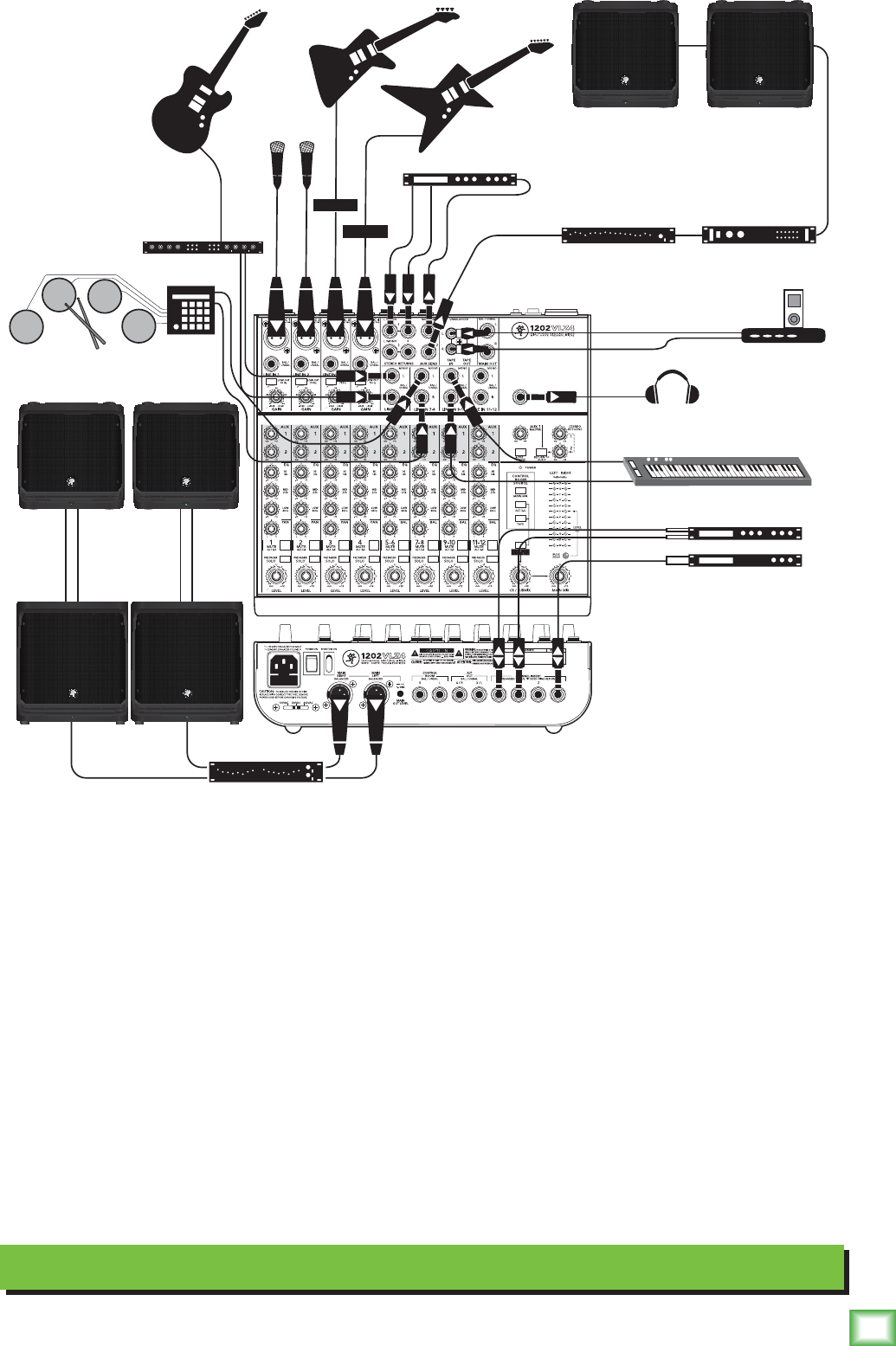
Hookup Diagrams
Condenser
microphones
Direct
Boxes
MR8mk3
studio monitors
Headphones
Headphone amp
Electronic Drum Kit
Stereo
Guitar
Effects
Synth
Stereo Compressor
Mono Compressor
Multi Effects Processor
Digital Delay
Laptop
Recording System
This diagram shows microphones connected to the mic inputs of channels 1 and 2, and a vocal
compressor connected to the channel 1 insert jack. Bass and electric guitars are attached to channels
3 and 4 via DI boxes with a stereo compressor on the insert. The lead guitar plays through a stereo
effects processor plugged into channels 5 and 6. An electronic drum kit is connected to channels 7
and 8, while a synth is connected to the line inputs of channels 9 and 10.
The audio outputs from a laptop computer are connected to the RCA tape inputs. This allows you to
playback your recordings made using the DAW of your choice. The Alt 3-4 outputs are used to feed the
inputs to your computer's sound card. By pressing a mute/alt 3-4 switch, it is easy to set up a channel to
record onto your computer.
A headphone amplifier is connected to the headphones output, and feeds four pairs of headphones
while a pair of MR8mk3 powered studio monitors are connected to the control room outputs.
You can use this setup to record overdub style:
1. For the track being recorded, route it to the alt 3-4 output, which feeds the computer input.
2. Monitor just the previously-recorded tracks through the tape input, which will feed the control
room/phones.
3. Since only the currently-recorded track is feeding the computer (through alt 3-4), you will hear the
previous tracks you are overdubbing to, but they will not be recorded to each new track.
4. The control room/phones is fed by a mixture of alt 3-4 (currently recorded track) and tape in
(output of your DAW playing back previously-recorded tracks).
7
Owner’s Manual
Owner’s Manual
Condenser
microphones
Direct
Boxes
DLM12S subwoofers
Headphones
Electronic Drum Kit
Stereo
Guitar
Effects
Synth
Stereo Compressor
Mono Compressor
Multi Effects Processor
Mono Power Amplifier
Stereo
EQ
Mono EQ
DLM8 Stage Monitors
iPodTM
Docking Station
DLM8 loudspeakers
Live Stereo PA System
This diagram shows microphones connected to the mic inputs of channels 1 and 2, and a vocal
compressor connected to the channel 1 insert jack. Bass and electric guitars are attached to channels
3 and 4 via DI boxes with a stereo compressor on the insert. The lead guitar plays through a stereo
effects processor plugged into channels 5 and 6. An electronic drum kit is connected to channels 7
and 8, while a synth is connected to the line inputs of channels 9 and 10. An iPodTM docking station
is connected to the tape RCA inputs, so you can play pre-recorded music during the breaks.
A multi-effects processor is connected to aux send 1, with the aux send set to post-level. Effects are
added to the main mix via the stereo return inputs, and adjusted with the stereo return level control.
To use the aux send for stage monitors instead of an effects processor, set the aux to pre-level so the
monitor volume level can be adjusted independently from the main loudspeakers. This setup may easily
be configured to become a mono PA setup: (A) Stereo sources should feed the left mono side of the
channel input only, (B) pan each channel hard left, (C) connect the mono PA system to the left main out.
The main mix output connects to a stereo graphic EQ before connecting to a pair of DLM12S powered
subwoofers which are connected to a pair of DLM8 powered loudspeakers to please your audience.
8
1202VLZ4
1202VLZ4
Patchbay Description
1
2
3
4
5
Attheriskofstatingtheobvious,thisiswhereyou
plugeverythingin:microphones,line-levelinstruments
andeffects,headphones,andtheultimatedestination
foryoursound:PAsystem,DAW,etc.
SeeAppendixBforfurtherdetailsanddrawingsof
theconnectorsyoucanusewiththe1202VLZ4.Alsosee
thechannelstripdescriptiononpage13fordetailsof
thesignalroutingfromtheXLRandlineinputs.
1. Mic Ins (Channels 1–4)
ThisisafemaleXLRconnectorthatacceptsa
balancedmicorlinelevelinputfromalmostanytype
ofsource.TheseOnyxmicpreampsfeaturehigher
delityandheadroomrivalinganystandalonemic
preamponthemarkettoday.Thesecircuitsare
excellentatrejectinghumandnoise.
TheXLRinputsarewiredasfollows:
Pin1=Shieldorground
Pin2=Positive(+orhot)
Pin3=Negative(–orcold)
Professionalribbon,dynamic,andcondensermicsall
soundexcellentthroughtheseinputs.Themic/line
inputswillhandleanykindoflevelyoucantossat
them,withoutoverloading.
Microphone-levelsignalsarepassedthroughthe
mixer'ssplendidmicrophonepreamplierstobecome
line-levelsignals.
Noteveryinstrumentismadetoconnectdirectly
toamixer.GuitarscommonlyneedaDirectInjection
(DI)boxtoconnecttothemixer'smicinputs.These
boxesconvertunbalancedline-levelsignalsfromyour
guitar,intobalancedmic-leveloutputs,andprovide
signalandimpedancematching.Theyalsoletyousend
yourgiftedguitarrenditionsoverlongcablesoraudio
snakes,withminimuminterferenceandhigh-frequency
signalloss.Askyourdealerorguitarmakerabouttheir
recommendationsforagoodDIbox.
Phantom Power
Mostmodernprofessionalcondensermicsare
equippedforphantompower,whichletsthemixer
sendlow-currentDCvoltagetothemic’selectronics
throughthesamewiresthatcarryaudio.(Semi-pro
condensermicsoftenhavebatteriestoaccomplishthe
samething.)“Phantom”owesitsnametoanabilityto
be“unseen”bydynamicmics(ShureSM57/SM58,for
instance),whichdon’tneedexternalpowerandaren’t
affectedbyitanyway.
The1202VLZ4’sphantompowerisgloballycontrolled
bythephantom[22]switchontherearpanel.(This
meansthephantompowerforchannels1-4isturnedon
andofftogether.)
Neverplugsingle-ended(unbalanced)
microphonesorinstrumentsintothemic[1]
inputjacksifthephantompowerison.
Donotpluginstrumentoutputsintothemic
inputjackswithphantompoweron,unless
youknowforcertainitissafetodoso.
2. Line Ins (Channels 1–4)
Thesefourline-inputssharecircuitry(butnot
phantompower)withthemicpreamps,andcanbe
drivenbybalancedorunbalancedsourcesatalmost
anylevel.
Toconnectbalancedlinestotheseinputs,usea1⁄4"
Tip-Ring-Sleeve(TRS)plug,wiredasfollows:
Tip=Positive(+orhot)
Ring=Negative(–orcold)
Sleeve=Shieldorground
Toconnectunbalancedlinestotheseinputs,usea
1⁄4"mono(TS)phoneplug,wiredasfollows:
Tip=Positive(+orhot)
Sleeve=Shieldorground
Thelineininputs1–4areagoodplacetoconnect
olderinstrumentsthatneedmoregain.Youcancorrect
weaklevelsbyadjustingthecorrespondingchannel’s
gain control.

9
Owner’s Manual
Owner’s Manual
5. Stereo Line Ins
(Channels 5–6, 7–8, 9–10 And 11–12)
Thesefullybalancedinputsaredesignedforstereo
ormono,balancedorunbalancedsignals,from–10dBV
to+4dBu.Theycanbeusedwithjustaboutany
professionalorsemi-proinstrument,effectorCDplayer.
Inthestereoaudioworld,anodd-numbered
channelusuallyreceivesthe“leftsignal.”Forexample,
youwouldfeedthe1202VLZ4’slineinputs5-6astereo
signalbyinsertingthedevice’sleftoutputpluginto
thechannel5jack,anditsrightoutputplugintothe
channel6jack.
Whenconnectingamonodevice(justonecord),
alwaysusetheleft(mono)input(jacks5,7,9or11)
andplugnothingintotherightinput(jacks6,8,10or
12)—thiswaythesignalwillappearonbothsides.This
trickiscalled“jacknormalling.”
6. Imaginary Control
Thiscontrolispurelyagmentofourimagination.It
willcomeinhandyafterlonghoursofmixing,whenyou
reallywouldlikeanicecupoftea,avacationinHawaii,
oratriptotheouterreachesoftheSolarSystem.Thisis
thecontrolforyou.Bethankfulyouboughta1202VLZ4.
Weloveyou,man!
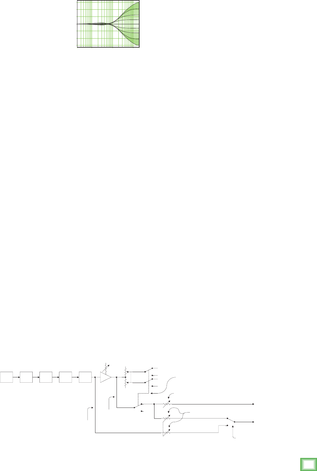
Effects: Serial Or Parallel?
Thenexttwosectionstosstheterms“serial”and
“parallel”aroundlikehackysacks.Here’swhatwemean
bythem:
“Serial”meansthattheentiresignalisroutedthrough
theeffectsdevice.Examples:compressor/limiters,
graphicequalizers.Line-levelsourcescanbepatched
throughaserialeffectsdevicebeforeorafterthemixer,
orpreferablythroughtheinsertjackslocatedonthe
rearpanel(channelinsert[17]send/return).
“Parallel”meansthataportionofthesignalinthe
mixeristappedofftothedevice(auxsend),processed
andreturnedtothemixer(stereoreturn)tobemixed
withtheoriginal“dry”signal.Thisway,multiple
channelscanallmakeuseofthesameeffectsdevice.
Examples:reverb,digitaldelay.
Dry Signal Processed
Signal
Insert
Send Insert
Return
Dry Signal(s) Dry Signal(s)
Aux
Send Aux
Return
Wet Signal
Channel Path
Mix
Stage
Output
Section
Processed
Signal
Signal Processor
(e.g., Compressor)
Signal Processor
(e.g., Reverb)
Dry Signal Processed
Signal
Insert
Send Insert
Return
Dry Signal(s) Dry Signal(s)
Aux
Send Aux
Return
Wet Signal
Channel Path
Mix
Stage
Output
Section
Processed
Signal
Signal Processor
(e.g., Compressor)
Signal Processor
(e.g., Reverb)
3. Low Cut (Channels 1–4)
Eachlowcutswitch,oftenreferredtoasahighpass
lter(alldependsonhowyoulookatit),cutsbass
frequenciesbelow75Hzatarateof18dBperoctave.
Werecommendthatyouuselow-cutonevery
microphoneapplicationexceptkickdrum,bassguitar,
orbassysynthpatches.Theseaside,thereisn’tmuch
downtherethatyouwanttohear,andlteringitout
makesthelowstuffyoudowantmuchmorecrispand
tasty.Notonlythat,butlow-cutcanhelpreducethe
possibilityoffeedbackinlivesituations,andithelps
toconserveamplierpower.
Anotherwaytoconsiderlow-cut’sfunction
isthatitactuallyaddsexibilityduringlive
performances.Withtheadditionoflow-cut,
youcansafelyuselowequalizationonvocals.
Manytimes,bassshelvingEQcanreallybenet
voices.Troubleis,addinglowEQalsoboostsstage
rumble,michandlingclunksandbreathpops.
Applyinglow-cutremovesallthoseproblems,so
youcanaddlowEQwithoutblowingyoursubwoofers.
Here’swhatthecombinationoflowEQandlow-cut
lookslikeintermsoffrequencycurves:
4. Gain (Channels 1–4)
Ifyouhaven’talready,pleasereadthelevel-setting
procedureonpage5.
Gainadjuststheinputsensitivityof
themicandlineinputsconnected
tochannels1through4.Thisallows
signalsfromtheoutsideworldtobe
adjustedtooptimalinternaloperating
levels.
IfthesignaloriginatesthroughtheXLRjack,there
willbe0dBofgainwiththeknobfullydown,rampingto
60dBofgainfullyup.
Throughthe1⁄4"input,thereis20dBofattenuation
fullydownand40dBofgainfullyup,witha“U”(unity
gain)markat10:00.This20dBofattenuationcanbe
veryhandywhenyouareinsertingaveryhotsignal,or
whenyouwanttoaddalotofEQgain,orboth.Without
this“virtualpad,”thisscenariomightleadtochannel
clipping.
Low Cut with Low EQ
20
Hz
100
Hz
1k
Hz
10k
Hz
20k
Hz
–15
–10
–5
0
+5
+10
+15
20
Hz
100
Hz
1k
Hz
10k
Hz
20k
Hz
–15
–10
–5
0
+5
+10
+15
Low Cut

10
1202VLZ4
1202VLZ4
7. Stereo Returns
Thisiswheretoconnecttheoutputsofparallel
effectsdevices(orextraaudiosources).These
balancedinputsaresimilartothestereolinein[2]
inputs(withoutEQ,auxsends,pan,mute,andsolo).
Thecircuitswillhandlestereoormono,balancedor
unbalancedsignals,eitherinstrumentlevel,–10dBV
or+4dBu.Theycanbeusedwithjustaboutanypro
orsemiproeffectsdeviceonthemarket.Thesignals
comingintotheseinputscanbeadjustedusingthe
stereoreturn[40]knobsbeforepassingontothe
mainmixbus,seepage19.
Onedevice:ifyouhavejustoneparalleleffectsdevice
(twocords),usestereoreturn1andleavestereoreturn
2unplugged.thatway,theunusedstereoreturn2level
controlcanbeusedtofeedstereoreturn1toyourstage
monitors,viathereturntoaux1[41]switch.
Monodevice:ifyouhaveaneffectsdevicewitha
monooutput(onecord),plugthatintostereoreturn1,
l/mono,andleavestereoreturn1,right,unplugged.
Thiswaythesignalwillbesenttobothsides,magically
appearinginthecenterasamonosignal.Thiswon’t
workwithstereoreturn2—you’llneedaY-cord.
8. Aux Send 1&2
Theauxsend[31]knobstapaportionofeach
channel'ssignaltoprovideanoutputheretofeed
externalparalleleffectsprocessorsorstagemonitoring.
Seetheauxsenddetailsonpage15.
These1⁄4"jacksarebalancedoutputscapable
ofdelivering22dBuintoa600ohmbalancedor
unbalancedload.
9. Tape In
TheseRCAjacksaredesignedtoworkwithsemipro
aswellasprorecorders.Tocompensatefortypically
lowlevels,signalscominginherewillbeautomatically
boostedby6dB.
Connectyourtaperecorder’soutputshere,using
standardhi-(RCA)cables.
Usethesejacksforconvenienttapeplaybackofyour
mixes.You’llbeabletoreviewamixandthenrewind
andtryanotherpasswithoutrepatchingordisturbing
themixerlevels.Youcanalsousethesejackswith
aportableCDplayertofeedmusictoaPAsystem
betweensets.
WARNING:Engagingboththetapeandassign
tomainmixbuttonsinthecontrolroom
source[33]matrixcancreateafeedback
pathbetweentapeinputandtapeoutput.Makesure
yourtapedeckisnotinrecord,record-pause,orinput
monitormode,whenyouengagetheseswitches,or
makesurethecontrolroom/submix[34]levelknob
isfullycounterclockwise(off).
10. Tape Out
TheseunbalancedRCAconnectionstapthemain
mixoutputtomakesimultaneousrecordingandPA
workmoreconvenient.Connectthesetoyourrecorder’s
inputs.(Seealsomainmix[32]onpage16.)
Monoout:Ifyouwanttofeedamonosignaltoyour
tapedeckorotherdevice,simplyuseanRCAY-cordto
combinetheseoutputs.Donotattemptthiswithany
otheroutputsonthe1202VLZ4.
11. 1/4" Main Outs
The1/4"TRSoutputconnectorsprovidebalancedor
unbalancedline-levelsignals.Connectthesetothenext
deviceinthesignalchainlikeanexternalprocessor
(compressor/limiter),ordirectlytotheinputsofthe
mainamplier.Thesearethesamesignalthatappears
attheXLRmainoutputs[13],but6dBlowerwhenthe
XLRisusedbalanced.
Toconnectbalancedlinestotheseinputs,usea1⁄4"
Tip-Ring-Sleeve(TRS)plug,wiredasfollows:
Tip=Positive(+orhot)
Ring=Negative(–orcold)
Sleeve=Shieldorground
Toconnectunbalancedlinestotheseinputs,usea
1⁄4"mono(TS)phoneplug,wiredasfollows:
Tip=Positive(+orhot)
Sleeve=Shieldorground
789 10 11
12

11
Owner’s Manual
Owner’s Manual
Thesebalancedoutputsarecapableofdelivering22
dBuintoa600ohmbalancedorunbalancedload.
16. Alt 3–4 Outs
These1⁄4"outputsarethesumofanychannelsthat
havethemute/alt3-4[25]switchpressedin(seepage
13forthetenderdetails).
Thesebalancedoutputsarecapableofdelivering
22dBuintoabalancedorunbalancedload.
17. Channel Insert (Channels 1–4)
Theserear-paneljacksarewhereyouconnectserial
effectssuchascompressors,equalizers,de-essers,
orlters.Sincemostpeopledon’thavemorethana
fewofthesegadgets,we’veincludedinsertsforjust
therstfourchannels.Ifyouwanttousethiskind
ofprocessingonchannels5through12,simplypatch
throughtheprocessorbeforeyoupluginto
the1202VLZ4.
Thechannelinsertpointsareafterthegain[4]
andlowcut[3]controls,butbeforethechannel’s
EQ[27]andlevel[23]controls.Thesend(tip)is
low-impedance(120ohms),capableofdrivingany
line-leveldevice.Thereturn(ring)ishigh-impedance
(over2.5kohms)andcanbedrivenbyalmostany
device.
SeeAppendixBfordetailsanddrawingsaboutinsert
cables,andadiagramshowingthreewaystousethe
jacks.
Besidesbeingusedforinsertingexternaldevices,
thesejackscanalsobeusedaschanneldirectoutputs;
post-gain,post-lowcut,andpreEQ.Infact,ourOnyx
micpreampshavebecomesofamous,thatpeoplebuy
thesemixersjusttohavefouroftheseintheirarsenal.
tip
This plug connects to one of the
mixer’s Channel Insert jacks. ring
tip ring
sleeve
SEND to processor
RETURN from processor
(TRS plug)
12. Headphones Out
Thisstereojackwilldriveanystandardheadphone
toveryloudlevels.Tolearnhowsignalsarerouted
totheseoutputs,seesourcematrix[33]onpage16.
Ifyou’rewiringyourowncableforthephonesoutput,
followstandardconventions:
Tip=Leftchannel
Ring = Right channel
Sleeve=Commonground
WARNING:Whenwesaytheheadphone
ampisloud,we’renotkidding.Itcancause
permanenteardamage.Evenintermediate
levelsmaybepainfullyloudwithsomeearphones.
BE CAREFUL! Alwaysturnthectlroom/submix[34]
knoballthewaydownbeforeconnectingheadphones.
Keepitdownuntilyou’veputthephoneson.Thenturn
itupslowly.Why?“Engineerswhofrytheirearsnd
themselveswithshortcareers.”
13. XLR Main Outs
Usethesetosendthemainmixoutintotheline-level
balancedinputsofyouramplierorpoweredspeakers.
Theselow-impedanceoutputsarefullybalanced
andcapableofdriving+4dBulineswithupto28dB
ofheadroom.Thisoutputis6dBhotterthanother
outputs.
14. XLR Main Out Level Switch
Engagingthisswitchreducesthelevelofthe
balancedXLRmainoutputsby40dB,soyoucan
feedthemicrophoneinputof,say,anothermixer.
(YoucansafelyconnecttheXLRoutputsintoan
inputthatprovides48Vphantompower.)
15. Control Room Outs
These1⁄4"outputsareprovidedsoyoucanlisten
tosomethingotherthanthemainmix.Thesource
isselectedusingthesourcematrix[33]switches
(seepage16).Youcanchoosetolistentothemainmix,
thealt3-4stereobus(seemute/alt3-4onpage13),
soloedchannels,orthetapeinput.Thevolumeis
adjustablewiththecontrolroom/submix[34]knob.
13
14 15 16 17
12
1202VLZ4
1202VLZ4
18. Power Connection
Justincaseyoulosethecordprovidedwiththe
1202VLZ4,itspowerjackacceptsastandard3-prong
IECcordlikethosefoundonmostprofessional
recorders,musicalinstruments,andcomputers.
WARNING:BeforepluggingtheACpower
cordintothe1202VLZ4,makesurethat
thevoltageselector[20]slideswitchis
settothesamevoltageasthelocalACmainssupply.
WARNING:Disconnectingtheplug’sground
pincanbedangerous.Don’tdoit.
19. Fuse
The1202VLZ4isfusedforyour(anditsown)
protection.Ifyoususpectablownfuse,disconnect
theACmainspowercord,pullthefusedrawerout
(locatedjustbelowthecordreceptacle)andreplace
thefusewitha500mA(0.5amps)SLOBLO5x20mm,
availableatelectronicsstoresoryourdealer.Usea
250mAfuseifthelocalvoltageis220-240VAC.
Iftwofusesblowinarow,somethingisverywrong.
Pleasecallourtoll-freenumber1-800-898-3211from
withintheU.S.(orthedistributorinyourcountry)and
ndoutwhattodo.
20. Voltage Selector
WARNING:BeforepluggingtheACpower
cordintothe1202VLZ4,makesurethatthe
voltageselector[20]slideswitchissettothe
samevoltageasthelocalACmainssupply.Onlyslide
thevoltageswitchwiththepowercordunplugged.
Useaatheadedscrewdrivertoslidetheswitch
ifneeded.Theswitchallowsyoutousethemixer
indifferentcountriesandvoltages,meetinteresting
peoplefromothercultures,andentertainthemwith
youruniqueblendofRockabillyFunkadeliaThrash
Metal.
21. Power Switch
Pressthetopofthisrockerswitchinwardstoturnon
themixer.ThepowerLEDonthetopsurfaceofthemix-
erwillglowwithhappiness,oratleastitwillifyouhave
themixerpluggedintoasuitableliveACmainssupply.
Pressthebottomofthisswitchtoputthemixerinto
standbymode.Itwillnotfunction,butthecircuitsare
stilllive.ToremoveACpower,eitherturnofftheACmains
supply,orunplugthepowercordfromthemixerandthe
ACmainssupply.
Asageneralguide,youshouldturnthemixeronrst,
beforethepoweramplierorpoweredspeakers,and
turnitofflast.Thiswillreducethepossibilitiesofany
turn-on,orturn-offthumpsinyourspeakers.
22. Phantom Switch
Thisglobalrockerswitchcontrolsthephantompower
supplyforcondensermicrophonespluggedintochannel
mic[1]inputs(seepage8).
Pressthetopoftheswitchinwardstoengage
phantompowertothefourmicinputs.Pressthe
bottomoftheswitchtoturnitoff.
Whenturnedon(oroff),thephantompower
circuitrytakesafewmomentsforvoltagetoramp
up(ordown).Thisisperfectlynormal.Justlikeme.
Oh,andmyimaginaryfriendLazlowhohelpsmewrite
allthemanuals.SayhellotothenicefolksLazlo.
18
19
21 22
20
13
Owner’s Manual
Owner’s Manual
Channel Strip Description
checkoutwhataparticularchannelisuptoanytime
duringasession.Youcansoloasmanychannelsat
atimeasyoulike.
Soloisalsothekeyplayerinthelevel-setting
procedureonpage5.
Soloedchannelsaresenttothesourcemix,which
ultimatelyfeedsyourcontrolroom,phonesandmeter
display.Wheneversoloisengaged,allsourceselections
(mainmix,alt3-4andtape)aredefeated,toallowthe
soloedsignaltodojustthat—solo!
WARNING: Pre-fadersolotapsthe
channelsignalbeforethelevelknob.
Ifyouhaveachannel’slevelknobsetbelow
“U”(unitygain),solowon’tknowthatandwillsend
aunitygainsignaltothecontrolroom,phonesand
meterdisplay.Thatmayresultinastartlinglevelboost
attheseoutputs.
25. Mute/Alt 3–4
Thedual-purposemute/alt3–4busisoursignature.
WhenGregwasdesigningourrstproduct,hehadto
includeamuteswitchforeachchannel.Muteswitches
dojustwhattheysoundliketheydo.Theyturnoffthe
signalby“routing”itintooblivion.“Gee,whatawaste,”
Gregreasoned.“Whynothavethemutebuttonroutethe
signalsomewhereelseuseful…likeaseparatestereo
bus?”Somute/alt3–4reallyservestwofunctions—
muting(oftenusedduringamixdownorliveshow),and
signalrouting(formultitrackandlivework)whereit
actsasanextrastereobus.
Tousethisasamuteswitch,allyouhavetodois
notusethealt3–4[16]outputs.Then,wheneveryou
pressthisswitch,youwillassignachanneltothese
unusedoutputs,disconnectingitfromthemainmix,
andeffectivelymutingthechannel.
Tousethisasanalt3–4switch,allyouhavetodois
connectthealt3–4outputstowhateverdestinationyou
desire.Herearetwopopularexamples:
Whendoingmultitrackrecording,usethealt3–4
outputstofeedyourmultitrack.Withmostdecks,you
can"mult"thealt3–4[16]outputs,usingY-cordsor
mults,tofeedmultipletracks.So,takealtoutputLand
sendittotracks1,3,5and7,andaltoutputRandsend
ittotracks2,4,6and8.Now,tracksthatareinrecord
orinputmodeswillhearthealt3–4signals,andtracks
inplaybackorsafemodeswillignorethem.
Whendoinglivesoundormixdown,it’softenhandy
tocontrolthelevelofseveralchannelswithoneknob.
That’scalledsubgrouping.Simplyassignthesechannels
tothealt3–4mix,engagealt3–4inthesource[33]
matrix,andthesignalswillappearatthecontrolroom
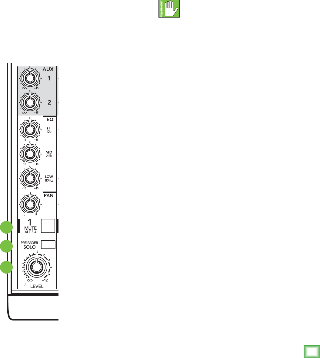
Theeightchannelstripslookalike,andfunction
identically.Theonlydifferenceisthatthefouronthe
leftareforindividualmicsormonoinstrumentsand
havemoregainavailable,whilethenextfourarefor
eitherstereoormonoline-levelsources.(Eachofthe
stereochannelstripsisactuallytwocompletecircuits.
Thecontrolsarelinkedtogethertopreservestereo.)
We’llstartatthebottomandworkourwayup…
“U” Like Unity Gain
VLZ4mixershavea“U”symbolonalmosteverylevel
control.This“U”standsfor“unitygain,”meaningno
changeinsignallevel.Onceyouhaveadjustedtheinput
signaltoline-level,youcanseteverycontrolat“U”and
yoursignalswilltravelthroughthemixeratoptimal
levels.What’smore,allthelabelsonourlevelcontrols
aremeasuredindecibels(dB),soyou’llknowwhat
you’redoinglevel-wiseifyouchoosetochangea
control’ssettings.
Youwon’thavetocheckit
hereandcheckitthere,asyou
wouldwithsomeothermixers.
Infact,somedon’tevenhaveany
referencetoactualdBlevels
atall!Youweresmart—you're
usinga1202VLZ4.
23. Level
Thisadjuststhechannel’s
level…fromoff,tounitygain
atthedetent,onupto12dB
ofadditionalgain.
Thelevelknobisthe
equivalentofachannelfader,
sosometimeswelapseandsay
thewordfader.
Channels1through4usemono
controls,andchannels5through
12usestereocontrols,andso
theymayfeelslightlydifferent.
Notaproblem.
24. Pre-Fader Solo
Thislovableswitchallows
youtohearsignalsthrough
yourheadphonesorcontrol
roomwithouthavingtoroute
themtothemainmixoralt3-4
mix.Youdon’tevenhavetohave
thechannel’slevel[23]knob
turnedup.Folksusesoloinliveworktopreview
channelsbeforetheyareletintothemix,ortojust
23
24
25

14
1202VLZ4
1202VLZ4
[15]andphones[12]outputs.Ifyouwantthealt3–4
signalstogobackintothemainmix,engagetheassign
tomainmix[36]switch,andthecontrolroom/submix
[34]levelcontrolbecomestheoneknobtocontrolthe
levelsofallthechannelsassignedtoalt3–4.
Anotherwaytodothesamethingisassignthe
channelstothealt3–4mix,thenpatchoutofthe
alt3–4output[16]backintoanunusedstereochannel
lineinput[2].Ifthat’syourchoice,don’teverengage
themute/alt3–4switchonthatstereochannel,oryou’ll
haveeverydogintheneighborhoodhowlingatyour
feedbackloop.
Anotherbenetofthealt3–4featureisthatitcan
actasa“SIP”(Solo-In-Place):justengageachannel's
mute/alt3–4switchandthealt3–4switchinthesource
matrixandyou’llgetthatchannel,allbyitself,inthe
controlroomandphones.
Mute/alt3–4isoneofthosecontrolsthatcan
bewildernewcomers,sotakeyourtimeandplay
aroundwithit.Onceyou’vegotitdown,you’ll
probablythinkofahundredusesforit!
26. Pan
Panadjuststheamountof
channelsignalsenttotheleft
versustherightoutputs.On
monochannels(ch.1–4or5–12
withconnectionstotheLinput
only)thesecontrolsactaspan
pots.Onstereochannels(5–12)
withstereoconnectionstoLand
Rinputs,thepanknobworkslike
thebalancecontrolonyourhome
stereo.
Pandeterminesthefateof
themainmixandalt3–4mix.
Withthepanknobhardleft,
thesignalwillfeedeithermain
outL(bus1)oraltoutputL
(bus3),dependingonthe
positionofthealt3–4switch.
Withtheknobhardright,the
signalfeedsmainoutR(bus2)
oraltoutputR(bus4).
26
27
29
28
30
31
Constant Loudness ! ! !
The1202VLZ4’spancontrolsemployadesigncalled
“ConstantLoudness.”Ithasnothingtodowithliving
nexttoanall-nightdisco.Asyouturnthepan[26]knob
fromlefttoright(therebycausingthesoundtomove
fromthelefttothecentertotheright),thesoundwill
appeartoremainatthesamevolume(orloudness).
Ifyouhaveachannelpannedhardleft(orright)and
reading0dB,itmustdipdownabout4dBontheleft
(orright)whenpannedcenter.Todootherwise(the
wayBrandXcompactmixersdo)wouldmakethesound
appearmuchlouderwhenpannedcenter.
3-Band EQ
The1202VLZ4has3-bandequalizationatcarefully
selectedpoints—lowshelvingat80Hz,midpeaking
at2.5kHz,andhishelvingat12kHz.“Shelving”means
thatthecircuitryboostsorcutsallfrequenciespastthe
speciedfrequency.Forexample,rotatingthelowEQ
knob15dBtotherightboostsbassstartingat80Hzand
continuingdowntothelowestnoteyouneverheard.
“Peaking”meansthatcertainfrequenciesforma“hill”
aroundthecenterfrequency—2.5kHzinthecaseof
themidEQ.
27. Low EQ
Thiscontrolgivesyou
upto15dBboostorcut
below80Hz.Thecircuitis
at(noboostorcut)atthe
centerdetentposition.This
frequencyrepresentsthe
punchinbassdrums,bass
guitar,fatsynthpatches,
andsomereallyserious
malesingers.
Usedinconjunctionwith
thelowcut[3]switch,
youcanboostthelowEQ
withoutinjectingatonof
subsonicdebrisintothe
mix.
28. Mid EQ
Shortfor“midrange,”
thisknobprovides15dB
ofboostorcut,centered
at2.5kHz,alsoatatthe
centerdetent.Midrange
EQisoftenthoughtofas
themostdynamic,because
thefrequenciesthatdene
anyparticularsoundarealmostalwaysfoundinthis
range.YoucancreatemanyinterestingandusefulEQ
changesbyturningthisknobdownaswellasup.
20Hz 100Hz 1kHz 10kHz 20kHz
–15
–10
–5
0
+5
+10
+15
20Hz 100Hz 1kHz 10kHz 20kHz
–15
–10
–5
0
+5
+10
+15
Low EQ with Low Cut
Low EQ
20Hz 100Hz 1kHz 10kHz 20kHz
–15
–10
–5
0
+5
+10
+15
Mid EQ
15
Owner’s Manual
Owner’s Manual
29. Hi EQ
Thiscontrolgivesyouup
to15dBboostorcutabove
12kHz,anditisalsoat
at the detent. Use it to
addsizzletocymbals,
andanoverallsenseof
transparency,oredgeto
keyboards,vocals,guitar
andbaconfrying.Turnit
downalittletoreducesibilance,ortohidetapehiss.
Moderation During EQ
WithEQ,youcanalsoscrewthingsuproyally.
We’vedesignedalotofboostandcutintoeach
equalizercircuit,becauseweknoweveryonewill
occasionallyneedthat.ButifyoumaxtheEQson
everychannel,you’llgetmixmush.Equalizesubtly
andusetheleftsidesoftheknobs(cut),aswellas
theright(boost).Veryfewgold-record-albumengineers
everusemorethanabout3dBofEQ.Ifyouneedmore
thanthat,there’susuallyabetterwaytogetit,suchas
placingamicdifferently(orusingadifferentkindof
micentirely).
30. Aux 2 Send
31. Aux 1 Send
Theseknobsallowyoutotapaportionofeach
channelsignalouttoanothersourceforparallel
effectsprocessingorstagemonitoring.Auxsend
levelsarecontrolledbytheseknobsandbythe
aux1master[39].
Thesearemorethanjusteffectsandmonitorsends.
Theycanbeusedtogenerateseparatemixesfor
recordingor“mix-minuses”forbroadcast.Byusing
aux1inthepremode,thesemixlevelscanbeobtained
independentlyofthechannel’slevelcontrol.
Aux1inpostmodeandaux2arepost-lowcut,
post-EQandpost-level.Thatis,thesendsobeythe
settingsofthesecontrols.Aux1inpremodefollows
theEQandlowcutsettingsonly.Panandlevelhave
noeffectonthepresend(seediagrambelow).
20
Hz
100
Hz
1k
Hz
10k
Hz
20k
Hz
–15
–10
–5
0
+5
+10
+15
High EQ
GAIN INSERTLO CUT EQ
LEVEL PAN MAIN / ALT
AUX 2 KNOB
"POST" SIGNAL
"PRE" SIGNAL
AUX 1 KNOB
"POST" SIGNAL OBEYS
MUTE STATUS
INPUT
AUX SEND 1 PRE/POST SWITCH
(IN MASTER SECTION)
TO AUX SEND 2 LEVEL
TO AUX SEND 1 LEVEL
Eachauxsendlevelrangesfromoffthroughunity
(thecenterdetentposition)onupto15dBofextragain
(whenturnedfullyclockwise).Chancesareyou’llnever
needthisextragain,butit’snicetoknowit’sthereif
youdo.
Channel5–12auxknobscontrolthemonosumofthe
channel’sstereosignalsforeachauxsend.Forinstance,
channel5(L)and6(R)mixtogethertofeedthat
channel’sauxsendknobs.
Werecommendgoingintoastereoreverbinmonoand
returninginstereo.Wehavefoundthatonmost“stereo”
reverbsthesecondinputjusttiesupanextraauxsend
andaddsnothingtothesound.Thereareexceptions,
sofeelfreetotryitbothways.Ifyoureffectsdeviceis
truestereoallthewaythrough,useaux1tofeeditsleft
inputandaux2tofeedtherightinput.
Stillwithus?Goodforyou.Herecomethetricky
parts,theoutputormastersectionwherethemixingis
reallydone.Wehaveevenstarteditonanewpage:
“Pre vs. Post”
Signal Flow Diagram
16
1202VLZ4
1202VLZ4
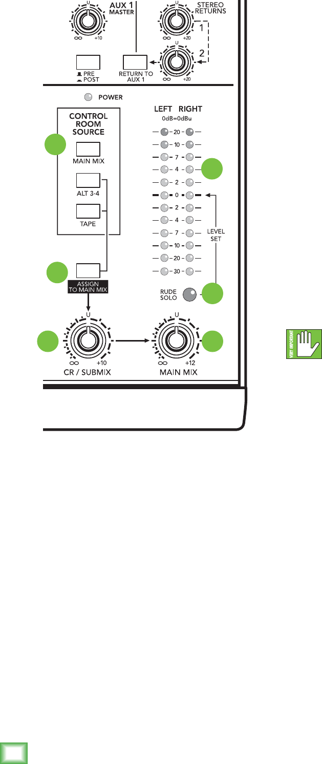
Output Section
32
33
34
35
36
37
33. Control Room Source Matrix
Typically,theengineersendsthemainmixtoan
audience(iflive)oramixdowndeck(ifrecording).But
whatiftheengineerinthecontrolroomneedstohear
somethingotherthanthemainmix?Withthe1202VLZ4,
theengineerhasseveralchoicesofwhattolistento.
Thisisoneofthosetrickyparts,sobraceyourself.
Viathesesourceswitches,youcanchoosetolisten
toanycombinationofmainmix,alt3-4andtape.
Bynow,youprobablyknowwhatthemainmixis.
Alt3-4isthatadditionalstereomixbus.Tapeisthe
stereosignalcominginfromthetapeinput[9]jacks.
Selectionsmadeinthesourcematrixdeliverstereo
signalstothecontrolroom,phonesandmeterdisplay.
Withnoswitchesengaged,therewillbenosignalat
theseoutputsandnometerindication.
Theexceptionisthesolofunction.Regardlessofthe
sourceselection,engagingachannel’ssolo[24]switch
willreplacethatselectionwiththesolosignal,alsosent
tothecontrolroom,phonesandrightmeter(theleft
meterbecomesinactive).Thisiswhatmakesthe
level-settingproceduresoeasytodo.
WARNING:Engagingboththetapeand
assigntomainmix[36]buttonscancreate
afeedbackpathbetweentapeinput[9]and
tapeoutput[10].Makesureyourtapedeckisnotin
record,record-pause,orinput-monitormodewhenyou
engagetheseswitches,ormakesurethecontrolroom/
submix[34]levelknobisfullycounterclockwise(off).
Nowyouknowhowtoselectthesignalstosendtothe
engineer’scontrolroomorphones.Fromthere,these
signalsallpassthroughthesamelevelcontrol:
34. Control Room/Submix
Thisknobcontrolsthelevelsofboththestereo
controlroom[15]andphones[12]outputs.Thecontrol
rangeisfromoffthroughunitygainatthedetent,with
10dBofextragain(whenturnedfullyclockwise).
Whenmainmixisyourcontrolroomsourceselection,
thosesignalswillnowpassthroughtwolevelcontrols
onthewaytoyourcontrolroomampandphones—the
mainmix[32]knobandthiscontrolroom/submix
knob.Thisway,youcansendanicehealthyleveltothe
mainoutput(mainmixknobat“U”),andaquietlevel
tothecontrolroomorphones(controlroom/submix
knobwhereveryoulikeit).
Whenalt3-4ortapeisselected,orsolo[24]is
engaged,thecontrolroom/submixknobwillbethe
onlyonecontrollingtheselevels(channelcontrols
notwithstanding).
32. Main Mix
Thisknobcontrolsthelevelsofsignalssenttothe
mainoutputs:XLR[13]and1⁄4"[11]andRCAtape
output[10].Allchannelsandstereoreturns[7]that
arenotmutedorturnedfullydownwillwindupinthe
mainmix.
Fullycounterclockwiseisoff,thecenterdetent
isunitygain,andfullyclockwiseprovides12dBof
additionalgain.Thisadditionalgainwilltypicallynever
beneeded,butonceagain,it’snicetoknowit’sthere.
Thisistheknobtoturndownattheendofthesong
whenyouwantTheGreatFade-Out.

17
Owner’s Manual
Owner’s Manual
Whateveryourselection,youcanalsousethecontrol
room[15]outputsforotherapplications.Itssound
qualityisjustasimpeccableasthemainouts[11and
13].Itcanbeusedasadditionalmainmixoutput,which
maysoundsillysincetherearealreadythree,butthis
onehasitsownlevelcontrol.However,shouldyoudo
somethinglikethis,besurethatyoudonotengagea
soloswitch,asthatwillinterruptyoursourceselection.
A Word About Pre-Fader Solo (PFL)
Engagingachannel’ssolo[24]switchwillcause
thisdramaticturnofevents:Anyexistingcontrolroom
sourceselectionswillbereplacedbythesolosignal,
appearinginthecontrolroom,headphones,andinthe
rightmeter.Theaudiblesololevelsarethencontrolled
bythecontrolroom/submix[34]knob.Thesololevels
appearingontherightmeterdisplayarenotcontrolled
byanything—youwouldn’twantthat.Youwanttosee
theactualchannellevelonthemeterdisplayregardless
ofhowloudyou’relistening.
“Pre-fader”solomeansthatthechannelsignalis
beingtappedbeforethechannel’slevel[23]knob
(notreallyafaderinthiscase,butwewereafraid
you’dlaughifwecalleditpre-knobsolo).Itdoes,
however,obeygain[4],lowcut[3]andEQ[27]
settings,makingittheperfecttoolforquickinspections
ofsuspectchannels.Thechannel’span[26]andmute/
alt3-4[25]settingshavenoeffectonthesolosignal.
Note:Forstereochannels5-12,thesolosignalis
themonosumoftheleft(odd-numbered)andright
(even-numbered)signalsforthatchannelstrip.
WARNING:Pre-fadersolo[24]taps
thechannelsignalbeforethelevelknob.
Ifyouhaveachannel’slevelknobsetbelow
“U”(unitygain),solowon’tknowthat,andwillsend
aunitygainsignaltothecontrolroom,phonesand
meterdisplay,thatmayresultinastartlinglevelboost
attheseoutputs.
35. Rude Solo Light
ThisashingLightEmittingDiodeservestwo
purposes—toremindyouthatatleastonechannel
isinsolo,andtoletyouknowthatyou’remixingon
a1202VLZ4.Noothercompanyissoconcernedabout
yourlevelofsoloawareness.Ifyouworkonamixer
thathasasolofunctionwithnoindicatorlights,and
youhappentoforgetyou’reinsolo,youcaneasilybe
trickedintothinkingthatsomethingiswrongwithyour
mixer.Hencetherudesololight.It’sespeciallyhandy
atabout3a.m.whennosoundiscomingoutofyour
monitorsbutyourmultitrackisplayingbacklikemad.
36. Assign To Main Mix
Let’ssayyou’redoingaliveshow.Intermissionis
nearingandyou’llwanttoplayasoothingCDforthe
crowdtopreventthemfromeatingthefurniture.
Thenyouthink,“ButIhavetheCDplayerpluggedinto
thetapeinputs,andthatnevergetstothemainouts!”
Oh,butitdoes.Simplyengagethisswitchandyour
controlroomsourceselection,aftergoingthrough
thecontrolroom/submix[34]knob,willfeedinto
themainmix,justasifitwereanotherstereochannel.
Anotherhandyuseforthisswitchistoenablethe
alt3-4mixtobecomeasubmixofthemainmix,using
thecontrolroom/submixknobasitslevelcontrol.
Sideeffects:(1)Engagingthisswitchwillalsofeed
anysoloedchannelsintothemainmix,whichmaybe
thelastthingyouwant.(2)Ifyouhavemainmixas
yourcontrolroomsourceselectionandthenengage
assigntomainmix,themainmixlinestothecontrol
roomwillbeinterruptedtopreventfeedback.Then
again,whywouldanyonewanttoassignthemainmix
tothemainmix?
37. Meters – Many Displays In One!
The1202VLZ4’speakmeteringsystemismadeup
oftwocolumnsoftwelveLEDs.Deceptivelysimple,
consideringthemultitudeofsignalsthatcanbe
monitoredbyit.
Ifnothingisselectedinthesourcematrixand
nochannelsareinsolo,themeterswilljustsitthere
anddonothing.Toputthemtowork,youmustmakea
selectioninthesourcematrix(orengageasoloswitch).
Why?Youwantthemeterdisplaytoreectwhatthe
engineerislisteningto,andaswe’vecovered,the
engineerislisteningeithertothecontrolroom[15]
outputsorthephones[12]outputs.Theonlydifference
isthatwhilethelisteninglevelsarecontrolledbythe
controlroom/submix[34]knob,themetersreadthe
sourcemixbeforethatcontrol,givingyoutherealfacts
atalltimes,evenifyou’renotlisteningatall.
Thankstothe1202VLZ4’swidedynamicrange,
youcangetagoodmixwithpeaksashinganywhere
between–20and+10dBonthemeters.Most
ampliersclipatabout+10dB,andsomerecorders
aren’tsoforgivingeither.Forbestreal-worldresults,
trytokeepyourpeaksbetween“0”and“+7”.
Youmayalreadybeanexpertattheworldof“+4”(+4
dBu=1.23V)and“–10”(–10dBV=0.32V)operating
levels.Basically,whatmakesamixeroneortheother
istherelative0dBVU(or0VU)chosenforthemeters.
A“+4”mixer,witha+4dBusignalpouringouttheback
willactuallyread0VUonitsmeters.A“–10”mixer,
witha–10dBVsignaltricklingout,willread0VUonits
meters.Sowhenis0VUactually0dBu?Rightnow!
18
1202VLZ4
1202VLZ4
Attheriskofcreatinganotherstandard,1202VLZ4
mixersaddresstheneedofbothcrowdsbycallingthings
astheyare—0dBu(0.775V)attheoutputshowsas
0dBVUonthemeters.Whatcouldbeeasier?Bythe
way,themostwonderfulthingaboutstandardsisthat
therearesomanytochoosefrom.
Remember,audiometersarejusttoolstohelpassure
youthatyourlevelsare“intheballpark.”Youdon’thave
tostareatthem(unlessyouwantto).
A Word About Aux
Firstofall,thereisnoparticularalliancebetween
auxsend1(or2)andstereoreturn1(or2).They’re
justnumbers.They’reliketwocompletestrangers.
Sendsareoutputs,returnsareinputs.Thechannel
aux[30and31]knobstapthesignaloffthechannel
andsendsittotheauxsend[8]outputs.Aux1signalis
senttotheaux1master[39]knobbeforegoingtothe
auxsend1[8]outputandtheaux2signalgoesdirectly
totheauxsend2[8]output.
38
39
41 40
Theseoutputscanbefedtotheinputsofareverbor
otherdevice.Fromthere,theoutputsofthisexternal
devicearefedbacktothemixer’sstereoreturn[7]
jacks.thenthesesignalsaresentthroughthestereo
return[40]levelcontrols,andnallydeliveredtothe
mainmix.
So,theoriginal“dry”signalsgofromthechannels
tothemainmixandtheaffected“wet”signalsgofrom
thestereoreturn[7]tothemainmix,andoncemixed
together,thedryandwetsignalscombinetocreate
aglorioussound.So,armedwiththisknowledge,
let’svisittheAuxiliaryWorld:
38. Pre Or Post (Aux 1)
Besidesbeingusedtoworkeffectsintoyourmix,aux
sendsserveanothercriticalrole—thatofdelivering
cuemixestostagemonitors,somusicianscanhearwhat
they’redoing.Onthe1202VLZ4,auxsend1canplay
eitherrole,dependingonthepositionofthisswitch.
Withthisswitchup(disengaged),auxsend1will
tapachannelpre-fader(level)andpre-mute/alt3-4,
meaningthatnomatterhowyoumanipulatethose
controlsastheyfeedthemainmix,theauxsendwill
continuetobeltoutthatchannel’ssignal.Thisisthe
preferredmethodforsettingupstagemonitorfeeds.
EQsettingswillaffectallauxsends.
Withtheswitchdown,theauxsend1becomes
anordinaryeffectssend—post-fader(level)and
post-mute/alt3-4.Thisisamustforeffectssends,
sinceyouwantthelevelsofyour“wet”signalsto
followthelevelofthe“dry.”
39. Aux 1 Master
Thisknobprovidesoveralllevelcontrolofauxsend1,
justbeforeit’sdeliveredtotheauxsend1[8]output.
(Auxsend2hasnosuchcontrol.)Thisknobgoesfrom
off(turnedfullydown),tounitygainatthecenter
detent,with10dBofextragain(turnedfullyup).
Aswithsomeotherlevelcontrols,youmayneverneed
theadditionalgain,butifyoueverdo,you’llbegladyou
boughta1202VLZ4.
Thisisusuallytheknobyouturnupwhenthelead
singerglaresatyou,pointsathisstagemonitor,and
stickshisthumbupintheair.(Itwouldfollowsuitthat
ifthesingerstuckhisthumbdown,you’dturntheknob
down…butthatneverhappens.)
40. Stereo Returns
Thesetwocontrolssettheoveralllevelofeffects
receivedfromstereoreturn[7]inputs1and2.These
controlsaredesignedtohandleawiderangeofsignal
levels,fromoff,tounitygainatthedetent,with20dB
gainfullyclockwise,tocompensateforlow-leveleffects.

19
Owner’s Manual
Owner’s Manual
Typically,theseknobscanjustliveatthecenter
detent,andtheeffectsdevice’soutputcontrolshould
besetatwhatevertheycallunitygain(checktheir
manual).Ifthatturnsouttobetooloudortooquiet,
adjusttheeffectsdevice’soutputs,notthemixer.
Thatway,themixer’sknobsareeasytorelocate
at the center detent.
Signalspassingthroughthesecontrolswillproceed
directlytomainmix,withoneexception(seeparagraph
below).Thestereoreturnsdonothavemute/alt3-4
switches,soifyouwantthesesignalstogettothealt3-4
mix,you’llhavetopatchtheeffectsdevice’soutputsinto
oneofthestereochannels,andmute/altthosechannels.
41. Return To Aux 1
Ifyouwanttoaddreverbordelaytothestagemonitor
mixesofaux1,thisistheswitchforyou.
Withtheswitchup,stereoreturn1and2behave
normally—theydelivertheirsignalsintothemain
mix.Withtheswitchdown,stereoreturn1stillbehaves
normally,butstereoreturn2willfeedauxsend1
insteadofthemainmix.
Stillwithus?Good.Sofar,withtheswitchdown,we
havestereoreturn1feedingthemainmixandstereo
return2feedingauxsend1.Now,supposeyouonlyhave
oneeffectsdevice,andyouwantittofeedboththemain
mixandauxsend1.That’swhere“jacknormalling”
comesin:
Jack Normalling
Jacknormalling(nottobeconfusedwithJack
Normalling,ChicagoCubsutilityinelder,1952-61,
.267LBA)isafeaturefoundonalmosteverymixer,
keyboardandeffectsdevice.Thesejackshavespecial
spring-loadedpinsthatconnecttothesignalpins,
butwhensomethingispluggedintothejack,that
connectionisbroken.
Thesenormallingpinscanbeusedinallsortsof
ways.Theubiquitousphrase“left(mono)”meansthat
ifyouplugasignalintotheleftsideandhavenothing
intherightside,thatsignalisalsofedtotheright
input,courtesyofjacknormalling.Assoonasyouplug
somethingintherightside,thatnormalledconnection
isbroken.
Howdoesallthisrelatetothe
returntoaux1[41]switch?Stereo
return1’sinputsarenormalledto
stereoreturn2.Ifyouhaveone
effectsdevice,plugitintostereo
return1.Plugnothingintostereo
return2.Nowthesignalsfeeding
thestereoreturn1inputswillalsobesenttothestereo
return2inputs.
Engagethereturntoaux1switch,andnowthestereo
return2knobwillbecomeanadditionalauxsend1
knobforthesignalatauxreturn1.Saythattentimes
fast!Onceagain,auxreturn1willbehavenormally,as
always.
Congratulations!You’vejustreadaboutallthe
featuresofyour1202VLZ4.You’reprobablyreadyfor
acoldone.Goahead.Therestofthemanualcanwait.

20
1202VLZ4
1202VLZ4
Appendix A: Service Information
Ifyouthinkyour1202VLZ4hasaproblem,please
checkoutthefollowingtroubleshootingtipsanddo
yourbesttoconrmtheproblem.VisittheSupport
sectionofourwebsite(www.720trees.com)where
youwillndlotsofusefulinformationsuchasFAQs
andotherdocumentation.Youmayndtheanswer
totheproblemwithouthavingtosendyourmixeraway.
Troubleshooting
Bad Channel
• Isthemute/alt3–4switchinthecorrect
position?
• Isthelevelknobturnedup?
• Tryunplugginganyinsertdevices(channels
1–4only).
• Trythesamesourcesignalinanotherchannel,
setupexactlylikethesuspectchannel.
Bad Output
• Istheassociatedlevelknob(ifany)turnedup?
• Ifit’soneofthemainouts,tryunpluggingall
theothers.Forexample,ifit’sthe1⁄4"leftmain
out,unplugtheRCAandXLRLeftoutputs.If
theproblemgoesaway,itsnotthemixer.
• Ifit’sastereopair,tryswitchingthemaround.
Forexample,ifaleftoutputispresumeddead,
switchtheleftandrightcords,atthemixer
end.Iftheproblemswitchessides,it’snotthe
mixer.
Noise
• Turnthechannellevelandauxreturnknobs
down,onebyone.Ifthesounddisappears,it’s
eitherthatchannelorwhateverisplugged
intoit,sounplugwhateverthatis.Ifthenoise
disappears,it’sfromyourwhatever.
Power
• Unplugthepowercordandcheckthefuse.
Repair
Forwarrantyservice,refertothewarranty
informationonpage27.
Non-warrantyserviceisavailableatafactory-
authorizedservicecenter.Tolocatethenearest
servicecenter,visitwww.720trees.com,click“Contact
TechSupport”andselect“LocateaServiceCenter
orDistributor”[3].Servicefora1202VLZ4living
outsidetheUnitedStatesmaybeobtainedthrough
localdealersordistributors.
Ifyoudonothaveaccesstoourwebsite,youcan
callourTechSupportdepartmentat1-800-898-3211,
Monday-Friday,duringnormalbusinesshours,Pacic
Time,toexplaintheproblem.TechSupportwilltell
youwherethenearestfactory-authorizedservice
centerislocatedinyourarea.
Appendix B: Connections
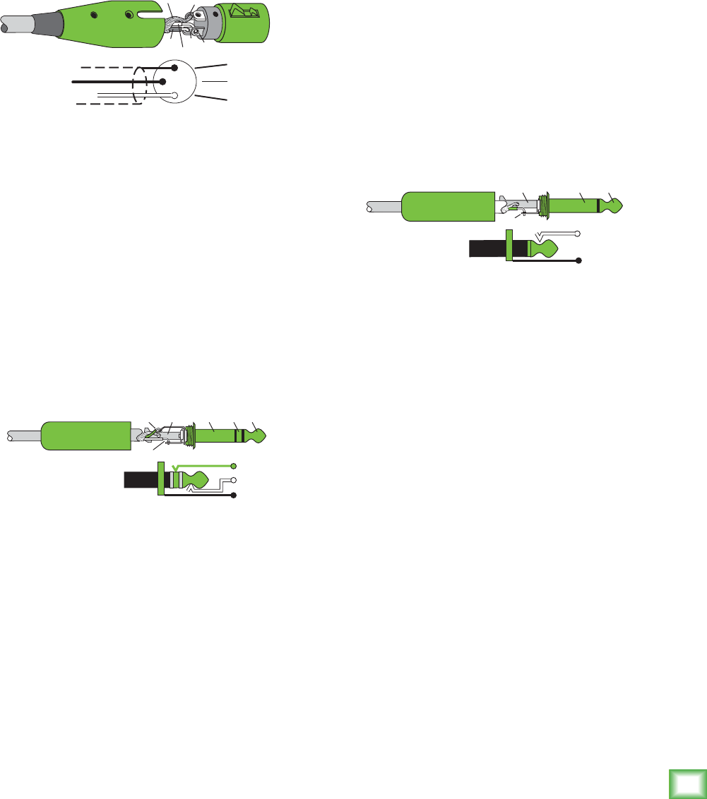
Balanced XLR Input Connector
The1202VLZ4mixerhasfourfemaleXLR
inputs.BesurethecablesarewiredperAES
(AudioEngineeringSociety)standards:
Balanced XLR Input Connector
Pin1–Shield(Ground)
Pin2–Positive(+orhot)
Pin3–Negative(–orcold)
2
31
SHIELD
COLD
HOT
SHIELD
COLD
HOT
3
2
1
Balanced XLR Input Connector
21
Owner’s Manual
Owner’s Manual
Balanced XLR Output Connector
ThemaleXLRconnectorsprovideabalancedline-
levelsignalthatrepresentstheendofthemixer,where
thefullymixedstereosignalenterstherealworld.
Connectthesetotheleftandrightline-levelinputs
ofpoweredspeakersortotheleftandrightline-level
inputsofanamplier(withspeakersalreadyattached).
BesurethecablesarewiredperAES(Audio
EngineeringSociety)standards:
Balanced XLR Output Connector
Pin1–Shield(Ground)
Pin2–Positive(+orhot)
Pin3–Negative(–orcold)
Balanced 1/4" TRS Connector
TRSstandsforTip-Ring-Sleeve,thethreeconnections
availableonastereo1/4"cable.Thisallowsforadirect
connectiontothechannelinputjacks.Besurethe
cablesarewiredperAES(AudioEngineeringSociety)
standards:
Balanced 1/4" TRS Connector
Sleeve–Shield(Ground)
Tip–Positive(+orhot)
Ring–Negative(–orcold)
TRSjacksandplugsareusedinseveraldifferent
applications:
• Balancedmonocircuits.Whenwiredasa
balancedconnector,a1⁄4"TRSjackorplug
isconnectedtiptosignalhigh(hot),ringto
signallow(cold),andsleevetoground(earth).
• StereoHeadphones,andrarely,stereo
microphonesandstereolineconnections.
Whenwiredforstereo,a1⁄4"TRSjackorplug
isconnectedtiptoleft,ringtorightandsleeve
toground(earth).VLZ4mixersdonotdirectly
2
1
SHIELD
COLD
HOT
3
SHIELD
COLD
HOT
3
2
1
Balanced XLR Output Connector
SLEEVE
TIP
SLEEVE
TIP
RING
RING
TIP
SLEEVERING
Balanced 1/4" TRS Connector
accept1-plug-typestereomicrophones.They
mustbeseparatedintoaleftcordandaright
cord,whicharepluggedintothetwomic
preamps.
Youcancookupyourownadapterforastereo
microphone.“Y”twocablesoutofafemale1⁄4"
TRSjacktotwomaleXLRplugs,oneforthe
rightsignalandonefortheleft.
• Unbalancedsend/returncircuits.Whenwired
asasend/return“Y”connector,a1⁄4"TRSjack
orplugisconnectedtiptosignalsend(output
frommixer),ringtosignalreturn(inputback
intomixer),andsleevetoground(earth).
Unbalanced 1/4" TS Connector
TSstandsforTip-Sleeve,thetwoconnections
availableonamono1⁄4"cable.Thisallowsforadirect
conectiontothechannelinputjacks.Besurethecables
arewiredperAES(AudioEngineeringSociety)
standards:
Unbalanced 1/4" TS Connector
Sleeve–Shield(Ground)
Tip–Positive(+orhot)
TSjacksandplugsareusedinmanydifferent
applications,alwaysunbalanced.Thetipisconnected
totheaudiosignalandthesleevetoground(earth).
Someexamples:
• Unbalancedmicrophones
• Electricguitarsandelectronicinstruments
• Unbalancedline-levelconnections
Switched 1/4" Phone Jacks
Switchescanbeincorporatedinto1⁄4"phonejacks,
whichareactivatedbyinsertingtheplug.These
switchesmayopenaninsertloopinacircuit,change
theinputroutingofthesignalorserveotherfunctions.
The1202VLZ4usesswitchesinthechannelinsertand
businsertjacks,inputjacksandstereoreturns.Italso
usestheseswitchestogroundtheline-levelinputswhen
nothingispluggedintothem.
Inmostcases,theplugmustbeinsertedfullyto
activatetheswitch.The1202VLZ4takesadvantageof
thisinsomecircuits,specifyingcircumstanceswhere
youaretoinserttheplugonlypartially.See“Special
Connections”,onthenextpage.
SLEEVE
TIP
TIP
SLEEVE
TIP
SLEEVE
Unbalanced 1/4" TS Connector

22
1202VLZ4
1202VLZ4
Unbalanced RCA Connector
RCA-typeplugs(alsoknownasphonoplugs)
andjacksareoftenusedinhomestereoandvideo
equipmentandinmanyotherapplications.RCAplugs
areunbalanced.Connectthesignaltothecenterpost
andtheground(earth)orshieldtothesurrounding
“basket.”BesurethecablesarewiredperAES(Audio
EngineeringSociety)standards:
Unbalanced RCA Connector
Sleeve–Shield(Ground)
Tip–Positive(+orhot)
Unbalancing a Line
Inmoststudio,stageandsoundreinforcementsitu-
ations,thereisacombinationofbalancedandunbal-
ancedinputsandoutputsonthevariouspiecesof
equipment.Thisusuallywillnotbeaprobleminmaking
connections.
• Whenconnectingabalancedoutputtoan
unbalancedinput,besurethesignalhigh(hot)
connectionsarewiredtoeachother,andthat
thebalancedsignallow(cold)goestothe
ground(earth)connectionattheunbalanced
input.Inmostcases,thebalancedground
(earth)willalsobeconnectedtotheground
(earth)attheunbalancedinput.Ifthereare
ground-loopproblems,thisconnectionmaybe
leftdisconnectedatthebalancedend.
• Whenconnectinganunbalancedoutputtoa
balancedinput,besurethatthesignalhigh
(hot)connectionsarewiredtoeachother.The
unbalancedground(earth)connectionshould
bewiredtothelow(cold)andtheground
(earth)connectionsofthebalancedinput.If
thereareground-loopproblems,tryconnecting
theunbalancedground(earth)connectiononly
totheinputlow(cold)connection,andleaving
theinputground(earth)connectiondiscon-
nected.
• Insomecases,youwillhavetomakeupspecial
adapterstointerconnectyourequipment.For
example,youmayneedabalancedXLRfemale
connectedtoanunbalanced1⁄4"TSphone
plug.
TIPSLEEVETIPSLEEVE
Unbalanced RCA Connector
TRS Send/Receive Insert Jacks
Single-jackinsertsarethree-conductor,TRS-type1⁄4"
phone.Theyareunbalanced,buthaveboththemixer
output(send)andthemixerinput(return)signalsin
oneconnector.Seetheillsutrationbelow.
Thesleeveisthecommonground(earth)forboth
signals.Thesendfromthemixertotheexternalunitis
carriedonthetip,andthereturnfromtheunittothe
mixerisonthering.
Special Connections
Thebalanced-to-unbalancedconnectionhasbeenan-
ticipatedinthewiringof1202VLZ4jacks.A1⁄4"TSplug
insertedintoa1⁄4"TRSbalancedinput,forexample,
willautomaticallyunbalancetheinputandmakeallthe
rightconnections.Conversely,a1⁄4"TRSpluginserted
intoa1⁄4"unbalancedinputwillautomaticallytiethe
ring(loworcold)toground(earth).
Using the Send Only on an Insert Jack
IfyouinsertaTS(mono)1⁄4"plugonlypartially(to
therstclick)intoaVLZ4insertjack,theplugwillnot
activatethejackswitchandwillnotopentheinsert
loopinthecircuit(therebyallowingthechannelsignal
tocontinueonitsmerrywaythroughthemixer).
Thisallowsyoutotapoutthechannelorbussignal
withoutinterruptingnormaloperation.
Ifyoupushthe1⁄4"TSplugintothesecondclick,
youwillopenthejackswitchandcreateadirectout,
whichdoesinterruptthesignalinthatchannel.Seethe
illustrationonthenextpage.
Unbalanced 1/4" Insert Connectors
tip
This plug connects to one of the
mixer’s Channel Insert jacks. ring
tip ring
sleeve
SEND to processor
RETURN from processor
(TRS plug)

23
Owner’s Manual
Owner’s Manual
NOTE:Donotoverloadorshort-circuitthesignalyou
aretappingfromthemixer.Thatwillaffecttheinternal
signal.
Direct out with no signal interruption to master.
Insert only to first click.
Channel Insert jack
Channel Insert jack
Channel Insert jack
Direct out with signal interruption to master.
Insert all the way in to the second click.
For use as an effects loop.
(Tip = Send TO effect, Ring = Return FROM effect).
MONO PLUG
MONO PLUG
STEREO
PLUG
Using the Send Only on an Insert Jack
Y-cord splitter cable
VLZ4 Stereo Inputs and Returns:
Mono, Stereo, Whatever
Stereolineinputsandstereoreturnsareane
exampleofourphilosophy(whichwejustmadeup)
ofMaximumFlexibilitywithMinimumHeadache.
Theinputsandreturnswillautomaticallybemono
orstereo,dependinguponhowyouusethejacks.
Here’showitworks:
Amonosignalshouldbepatchedintotheinput
orreturnjacklabeledleft(mono).Thesignalwill
beroutedtoboththeleftandrightsidesofthereturn
circuit,andwillshowupinthecenterofthestereopair
ofbusesit’sassignedto,oritcanbepannedwiththe
pan[26]control.
Astereosignal,havingtwoplugs,shouldbepatched
intotheleft(mono)andtherightinputorreturnjacks.
Ajackswitchintherightjackwilldisablethemono
function,andthesignalswillshowupinstereo.
Amonosignalconnectedtotherightjackwillshow
upintherightbusonly.Youprobablywillonlywantto
usethissophisticatedeffectforspecialoccasions.
Mults and “Y”s
Amultor“Y”connectorallowsyoutorouteoneoutput
totwoormoreinputsbysimplyprovidingparallel
wiringconnections.Youcanmake“Y”sandmultsfor
theoutputsofbothunbalancedandbalancedcircuits.
Remember:Onlymultor“Y”oneoutputinto
severalinputs.Ifyouneedtocombineseveral
outputsintooneinput,youmustuseamixer,
notamultora“Y.”
TIP
(SEND)
RING (IN)
TIP (OUT)
RING
(RETURN)
TO MIXER
CHANNEL INSERT
RING (RETURN)
TIP (SEND)
TO
PROCESSOR
INPUT
FROM
PROCESSOR
OUTPUT
Y-cord insert cable
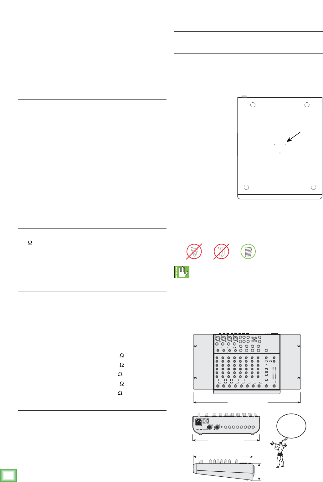
24
1202VLZ4
1202VLZ4
Appendix C: Technical Information
Specifications
Main Mix Noise
(20 Hz–20 kHz bandwidth, 1/4" Main out, channels 1–4 Trim @
unity gain, channel EQs flat, all channels assigned to Main Mix,
channels 1 and 3 Pan left, 2 and 4 Pan right.)
Main Mix knob down, channel Gain knobs down: –100 dBu
Main Mix knob unity, channel Gain knobs down: –86.5 dBu
(90 dB Signal to Noise Ratio, ref +4 dBu)
Main Mix knob @ unity, channel Gain knobs @ unity: –84.5 dBu
Total Harmonic Distortion (THD)
(1 kHz @ 30 dB gain, 20 Hz–20 kHz bandwidth)
Mic pre @ insert: 0.0007%
Attenuation (Crosstalk)
(1 kHz relative to 0 dBu, 20 Hz–20 kHz bandwidth,
Line in, 1⁄4" Main Out, Trim @ unity.)
Main Mix knob down: –75 dBu
Channel Alt / Mute switch engaged: –85 dBu
Channel Gain knob down: –87 dBu
Frequency Response
Mic Input to Main Output (Gain @Unity)
+0, –1 dB, 20 Hz to 50 kHz
+0, –3 dB, <10 Hz to >100 kHz
Equivalent Input Noise (EIN)
(Mic in to Insert Send out, max gain.)
150 termination: –128.5 dBu 20 Hz–20 kHz
Common Mode Rejection Ratio (CMRR)
(Mic in to Insert Send out, max gain.)
1 kHz: better than –70 dB
Maximum Levels
Mic in: +22 dBu
Tape in: +16 dBu
All other inputs: +22 dBu
Main Mix XLR out: +28 dBu
All other outputs: +22 dBu
Impedances
Mic in: 2.5 k
Channel Insert return: 2.5 k
All other inputs: 10 k or greater
Tape out: 1.1 k
All other outputs: 120
EQ
High Shelving ±15 dB @ 12 kHz
Mid Peaking ±15 dB @ 2.5 kHz
Low Shelving ±15 dB @ 80 Hz
Power Consumption
25 watts
Fuse Rating
100-120V: 500 mA slo blo, 5 x 20 mm
220-240V: 250 mA slo blo, 5 x 20 mm
Dimensions (H x W x D)
10.7" x 11.9" x 3.0" (272 mm x 303 mm x 75 mm)
Weight
6.5 lb (3.0 kg)
Microphone Stand
Thebottompanelof
the1202VLZ4hasthree
non-threadedholesthat
allowittobettedwith
anoptionalmicrophone
standadapter.This
allowsyoutosupport
themixeronastandard
micstand,andadjust
its height and level to
whateversuitsyour
strangely-complexsetof
preferences.
1. Order the Atlas
AD-11Bmic
standadapter
availablefrom
manyanemusicstore.(Itismadeanddistributed
byAtlasSound.)
2. UsethreeTrilobularthreadrollingscrews
6-32x1/4"longtosecuretheadapterto
thebottomofthe1202VLZ4[seebelow].
Donotusescrewslongerthan1/4",asthesecould
damagethecircuitboards.Donotusescrews
shorterthan1/4",ortheadapterwillnotbesecurely
xedtothemixer.
3. DonotordertheAtlasAD-11,asthisisapack
of100.Ifyoudo,pleasesendfortheinformative
bookletentitled99 things to do with a mic stand
adapter.
bottom panel
Holes for mic
stand adapter
WEIGHT
6.5 lb
3.0 kg
19.0 in / 483 mm
(optional Rack Mount Kit)
3.0 in
75 mm
11.9 in / 303 mm
10.7 in / 272 mm
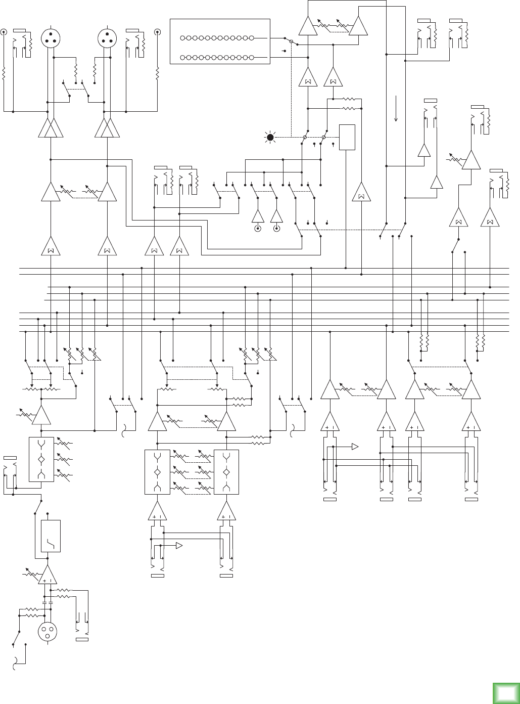
25
Owner’s Manual
Owner’s Manual
Block Diagram
75Hz
HPF
MID HI
80 2K5 12K
LO
MID HI
80 2K5 12K
LO
MID HI
80 2K5 12K
LO
SOLO
RELAY
20
10
7
4
2
0
2
4
7
10
20
30
MAIN L
MAIN R
ALT L
ALT R
AUX SEND 1 PRE
AUX SEND 1 POST
AUX SEND 2 POST
SOLO
LOGIC
PHANTOM POWER
MIC IN
LINE IN
GAIN
INSERT
LO CUT
3-BAND EQ
LEVEL PA N MAIN / ALT
AUX
SENDS
SOLO (PFL)
MONO CHANNEL
(1 OF 4)
2
1
3
STEREO CHANNEL
(1 OF 4)
LINE IN L
LINE IN R
3-BAND EQ
LEVEL PA N
MAIN / ALT
STEREO RETURN 1
L IN
R IN
STEREO RETURN 2
L IN
(MONO)
R IN
GAIN
GAIN
RETURN TO
AUX 1
MAIN MIX MAIN
LEVEL 30dB PAD
TAPE OUT L
LINE OUT L
BAL OUT L
BAL OUT R
LINE OUT R
ALT MIX
ALT OUT L
ALT OUT R
ALT
TAPE
MAIN
SOURCE
CONTROL ROOM &
PHONES LEVEL
METERING
(0dBu = 0VU)
LEFT
RIGHT
CONTROL ROOM OUT
PHONES OUT
AUX MIX
AUX 1
PRE / POST
AUX SEND 2
AUX SEND 1
SOLO MIX
ASSIGN TO MAIN
TAPE IN +6dB
L
RCONTROL ROOM &
PHONES MIX
2
31
2
31
RUDE SOLO LED
SOLO (PFL)
AUX 2
AUX 1
AUX 1 LEVEL
TAPE OUT R
Since we are always striving to make our products better by
incorporating new and improved materials, components, and
manufacturing methods, we reserve the right to change these
specifications at any time without notice.
The “Running Man” figure is a registered trademark of
LOUD Technologies Inc. All other brand names mentioned
are trademarks or registered trademarks of their respective
holders, and are hereby acknowledged.
©2014 LOUD Technologies Inc. All Rights Reserved.
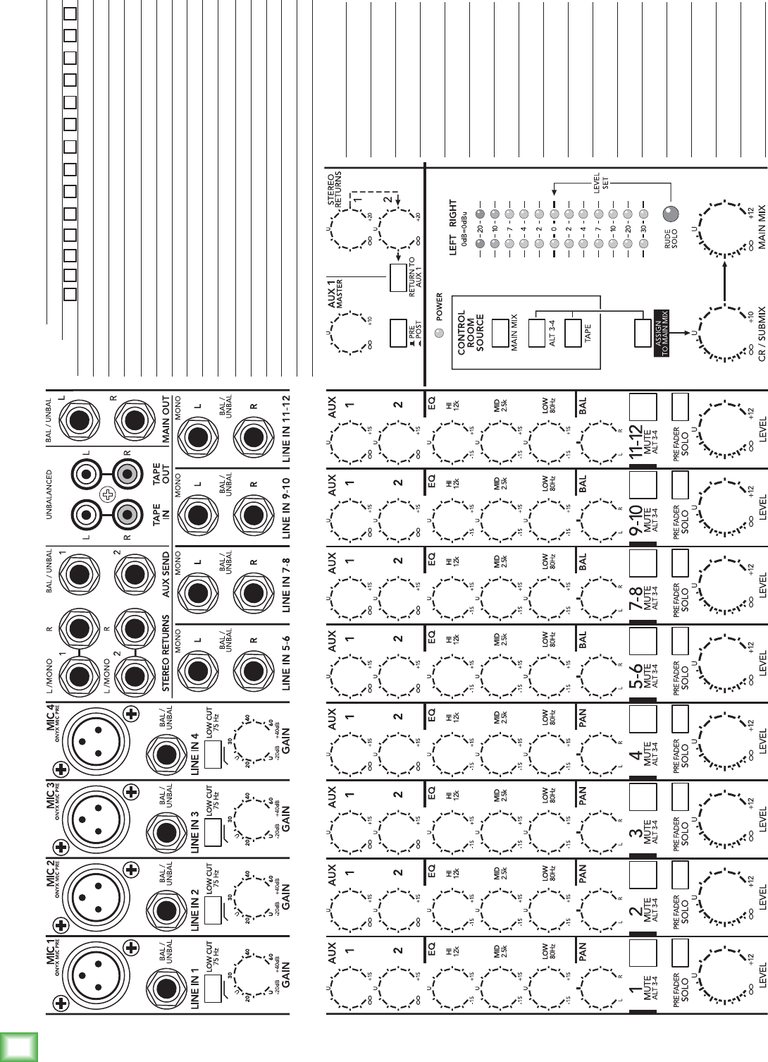
26
1202VLZ4
1202VLZ4
Track Sheet
SESSION:
DATE:
# Cups of Tea:

27
Owner’s Manual
Owner’s Manual
1202VLZ4 Limited Warranty
Please keep your sales receipt in a safe place.
This Limited Product Warranty (“Product Warranty”) is provided by LOUD Technologies Inc. (“LOUD”)
and is applicable to products purchased in the United States or Canada through a LOUD-authorized
reseller or dealer. The Product Warranty will not extend to anyone other than the original purchaser of
the product (hereinafter, “Customer,” “you” or “your”).
For products purchased outside the U.S. or Canada, please visit www.720trees.com to find contact
information for your local distributor, and information on any warranty coverage provided by the
distributor in your local market.
LOUD warrants to Customer that the product will be free from defects in materials and workmanship
under normal use during the Warranty Period. If the product fails to conform to the warranty then LOUD
or its authorized service representative will at its option, either repair or replace any such nonconforming
product, provided that Customer gives notice of the noncompliance within the Warranty Period to the
Company at: www.720trees.com or by calling LOUD technical support at 1.800.898.3211 (toll-free in
the U.S. and Canada) during normal business hours Pacific Time, excluding weekends or LOUD holidays.
Please retain the original dated sales receipt as evidence of the date of purchase. You will need it to obtain
any warranty service.
For full terms and conditions, as well as the specific duration of the Warranty for this product, please visit
www.720trees.com.
The Product Warranty, together with your invoice or receipt, and the terms and conditions located at
www.720trees.com constitutes the entire agreement, and supersedes any and all prior agreements
between LOUD and Customer related to the subject matter hereof. No amendment, modification or
waiver of any of the provisions of this Product Warranty will be valid unless set forth in a written
instrument signed by the party to be bound thereby.

16220 Wood-Red Road NE
Woodinville, WA 98072 • USA
Phone: 425.487.4333
Toll-free: 800.898.3211
Fax: 425.487.4337
www.720trees.com
